EP1128338B1 - Document counter - Google Patents
Document counter Download PDFInfo
- Publication number
- EP1128338B1 EP1128338B1 EP01301382A EP01301382A EP1128338B1 EP 1128338 B1 EP1128338 B1 EP 1128338B1 EP 01301382 A EP01301382 A EP 01301382A EP 01301382 A EP01301382 A EP 01301382A EP 1128338 B1 EP1128338 B1 EP 1128338B1
- Authority
- EP
- European Patent Office
- Prior art keywords
- document
- infrared
- response
- note
- visible pattern
- Prior art date
- Legal status (The legal status is an assumption and is not a legal conclusion. Google has not performed a legal analysis and makes no representation as to the accuracy of the status listed.)
- Expired - Lifetime
Links
- 230000004044 response Effects 0.000 claims abstract description 37
- 238000012545 processing Methods 0.000 claims abstract description 21
- 238000000034 method Methods 0.000 claims abstract description 20
- 230000005855 radiation Effects 0.000 claims abstract description 14
- 238000001514 detection method Methods 0.000 claims description 15
- 230000008569 process Effects 0.000 description 6
- 238000002329 infrared spectrum Methods 0.000 description 4
- 239000000976 ink Substances 0.000 description 4
- 230000000712 assembly Effects 0.000 description 3
- 238000000429 assembly Methods 0.000 description 3
- 230000008901 benefit Effects 0.000 description 3
- SXHLTVKPNQVZGL-UHFFFAOYSA-N 1,2-dichloro-3-(3-chlorophenyl)benzene Chemical compound ClC1=CC=CC(C=2C(=C(Cl)C=CC=2)Cl)=C1 SXHLTVKPNQVZGL-UHFFFAOYSA-N 0.000 description 2
- 238000003491 array Methods 0.000 description 2
- 238000011161 development Methods 0.000 description 2
- 230000018109 developmental process Effects 0.000 description 2
- 230000005291 magnetic effect Effects 0.000 description 2
- 238000001429 visible spectrum Methods 0.000 description 2
- 230000000007 visual effect Effects 0.000 description 2
- 238000010521 absorption reaction Methods 0.000 description 1
- 230000003213 activating effect Effects 0.000 description 1
- 230000002776 aggregation Effects 0.000 description 1
- 238000004220 aggregation Methods 0.000 description 1
- 230000005540 biological transmission Effects 0.000 description 1
- 238000010586 diagram Methods 0.000 description 1
- 230000002708 enhancing effect Effects 0.000 description 1
- 239000011521 glass Substances 0.000 description 1
- 238000009413 insulation Methods 0.000 description 1
- 238000005259 measurement Methods 0.000 description 1
- 230000007246 mechanism Effects 0.000 description 1
- 230000003287 optical effect Effects 0.000 description 1
- 238000003909 pattern recognition Methods 0.000 description 1
- 230000008439 repair process Effects 0.000 description 1
- 238000012958 reprocessing Methods 0.000 description 1
- 239000011347 resin Substances 0.000 description 1
- 229920005989 resin Polymers 0.000 description 1
- 230000000717 retained effect Effects 0.000 description 1
- 238000012360 testing method Methods 0.000 description 1
- 238000012795 verification Methods 0.000 description 1
Images
Classifications
-
- G—PHYSICS
- G07—CHECKING-DEVICES
- G07D—HANDLING OF COINS OR VALUABLE PAPERS, e.g. TESTING, SORTING BY DENOMINATIONS, COUNTING, DISPENSING, CHANGING OR DEPOSITING
- G07D7/00—Testing specially adapted to determine the identity or genuineness of valuable papers or for segregating those which are unacceptable, e.g. banknotes that are alien to a currency
- G07D7/06—Testing specially adapted to determine the identity or genuineness of valuable papers or for segregating those which are unacceptable, e.g. banknotes that are alien to a currency using wave or particle radiation
- G07D7/12—Visible light, infrared or ultraviolet radiation
-
- G—PHYSICS
- G07—CHECKING-DEVICES
- G07D—HANDLING OF COINS OR VALUABLE PAPERS, e.g. TESTING, SORTING BY DENOMINATIONS, COUNTING, DISPENSING, CHANGING OR DEPOSITING
- G07D11/00—Devices accepting coins; Devices accepting, dispensing, sorting or counting valuable papers
- G07D11/10—Mechanical details
- G07D11/14—Inlet or outlet ports
-
- G—PHYSICS
- G07—CHECKING-DEVICES
- G07D—HANDLING OF COINS OR VALUABLE PAPERS, e.g. TESTING, SORTING BY DENOMINATIONS, COUNTING, DISPENSING, CHANGING OR DEPOSITING
- G07D11/00—Devices accepting coins; Devices accepting, dispensing, sorting or counting valuable papers
- G07D11/20—Controlling or monitoring the operation of devices; Data handling
- G07D11/22—Means for sensing or detection
-
- G—PHYSICS
- G07—CHECKING-DEVICES
- G07D—HANDLING OF COINS OR VALUABLE PAPERS, e.g. TESTING, SORTING BY DENOMINATIONS, COUNTING, DISPENSING, CHANGING OR DEPOSITING
- G07D7/00—Testing specially adapted to determine the identity or genuineness of valuable papers or for segregating those which are unacceptable, e.g. banknotes that are alien to a currency
- G07D7/06—Testing specially adapted to determine the identity or genuineness of valuable papers or for segregating those which are unacceptable, e.g. banknotes that are alien to a currency using wave or particle radiation
- G07D7/12—Visible light, infrared or ultraviolet radiation
- G07D7/121—Apparatus characterised by sensor details
-
- G—PHYSICS
- G07—CHECKING-DEVICES
- G07D—HANDLING OF COINS OR VALUABLE PAPERS, e.g. TESTING, SORTING BY DENOMINATIONS, COUNTING, DISPENSING, CHANGING OR DEPOSITING
- G07D7/00—Testing specially adapted to determine the identity or genuineness of valuable papers or for segregating those which are unacceptable, e.g. banknotes that are alien to a currency
- G07D7/181—Testing mechanical properties or condition, e.g. wear or tear
- G07D7/183—Detecting folds or doubles
-
- Y—GENERAL TAGGING OF NEW TECHNOLOGICAL DEVELOPMENTS; GENERAL TAGGING OF CROSS-SECTIONAL TECHNOLOGIES SPANNING OVER SEVERAL SECTIONS OF THE IPC; TECHNICAL SUBJECTS COVERED BY FORMER USPC CROSS-REFERENCE ART COLLECTIONS [XRACs] AND DIGESTS
- Y10—TECHNICAL SUBJECTS COVERED BY FORMER USPC
- Y10S—TECHNICAL SUBJECTS COVERED BY FORMER USPC CROSS-REFERENCE ART COLLECTIONS [XRACs] AND DIGESTS
- Y10S209/00—Classifying, separating, and assorting solids
- Y10S209/90—Sorting flat-type mail
Definitions
- the invention relates to methods and apparatus for processing documents of value such as banknotes, cheques, postal orders and the like.
- US-A-3916194 describes a note authentication system in which a note is exposed to infrared light and the response of the note monitored.
- a method of processing documents of value comprises:
- apparatus for processing documents of value comprises a visible pattern detection system for detecting a visible pattern on at least one side of a document; an infrared response detection system including at least one infrared detector and infrared emitter for detecting the response of at least one side of a document to infrared radiation; and a processor adapted to compare the detected visible pattern to one or more of a set of predetermined patterns corresponding to a set of documents types so as to identify the document type if the detected visible pattern is sufficiently similar to the or one of the predetermined patterns, and to compare the response to infrared radiation to a set of IR expected responses to generate a confidence level of validity for each document type; and to use the identified document types to select the appropriate data from the responses given by the IR detector and thereby determine whether the document is authentic.
- the invention enables a new form of non-contact detection to be introduced into the banknote counting product environment that provides enhanced authentication processing that was previously only found in the much higher cost banknote sorting arena.
- the non-contact nature of the detector providing the advantage that note guiding constraints are minimised and the range of notes that can be processed is maximised.
- Processing such notes is best carried out in both the visible and IR spectra with the IR response being examined separately for each side of the note.
- the visible image is checked to ensure that it conforms to the visual aspects of the note and the IR spectra is checked for its authenticity.
- the IR response should be particularly checked in areas that are known to be printed with the colour matched types of ink.
- the method is used in a two pocket value balancing counter that is capable of providing a variety of functions inclusive of continuous note processing whilst simultaneously determining the value and authenticity of each note.
- a transmissive visible pattern detector determines the value of the note. The product is considerably enhanced by the addition of an IR detector that can operate in conjunction with the pattern detector.
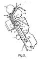
- the system comprises a pair of upper pinch rollers 1,2 ( Figure 2 ) into which banknotes are fed from an input hopper (not shown).
- the notes are guided by a pair of opposed guide plates 3,4 along a note path 5.
- the notes are guided past first and second infrared detector assemblies 6,7 located on opposite sides of the path to detect reflected infrared radiation.
- the notes then pass between a pair of middle pinch rollers 8,9 to a visible response detection system 10 where the notes are irradiated under visible light and the resultant reflected signal is obtained so as to determine the visible pattern of the facing surface of the note.
- the notes pass on between lower pinch rollers 11 (only one visible in Figure 2 ) to a diverter 12.
- Each IR detector assembly 6,7 includes an infrared emitter and an infrared detector for detecting infrared light reflected from the facing surface of the note.
- the detector assemblies 6,7 are mounted on the back of the guide plates 3,4 with the sensing elements sitting in slots in the plates such that the fronts of the sensors are 0.5mm sub-flush to the front of the plates. Keeping the detectors sub-flush minimises the risk of a note catching on a detector head.
- the guide plates 3,4 are finished in matt black or similar IR black finish to provide a reference or background surface for the opposite IR detector sensors.
- a control PCB 20 for the detectors is mounted on the side of the machine under the main covers (not shown).
- the IR detector assemblies are connected to the control PCB 20 ( Figure 1 ) that includes signal processing, storage for the expected responses and a microprocessor to perform the appropriate data analysing steps.
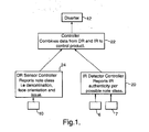
- Figure 1 shows the relationship between a Main Controller 22 of the counter, the IR detector controller 20 and a DR sensor (pattern detector) controller 24 connected to the visible response detection system 10.
- the DR sensor controller 24 examines each note as it arrives and by comparison to a set of templates determines the denomination, face and orientation of the note. This comparison can be carried out using any known pattern recognition technique. This is reported via an RS232 link to the Main Controller 22.
- the IR detector controller 20 also examines each note against a set of IR expected responses and reports to the Main controller 22 a confidence level of validity for each sensed note for each note type within the set of notes expected. This comparison could simply check that the received intensity of reflected i.r. lies in a predetermined range or that i.r. with an acceptable intensity is reflected from certain parts of the note. This table of data is then reported via the RS232 link to the Main Controller.
- the Main controller 22 then combines this data by using the information from the pattern detector controller 24 to select the appropriate data from the responses given by the IR detector.
- the DR sensor report may have indicated that the note had a denomination of 5, was face up and of issue 2.
- the IR detector report for this note could be that the IR response was valid.
- the note would be accepted, however, if the note was not recognisable or if the IR response for that particular note was reported as low confidence, the note would be rejected.
- Each infrared detector assembly 6,7 is composed of an external and an internal linear array each of 32 sensors, with the detector of each detector assembly reading a different face of the note.
- the product has two arrays reading the two different faces of the note, giving a two-sided IR test of the note.
- Each infrared array is composed of a single-lens auto-focused transmission/detection unit with a focal length of 4mm.
- this module we have an NIR transmitter and a receiver sensitive to 840nm, with resin insulation to block the direct infrareds as they are emitted.
- the emission from the transmitter is constant and the receiver is constantly active with a multiplexer system responsible for reading each pixel. This multiplexer system is integral to the internal array, while for the external set it is located on the external array control PCB.
- the detector arrays are composed of independent photodetection units with them all continuously emitting and reading the reflected signal. These units or array pixels have a 2.5mm focal length effecting a line reading every 2mm.
- the infrared detector is composed of an array of independent elements, but their optical response might at first vary. This can be compensated for, that is to say the array is grey-scale calibrated to retrieve the same response as before the reflection. This calibration is retained in the detection PCB and every time a reading is taken, the sensors are digitally corrected by the hardware.
- each one of the photo-diodes continues to detect presence, due to the increase in reflected light.
- the base black or reflection level there is a base black or reflection level and that this level rises when a note passes. This level is always lower than the maximum absorption obtained with the body of the note.
- the reflected level or IR from the IR black finish on the guide plate is lower than that reflected from the passing document. This ensures that the authentication data received is that of the document.
- the processing of currency is initiated by placing the notes into a tray (not shown).
- the notes are either sensed by an auto start sensor and the note feed process automatically starts, or the operator operates a switch to start the feed process.
- the notes are then counted by an opacity based doubles detect sensor (not shown) that checks both the short edge length and opacity of the note. From here the notes then pass over each of the IR sensors 6,7 and the DR sensor 10 where the note images are acquired for processing.
- a transport encoder (not shown) tracks the movement of the note and the results of the note processing must be available before it reaches the "decision point" within the transport.
- the decision point is that point in the process at which a decision must be made about activating a diverter mechanism within the document transport path to route the note away from the path.
- a diverter mechanism within the document transport path to route the note away from the path.
- the product is being used for a two-pocket operation (issue split, facing etc.) then when a problem note is identified then it is automatically routed to the top tray regardless of the other aspects of the note and the transport is stopped. After the transport has stopped, all the notes in the top tray need removing for reprocessing and the problem note needs to be separated for appropriate checks or repair.
Abstract
Description
- The invention relates to methods and apparatus for processing documents of value such as banknotes, cheques, postal orders and the like.
- The need for rapid counting of paper sheets, for example documents of value such as banknotes, has been long established and the introduction of the single pocket note counter provided major improvements in efficiency. These products were however somewhat limited as they could only count the number of pieces of paper that were conveyed through the machine regardless of their value or authenticity.
- Over the course of time further developments added size detection as a means of detecting rogue notes within a bundle of currency and indeed the further application of the size measurements allowed a determination of the value of the currency to be obtained. Providing of course that each denomination was of a discernibly different size. The processing by value of currency whose notes were all the same size, for example the US Dollar, was achieved by the step of using a pattern detector instead of a size detector.
- Similarly, the development of authentication devices allowed potential counterfeit notes to be identified during the note processing operation. Because of the need for these devices to be generic to all currencies only the simplest forms of authentication, such as UV fluorescence, were originally applied. Later currency specific devices for widely circulated currencies such as the US Dollar were developed. This latter authentication was almost invariably some form of magnetics detection. Detecting magnetic features is limiting, as the note needs to form intimate contact with the sensing head, which places arduous demands on the transporting of the banknotes. This can be particularly limiting when processing limp or damaged currency.
- The problem with the addition of this increased sophistication was that invariably the achievable note throughput would fall. This was because each time a problem note was identified the product would have to stop to allow the operator to examine and process the identified note. This was overcome by the introduction of counting devices that had more than one pocket and could therefore operate in a continuous manner (like a note sorter) whereby the problem note could be off sorted to either a second pocket or a reject area. The operator could now process the problem notes without the machine needing to stop thus greatly enhancing the efficiency of the product. Similar problems have been experienced in equipment for accepting cash deposits where there has become a requirement for more rapid accurate recognition and authentication of deposited documents as the time to process the acceptance or otherwise of inserted individual or bundles of documents is reduced.
- As stated earlier the types of authentication applied to such products have been chosen to be of a generic type applicable to most currencies or specifically targeted at the US Dollar. Detection techniques such as UV are now often regarded as of little benefit against the types of forgeries that are being created.
-
US-A-3916194 describes a note authentication system in which a note is exposed to infrared light and the response of the note monitored. - In accordance with one aspect of the present invention, a method of processing documents of value comprises:
- a) detecting a visible pattern on at least one side of a document;
- b) detecting the response of at least one side of the document to infrared radiation;
- c) comparing the detected visible pattern to one or more of a set of predetermined patterns corresponding to a set of documents types and identifying the document type if the detected visible pattern is sufficiently similar one of the predetermined patterns; and,
- d) comparing the response to infrared radiation to a set of IR expected responses to generate a confidence level of validity for each document type; and
- e) using the identified document type to select the appropriate data from the responses given by the IR detector and thereby determine whether the document is authentic.
- In accordance with another aspect of the present invention, apparatus for processing documents of value comprises a visible pattern detection system for detecting a visible pattern on at least one side of a document; an infrared response detection system including at least one infrared detector and infrared emitter for detecting the response of at least one side of a document to infrared radiation; and a processor adapted to compare the detected visible pattern to one or more of a set of predetermined patterns corresponding to a set of documents types so as to identify the document type if the detected visible pattern is sufficiently similar to the or one of the predetermined patterns, and to compare the response to infrared radiation to a set of IR expected responses to generate a confidence level of validity for each document type; and to use the identified document types to select the appropriate data from the responses given by the IR detector and thereby determine whether the document is authentic.
- The invention enables a new form of non-contact detection to be introduced into the banknote counting product environment that provides enhanced authentication processing that was previously only found in the much higher cost banknote sorting arena. The non-contact nature of the detector providing the advantage that note guiding constraints are minimised and the range of notes that can be processed is maximised.
- Commonly available equipment such as PC's with scanners and inkjet printers are now capable of creating visual images that are difficult to discern as being a counterfeit and matching the UV characteristics of a banknote is easily achieved. However, it is known that the inks used to create these images do not result in any form of image being visible when the note is illuminated and viewed in the IR spectrum. Real bank notes may be printed with inks that are known to produce a controlled response in the IR spectrum, albeit the response produced under IR light does not necessarily bear any relation to that in the visible domain. Indeed some banknotes are produced with inks, such as the De La Rue Delacode type, that are colour matched in the visible spectrum but that respond differently in the IR. A note can thus be printed with a continuous colour block in the visible and a varying intensity level in the IR.
- Processing such notes is best carried out in both the visible and IR spectra with the IR response being examined separately for each side of the note. The visible image is checked to ensure that it conforms to the visual aspects of the note and the IR spectra is checked for its authenticity. The IR response should be particularly checked in areas that are known to be printed with the colour matched types of ink.
- In one application, the method is used in a two pocket value balancing counter that is capable of providing a variety of functions inclusive of continuous note processing whilst simultaneously determining the value and authenticity of each note. A transmissive visible pattern detector determines the value of the note. The product is considerably enhanced by the addition of an IR detector that can operate in conjunction with the pattern detector.
- An example of a method and apparatus according to the present invention will now be described with reference to the accompanying drawing, in which:-
-
Figure 1 is a block diagram of the main components of a banknote denomination and authenticity detection system; and, -
Figure 2 illustrates part of a note transport. - The system comprises a pair of upper pinch rollers 1,2 (
Figure 2 ) into which banknotes are fed from an input hopper (not shown). The notes are guided by a pair ofopposed guide plates note path 5. - From the
upper pinch rollers 1,2, the notes are guided past first and second infrared detector assemblies 6,7 located on opposite sides of the path to detect reflected infrared radiation. The notes then pass between a pair ofmiddle pinch rollers response detection system 10 where the notes are irradiated under visible light and the resultant reflected signal is obtained so as to determine the visible pattern of the facing surface of the note. The notes pass on between lower pinch rollers 11 (only one visible inFigure 2 ) to adiverter 12. - Each
IR detector assembly - In order to avoid interference the detectors must not look directly at each other. The detector assemblies 6,7 are mounted on the back of the
guide plates - The
guide plates - A
control PCB 20 for the detectors is mounted on the side of the machine under the main covers (not shown). The IR detector assemblies are connected to the control PCB 20 (Figure 1 ) that includes signal processing, storage for the expected responses and a microprocessor to perform the appropriate data analysing steps. -
Figure 1 shows the relationship between aMain Controller 22 of the counter, theIR detector controller 20 and a DR sensor (pattern detector)controller 24 connected to the visibleresponse detection system 10. - The
DR sensor controller 24 examines each note as it arrives and by comparison to a set of templates determines the denomination, face and orientation of the note. This comparison can be carried out using any known pattern recognition technique. This is reported via an RS232 link to theMain Controller 22. TheIR detector controller 20 also examines each note against a set of IR expected responses and reports to the Main controller 22 a confidence level of validity for each sensed note for each note type within the set of notes expected. This comparison could simply check that the received intensity of reflected i.r. lies in a predetermined range or that i.r. with an acceptable intensity is reflected from certain parts of the note. This table of data is then reported via the RS232 link to the Main Controller. TheMain controller 22 then combines this data by using the information from thepattern detector controller 24 to select the appropriate data from the responses given by the IR detector. For example the DR sensor report may have indicated that the note had a denomination of 5, was face up and ofissue 2. The IR detector report for this note could be that the IR response was valid. On the basis of these two results the note would be accepted, however, if the note was not recognisable or if the IR response for that particular note was reported as low confidence, the note would be rejected. - The advantage of this form of processing is that the computationally intensive image processing in the detectors is carried out in parallel. This means the processing load within the machine is balanced and does not "bottleneck" on one or the other of the detectors. The aggregation of the results in the Main Controller however, still ensures that the verification of the inter-relationship of the IR signal and visible image is fully checked. Serial processing is also envisaged.
- Each
infrared detector assembly - Each infrared array is composed of a single-lens auto-focused transmission/detection unit with a focal length of 4mm. In this module we have an NIR transmitter and a receiver sensitive to 840nm, with resin insulation to block the direct infrareds as they are emitted. We also have a focal length of 4mm for each of these components, with signal variation from the collector being less than 20% against 0-4 mm variation in the reading distance. The emission from the transmitter is constant and the receiver is constantly active with a multiplexer system responsible for reading each pixel. This multiplexer system is integral to the internal array, while for the external set it is located on the external array control PCB.
- The detector arrays are composed of independent photodetection units with them all continuously emitting and reading the reflected signal. These units or array pixels have a 2.5mm focal length effecting a line reading every 2mm. By means of a multiplexer system we know at any moment the reflected level in each one of these pixels and with the bank of data so obtained we have a grey-scale reconstruction of the image obtained due to the fact that the position of said pixels never varies.
- The infrared detector is composed of an array of independent elements, but their optical response might at first vary. This can be compensated for, that is to say the array is grey-scale calibrated to retrieve the same response as before the reflection. This calibration is retained in the detection PCB and every time a reading is taken, the sensors are digitally corrected by the hardware.
- We continue to obtain the reflected values with digital compensation per photodiode with every 2mm the note advances as identified by the motor's encoder.
- As soon as the note reaches the array (whether external or internal glass) each one of the photo-diodes continues to detect presence, due to the increase in reflected light. Bear in mind that there is a base black or reflection level and that this level rises when a note passes. This level is always lower than the maximum absorption obtained with the body of the note.
- These analogue values obtained by reading line are converted into a value of grey, and with the group of readings obtained as the note passes through, we have a two-dimensional grey scale response.
- The reflected level or IR from the IR black finish on the guide plate is lower than that reflected from the passing document. This ensures that the authentication data received is that of the document.
- A study is then made by areas of the note with reference to the different contrasts obtained on both faces of the note, so obtaining the necessary information to determine the authenticity of the note.
- The processing of currency is initiated by placing the notes into a tray (not shown). Depending on the operating mode selected by the operator, the notes are either sensed by an auto start sensor and the note feed process automatically starts, or the operator operates a switch to start the feed process. The notes are then counted by an opacity based doubles detect sensor (not shown) that checks both the short edge length and opacity of the note. From here the notes then pass over each of the
IR sensors DR sensor 10 where the note images are acquired for processing. A transport encoder (not shown) tracks the movement of the note and the results of the note processing must be available before it reaches the "decision point" within the transport. The decision point is that point in the process at which a decision must be made about activating a diverter mechanism within the document transport path to route the note away from the path. In the example of a two-pocket sorter, to either the top 10 or bottom 12 stacker tray. - If the product is being used in a "single pocket mode" (value balancing, rogue outsort etc.) then all good notes are routed to a bottom tray and all suspect and rejected notes are routed to a top tray by the
diverter 12. Under these circumstances the product will provide continuous operation for the processing of the entire bundle of notes. Notes accumulating in the top tray can be processed by the operator whilst the remaining notes with the bundle are being counted. - If the product is being used for a two-pocket operation (issue split, facing etc.) then when a problem note is identified then it is automatically routed to the top tray regardless of the other aspects of the note and the transport is stopped. After the transport has stopped, all the notes in the top tray need removing for reprocessing and the problem note needs to be separated for appropriate checks or repair.
- Throughout all operations, error messages and count/ value information is shown in the LCD display.
Claims (11)
- A method of processing documents of value, the method comprising:a) detecting a visible pattern on at least one side of a document;b) detecting the response of at least one side of the document to infrared radiation;c) comparing the detected visible pattern to one or more of a set of predetermined patterns corresponding to a set of document types and identifying the document type if the detected visible pattern is sufficiently similar to one of the predetermined patterns;d) comparing the response to infrared radiation to a set of IR expected responses to generate a confidence level of validity for each document type; ande) using the identified document type to select the appropriate data from the responses given by the IR detector and thereby determine whether the document is authentic.
- A method according to claim 1, wherein steps a) and b) are carried out on the same side of the document.
- A method according to claim 1 or claim 2, wherein step d) comprises determining if the infrared radiation reflected from the document satisfies predetermined conditions.
- A method according to any of the preceding claims, wherein step b) comprises determining the response of one or more regions of the at least one side of the document to infrared radiation.
- A method according to any of the preceding claims, wherein if a document cannot be identified and/or authenticated, the document is either routed to one of a number of locations or is held stationary.
- A method according to any of the preceding claims, wherein the documents comprise banknotes.
- Apparatus for processing documents of value, the apparatus comprising a visible pattern detection system for detecting a visible pattern on at least one side of a document; an infrared response detection system including at least one infrared detector and infrared emitter for detecting the response of at least one side of a document to infrared radiation; and a processor adapted to compare the detected visible pattern to one or more of a set of predetermined patterns corresponding to a set of document types so as to identify the document type if the detected visible pattern is sufficiently similar to the or one of the predetermined patterns, and to compare the response to infrared radiation to a set of IR expected responses to generate a confidence level of validity for each document type; and to use the identified document type to select the appropriate data from the responses given by the IR detector and thereby determine whether the document is authentic.
- Apparatus according to claim 7, wherein the infrared response detection system comprises two sets of infrared emitters and detectors arranged on opposite sides of the transport path so as to monitor infrared radiation reflected by opposite sides of the documents.
- Apparatus according to claim 8, wherein the two sets of infrared emitters and detectors are offset from one another in the transport direction.
- Apparatus according to any of claims 7 to 9, wherein the or each infrared emitter is arranged opposite a an IR black reference surface.
- Apparatus according to any of claims 7 to 10, further comprising a transport system for transporting documents past the visible and infrared detection systems, the transport system including a diverter operable by the processor to divert documents to one of a number of output locations in accordance with the determined identity and/or authenticity.
Applications Claiming Priority (2)
| Application Number | Priority Date | Filing Date | Title |
|---|---|---|---|
| GBGB0003720.0A GB0003720D0 (en) | 2000-02-17 | 2000-02-17 | Document counter |
| GB0003720 | 2000-02-17 |
Related Child Applications (1)
| Application Number | Title | Priority Date | Filing Date |
|---|---|---|---|
| EP07115975 Division | 2007-09-07 |
Publications (2)
| Publication Number | Publication Date |
|---|---|
| EP1128338A1 EP1128338A1 (en) | 2001-08-29 |
| EP1128338B1 true EP1128338B1 (en) | 2008-10-01 |
Family
ID=9885838
Family Applications (1)
| Application Number | Title | Priority Date | Filing Date |
|---|---|---|---|
| EP01301382A Expired - Lifetime EP1128338B1 (en) | 2000-02-17 | 2001-02-16 | Document counter |
Country Status (7)
| Country | Link |
|---|---|
| US (1) | US6604636B2 (en) |
| EP (1) | EP1128338B1 (en) |
| AT (1) | ATE409929T1 (en) |
| DE (1) | DE60135940D1 (en) |
| ES (1) | ES2313930T3 (en) |
| GB (1) | GB0003720D0 (en) |
| PT (1) | PT1128338E (en) |
Families Citing this family (6)
| Publication number | Priority date | Publication date | Assignee | Title |
|---|---|---|---|---|
| FR2859806B1 (en) * | 2003-09-12 | 2005-12-23 | Sagem | APPARATUS FOR ANALYZING DOCUMENTS, IN PARTICULAR BANK NOTES |
| US8074806B2 (en) * | 2006-10-06 | 2011-12-13 | Glory Ltd. | Banknote handling apparatus |
| JP5193874B2 (en) * | 2006-10-24 | 2013-05-08 | グローリー株式会社 | Paper sheet counting device |
| CN102542333B (en) * | 2006-10-24 | 2015-07-22 | 光荣株式会社 | Paper counting device |
| JP6242570B2 (en) | 2012-09-06 | 2017-12-06 | 株式会社東芝 | Image reading apparatus and paper sheet processing apparatus |
| CN111429646B (en) * | 2020-05-07 | 2021-12-03 | 中国工商银行股份有限公司 | Banknote counter, banknote counting method, device, system and medium |
Family Cites Families (9)
| Publication number | Priority date | Publication date | Assignee | Title |
|---|---|---|---|---|
| US3916194A (en) * | 1974-01-07 | 1975-10-28 | Ardac Inc | Infrared note validator |
| EP0198819B1 (en) * | 1983-12-27 | 1988-08-24 | BERGSTRÖM, Arne | Apparatus for authenticating bank notes |
| CH690471A5 (en) * | 1988-04-18 | 2000-09-15 | Mars Inc | Means for detecting the authenticity of documents. |
| JPH02150983A (en) * | 1988-12-01 | 1990-06-11 | Fuji Electric Co Ltd | Paper money discriminating device |
| JPH0720790Y2 (en) * | 1990-07-19 | 1995-05-15 | 日本金銭機械株式会社 | Banknote removal prevention device |
| IT1250847B (en) * | 1991-10-15 | 1995-04-21 | Urmet Spa | BANKNOTE VALIDATION APPARATUS |
| JPH06203243A (en) * | 1992-12-25 | 1994-07-22 | Toyo Commun Equip Co Ltd | Genuineness/counterfeit discriminating device for sheet paper or the like |
| ES2077529B1 (en) * | 1993-12-27 | 1996-06-16 | Azkoyen Ind Sa | METHOD AND APPARATUS FOR THE CHARACTERIZATION AND DISCRIMINATION OF TICKETS AND LEGAL COURSE DOCUMENTS. |
| PE73298A1 (en) * | 1996-06-04 | 1998-11-13 | Coin Bill Validator Inc | BANK TICKET VALIDATOR |
-
2000
- 2000-02-17 GB GBGB0003720.0A patent/GB0003720D0/en not_active Ceased
-
2001
- 2001-02-14 US US09/781,958 patent/US6604636B2/en not_active Expired - Lifetime
- 2001-02-16 AT AT01301382T patent/ATE409929T1/en not_active IP Right Cessation
- 2001-02-16 ES ES01301382T patent/ES2313930T3/en not_active Expired - Lifetime
- 2001-02-16 PT PT01301382T patent/PT1128338E/en unknown
- 2001-02-16 DE DE60135940T patent/DE60135940D1/en not_active Expired - Lifetime
- 2001-02-16 EP EP01301382A patent/EP1128338B1/en not_active Expired - Lifetime
Also Published As
| Publication number | Publication date |
|---|---|
| US6604636B2 (en) | 2003-08-12 |
| GB0003720D0 (en) | 2000-04-05 |
| US20010048069A1 (en) | 2001-12-06 |
| PT1128338E (en) | 2008-12-17 |
| ES2313930T3 (en) | 2009-03-16 |
| ATE409929T1 (en) | 2008-10-15 |
| DE60135940D1 (en) | 2008-11-13 |
| EP1128338A1 (en) | 2001-08-29 |
Similar Documents
| Publication | Publication Date | Title |
|---|---|---|
| US5420406A (en) | Bill validator with bar code detector | |
| US6573983B1 (en) | Apparatus and method for processing bank notes and other documents in an automated banking machine | |
| US5966456A (en) | Method and apparatus for discriminating and counting documents | |
| EP1021788B1 (en) | Universal bank note denominator and validator | |
| US6560355B2 (en) | Currency evaluation and recording system | |
| US3916194A (en) | Infrared note validator | |
| US7215414B2 (en) | Module for validating deposited media items | |
| US20100000838A1 (en) | Banknote discrimination apparatus and banknote discrimination method | |
| US5483069A (en) | Validation apparatus for flat paper object | |
| EP1601599B1 (en) | Optical double feed detection | |
| KR101479850B1 (en) | An apparatus of identifying sheets | |
| EP1128338B1 (en) | Document counter | |
| JPWO2011086665A1 (en) | Paper sheet identification device and paper sheet identification method | |
| US20010040994A1 (en) | Counterfeit bills discriminating device with infrared ray transmitting array module and method of discriminating counterfeit bills | |
| US6094500A (en) | Apparatus for authenticating sheets | |
| KR200285318Y1 (en) | Counterfeit Detector Using Infra Radiation | |
| US9336638B2 (en) | Media item validation | |
| GB2444966A (en) | Validating sheet objects with a barcode and money value | |
| US20070108265A1 (en) | Currency note identification and validation | |
| EP3480794B1 (en) | Paper sheet identification system and paper sheet identification method | |
| US20040218800A1 (en) | Method and apparatus for identifying documents | |
| JP2791213B2 (en) | Banknote handling equipment | |
| WO2023176530A1 (en) | Paper sheet identifying device, paper sheet processing device, and paper sheet identification method | |
| CA2488017A1 (en) | Method and system for processing checks | |
| KR20160113878A (en) | Recognition apparatus for face value of bill and detection apparatus for counterfiet bill |
Legal Events
| Date | Code | Title | Description |
|---|---|---|---|
| PUAI | Public reference made under article 153(3) epc to a published international application that has entered the european phase |
Free format text: ORIGINAL CODE: 0009012 |
|
| AK | Designated contracting states |
Kind code of ref document: A1 Designated state(s): AT BE CH CY DE DK ES FI FR GB GR IE IT LI LU MC NL PT SE TR |
|
| AX | Request for extension of the european patent |
Free format text: AL;LT;LV;MK;RO;SI |
|
| 17P | Request for examination filed |
Effective date: 20020211 |
|
| AKX | Designation fees paid |
Free format text: AT BE CH CY DE DK ES FI FR GB GR IE IT LI LU MC NL PT SE TR |
|
| AXX | Extension fees paid |
Free format text: AL PAYMENT 20020211;LT PAYMENT 20020211;LV PAYMENT 20020211;MK PAYMENT 20020211;RO PAYMENT 20020211;SI PAYMENT 20020211 |
|
| RAP1 | Party data changed (applicant data changed or rights of an application transferred) |
Owner name: DE LA RUE INTERNATIONAL LIMITED |
|
| 17Q | First examination report despatched |
Effective date: 20061107 |
|
| GRAP | Despatch of communication of intention to grant a patent |
Free format text: ORIGINAL CODE: EPIDOSNIGR1 |
|
| GRAS | Grant fee paid |
Free format text: ORIGINAL CODE: EPIDOSNIGR3 |
|
| GRAA | (expected) grant |
Free format text: ORIGINAL CODE: 0009210 |
|
| AK | Designated contracting states |
Kind code of ref document: B1 Designated state(s): AT BE CH CY DE DK ES FI FR GB GR IE IT LI LU MC NL PT SE TR |
|
| AX | Request for extension of the european patent |
Extension state: AL LT LV MK RO SI |
|
| REG | Reference to a national code |
Ref country code: GB Ref legal event code: FG4D |
|
| REG | Reference to a national code |
Ref country code: CH Ref legal event code: EP |
|
| REG | Reference to a national code |
Ref country code: IE Ref legal event code: FG4D |
|
| REF | Corresponds to: |
Ref document number: 60135940 Country of ref document: DE Date of ref document: 20081113 Kind code of ref document: P |
|
| REG | Reference to a national code |
Ref country code: PT Ref legal event code: SC4A Free format text: AVAILABILITY OF NATIONAL TRANSLATION Effective date: 20081204 |
|
| REG | Reference to a national code |
Ref country code: SE Ref legal event code: TRGR |
|
| REG | Reference to a national code |
Ref country code: CH Ref legal event code: NV Representative=s name: ISLER & PEDRAZZINI AG |
|
| REG | Reference to a national code |
Ref country code: GR Ref legal event code: EP Ref document number: 20080403625 Country of ref document: GR |
|
| REG | Reference to a national code |
Ref country code: PT Ref legal event code: PC4A Owner name: TALARIS HOLDINGS LIMITED, GB Effective date: 20090210 |
|
| RAP2 | Party data changed (patent owner data changed or rights of a patent transferred) |
Owner name: TALARIS HOLDINGS LIMITED |
|
| REG | Reference to a national code |
Ref country code: ES Ref legal event code: FG2A Ref document number: 2313930 Country of ref document: ES Kind code of ref document: T3 |
|
| LTIE | Lt: invalidation of european patent or patent extension |
Effective date: 20081001 |
|
| NLS | Nl: assignments of ep-patents |
Owner name: TALARIS HOLDINGS LIMITED Effective date: 20090205 |
|
| REG | Reference to a national code |
Ref country code: GB Ref legal event code: 732E Free format text: REGISTERED BETWEEN 20090319 AND 20090325 |
|
| PG25 | Lapsed in a contracting state [announced via postgrant information from national office to epo] |
Ref country code: AT Free format text: LAPSE BECAUSE OF FAILURE TO SUBMIT A TRANSLATION OF THE DESCRIPTION OR TO PAY THE FEE WITHIN THE PRESCRIBED TIME-LIMIT Effective date: 20081001 |
|
| NLT2 | Nl: modifications (of names), taken from the european patent patent bulletin |
Owner name: TALARIS HOLDINGS LIMITED Effective date: 20090311 |
|
| PG25 | Lapsed in a contracting state [announced via postgrant information from national office to epo] |
Ref country code: FI Free format text: LAPSE BECAUSE OF FAILURE TO SUBMIT A TRANSLATION OF THE DESCRIPTION OR TO PAY THE FEE WITHIN THE PRESCRIBED TIME-LIMIT Effective date: 20081001 |
|
| PLBI | Opposition filed |
Free format text: ORIGINAL CODE: 0009260 |
|
| PG25 | Lapsed in a contracting state [announced via postgrant information from national office to epo] |
Ref country code: BE Free format text: LAPSE BECAUSE OF FAILURE TO SUBMIT A TRANSLATION OF THE DESCRIPTION OR TO PAY THE FEE WITHIN THE PRESCRIBED TIME-LIMIT Effective date: 20081001 Ref country code: DK Free format text: LAPSE BECAUSE OF FAILURE TO SUBMIT A TRANSLATION OF THE DESCRIPTION OR TO PAY THE FEE WITHIN THE PRESCRIBED TIME-LIMIT Effective date: 20081001 |
|
| PLAX | Notice of opposition and request to file observation + time limit sent |
Free format text: ORIGINAL CODE: EPIDOSNOBS2 |
|
| 26 | Opposition filed |
Opponent name: GLORY LTD. Effective date: 20090629 |
|
| PG25 | Lapsed in a contracting state [announced via postgrant information from national office to epo] |
Ref country code: MC Free format text: LAPSE BECAUSE OF NON-PAYMENT OF DUE FEES Effective date: 20090228 |
|
| NLR1 | Nl: opposition has been filed with the epo |
Opponent name: GLORY LTD. |
|
| REG | Reference to a national code |
Ref country code: IE Ref legal event code: MM4A |
|
| PLBB | Reply of patent proprietor to notice(s) of opposition received |
Free format text: ORIGINAL CODE: EPIDOSNOBS3 |
|
| PG25 | Lapsed in a contracting state [announced via postgrant information from national office to epo] |
Ref country code: IE Free format text: LAPSE BECAUSE OF NON-PAYMENT OF DUE FEES Effective date: 20090216 |
|
| PG25 | Lapsed in a contracting state [announced via postgrant information from national office to epo] |
Ref country code: LU Free format text: LAPSE BECAUSE OF NON-PAYMENT OF DUE FEES Effective date: 20090216 |
|
| PG25 | Lapsed in a contracting state [announced via postgrant information from national office to epo] |
Ref country code: CY Free format text: LAPSE BECAUSE OF FAILURE TO SUBMIT A TRANSLATION OF THE DESCRIPTION OR TO PAY THE FEE WITHIN THE PRESCRIBED TIME-LIMIT Effective date: 20081001 |
|
| PLBP | Opposition withdrawn |
Free format text: ORIGINAL CODE: 0009264 |
|
| PLBD | Termination of opposition procedure: decision despatched |
Free format text: ORIGINAL CODE: EPIDOSNOPC1 |
|
| PLBM | Termination of opposition procedure: date of legal effect published |
Free format text: ORIGINAL CODE: 0009276 |
|
| STAA | Information on the status of an ep patent application or granted ep patent |
Free format text: STATUS: OPPOSITION PROCEDURE CLOSED |
|
| 27C | Opposition proceedings terminated |
Effective date: 20130405 |
|
| REG | Reference to a national code |
Ref country code: FR Ref legal event code: PLFP Year of fee payment: 16 |
|
| PGFP | Annual fee paid to national office [announced via postgrant information from national office to epo] |
Ref country code: ES Payment date: 20160223 Year of fee payment: 16 Ref country code: TR Payment date: 20160208 Year of fee payment: 16 Ref country code: CH Payment date: 20160223 Year of fee payment: 16 Ref country code: IT Payment date: 20160222 Year of fee payment: 16 |
|
| PGFP | Annual fee paid to national office [announced via postgrant information from national office to epo] |
Ref country code: SE Payment date: 20160217 Year of fee payment: 16 Ref country code: PT Payment date: 20160212 Year of fee payment: 16 Ref country code: GR Payment date: 20160219 Year of fee payment: 16 Ref country code: FR Payment date: 20160222 Year of fee payment: 16 |
|
| REG | Reference to a national code |
Ref country code: CH Ref legal event code: PL |
|
| REG | Reference to a national code |
Ref country code: SE Ref legal event code: EUG |
|
| PG25 | Lapsed in a contracting state [announced via postgrant information from national office to epo] |
Ref country code: LI Free format text: LAPSE BECAUSE OF NON-PAYMENT OF DUE FEES Effective date: 20170228 Ref country code: GR Free format text: LAPSE BECAUSE OF NON-PAYMENT OF DUE FEES Effective date: 20170906 Ref country code: CH Free format text: LAPSE BECAUSE OF NON-PAYMENT OF DUE FEES Effective date: 20170228 |
|
| PG25 | Lapsed in a contracting state [announced via postgrant information from national office to epo] |
Ref country code: PT Free format text: LAPSE BECAUSE OF NON-PAYMENT OF DUE FEES Effective date: 20170816 Ref country code: SE Free format text: LAPSE BECAUSE OF NON-PAYMENT OF DUE FEES Effective date: 20170217 |
|
| REG | Reference to a national code |
Ref country code: FR Ref legal event code: ST Effective date: 20171031 |
|
| PG25 | Lapsed in a contracting state [announced via postgrant information from national office to epo] |
Ref country code: FR Free format text: LAPSE BECAUSE OF NON-PAYMENT OF DUE FEES Effective date: 20170228 |
|
| PG25 | Lapsed in a contracting state [announced via postgrant information from national office to epo] |
Ref country code: IT Free format text: LAPSE BECAUSE OF NON-PAYMENT OF DUE FEES Effective date: 20170216 |
|
| REG | Reference to a national code |
Ref country code: ES Ref legal event code: FD2A Effective date: 20180629 |
|
| PG25 | Lapsed in a contracting state [announced via postgrant information from national office to epo] |
Ref country code: ES Free format text: LAPSE BECAUSE OF NON-PAYMENT OF DUE FEES Effective date: 20170217 |
|
| REG | Reference to a national code |
Ref country code: DE Ref legal event code: R082 Ref document number: 60135940 Country of ref document: DE Representative=s name: KEIL & SCHAAFHAUSEN PATENTANWAELTE PARTGMBB, DE Ref country code: DE Ref legal event code: R082 Ref document number: 60135940 Country of ref document: DE Representative=s name: KEIL & SCHAAFHAUSEN PATENT- UND RECHTSANWAELTE, DE |
|
| PGFP | Annual fee paid to national office [announced via postgrant information from national office to epo] |
Ref country code: NL Payment date: 20200227 Year of fee payment: 20 Ref country code: GB Payment date: 20200226 Year of fee payment: 20 |
|
| REG | Reference to a national code |
Ref country code: DE Ref legal event code: R119 Ref document number: 60135940 Country of ref document: DE |
|
| PG25 | Lapsed in a contracting state [announced via postgrant information from national office to epo] |
Ref country code: DE Free format text: LAPSE BECAUSE OF NON-PAYMENT OF DUE FEES Effective date: 20200901 |
|
| REG | Reference to a national code |
Ref country code: NL Ref legal event code: MK Effective date: 20210215 |
|
| REG | Reference to a national code |
Ref country code: GB Ref legal event code: PE20 Expiry date: 20210215 |
|
| PG25 | Lapsed in a contracting state [announced via postgrant information from national office to epo] |
Ref country code: GB Free format text: LAPSE BECAUSE OF EXPIRATION OF PROTECTION Effective date: 20210215 |
|
| PG25 | Lapsed in a contracting state [announced via postgrant information from national office to epo] |
Ref country code: TR Free format text: LAPSE BECAUSE OF NON-PAYMENT OF DUE FEES Effective date: 20170216 |