EP1128267A1 - Festplatterspeicherungssystem mit redundanten Festkörperspeicherungsgeräten - Google Patents
Festplatterspeicherungssystem mit redundanten Festkörperspeicherungsgeräten Download PDFInfo
- Publication number
- EP1128267A1 EP1128267A1 EP00301486A EP00301486A EP1128267A1 EP 1128267 A1 EP1128267 A1 EP 1128267A1 EP 00301486 A EP00301486 A EP 00301486A EP 00301486 A EP00301486 A EP 00301486A EP 1128267 A1 EP1128267 A1 EP 1128267A1
- Authority
- EP
- European Patent Office
- Prior art keywords
- data
- data storage
- solid state
- area
- storage device
- Prior art date
- Legal status (The legal status is an assumption and is not a legal conclusion. Google has not performed a legal analysis and makes no representation as to the accuracy of the status listed.)
- Withdrawn
Links
Images


Classifications
-
- G—PHYSICS
- G06—COMPUTING; CALCULATING OR COUNTING
- G06F—ELECTRIC DIGITAL DATA PROCESSING
- G06F11/00—Error detection; Error correction; Monitoring
- G06F11/07—Responding to the occurrence of a fault, e.g. fault tolerance
- G06F11/16—Error detection or correction of the data by redundancy in hardware
- G06F11/20—Error detection or correction of the data by redundancy in hardware using active fault-masking, e.g. by switching out faulty elements or by switching in spare elements
- G06F11/2053—Error detection or correction of the data by redundancy in hardware using active fault-masking, e.g. by switching out faulty elements or by switching in spare elements where persistent mass storage functionality or persistent mass storage control functionality is redundant
- G06F11/2056—Error detection or correction of the data by redundancy in hardware using active fault-masking, e.g. by switching out faulty elements or by switching in spare elements where persistent mass storage functionality or persistent mass storage control functionality is redundant by mirroring
- G06F11/2087—Error detection or correction of the data by redundancy in hardware using active fault-masking, e.g. by switching out faulty elements or by switching in spare elements where persistent mass storage functionality or persistent mass storage control functionality is redundant by mirroring with a common controller
-
- G—PHYSICS
- G06—COMPUTING; CALCULATING OR COUNTING
- G06F—ELECTRIC DIGITAL DATA PROCESSING
- G06F11/00—Error detection; Error correction; Monitoring
- G06F11/07—Responding to the occurrence of a fault, e.g. fault tolerance
- G06F11/14—Error detection or correction of the data by redundancy in operation
- G06F11/1402—Saving, restoring, recovering or retrying
- G06F11/1446—Point-in-time backing up or restoration of persistent data
- G06F11/1456—Hardware arrangements for backup
Definitions
- the present invention relates to data storage devices for storage of electronic data, and particularly though not exclusively to a data storage device comprising at least one rotating disk drive, and one or more solid state data storage devices capable of substantially faster read and write operations than the disk drive.
- Conventional data storage systems for high capacity data storage include conventional 'hard drive' disk drive devices as are well-known in the art.
- Conventional disk drive comprise a rotating disk having a magnetically readable and writeable coating, which revolves at high revolutions per minute.
- Such disk drives may store data capacities in the range 4 to 32 Gbytes or more for each individual drive.
- devices are arranged in arrays, for example in redundant arrays of inexpensive disks (RAID arrays) as are known in the art.
- Conventional hard disk drives have relatively slow access times for accessing data, compared to conventional solid state devices such as dynamic random access memories (DRAM). The relatively high access time for accessing data in a hard disk drive is predominantly a result of moving a read head to read a particular part of the rotating disk.
- DRAM dynamic random access memories
- Hard disk drives are extremely common due to their relatively low price per unit data storage capacity.
- solid state data storage devices having relatively lower densities of data storage, and having much faster access times than hard disk drives but with higher costs than hard disk drives.
- Such devices are currently niche market devices, due to their cost.
- These solid state memory devices have data storage capacities between those of hard disk drives and conventional DRAM's.
- the applicants have developed a data storage system having a combination of rotating hard disk drive and solid state data storage devices in a form which is capable of low cost production and which may be suitable for large scale mass market applications. Such systems may provide a high performance data storage device solution for replacement of conventional hard disk drives in mass market applications.
- the applicants have studied how users may wish to actually utilize the high performance solid state data storage devices in customer applications, and as a result of this study have identified various problems with the usage of these high performance data storage devices.
- the applicants estimate that the optimum usage of such high performance data storage devices would be in conjunction with one or more conventional hard disk drives.
- the applicants envisage that a plurality of high performance solid state non volatile data storage devices will be used in conjunction with one or a plurality of conventional hard disk drive devices, whereby more frequently accessed data is stored on the solid state data storage device, whereas less frequently accessed data is stored on a hard disk drive.
- a least cost solution is to provide a single high performance solid state data storage device in series with one or more rotating disk drives, where data is read and written through the solid state device, such that most frequently used data is cached within the solid state data storage device.
- RAID devices use a plurality of redundantly arranged disks such that data is encoded over a number of disks, so that an individual disk can fail, whilst the data is still recoverable from redundancy encoded data stored on the other disks.
- Introducing a single high performance solid state data storage device introduces a single point of failure into a data storage system. Any data which is solely stored on the solid state data storage device will be at risk of loss if the device should fail.
- a possible alternative solution to the problem of single point of failure using an arrangement of a high performance solid state data storage device and one or a plurality of hard disk drives is to use two high performance solid state data storage devices, which mirror each other in the data which each device stores. The presence of duplicate copies of data removes the single point of failure.
- a disadvantage of this solution is that the cost of this system increases substantially due to the use of two high performance solid state data storage devices, but only the benefit of the storage capability of a single high performance solid state data storage device is achieved, the second high performance data storage device being wholly redundant.
- the present invention relies on the use of two high performance solid state data storage devices and at least one rotating disc data storage device operating under control of a controller device, and makes efficient utility of the available user data storage space in both high performance solid state data storage devices.
- the result is the provision of a bulk data storage system having a fast write time, but with removal of any single point of failure in a data storage system, with the benefit of an enhanced effective reliability. More than half the data storage space on the combined plurality of high performance data storage devices may be available for use for storing user data.
- One effect of the specific embodiments of the present invention may be to speed up access to user data stored in a data storage device system or subsystem comprising a plurality of disk drives.
- an objective is to provide rapid write times and rapid read times, so that data which would otherwise be stored on a rotating hard disk, thereby incurring long access times, is instead stored in a fast access memory, reducing the access time for regularly accessed information.
- an objective is to provide a rapid write access to large volumes of memory, so that a write confirmation signal can be rapidly returned to a host device, so that a processing in the host device is not delayed in processing data, by waiting for a write acknowledgement signal, thereby allowing the processor to carry out other data processing tasks sooner.
- a fast write process to large amounts of memory may be available to a host, using the presently disclosed data storage system.
- Two or more high performance non volatile solid state data storage devices are arranged with at least one disk drive partition in a group.
- Each high performance data storage device is logically divided into two partitions, the larger partition of each high performance data storage device being allocated to user data, and a smaller partition of each of high performance data storage device being allocated as a data staging area.
- the first data staging area in the first high performance data storage device is logically matched to the second user data area of the second high performance data storage device and vice versa
- the second data staging area of the second high performance data storage device is logically matched to the first user data area of the first high performance data storage device.
- the disk drive partitions which are part of the group, are used to capture data from the data staging areas. Movement of data between the high performance solid state devices and the hard disk drive(s) is achieved under control of a controller device.
- non volatile solid state data storage device is used to mean a data storage device having no moving parts, and which retains memory of data for an extended period of days or months when external power is removed from the device.
- Such devices may include magnetic random access memory (MRAM) devices, dynamic random access memory (DRAM) devices having a battery power supply, ferro-electric random access memory (FERAM) devices, and flash electrically programmable read only memory devices.
- MRAM magnetic random access memory
- DRAM dynamic random access memory
- FERAM ferro-electric random access memory
- flash electrically programmable read only memory devices Such devices may be implemented as discrete units, for example of a size and shape suitable for direct replacement of conventional rotating disk hard drives, or may be implemented as part of a controller device of a RAID, on a same chip or component board as such a controller device.
- a write operation to the group routes the user data to be stored to the user data area of the first high performance data storage device. Additionally, a copy of the data is written to the second data staging area of the second high performance data storage device. Once this is complete, a host computer considers the transaction complete and is free to carry on with other functions. This results in a substantially shorter write time than a write time to a conventional hard disk drive.
- data stored in the second data staging area of the second high performance data storage device is copied to the disk drive partition of a conventional disk drive data storage device and deleted from the second data staging area of the high performance data storage device. This frees up staging space for subsequent write operations to the second data staging area of the second high performance data storage device and may allow the second size of the second data staging area to be substantially smaller than the user data space on the second high performance data storage device.
- Read operations from the group are directed to a said user data area on the first or second high performance data storage device.
- a data storage system comprising:
- a said solid state data storage device comprises a controller device comprising a processor and a computer program for controlling said processor, said controller device operating to:
- a said solid state data storage device may comprise a magnetic random access memory device.
- Said solid state data storage device may comprise at least one intrinsically volatile dynamic random access memory, and at least one battery device, providing a combined non-volatile solid state data storage device.
- Said solid state data storage device may comprise a non-volatile flash electrically programmable read only memory.
- Said solid state data storage device may comprise a ferroelectric random access memory device.
- said solid state data storage devices have a memory capacity of greater than 1 Gbyte.
- said solid state data storage devices are non-volatile devices.
- a said data staging area comprises less than 50% of the data storage capacity of a corresponding said solid state data storage device.
- the data storage system comprises a controller device comprising a processor and a computer program for controlling said processor, and a plurality of data buses connecting said controller with said plurality of solid state data storage devices, wherein each said solid state data storage device communicates with said controller device by a corresponding respective separate said bus.
- a method of storing data in a data storage system comprising a plurality of rotating disk drive data storage devices and a plurality of solid state data storage devices, said method comprising the steps of:
- the method may further comprise the steps of:
- Said step of writing data to said second data staging area and said first user data area may comprise:
- Preferably said method comprises the steps of: if new data has been written to said second data staging area, copying data of said second data staging area to said first data partition area of said plurality of rotating disks.
- said method comprises the steps of:
- Said step of writing data to said first data staging area and said second user data area may comprise:
- Preferably said method comprises the steps of: if new data has been written to said first data staging area, moving said data of said first data staging area to a second data partition area of said plurality of disks.
- Preferably said method comprises the steps of: if new data has been written to said first data staging area, moving data of said first data staging area to said second data partition area of said plurality of rotating disks.
- said method comprises the steps of:
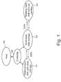
- a controller means 103 receives data from a host computer 100 and can read and write to a first memory area 101 of relatively slow access time memory, provided by one or a plurality of rotating hard disk drives.
- the controller means 103 can also read and write data from one or a plurality of faster access memory areas provided by non-volatile solid state data storage devices 102, having a relatively faster access time than the hard disk data storage devices.
- Data is transferred between the hard disk data storage area 101 and the solid state data storage area 102 under control of the controller means 103, which is typically implemented as a computer program and processor.
- a hard disk partition memory area 104 is used to regularly back up data from the solid state data storage device memory area to provide recovery of data in the event of a failure of either solid state data storage device.
- Selected data is moved from the rotating disk data storage devices onto the solid state data storage devices.
- the data selected is suitably the most frequently accessed data.
- Data which is accessed less frequently may be stored on the rotating hard disk data storage devices, where access times are slower. Therefore, for the most frequently accessed data read/write times are improved compared to the conventional case using rotating disk data storage devices.
- conventional rotating hard disk drives are retained in the data storage system for storage of bulk user data which is relatively less frequently accessed. For a host computer using the data storage system, there is an overall improvement in data storage access times for much of the data which is read and written to the data storage system, compared to a prior art data storage system having solely rotating hard disk drives.
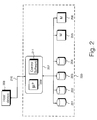
- a physical architecture of a data storage system 200 comprising an array of one or a plurality of rotating disk data storage devices 201-204; two or more non-volatile solid state high capacity memory data storage devices 205, 206; and a controller device 207 for managing storage of data amongst the one or plurality of rotating disk data storage devices and the plurality of solid state data storage devices.
- a host device 208 reads and writes data from and to the data storage system 200, via a known small computer system interface (SCSI) cable, or a known Fiber Channel Association cable and interface 210.
- SCSI small computer system interface
- the data storage system of Fig. 2 may comprise a legacy redundant array of inexpensive disks (RAID) device, with the addition of the plurality of non-volatile solid state data storage devices 205, 206 and associated controller 207 for controlling transfer of data between the rotating disk drives and the solid state memory devices.
- RAID redundant array of inexpensive disks
- Each solid state data storage device may externally look very similar to a rotating hard disk data storage device, being of a similar size, shape and weight. However, the solid state data storage device may have read and write times of the order of 1000 times quicker than the conventional rotating disk hard drive unit.
- the solid state data storage devices may typically have a data storage capacity of one to two Gbytes.
- the solid state data storage devices comprise Magnetic Random Access Memory (MRAM) data storage devices. These devices are non-volatile, and have relatively fast read and write access times compared to conventional rotating disk hard drive units.
- MRAM devices are intrinsically non-volatile, that is to say when electrical power supply is removed from the devices, the data is retained in the memory and is not lost.
- the solid state of data storage devices may comprise flash EPROMS, ferro electric random access memories (FERAM), or Dynamic Random Access Memory (DRAM) arrays.
- DRAM Dynamic Random Access Memory
- DRAM devices are intrinsically volatile, and lose their stored data when power is removed.
- FERAM ferro electric random access memories
- DRAM's provide better performance in terms of read and write access times than a comparable MRAM unit, there is the disadvantage of the need to provide a battery back-up to overcome the intrinsic volatility of DRAM devices to provide a non-volatile DRAM data storage unit.
- flash EPROM's are intrinsically non-volatile, but have poorer read and write access times than a comparable MRAM device.
- FERAM devices are intrinsically non volatile, and have access times comparable with those of MRAM devices, but have much lower storage capacity densities.
- MRAM data storage units, DRAM data storage units and EPROM data storage units are alternative embodiments, but in the best mode the MRAM data storage unit is selected to give the optimum combination of intrinsic non-volatility, and fast read and write access times.
- Controller device 207 comprises a local processor 209 having the task of managing data transfers between the first and second solid state data storage devices and the one or more hard disk drives, and managing storage of data as between the plurality of hard disk drives.
- the local processor operates in accordance with control software 211, operating a plurality of management algorithms for effecting the data transfers between individual data storage devices in the data storage system 200.
- user data may be striped across the plurality of rotating hard disk drives, such that blocks of user data are redundancy encoded using a known error correction coding, for example a Reed Solomon coding, and each data block is stored across the plurality of rotating disk drives.
- a known error correction coding for example a Reed Solomon coding
- the data stored on that disk drive may be recoverable from the redundancy coding in the data stored on the other rotating disk drives. If any one disk fails, there is enough data on the remaining disks to reconstruct the lost data on the failed disk.
- a new replacement disk drive can be inserted to replace the failed disk drive and the lost data on the new disk drive can be reconstituted automatically from the redundancy coded data on the other disk drives.
- the provision of two or more solid state data storage devices overcomes the risk of a single point of failure, in the event that one of the solid state data storage devices should fail. Thus, a single point of failure in terms of hardware is avoided.
- the plurality of hard disk drives are augmented by the plurality of solid state data storage devices in a way such that the introduction of the solid state data storage devices do not introduce a single point of failure into the data storage system 200.
- a simple mirror replication of the data stored on first solid state data storage device 205 onto second solid state data storage device 206 would achieve reliability. However, this is an inefficient solution, since there is incurred the cost of two solid state data storage devices, but the memory capacity of only one solid state data storage device is utilized.
- the data storage system operates such that as files are retrieved from the one or more rotating disk data storage devices, they are copied to the solid state data storage devices 205, 206 which act as a cache for those files.
- Various logical rules may be embedded in the controller device 207 for determining when a file will be copied to the solid state data storage devices, to achieve optimum performance.
- the controller device may include one or a plurality of algorithms for determining which data files are the most used, and for determining whether these should be stored in the solid state memory data storage device, or overwritten in the solid state data storage device.
- the solid state data storage devices act as a cache for the one or more rotating disk drives.
- the controller device 207 maintains a table data containing entries of where each block of data has been stored. As data is moved from the solid state data storage device memory to the rotating disk drive area, and back again from the rotating disk drive areas to the solid state data storage device areas, the table data is updated. In the event of a failure of either solid state data storage device, the controller can determine where a block of lost data is also copied either on the other solid state data storage device or on the plurality of rotating disk drives.
- the solid state data storage devices are configured as permanent user data storage areas to augment the storage areas of the one or more rotating hard disk drives, for permanent storage of bulk user data.
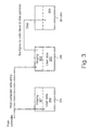
- FIG. 3 there is illustrated schematically partitioning of data areas within the first and second solid state data storage devices 205, 206 and movement of data between memory areas on the solid state data storage devices and the hard disk drive data storage devices.
- full redundancy may be achieved, whilst utilizing more than the data storage capacity of one solid state data storage device and achieving as far as possible the combined data storage capacity of both solid state data storage devices.
- the first solid state data storage device 205 is partitioned logically such that there is a first main user data area 300, which forms the bulk of the memory capacity of the device, and a first data staging area 301.
- the second solid state data storage device is partitioned into a second user data area 302, occupying the bulk of the memory area of that solid state data storage device, and a second data staging area 303.
- each data staging area may constitute less than 50% of the total memory capacity of the corresponding respective solid state data storage device.
- control device 207 Whilst the best mode implementation herein shows a separate processor 209 comprising control device 207, in principle, the functions of the control device can be provided by software in the host device 208 itself. However, this has the disadvantage of taking up processing power from a processor in the host device 208.
- the best mode implementation described herein is aimed at a mid-range data storage solution. The invention is not limited to use of a separate processor at the control device 207, and the functionality of the control device 207 may be carried out using a processor in host device 208.
- Fig. 3 illustrates a first storage operation of a host computer writing to the data storage system.
- the host computer may see the controller 207 of the data storage system as one logical drive unit, for example drive D.
- the controller handles data storage to all the data storage devices in the data storage system.
- the host computer when it writes data to the data storage system writes data to the controller 207, which then writes data to the first user data area 300 of the first solid state data storage device, and writes a copy of that same data into the second data staging area 303 of the second solid state data storage device. These write operations occur simultaneously.
- the second data staging area 303 has a significantly lower data capacity than the first user data area 300, if data is continued to be written to the data storage system, the second data staging area 303 will be the first high performance data storage area to become full. Therefore, the controller device 207 moves the data in the second data staging area 303 into a first partitioned memory area 304 stored on the plurality of hard disk drives.
- the memory management strategy is to keep the second data staging area 303 as empty as possible, by regularly transferring the data stored in that staging area onto the first partition area 304 in the plurality of disk drives 201-204, as soon as possible after data is received in the second data staging area.
- the second data staging area 303 is emptied on a first in-first out basis to the first hard disk data partition.
- other algorithms for selecting the data to be emptied are possible. It is important to ensure that the second data staging area 303 does not overflow, resulting in overwrite of data, before this data has been backed up onto the first data partition area 304 on the hard disk drives. If the second data staging area 303 is allowed to become full, then any write operations from the host computer will be held off, and the host computer could stall.
- a first write process carried out by controller device 207 upon receiving a data block from host device 208, for storage in the data storage system.
- data written into the first solid state data storage device 205 must be replicated in the second solid state data storage device 206, in case either of the solid state data storage devices should fail.
- step 400 a block of data is received from the host device 208 by the controller device 207.
- step 401 the block of data is written to the first user data area of the first solid state memory device.
- the same data block is written to the second data staging area of the second solid state memory device.
- steps 401, 402 may be carried out in interleaved manner, such that part of the data block is written to the first solid state storage device 205, followed by the same segment of data being written to the second solid state storage device 206, followed by a further segment written to the first said state data storage device, the further segment being written to the second solid state data storage device and so on until the whole of the data block has been written to both solid state data storage devices segment by segment.
- this operation therefore takes twice as long (i.e. about 20 ⁇ s) as writing the data block to a single solid state data storage device.
- the write times to the solid state data storage device are of the order of 10 ⁇ s, this is of the order of one thousand times faster than the write time to the conventional rotating disk drive, which is of the order of 10 ms. Therefore, doubling the write time to the solid state data storage device is insignificant compared to the write time to a rotating disk drive device.
- the write speed can be reduced to the write time of a single solid state data storage device, if two processors are used in parallel to write the segments of data to the first and second solid state storage devices simultaneously in parallel.
- a single processor is used for reasons of cost reduction, and the small disadvantage in increased write time to the solid state data storage devices is accepted.
- step 404 once the control device 207 has written the complete data block to both solid state data storage devices, it sends a confirmation signal back to the host device 208, which the host device may use as a trigger to send a further data block for storage.
- prior art conventional volatile cache plus hard disk data storage devices operate on a write-through basis, in which data written to the cache is re-written on to the rotating hard disk drive before an acknowledgement signal is sent back to a host computer writing the data.
- it is ensured that the data is written to non-volatile memory on the rotating disk, before an acknowledgement signal is sent back to the host device.
- no acknowledgement signal will be received, and the data stored in volatile memory may be lost.
- the host device will then re-send the data, because the acknowledgement signal has not been received.
- the conventional write-through cache data storage systems incur the penalty of slow access time to the rotating hard disk drives.
- an acknowledgement signal is received by a host device faster, because data is written to a quick access time high performance high capacity non-volatile solid state data storage device.
- This write time of approximately 20 ⁇ s in the best mode herein compares with a prior art write time, taking example of a prior art 5-disk raid array, of the order of 40 ms.
- the prior art raid array has a relatively high write time because the data is striped across the 5-disks, and in order to check that the data has been written correctly, the data must also be re-read from each of the 5 disks by a control device. Therefore a significant write speed advantage is achieved by the best mode implementation over prior art arrays.
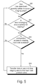
- FIG. 5 there is illustrated schematically a first back-up process of the data storage system.
- data in the second data staging area 303 of the second solid state data storage device is transferred to the first partition area 304 on the plurality of disks 201-204, as soon as the solid state data storage device is available to read from.
- the data in the second data staging area 303 is re-written to the first data partition area as soon as possible, in order to keep the second staging area 503 available for receiving as large a quantity of write data as possible.
- This is in contrast to a conventional prior art volatile cache, where the cache is emptied as late as possible, in order to cache as large a quantity as data at once as possible.
- Second staging area 303 is used to transiently store data on its way to the first rotating disk partition area 304. The same data is also stored in the first user data area 300, so that if the second solid state data storage device fails at any time, data recovery is available from the first solid state data storage device.
- step 500 the processor 209 under control of control software 211 checks whether any data has been recently written to the second data staging area 303. If new data has been recently written to the second staging area, then in step 501 the controller checks whether the second staging area is available for reading, that is to say checks that the second solid state memory device is not busy, and checks in step 502 whether there is unimpeded access to the rotating hard disk(s). If both the hard disk drives and the second staging area are available, then in step 503 data is transferred from the second data staging area to the first hard disk partition area.
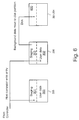
- FIG. 6 there is illustrated schematically a second storage operation of the data storage system carried out contemporaneously with the processes described with reference to Figs. 3-5 herein, for writing a second block of data to the data storage system.
- An equivalent process to that described with reference to Figs. 3 to 5 occurs during a write operation of a block of data from the host device, whereby the second block of data is written to the second user data area 302 of the second solid state data storage device, and to the first data staging area 301 of the first solid state data storage device.
- the data written into the first data staging area is periodically backed up to a second partition memory area 600 on the plurality of disk drives 201-204.
- the first data staging area 301 has written to it the same data as the second user data area 302
- the second data staging area 303 has the same data written to it as the first user data area 300
- the second data staging area 303 is backed up onto the first hard disk partition area 304
- the first data staging area 304 is backed up onto the second hard disk partition area 600.
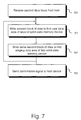
- step 700 the second data block is received by the controller device from the host device.
- step 701 the received block of data is written to the second user data area of the second solid state memory device.
- step 701 the same block of data is written to the first data staging area 301 of the first solid state memory device in step 702.
- steps 401 and 402 described herein above writing of a block of data to the second user data area and the first data staging area is made by partitioning the second block of data into segments of data which are written alternatively to the second user data area and first data staging area until the whole of the data block has been written.
- step 703 the block of data having been written to the second user data area and the first data staging area, a confirmation signal is returned to the host device, upon receipt of which the host device may send a further block of data.
- Fig. 8 there is illustrated schematically a background back up operation for backing up the content of the first data staging area to the second hard disk partition area.
- the process of Fig. 8 is similar and runs in parallel to the process described herein before with reference to Fig. 5.
- the processor 207 determines whether new data has been written to the first staging area.
- step 801 it is checked whether the first staging area is available for reading.
- step 802 it is checked whether the rotating hard disk drive(s) have unimpeded write access.
- step 803 provided the second solid state data storage device is available for reading, and the one or more rotating disk drives are available for writing, then data is transferred from the first data staging area in the second solid state data storage device on to the second hard disk partition area, thereby emptying the data in the first data staging area on to the rotating hard disk drives.
- staging areas are is needed because writing to a single solid state data storage device would give a single point of failure without there being parallel writing to another solid state memory storage device. It is important that at every stage, there are always two copies of the data. In the best mode, the two copies of each segment of a first block of data exist either:
- a second block of data is stored in the first and second solid state data storage devices, and this has at least two copies stored at all times including:
- the first block of data is mirrored, and additionally the second block of data is mirrored.
- the rate at which the data staging area can be emptied is limited by the rate at which the data can be transferred and written to the hard disk.
- the access time to a host computer is therefore twice the access time of each of the solid state devices, of approximately 10-20 ⁇ s, being a significant improvement on the millisecond access times of prior art hard disk storage arrays.
- Single point of failure is eliminated by the use of a pair of solid state data storage devices.
- data can be written in parallel to the two solid state devices, and the access time is equivalent to the access time of one solid state device.
- the size of the first and second data staging areas 304, 600 are preferably large enough to contain all the data in the first and second user data areas 300, 302. With current solid state data storage technology each non-volatile solid state device will typically have a data capacity of the order of 2Gbytes.
- the solid state data storage devices have no moving parts, their reliability can be expected to be greater than the reliability of a conventional rotating hard disk drive having moving parts. However, even though the probability of failure of a solid state device is lower than that of a rotating hard disk drive, redundancy by provision of two solid state data storage devices is still desirable to avoid a single point of failure.
- Data stored on the plurality of solid state data storage devices and in the partition area of the rotating disk drive memories need not be redundancy encoded, since physical redundancy exists by virtue of the copies of data being present on either two solid state data storage devices and/or a solid state data storage device and a hard disk partition area.
- access times are significantly improved to the data storage device.
- Calculation of error correction codes incurs a time penalty which is significant compared to the write time to the solid state data storage devices. This is not the case for writing to rotating disk drive devices, where the error correction code times are small compared to the write times to the rotating disk drives.
- the control device 207 becomes aware of any failures of a said solid state data storage device by means of a conventional command-acknowledgement protocol as is known in the art.
Priority Applications (3)
| Application Number | Priority Date | Filing Date | Title |
|---|---|---|---|
| EP00301486A EP1128267A1 (de) | 2000-02-25 | 2000-02-25 | Festplatterspeicherungssystem mit redundanten Festkörperspeicherungsgeräten |
| US09/790,629 US20010018728A1 (en) | 2000-02-25 | 2001-02-23 | Data storage system having redundant solid state data storage device |
| JP2001050463A JP2001296974A (ja) | 2000-02-25 | 2001-02-26 | データ記憶システム及びデータ記憶方法 |
Applications Claiming Priority (1)
| Application Number | Priority Date | Filing Date | Title |
|---|---|---|---|
| EP00301486A EP1128267A1 (de) | 2000-02-25 | 2000-02-25 | Festplatterspeicherungssystem mit redundanten Festkörperspeicherungsgeräten |
Publications (1)
| Publication Number | Publication Date |
|---|---|
| EP1128267A1 true EP1128267A1 (de) | 2001-08-29 |
Family
ID=8172735
Family Applications (1)
| Application Number | Title | Priority Date | Filing Date |
|---|---|---|---|
| EP00301486A Withdrawn EP1128267A1 (de) | 2000-02-25 | 2000-02-25 | Festplatterspeicherungssystem mit redundanten Festkörperspeicherungsgeräten |
Country Status (3)
| Country | Link |
|---|---|
| US (1) | US20010018728A1 (de) |
| EP (1) | EP1128267A1 (de) |
| JP (1) | JP2001296974A (de) |
Cited By (3)
| Publication number | Priority date | Publication date | Assignee | Title |
|---|---|---|---|---|
| WO2005032036A1 (en) * | 2003-09-26 | 2005-04-07 | Nortel Networks Limited | Data mirroring system |
| EP2470997A1 (de) * | 2010-09-02 | 2012-07-04 | NEC Laboratories America, Inc. | Inhaltsadressierbare speicherung mit reduzierter latenz |
| US9626449B2 (en) | 2007-08-06 | 2017-04-18 | Apple Inc. | Staging electronic publications |
Families Citing this family (37)
| Publication number | Priority date | Publication date | Assignee | Title |
|---|---|---|---|---|
| US6985967B1 (en) | 2000-07-20 | 2006-01-10 | Rlx Technologies, Inc. | Web server network system and method |
| CZ300977B6 (cs) * | 2001-02-26 | 2009-09-30 | Iss Europe, Spol. S R.O. | Radic se sbernicemi PCI a SCSI a výpocetní systém s elektronickým polovodicovým diskem |
| US20020188718A1 (en) * | 2001-05-04 | 2002-12-12 | Rlx Technologies, Inc. | Console information storage system and method |
| US20020188709A1 (en) * | 2001-05-04 | 2002-12-12 | Rlx Technologies, Inc. | Console information server system and method |
| US7664903B2 (en) | 2002-02-25 | 2010-02-16 | Solid Access Technologies LLC | Control unit with PCI and SCSI buses and computing system with electronic semiconductor disk |
| US7717791B2 (en) * | 2002-06-05 | 2010-05-18 | Igt | Method for fault and/or disaster tolerant cashless gaming |
| US7979632B2 (en) * | 2002-09-06 | 2011-07-12 | Hewlett-Packard Development Company, L.P. | Storage system including a fast storage device for storing redundant data |
| CA2498154A1 (en) * | 2002-09-16 | 2004-03-25 | Tigi Corporation | Storage system architectures and multiple caching arrangements |
| AU2002951471A0 (en) * | 2002-09-18 | 2002-10-03 | Platypus Technology Australia Pty Ltd | Redundant array of solid-state storage device modules |
| US20040059850A1 (en) * | 2002-09-19 | 2004-03-25 | Hipp Christopher G. | Modular server processing card system and method |
| JP2007525771A (ja) * | 2004-02-27 | 2007-09-06 | ティギ・コーポレイション | データ操作のためのシステム及び方法 |
| EP1657642A1 (de) * | 2004-11-11 | 2006-05-17 | Siemens AG | Verfahren zur persistenten Speicherung von DHCP Teilnehmerdaten |
| US7468993B2 (en) * | 2005-01-14 | 2008-12-23 | International Business Machines Corporation | Dynamic reconfiguration of solid state memory device to replicate and time multiplex data over multiple data interfaces |
| SG135056A1 (en) * | 2006-02-14 | 2007-09-28 | Trek 2000 Int Ltd | Data storage device using two types of storage medium |
| JP2008134685A (ja) * | 2006-11-27 | 2008-06-12 | Konica Minolta Business Technologies Inc | 不揮発メモリシステム及び不揮発メモリ制御方法 |
| US8402201B2 (en) | 2006-12-06 | 2013-03-19 | Fusion-Io, Inc. | Apparatus, system, and method for storage space recovery in solid-state storage |
| US8935302B2 (en) | 2006-12-06 | 2015-01-13 | Intelligent Intellectual Property Holdings 2 Llc | Apparatus, system, and method for data block usage information synchronization for a non-volatile storage volume |
| US9495241B2 (en) | 2006-12-06 | 2016-11-15 | Longitude Enterprise Flash S.A.R.L. | Systems and methods for adaptive data storage |
| US8429677B2 (en) * | 2007-04-19 | 2013-04-23 | Microsoft Corporation | Composite solid state drive identification and optimization technologies |
| US20090113235A1 (en) * | 2007-10-30 | 2009-04-30 | Selinger Robert D | Raid with redundant parity |
| US9519540B2 (en) | 2007-12-06 | 2016-12-13 | Sandisk Technologies Llc | Apparatus, system, and method for destaging cached data |
| US7836226B2 (en) | 2007-12-06 | 2010-11-16 | Fusion-Io, Inc. | Apparatus, system, and method for coordinating storage requests in a multi-processor/multi-thread environment |
| US20090204758A1 (en) * | 2008-02-13 | 2009-08-13 | Dell Products, Lp | Systems and methods for asymmetric raid devices |
| US20090327603A1 (en) * | 2008-06-26 | 2009-12-31 | Mckean Brian | System including solid state drives paired with hard disk drives in a RAID 1 configuration and a method for providing/implementing said system |
| US9881039B2 (en) * | 2009-05-26 | 2018-01-30 | International Business Machines Corporation | Rebalancing operation using a solid state memory device |
| US8984241B2 (en) | 2010-07-07 | 2015-03-17 | Nexenta Systems, Inc. | Heterogeneous redundant storage array |
| US8954669B2 (en) | 2010-07-07 | 2015-02-10 | Nexenta System, Inc | Method and system for heterogeneous data volume |
| US8645437B2 (en) * | 2010-10-29 | 2014-02-04 | At&T Intellectual Property I, L.P. | System and method for providing fast startup of a large file delivery |
| US20120239860A1 (en) | 2010-12-17 | 2012-09-20 | Fusion-Io, Inc. | Apparatus, system, and method for persistent data management on a non-volatile storage media |
| US8812566B2 (en) | 2011-05-13 | 2014-08-19 | Nexenta Systems, Inc. | Scalable storage for virtual machines |
| US8977804B1 (en) | 2011-11-21 | 2015-03-10 | Western Digital Technologies, Inc. | Varying data redundancy in storage systems |
| US8977803B2 (en) | 2011-11-21 | 2015-03-10 | Western Digital Technologies, Inc. | Disk drive data caching using a multi-tiered memory |
| US9268701B1 (en) | 2011-11-21 | 2016-02-23 | Western Digital Technologies, Inc. | Caching of data in data storage systems by managing the size of read and write cache based on a measurement of cache reliability |
| US8904091B1 (en) | 2011-12-22 | 2014-12-02 | Western Digital Technologies, Inc. | High performance media transport manager architecture for data storage systems |
| US8972680B2 (en) | 2012-01-23 | 2015-03-03 | International Business Machines Corporation | Data staging area |
| KR20170089069A (ko) * | 2016-01-25 | 2017-08-03 | 에스케이하이닉스 주식회사 | 메모리 시스템 및 그의 동작방법 |
| CN112363674B (zh) * | 2020-11-12 | 2022-04-22 | 新华三技术有限公司成都分公司 | 一种数据写入方法和装置 |
Citations (1)
| Publication number | Priority date | Publication date | Assignee | Title |
|---|---|---|---|---|
| US5617530A (en) * | 1991-01-04 | 1997-04-01 | Emc Corporation | Storage device array architecture with copyback cache |
-
2000
- 2000-02-25 EP EP00301486A patent/EP1128267A1/de not_active Withdrawn
-
2001
- 2001-02-23 US US09/790,629 patent/US20010018728A1/en not_active Abandoned
- 2001-02-26 JP JP2001050463A patent/JP2001296974A/ja active Pending
Patent Citations (1)
| Publication number | Priority date | Publication date | Assignee | Title |
|---|---|---|---|---|
| US5617530A (en) * | 1991-01-04 | 1997-04-01 | Emc Corporation | Storage device array architecture with copyback cache |
Non-Patent Citations (1)
| Title |
|---|
| J. MENON ET AL.: "The Architecture of a Fault-Tolerant Cached RAID Controller", 20TH ANN. INT. SYMP. ON COMPUTER ARCHITECTURE, 16 May 1993 (1993-05-16), San Diego, CA, USA, pages 76 - 86, XP000398988 * |
Cited By (6)
| Publication number | Priority date | Publication date | Assignee | Title |
|---|---|---|---|---|
| WO2005032036A1 (en) * | 2003-09-26 | 2005-04-07 | Nortel Networks Limited | Data mirroring system |
| US7188292B2 (en) | 2003-09-26 | 2007-03-06 | Nortel Networks Limited | Data mirroring system |
| US9626449B2 (en) | 2007-08-06 | 2017-04-18 | Apple Inc. | Staging electronic publications |
| US10423692B2 (en) | 2007-08-06 | 2019-09-24 | Apple Inc. | Staging electronic publications |
| EP2470997A1 (de) * | 2010-09-02 | 2012-07-04 | NEC Laboratories America, Inc. | Inhaltsadressierbare speicherung mit reduzierter latenz |
| EP2470997A4 (de) * | 2010-09-02 | 2013-05-01 | Nec Lab America Inc | Inhaltsadressierbare speicherung mit reduzierter latenz |
Also Published As
| Publication number | Publication date |
|---|---|
| JP2001296974A (ja) | 2001-10-26 |
| US20010018728A1 (en) | 2001-08-30 |
Similar Documents
| Publication | Publication Date | Title |
|---|---|---|
| EP1128267A1 (de) | Festplatterspeicherungssystem mit redundanten Festkörperspeicherungsgeräten | |
| US7228381B2 (en) | Storage system using fast storage device for storing redundant data | |
| JP3316500B2 (ja) | 移動されたデータの完全性を維持しながらraidセットにおけるドライブ数の拡張 | |
| US8065479B2 (en) | Methods and structure for improved storage system performance with write-back caching for disk drives | |
| US6912669B2 (en) | Method and apparatus for maintaining cache coherency in a storage system | |
| US7613877B2 (en) | Storage system comprising volatile cache memory and nonvolatile memory | |
| US6058489A (en) | On-line disk array reconfiguration | |
| JP2691120B2 (ja) | 記憶管理サブシステムおよびブロックの高速書込みの方法 | |
| US5586291A (en) | Disk controller with volatile and non-volatile cache memories | |
| KR100265146B1 (ko) | 정지된 레이드 장치에 있어서 유예된 기록 데이터의 처리 방법 및 그 장치 | |
| EP0899731B1 (de) | Verbesserter Disk-Log mit verteiltem Schreibsystem | |
| US6553509B1 (en) | Log record parsing for a distributed log on a disk array data storage system | |
| US9767117B2 (en) | Method and system for efficient write journal entry management for a distributed file system | |
| WO1993023803A1 (fr) | Appareil de commande pour pile de disques | |
| JPH07110788A (ja) | ディスクキャッシュ装置 | |
| JP2002259062A (ja) | 記憶装置システム及び記憶装置システムにおけるデータの複写方法 | |
| US6766414B2 (en) | Methods, apparatus and system for caching data | |
| JP2021140402A (ja) | ストレージシステム及びその制御方法 | |
| JP7472341B2 (ja) | ストレージシステム及びストレージシステムの制御方法 | |
| US7073029B2 (en) | Storage system using fast storage and log-structured storage | |
| JP4398596B2 (ja) | ディスクアレイ装置 | |
| JPH06332632A (ja) | ディスクアレイ装置及びその制御方法 | |
| GB2298307A (en) | A disk array with multiport memory | |
| Quinn | RAID-S Technical Overview: RAID 4 and 5-Compliant Hardware and Software Functionality Improves Data Availability Through Use of XOR-Capable Disks in an Integrated Cached Disk Army |
Legal Events
| Date | Code | Title | Description |
|---|---|---|---|
| PUAI | Public reference made under article 153(3) epc to a published international application that has entered the european phase |
Free format text: ORIGINAL CODE: 0009012 |
|
| AK | Designated contracting states |
Kind code of ref document: A1 Designated state(s): AT BE CH CY DE DK ES FI FR GB GR IE IT LI LU MC NL PT SE |
|
| AX | Request for extension of the european patent |
Free format text: AL;LT;LV;MK;RO;SI |
|
| 17P | Request for examination filed |
Effective date: 20010919 |
|
| AKX | Designation fees paid |
Free format text: DE FR GB |
|
| 17Q | First examination report despatched |
Effective date: 20020517 |
|
| STAA | Information on the status of an ep patent application or granted ep patent |
Free format text: STATUS: THE APPLICATION IS DEEMED TO BE WITHDRAWN |
|
| 18D | Application deemed to be withdrawn |
Effective date: 20020928 |