EP1128166A2 - Pointer type indicator - Google Patents
Pointer type indicator Download PDFInfo
- Publication number
- EP1128166A2 EP1128166A2 EP01103912A EP01103912A EP1128166A2 EP 1128166 A2 EP1128166 A2 EP 1128166A2 EP 01103912 A EP01103912 A EP 01103912A EP 01103912 A EP01103912 A EP 01103912A EP 1128166 A2 EP1128166 A2 EP 1128166A2
- Authority
- EP
- European Patent Office
- Prior art keywords
- pointer
- axis
- display device
- flag
- pointer flag
- Prior art date
- Legal status (The legal status is an assumption and is not a legal conclusion. Google has not performed a legal analysis and makes no representation as to the accuracy of the status listed.)
- Withdrawn
Links
Images


Classifications
-
- G—PHYSICS
- G01—MEASURING; TESTING
- G01D—MEASURING NOT SPECIALLY ADAPTED FOR A SPECIFIC VARIABLE; ARRANGEMENTS FOR MEASURING TWO OR MORE VARIABLES NOT COVERED IN A SINGLE OTHER SUBCLASS; TARIFF METERING APPARATUS; MEASURING OR TESTING NOT OTHERWISE PROVIDED FOR
- G01D13/00—Component parts of indicators for measuring arrangements not specially adapted for a specific variable
- G01D13/22—Pointers, e.g. settable pointer
Definitions
- the invention relates to a display device with a pointer according to the Preamble of the first claim.
- this display device there is Pointer consisting of a rotatable pointer axis and a radial one on the pointer axis arranged pointer flag, the pointer flag corresponding to a Pivot rotation of the pointer axis.
- Such display devices are sufficient due to their diverse use known. They can be found, for example, in display instruments in Vehicles.
- the pointer flag is rigid with these display devices connected to the pointer axis.
- the pointer flag is trained as a light guide and can be illuminated if necessary. It has it turned out, however, that such an illuminated pointer flag at bright ambient light has only a low contrast and as a result which in certain situations is only a weak signal unfolded, so that a pointer flag of this type is not very suitable, in addition to their conventional display function, the function of a Detector to take over reliably, even if you are in the light guide trained pointer flag to indicate a specific message light of different color or intensity.
- the task is solved by a display device with a pointer the features of the first claim, in particular in that the Pointer flag in addition to its pivotability due to the rotation of the Pointer axis is also rotatable about the axis of its radial extent and the pointer flag at least two in appearance has distinguishable boundary surfaces.
- the solution looks accordingly before that the boundary surfaces of the pointer flag to represent at least two clearly distinguishable signal states be used. According to the angle of rotation of the pointer flag around The axis of their radial extension goes from the boundary surfaces of the The pointer flag thus has a signal effect, so that the pointer flag additionally can be used as a detector for their conventional display function.
- the dependent claims show refinements and developments of found solution.
- the display device can be configured in this way be that the rotation of the pointer flag around the axis of its radial Extension is independent of the rotation of the pointer axis. It exists therefore no coupling between the angle of rotation of the pointer axis and the angle of rotation of the pointer flag.
- Such an embodiment has the advantage that the function of the pointer flag as a detector regardless of the conventional display function of the pointer flag can be performed.
- the permanent magnetic actuating means can, for example, consist of a two-pole arranged on a shaft of the pointer flag Setting magnet and a ring-shaped around the pointer axis Permanent magnets with at least two different polarity zones consist.
- Electromagnetic actuators can be turned from one to one Shaft of the pointer flag arranged two-pole actuating magnet and one energizable control coil formed in a ring around the pointer axis form.
- the pointer flag in addition to its conventional display function as To use detectors, can be along the axis of its radial Extend at least two boundary surfaces, which are in differ from each other in their coloring. Significantly by two distinguishing colors such as red and green become two signal states that are clearly distinguishable from each other according to a fixed assignment to the message in easy to interpretively signal whether, for example, the particular There is a message or not.
- the at least two Boundary surfaces of the pointer flag a different color application exhibit.
- a color application can be done by printing or by a realize appropriate painting easily and inexpensively, provided that Material and the surface condition of the pointer flag for such Treatments are suitable.
- An alternative to applying paint on the Pointer flag consists of using the pointer flag as a color converter form, in which the boundary surfaces of the pointer flag with a Fluorescence printing are provided so that the boundary surfaces only at Illumination with UV light changed to an unirradiated state Get color impression.
- the pointer flag is designed as a light guide, can also obtain the boundary surfaces of the pointer flag in this way be that light coupled into the pointer flag depending on the angle of rotation of the Pointer flag around the axis of its radial extension a different produces an optical impression, so that, for example, for a viewer either the basic color of the body of the pointer flag or that of the pointer flag Boundary color applied predominates or the color of the in the Pointer flag coupled and on the boundary surfaces of the Pointer flag of emerging light.
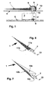
- a generic display device has a pointer which consists of a pointer flag 1 and a pointer axis 2.
- the pointer flag 1 is connected to the pointer axis 2 such that a rotation of the pointer axis 2 deflects the pointer flag 1 over a dial 4 or a scale, whereby the pointer flag 1 fulfills its conventional display function.
- the pointer axis 2 can be driven, for example, by a stepper motor 3 or another suitable drive.
- the stepper motor 3 and its electronic control is usually mounted on a circuit board 5.
- the pointer axis 2 is usually designed to be light-conducting and a light-emitting diode 8 or another light source is placed on the circuit board 5 in such a way that light emitted by this light source is coupled into the pointer axis 2.
- This light is then guided into the pointer flag 1 by a prism head 10 attached to the pointer axis 2 in order to illuminate the pointer flag 1.
- a pointer cap 9 covers the pointer axis 2 on the front.
- the pointer flag 1 has at one end a shaft 7 which is fixedly connected to the pointer flag 1 and is preferably made of steel and which is rotatably mounted in the pointer axis 2, preferably in the prism head 10.
- an at least two-pole actuating magnet 6 is attached to the shaft 7 in order to use it in conjunction with the means shown in FIGS. 2 to 5 to cause the pointer flag 1 to rotate about the axis 13 of its radial extension and to hold the pointer flag 1 in a stable position with respect to the dial 4 serving as a reference plane.
- the actuating magnet 6 can, for example, consist of an annular or disk-shaped, plastic-bonded permanent magnet, in which magnetic poles are embossed at suitable points.
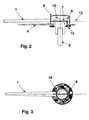
- FIGS. 2 and 3 show sectional representations of a pointer with permanent magnetic adjusting means for the pointer flag 1.
- a permanent magnet 14 which surrounds the pointer axis 2 in a ring is shown, which has at least two differently magnetized segments N and S. Shown are a segment with a magnetization as a magnetic north pole N and a segment with a magnetization as a magnetic south pole S.
- the pointer flag 1 pivots due to the existing between the actuating magnet 6 and the permanent magnet 14 magnetic forces by 180 ° about the axis 13 of their radial extent as soon as the actuating magnet 6 coming from a segment area N is moved over to the other segment area S.
- the pointer flag 1 remains in a certain defined angle of rotation with respect to the axis 13 of its radial extension due to the magnetic attraction forces.
- the pointer flag 1 can perform the function of a detector at that rotational angle position of the pointer axis 2, which is defined by the boundary surfaces of the two segment areas N and S, since the pointer flag 1 has two boundary surfaces which can be distinguished from one another in their appearance.
- the change in appearance can be caused by the fact that the top and bottom of the pointer flag 1 have different colors.
- This embodiment of the invention is of interest, for example, in connection with display devices designed as a tachometer if danger is to be signaled from a certain speed display or if a permissible operating range is to be signaled.
- the permanent magnetic actuators for the pointer flag 1 can also be realized purely mechanical solutions, if it is all about the pointer flag 1 at a certain angle of rotation the pointer axis 2 to rotate about the axis 13 of its radial extent.
- Such mechanical solutions can, for example, by a Gear arrangement and driver structures can be formed function like a roll counter.
- FIGS. 4 and 5 show sectional representations of a pointer with electromagnetic actuating means for the pointer flag 1.
- the pointer consists essentially of the same components as in the exemplary embodiment according to FIGS. 2 and 3. The only difference is that below the dial 4, instead of the permanent magnet 14, there is provided an energizable control coil 15 which surrounds the pointer axis 2 in an annular manner Actuating coil 15 is mounted in a pole guide ring 16 which guides the magnetic field generated by the energization in the direction of the two-pole actuating magnet 6 when the actuating coil 15 is energized.
- the adjusting coil 15 is connected to an electronic control circuit which, however, is not shown in FIGS. 4 and 5.
- the magnetic field between the actuating coil 15 and the actuating magnet 6 can be influenced, so that the pointer flag 1 can be rotated about the axis 13 of its radial extension by the magnetic forces acting on the actuating magnet 6 and can be held in a certain position.
- This rotary movement is independent of the rotation of the pointer flag 1 about the pointer axis 2.
- FIGS. 6 and 7 exemplary embodiments for a pointer flag 1 are shown.
- 6 shows in perspective a pointer flag 1 with two opposing boundary surfaces 11a and 11b.
- FIG. 7 shows in perspective a pointer flag 1 with three boundary surfaces 12a, 12b and 12c, which in this example are arranged in such a way that the cross section of the body of the pointer flag 1 results in an equilateral triangle.
- the pointer flag 1 can, depending on the angle of rotation about the axis 13, of the boundary surfaces 11a, 11b or 12a, 12b and 12c emit different signal effects.
- FIGS. 8A, 8B, 8C and 8D show appearances of the pointer flag 1 at four different angles of rotation of the pointer axis 2.
- the pointer flag 1 moves clockwise over the dial 4, the pointer flag 1 being driven by the pointer axis 2, the pointer flag changes 1 at certain angular positions of the pointer axis 2, its appearance with respect to the boundary surface facing an observer, in this example the pointer flag 1 being designed with three boundary surfaces in accordance with FIG. 7.
- additional information can be reported to the viewer with the pointer flag 1 in addition to the conventional display function of the pointer flag 1 reliably and with a good signal effect.
- the formation of the pointer flag 1 with three boundary surfaces has the advantage that the viewer can also be provided with defined information, for example that a measurement parameter outside of a permissible operating range, through the transition regions in which two boundary surfaces are visible simultaneously as shown in FIG. 8C threatens to run.
- these figures show how a pointer flag 1, depending on its pointer position, conveys additional information to a viewer with good perceptibility quality.
- the pointer flag is about its radial axis Extension by means of a shaft mounted in the pointer axis turned that by a controllable energization of a around the pointer axis ring-shaped adjusting coil a magnetic Field between the control coil and one attached to the pointer flag Magnets trained and due to magnetic attraction or Repulsive forces defined the boundary surfaces of the pointer flag Take position so that a viewer of the display device very certain of these boundary surfaces is facing, whereby the Viewer through that assigned to this boundary surface Appearance of the pointer flag a certain message is conveyed.
- the magnetic field required to rotate the pointer flag is at precise execution of the adjusting coil and the pole guide ring, in which the Control coil is mounted, largely symmetrical.
- the pointer flag begins to rotate. Because with that from the magnetic field resulting torque must also the inevitable bearing friction Wave in the pointer axis can be overcome. On this issue Hardly anything changes when you assume that in practice the magnetic field due to manufacturing and arrangement tolerances be slightly distorted between the control coil and the control magnet like.
- At least one ferromagnetic auxiliary pole be provided through which is between the control coil and the control magnet forming magnetic field is deformed asymmetrically so that already relatively low forces from the magnetic field in of a certain equilibrium position of the positioning magnet in a Can move rotational movement.
- This through the ferromagnetic Auxiliary pole-induced field distortion therefore helps large impulse currents or to avoid excessive current in the control coil in order to avoid this Rotation of the pointer flag to generate the required starting torque.
- the auxiliary pole is arranged in relation to the control magnet that the permanent magnetic field of the control magnet with sufficient intensity can affect the auxiliary pole.
- a current surge in the control coil can cause a Torque can be exerted on the shaft of the pointer flag, so that this begins to rotate until it turns between magnetic field resulting attractive and repulsive forces Forms balance.
- the field of permanent magnetic poles of the Solenoid is primarily aligned to the pole guide ring, what about that leads to the control magnet becoming stable after every half turn Hold position swings.
- the energization of the control coil can accordingly be switched off as soon as the for the wave of the pointer flag Starting torque is applied.
- a in close proximity to the The auxiliary pole arranged in the solenoid is now reduced by that of him caused field distortion to generate the starting torque required electricity.
- This arrangement for a generic The display device thus has a favorable electrical energy balance.
- an auxiliary pole 20 was added to the arrangement shown in FIG. 9 .
- the auxiliary pole 20 consists of a ferromagnetic material and thus has a relative permeability ⁇ r > 1.
- the actuating magnet 6 and auxiliary pole 20 are arranged in such a way that the permanent magnetic field of the actuating magnet 6 can extend to the ferromagnetic auxiliary pole 20 with a sufficient magnetic field strength.
- FIG. 10 shows in a sectional plane AA a pointer with an actuating magnet 6 and an auxiliary pole 20 designed as a pin 21 or rod, the auxiliary pole 20 being positioned in such a way that it is spaced approximately the same distance from the actuating magnet 6 and from the pole guide ring 16. The distance lies approximately between the single to double dimension of the diameter of the pin 21.
- the position of the cutting plane AA can also be seen in connection with the previously explained FIGS. 4 and 9.
- FIG. 11 shows in section plane AA a pointer with an actuating magnet 6 and an auxiliary pole 20 designed as a clip 22.
- This clip 22 can be manufactured as a stamped and bent part from a ferromagnetic material and locked in the pointer cap 9 or above the prism head 10 or there be glued.
- this clip 22 is shown as a single part as a bracket made of a ferromagnetic material.
- a further embodiment of the auxiliary pole 20 can also consist in the fact that the pointer cap 9 is doped with metal fibers made of a ferromagnetic material and is shaped correspondingly towards the actuating magnet 6, so that the auxiliary pole 20 becomes an integral part of the pointer cap 9.
- the pointer cap 9 could also be designed as a ferromagnetic deep-drawn part with a suitable geometry.
- FIG. 13 shows a longitudinal and a rear view of an auxiliary pole 20 designed as a pin 21 or rod.
Abstract
Für eine Anzeigevorrichtung mit einem Zeiger, bei der der Zeiger aus einer drehbaren Zeigerachse 2 und einer an der Zeigerachse 2 radial angeordneten Zeigerfahne 1 besteht, wobei die Zeigerfahne 1 entsprechend einer Drehung der Zeigerachse 2 ausschwenkt, wird vorgeschlagen, daß die Zeigerfahne 1 zusätzlich zu ihrer Schwenkbarkeit infolge der Drehung der Zeigerachse 2 auch um die Achse 13 ihrer radialen Erstreckung drehbar ist und die Zeigerfahne 1 mindestens zwei in ihrem Erscheinungsbild voneinander unterscheidbare Begrenzungsflächen 11a, 11b bzw. 12a, 12b und 12c aufweist. <IMAGE>For a display device with a pointer, in which the pointer consists of a rotatable pointer axis 2 and a pointer flag 1 arranged radially on the pointer axis 2, the pointer flag 1 swiveling out in accordance with a rotation of the pointer axis 2, it is proposed that the pointer flag 1 in addition to it Swiveling as a result of the rotation of the pointer axis 2 can also be rotated about the axis 13 of its radial extension and the pointer flag 1 has at least two boundary surfaces 11a, 11b or 12a, 12b and 12c which can be distinguished from one another in their appearance. <IMAGE>
Description
Die Erfindung betrifft eine Anzeigevorrichtung mit einem Zeiger nach dem Oberbegriff des ersten Anspruchs. Bei dieser Anzeigevorrichtung besteht der Zeiger aus einer drehbaren Zeigerachse und einer an der Zeigerachse radial angeordneten Zeigerfahne, wobei die Zeigerfahne entsprechend einer Drehung der Zeigerachse ausschwenkt.The invention relates to a display device with a pointer according to the Preamble of the first claim. In this display device there is Pointer consisting of a rotatable pointer axis and a radial one on the pointer axis arranged pointer flag, the pointer flag corresponding to a Pivot rotation of the pointer axis.
Derartige Anzeigevorrichtungen sind durch vielfältige Benutzung hinlänglich bekannt. Sie finden sich beispielsweise in Anzeigeinstrumenten in Fahrzeugen. Bei diesen Anzeigevorrichtungen ist die Zeigerfahne starr mit der Zeigerachse verbunden. Bei manchen Ausführungen ist die Zeigerfahne als Lichtleiter ausgebildet und kann im Bedarfsfall beleuchtet werden. Es hat sich jedoch herausgestellt, daß eine derart beleuchtete Zeigerfahne bei hellem Umgebungslicht nur einen geringen Kontrast aufweist und infolge dessen in bestimmten Situationen auch nur eine schwache Signalwirkung entfaltet, so daß eine Zeigerfahne dieser Bauart wenig geeignet ist, zusätzlich zu ihrer herkömmlichen Anzeigefunktion die Funktion eines Melders zuverlässig zu übernehmen, selbst wenn man in die als Lichtleiter ausgebildete Zeigerfahne zur Anzeige einer bestimmten Meldung Licht unterschiedlicher Farbe oder Intensität einspeisen würde. Auch sind Ausgestaltungen von gattungsgemäßen Anzeigevorrichtungen mit einer mit einem Farbauftrag versehenen Zeigerfahne bekannt, jedoch geht von einer starr mit der Zeigerachse verbundenen Zeigerfahne mit einer dauerhaften, unveränderbaren farbigen Oberflächengestaltung an sich keine für einen Melder nutzbare Signalwirkung aus. Such display devices are sufficient due to their diverse use known. They can be found, for example, in display instruments in Vehicles. The pointer flag is rigid with these display devices connected to the pointer axis. In some versions the pointer flag is trained as a light guide and can be illuminated if necessary. It has it turned out, however, that such an illuminated pointer flag at bright ambient light has only a low contrast and as a result which in certain situations is only a weak signal unfolded, so that a pointer flag of this type is not very suitable, in addition to their conventional display function, the function of a Detector to take over reliably, even if you are in the light guide trained pointer flag to indicate a specific message light of different color or intensity. Also are Refinements of generic display devices with a known pointer flag provided, but goes from one pointer flag rigidly connected to the pointer axis with a permanent, unchangeable colored surface design per se not for one Detector usable signal effect.
Es ist nun die Aufgabe der vorliegenden Erfindung, eine gattungsgemäße Anzeigevorrichtung mit einem Zeiger derart weiterzuentwickeln, daß die Zeigerfahne zusätzlich zu ihrer herkömmlichen Anzeigefunktion zuverlässig und mit ausreichender Signalwirkung als Melder nutzbar ist.It is now the object of the present invention, a generic Develop display device with a pointer such that the Pointer flag reliable in addition to its conventional display function and can be used as a detector with sufficient signal effect.
Gelöst wird die Aufgabe durch eine Anzeigevorrichtung mit einem Zeiger mit den Merkmalen des ersten Anspruchs, insbesondere dadurch, daß die Zeigerfahne zusätzlich zu ihrer Schwenkbarkeit infolge der Drehung der Zeigerachse auch um die Achse ihrer radialen Erstreckung drehbar ist und die Zeigerfahne mindestens zwei in ihrem Erscheinungsbild voneinander unterscheidbare Begrenzungsflächen aufweist. Die Lösung sieht demnach vor, daß die Begrenzungsflächen der Zeigerfahne zur Darstellung von mindestens zwei deutlich voneinander unterscheidbaren Signalzuständen genutzt werden. Entsprechend dem Drehwinkel der Zeigerfahne um die Achse ihrer radialen Erstreckung geht von den Begrenzungsflächen der Zeigerfahne somit eine Signalwirkung aus, so daß die Zeigerfahne zusätzlich zu ihrer herkömmlichen Anzeigefunktion als Melder nutzbar ist.The task is solved by a display device with a pointer the features of the first claim, in particular in that the Pointer flag in addition to its pivotability due to the rotation of the Pointer axis is also rotatable about the axis of its radial extent and the pointer flag at least two in appearance has distinguishable boundary surfaces. The solution looks accordingly before that the boundary surfaces of the pointer flag to represent at least two clearly distinguishable signal states be used. According to the angle of rotation of the pointer flag around The axis of their radial extension goes from the boundary surfaces of the The pointer flag thus has a signal effect, so that the pointer flag additionally can be used as a detector for their conventional display function.
Die abhängigen Ansprüche zeigen Ausgestaltungen und Weiterbildungen der gefundenen Lösung. So kann die Anzeigevorrichtung derart ausgestaltet sein, daß die Drehung der Zeigerfahne um die Achse ihrer radialen Erstreckung von der Drehung der Zeigerachse unabhängig ist. Es besteht demnach keine Kopplung zwischen dem Drehwinkel der Zeigerachse und dem Drehwinkel der Zeigerfahne. Eine solche Ausgestaltung hat den Vorteil, daß die Funktion der Zeigerfahne als Melder unabhängig von der herkömmlichen Anzeigefunktion der Zeigerfahne ausgeführt werden kann.The dependent claims show refinements and developments of found solution. The display device can be configured in this way be that the rotation of the pointer flag around the axis of its radial Extension is independent of the rotation of the pointer axis. It exists therefore no coupling between the angle of rotation of the pointer axis and the angle of rotation of the pointer flag. Such an embodiment has the advantage that the function of the pointer flag as a detector regardless of the conventional display function of the pointer flag can be performed.
Als Antrieb zum Drehen der Zeigerfahne um die Achse ihrer radialen Erstreckung eignen sich insbesondere permanentmagnetische oder elektromagnetische Stellmittel, weil sie kostengünstig zu realisieren sind. Dabei können die permanentmagnetischen Stellmittel beispielsweise aus einem an einer Welle der Zeigerfahne angeordneten zweipoligen Stellmagneten und einem um die Zeigerachse ringförmig ausgebildeten Permanentmagneten mit mindestens zwei unterschiedlichen Polaritätszonen bestehen. Elektromagnetische Stellmittel kann man aus einem an einer Welle der Zeigerfahne angeordneten zweipoligen Stellmagneten und einer um die Zeigerachse ringförmig ausgebildeten bestrombaren Stellspule ausbilden. Die Verwendung von permanentmagnetischen Stellmitteln ist dann eine einfach und kostengünstig zu realisierende Lösung, wenn die Funktion der Zeigerfahne als Melder in fester Abhängigkeit von einem bestimmten Drehwinkel der Zeigerachse erfolgen soll. Wenn die Funktion der Zeigerfahne als Melder unabhängig vom Drehwinkel der Zeigerachse steuerbar sein soll, sind elektromagnetische Stellmittel, bei denen der Stromfluß durch eine Stellspule im Sinne des Meldesignals steuerbar ist, das adäquate Lösungsmittel. Für die konstruktive Ausgestaltung ist es vorteilhaft, wenn die Welle der Zeigerfahne in der Zeigerachse selbst oder in deren mit ihr fest verbundenen Verlängerung drehbar gelagert ist. Die Welle der Zeigerfahne ist mit dem Körper der Zeigerfahne fest verbunden.As a drive for rotating the pointer flag around the axis of its radial Extension are particularly suitable for permanent magnetic or electromagnetic actuators because they are inexpensive to implement. The permanent magnetic actuating means can, for example, consist of a two-pole arranged on a shaft of the pointer flag Setting magnet and a ring-shaped around the pointer axis Permanent magnets with at least two different polarity zones consist. Electromagnetic actuators can be turned from one to one Shaft of the pointer flag arranged two-pole actuating magnet and one energizable control coil formed in a ring around the pointer axis form. The use of permanent magnetic actuators a simple and inexpensive solution to implement if the Function of the pointer flag as a detector depending on one certain rotation angle of the pointer axis is to take place. If the function of the Pointer flag as detector regardless of the angle of rotation of the pointer axis should be controllable are electromagnetic actuators, in which the Current flow through an adjusting coil in the sense of the message signal is controllable adequate solvent. For the structural design, it is advantageous if the shaft of the pointer flag in the pointer axis itself or in its axis its firmly connected extension is rotatably mounted. The wave of The pointer flag is firmly connected to the body of the pointer flag.
Um die Zeigerfahne zusätzlich zu ihrer herkömmlichen Anzeigefunktion als Melder zu nutzen, kann die Zeigerfahne entlang der Achse ihrer radialen Erstreckung mindestens zwei Begrenzungsflächen aufweisen, die sich in ihrer Farbgebung voneinander unterscheiden. Durch zwei sich signifikant unterscheidende Farben wie beispielsweise rot und grün werden zwei deutlich voneinander unterscheidbare Signalzustände bereitgestellt, die bei entsprechend fest vereinbarter Zuordnung zur Meldung in einfach zu interpretierender Weise signalisieren, ob beispielsweise die bestimmte Meldung vorliegt oder nicht. Dabei können die mindestens zwei Begrenzungsflächen der Zeigerfahne einen unterschiedlichen Farbauftrag aufweisen. Ein Farbauftrag läßt sich drucktechnisch oder durch eine entsprechende Lackierung einfach und kostengünstig realisieren, sofern der Werkstoff und die Oberflächenbeschaffenheit der Zeigerfahne für derartige Behandlungen geeignet sind. Eine Alternative zum Farbauftrag auf der Zeigerfahne besteht darin, die Zeigerfahne als einen Farbwandler auszubilden, bei dem die Begrenzungsflächen der Zeigerfahne mit einem Fluoreszenzdruck versehen sind, so daß die Begrenzungsflächen erst bei Anstrahlung mit UV-Licht einen zum unbestrahlten Zustand veränderten Farbeindruck erhalten. Sofern die Zeigerfahne als Lichtleiter ausgebildet ist, können die Begrenzungsflächen der Zeigerfahne auch derart beschaffen sein, daß in die Zeigerfahne eingekoppeltes Licht je nach Drehwinkel der Zeigerfahne um die Achse ihrer radialen Erstreckung einen unterschiedlichen optischen Eindruck hervorruft, so daß für einen Betrachter beispielsweise entweder die Grundfarbe des Körpers der Zeigerfahne bzw. die auf deren Begrenzungsflächen aufgetragene Farbe überwiegt oder die Farbe des in die Zeigerfahne eingekoppelten und an den Begrenzungsflächen der Zeigerfahne austretenden Lichtes.To the pointer flag in addition to its conventional display function as To use detectors, the pointer flag can be along the axis of its radial Extend at least two boundary surfaces, which are in differ from each other in their coloring. Significantly by two distinguishing colors such as red and green become two signal states that are clearly distinguishable from each other according to a fixed assignment to the message in easy to interpretively signal whether, for example, the particular There is a message or not. The at least two Boundary surfaces of the pointer flag a different color application exhibit. A color application can be done by printing or by a realize appropriate painting easily and inexpensively, provided that Material and the surface condition of the pointer flag for such Treatments are suitable. An alternative to applying paint on the Pointer flag consists of using the pointer flag as a color converter form, in which the boundary surfaces of the pointer flag with a Fluorescence printing are provided so that the boundary surfaces only at Illumination with UV light changed to an unirradiated state Get color impression. If the pointer flag is designed as a light guide, can also obtain the boundary surfaces of the pointer flag in this way be that light coupled into the pointer flag depending on the angle of rotation of the Pointer flag around the axis of its radial extension a different produces an optical impression, so that, for example, for a viewer either the basic color of the body of the pointer flag or that of the pointer flag Boundary color applied predominates or the color of the in the Pointer flag coupled and on the boundary surfaces of the Pointer flag of emerging light.
Anhand von dreizehn Figuren soll die Erfindung nun noch näher erläutert werden. Dabei zeigen
-
Figur 1 - schematisch den prinzipiellen Aufbau einer gattungsgemäßen Anzeigevorrichtung,
-
Figur 2 - einen Längsschnitt eines Zeigers mit permanentmagnetischen Stellmitteln für die Zeigerfahne,
-
Figur 3 - eine Draufsicht eines Zeigers mit permanentmagnetischen Stellmitteln für die Zeigerfahne,
-
Figur 4 - einen Längsschnitt eines Zeigers mit elektromagnetischen Stellmitteln für die Zeigerfahne,
-
Figur 5 - eine Draufsicht eines Zeigers mit elektromagnetischen Stellmitteln für die Zeigerfahne,
-
Figur 6 - perspektivisch eine Zeigerfahne mit zwei Begrenzungsflächen,
-
Figur 7 - perspektivisch eine Zeigerfahne mit drei Begrenzungsflächen,
- Figur 8A bis 8D
- eine Serie von Erscheinungsbildern der Zeigerfahne bei vier unterschiedlichen Drehwinkeln der Zeigerachse,
-
Figur 9 - eine Draufsicht eines Zeigers mit einem Stellmagneten und einem Hilfspol,
-
Figur 10 - einen Längsschnitt eines Zeigers mit einem Stellmagneten und einem stiftartigen Hilfspol,
-
Figur 11 - einen Längsschnitt eines Zeigers mit einem Stellmagneten und einem als Clip ausgebildeten Hilfspol,
- Figur 12
- einen als Clip ausgebildeten Hilfspols als Einzelteil und
-
Figur 13 - zwei Detailansichten des stiftartigen Hilfspols.
- Figure 1
- schematically the basic structure of a generic display device,
- Figure 2
- a longitudinal section of a pointer with permanent magnetic adjusting means for the pointer flag,
- Figure 3
- a plan view of a pointer with permanent magnetic adjusting means for the pointer flag,
- Figure 4
- 2 shows a longitudinal section of a pointer with electromagnetic setting means for the pointer flag,
- Figure 5
- a plan view of a pointer with electromagnetic adjusting means for the pointer flag,
- Figure 6
- perspective a pointer flag with two boundary surfaces,
- Figure 7
- perspectively a pointer flag with three boundary surfaces,
- Figure 8A to 8D
- a series of appearances of the pointer flag at four different angles of rotation of the pointer axis,
- Figure 9
- a plan view of a pointer with an actuating magnet and an auxiliary pole,
- Figure 10
- 2 shows a longitudinal section of a pointer with an actuating magnet and a pin-like auxiliary pole,
- Figure 11
- 2 shows a longitudinal section of a pointer with an adjusting magnet and an auxiliary pole designed as a clip,
- Figure 12
- an auxiliary pole designed as a clip as a single part and
- Figure 13
- two detailed views of the pin-like auxiliary pole.
Gemäß der Figur 1 besitzt eine gattungsgemäße Anzeigevorrichtung einen
Zeiger, der aus einer Zeigerfahne 1 und einer Zeigerachse 2 besteht. Die
Zeigerfahne 1 ist mit der Zeigerachse 2 derart verbunden, daß eine Drehung
der Zeigerachse 2 die Zeigerfahne 1 über einem Zifferblatt 4 oder einer Skala
auslenkt, wodurch die Zeigerfahne 1 ihre herkömmliche Anzeigefunktion
erfüllt. Die Zeigerachse 2 kann zum Beispiel von einem Schrittmotor 3 oder
einem anderen geeigneten Antrieb angetrieben werden. Der Schrittmotor 3
und dessen elektronische Ansteuerung ist in der Regel auf einer Leiterplatte
5 montiert. Für kraftfahrtechnische Anwendungen ist die Zeigerachse 2
zumeist Licht leitend ausgebildet und eine Leuchtdiode 8 oder ein anderes
Leuchtmittel ist derart auf der Leiterplatte 5 plaziert, daß von diesem
Leuchtmittel ausgesandtes Licht in die Zeigerachse 2 eingekoppelt wird.
Durch einen an der Zeigerachse 2 angebrachten Prismenkopf 10 wird dann
dieses Licht in die Zeigerfahne 1 geleitet, um die Zeigerfahne 1 zu
beleuchten. Eine Zeigerkappe 9 deckt frontseitig die Zeigerachse 2 ab. Die
Zeigerfahne 1 weist an ihrem einen Ende eine fest mit der Zeigerfahne 1
verbundene, vorzugsweise aus Stahl gefertigte Welle 7 auf, welche in der
Zeigerachse 2, vorzugsweise im Prismenkopf 10, drehbar gelagert ist.
Überdies ist an der Welle 7 erfindungsgemäß ein mindestens zweipoliger
Stellmagnet 6 angebracht, um mit dessen Hilfe in Verbindung mit den in den
Figuren 2 bis 5 aufgezeigten Mitteln eine Drehbewegung der Zeigerfahne 1
um die Achse 13 ihrer radialen Erstreckung zu bewirken sowie das Halten
der Zeigerfahne 1 in einer stabilen Position gegenüber dem als Bezugsebene
dienenden Zifferblatt 4. Der Stellmagnet 6 kann beispielsweise aus einem
ringförmigen bzw. scheibenförmigen kunststoffgebundenen
Permanentmagneten bestehen, in dem an geeigneten Stellen magnetische
Pole eingeprägt sind.According to FIG. 1 , a generic display device has a pointer which consists of a
Die Figuren 2 und 3 zeigen Schnittdarstellungen eines Zeigers mit
permanentmagnetischen Stellmitteln für die Zeigerfahne 1. Ergänzend zur
Figur 1 ist ein die Zeigerachse 2 ringförmig umschließender
Permanentmagnet 14 dargestellt, der mindestens zwei unterschiedlich
magnetisierte Segmente N und S aufweist. Dargestellt sind ein Segment mit
einer Magnetisierung als magnetischer Nordpol N und ein Segment mit einer
Magnetisierung als magnetischer Südpol S. Wenn nun die Zeigerfahne 1 mit
dem an der Welle 7 angebrachten Stellmagneten 6 - angetrieben von der
Zeigerachse 2 - über den ringförmigen Permanentmagneten 14 hinweg
bewegt wird, schwenkt die Zeigerfahne 1 infolge der zwischen dem
Stellmagneten 6 und dem Permanentmagneten 14 bestehenden
magnetischen Kräfte um 180° um die Achse 13 ihrer radialen Erstreckung,
sobald der Stellmagnet 6 vom einen Segmentbereich N kommend zum
anderen Segmentbereich S hinüber bewegt wird. Solange sich der
Stellmagnet 6 in Wirkverbindung mit dem einen oder dem anderen
Segmentbereich befindet, verharrt die Zeigerfahne 1 aufgrund der
magnetischen Anziehungskräfte in einem bestimmten definierten Drehwinkel
bezüglich der Achse 13 ihrer radialen Erstreckung. Auf diese Weise kann die
Zeigerfahne 1 an derjenigen Drehwinkelposition der Zeigerachse 2, die durch
die Grenzflächen der beiden Segmentbereiche N und S definiert ist, die
Funktion eines Melders ausüben, da die Zeigerfahne 1 zwei in ihrem
Erscheinungsbild voneinander unterscheidbare Begrenzungsflächen
aufweist. Die Veränderung des Erscheinungsbildes kann dadurch
hervorgerufen werden, daß die Oberseite und die Unterseite der Zeigerfahne
1 farblich unterschiedlich gestaltet sind. Diese Ausgestaltung der Erfindung
ist beispielsweise in Verbindung mit als Drehzahlmesser ausgebildeten
Anzeigevorrichtungen interessant, wenn ab einer bestimmten
Drehzahlanzeige Gefahr oder das Verlassen eines zulässigen
Betriebsbereiches signalisiert werden soll.FIGS. 2 and 3 show sectional representations of a pointer with permanent magnetic adjusting means for the
Alternativ zu den hier beschriebenen permanentmagnetischen Stellmitteln für
die Zeigerfahne 1 sind auch rein mechanische Lösungen realisierbar, wenn
es allein darum geht, die Zeigerfahne 1 bei einem bestimmten Drehwinkel
der Zeigerachse 2 um die Achse 13 ihrer radialen Erstreckung zu drehen.
Derartige mechanische Lösungen können beispielsweise durch eine
Zahnradanordnung und Mitnehmerkonstruktionen ausgebildet sein, die
ähnlich einem Rollenzählwerk funktionieren.As an alternative to the permanent magnetic actuators for
the
In den Figuren 4 und 5 sind Schnittdarstellungen eines Zeigers mit
elektromagnetischen Stellmitteln für die Zeigerfahne 1 dargestellt. Dabei
besteht der Zeiger im wesentlichen aus den gleichen Bauelementen wie bei
dem Ausführungsbeispiel gemäß den Figuren 2 und 3. Ein Unterschied
besteht allein darin, daß unterhalb des Zifferblattes 4 statt des
Permanentmagneten 14 eine die Zeigerachse 2 ringförmig umschließende
bestrombare Stellspule 15 vorgesehen ist, wobei die Stellspule 15 in einem
Polführungsring 16 gelagert ist, der bei Bestromung der Stellspule 15 das
durch die Bestromung erzeugte Magnetfeld in Richtung des zweipoligen
Stellmagnaten 6 leitet. Die Stellspule 15 ist mit einer elektronischen
Steuerschaltung verbunden, die in den Figuren 4 und 5 jedoch nicht
dargestellt ist. Mittels dieser Steuerschaltung kann auf das Magnetfeld
zwischen der Stellspule 15 und dem Stellmagnaten 6 Einfluß genommen
werden, so daß die Zeigerfahne 1 durch die am Stellmagnaten 6 wirkenden
magnetischen Kräfte um die Achse 13 ihrer radialen Erstreckung gedreht und
in einer bestimmten Position gehalten werden kann. Diese Drehbewegung ist
unabhängig von der Drehung der Zeigerfahne 1 um die Zeigerachse 2.FIGS. 4 and 5 show sectional representations of a pointer with electromagnetic actuating means for the
In den Figur 6 und 7 sind Ausführungsbeispiele für eine Zeigerfahne 1
dargestellt. So zeigt Figur 6 perspektivisch eine Zeigerfahne 1 mit zwei sich
gegenüber liegenden Begrenzungsflächen 11a und 11b. Die Figur 7 zeigt
perspektivisch eine Zeigerfahne 1 mit drei Begrenzungsflächen 12a, 12b und
12c, die in diesem Beispiel derart zueinander angeordnet sind, daß der
Querschnitt des Körpers der Zeigerfahne 1 ein gleichseitiges Dreieck ergibt.
Durch Drehung der Zeigerfahne 1 um die Achse 13 ihrer radialen
Erstreckung wird dem Betrachter jeweils mindestens eine der
Begrenzungsflächen 11a, 11b bzw. 12a, 12b und 12c zugewandt. Wenn die
Begrenzungsflächen 11a, 11b bzw. 12a, 12b und 12c beispielsweise durch
Farbdrucke in ihrem Erscheinungsbild voneinander verschieden gestaltet
sind, können von den Begrenzungsflächen 11 a, 11b bzw. 12a, 12b und 12c
der Zeigerfahne 1 je nach dem Drehwinkel um die Achse 13 unterschiedliche
Signalwirkungen ausgehen.In FIGS. 6 and 7 , exemplary embodiments for a
Die Figuren 8A, 8B, 8C und 8D zeigen Erscheinungsbilder der Zeigerfahne
1 bei vier unterschiedlichen Drehwinkeln der Zeigerachse 2. Während sich
die Zeigerfahne 1 im Uhrzeigersinn über das Zifferblatt 4 hinweg bewegt,
wobei die Zeigerfahne 1 von der Zeigerachse 2 angetrieben wird, ändert die
Zeigerfahne 1 bei bestimmten Winkelstellungen der Zeigerachse 2 ihr
Erscheinungsbild bezüglich der einem Betrachter zugewandten
Begrenzungsfläche, wobei in diesem Beispiel die Zeigerfahne 1
entsprechend der Figur 7 mit drei Begrenzungsflächen ausgebildet ist.
Dadurch kann dem Betrachter mit der Zeigerfahne 1 zusätzlich zu der
herkömmlichen Anzeigefunktion der Zeigerfahne 1 zuverlässig und mit guter
Signalwirkung eine weitere Information gemeldet werden. Die Ausbildung der
Zeigerfahne 1 mit drei Begrenzungsflächen hat den Vorteil, daß dem
Betrachter auch durch die Übergangsbereiche, in denen entsprechend der
Darstellung in der Figur 8C zwei Begrenzungsfläche gleichzeitig sichtbar
sind, eine definierte Information vermittelt werden kann, beispielsweise daß
ein Meßparameter außerhalb eines zulässigen Betriebsbereiches zu laufen
droht. Zusammenfassend zeigen diese Figuren, wie eine Zeigerfahne 1 in
Abhängigkeit von ihrer Zeigerposition in guter Wahrnehmbarkeitsqualität eine
Zusatzinformation an einen Betrachter vermittelt. FIGS. 8A, 8B, 8C and 8D show appearances of the
Im nun folgenden Teil der Erfindungsbeschreibung wird noch eine
Weiterentwicklung der bisher erörterten Lösung beschrieben. Ausgangspunkt
dieser Weiterbildung ist eine Anzeigevorrichtung mit einem Zeiger,
Wie zuvor schon erläutert, wird die Zeigerfahne um die Achse ihrer radialen Erstreckung mittels einer in der Zeigerachse gelagerten Welle dadurch gedreht, daß sich durch eine bedarfsgerecht steuerbare Bestromung einer um die Zeigerachse ringförmig ausgebildeten Stellspule ein magnetisches Feld zwischen der Stellspule und einem an der Zeigerfahne befestigten Stellmagneten ausbildet und aufgrund von magnetischen Anziehungs- bzw. Abstoßungskräften die Begrenzungsflächen der Zeigerfahne eine definierte Position einnehmen, so daß einem Betrachter der Anzeigevorrichtung eine ganz bestimmte dieser Begrenzungsflächen zugewandt wird, wodurch dem Betrachter durch das dieser Begrenzungsfläche zugeordnete Erscheinungsbild der Zeigerfahne eine bestimmte Meldung vermittelt wird. As previously explained, the pointer flag is about its radial axis Extension by means of a shaft mounted in the pointer axis turned that by a controllable energization of a around the pointer axis ring-shaped adjusting coil a magnetic Field between the control coil and one attached to the pointer flag Magnets trained and due to magnetic attraction or Repulsive forces defined the boundary surfaces of the pointer flag Take position so that a viewer of the display device very certain of these boundary surfaces is facing, whereby the Viewer through that assigned to this boundary surface Appearance of the pointer flag a certain message is conveyed.
Nun ist das zur Drehung der Zeigerfahne erforderliche magnetische Feld bei präziser Ausführung der Stellspule und des Polführungsrings, in dem die Stellspule gelagert ist, weitgehend symmetrisch. In der Folge ist zur Drehung der Zeigerfahne ein relativ starkes magnetisches Feld erforderlich, um auf den Stellmagneten ein ausreichend großes Drehmoment einwirken zu lassen, damit sich dieser samt der mit ihm über die Welle starr verbundenen Zeigerfahne zu drehen beginnt. Denn mit dem aus dem magnetischen Feld resultierenden Drehmoment muß auch die unvermeidbare Lagerreibung der Welle in der Zeigerachse überwunden werden. An diesem Sachverhalt ändert sich auch kaum etwas, wenn man davon ausgeht, daß in der Praxis infolge von Fertigungs- und Anordnungstoleranzen das magnetische Feld zwischen der Stellspule und dem Stellmagneten geringfügig verzerrt sein mag.Now the magnetic field required to rotate the pointer flag is at precise execution of the adjusting coil and the pole guide ring, in which the Control coil is mounted, largely symmetrical. As a result, it turns the pointer flag required a relatively strong magnetic field to the actuating magnets have a sufficiently large torque so that it can be rigidly connected to it via the shaft The pointer flag begins to rotate. Because with that from the magnetic field resulting torque must also the inevitable bearing friction Wave in the pointer axis can be overcome. On this issue Hardly anything changes when you assume that in practice the magnetic field due to manufacturing and arrangement tolerances be slightly distorted between the control coil and the control magnet like.
Um das aus dem magnetischen Feld zwischen der Stellspule und dem Stellmagneten zu erzeugende Drehmoment, welches zur Drehung der Zeigerfahne erforderlich ist, zu erhöhen, wird in dieser Weiterbildung nun vorgeschlagen, daß mindestens ein ferromagnetischer Hilfspol vorgesehen wird, durch den das sich zwischen der Stellspule und dem Stellmagneten ausbildende magnetische Feld derart unsymmetrisch verformt wird, daß bereits verhältnismäßig geringe Kräfte aus dem magnetischen Feld den in einer bestimmten Gleichgewichtsposition verharrenden Stellmagneten in eine Drehbewegung versetzen können. Diese durch den ferromagnetischen Hilfspol hervorgerufene Feldverzerrung hilft demnach, große Impulsströme oder Stromüberhöhungen in der Stellspule zu vermeiden, um das zur Drehung der Zeigerfahne erforderliche Anlaufdrehmoment zu erzeugen. Dabei wird der Hilfspol derart im Verhältnis zum Stellmagneten angeordnet, daß sich das permanentmagnetische Feld des Stellmagneten mit ausreichender Intensität auf den Hilfspol auswirken kann.To that from the magnetic field between the control coil and the Actuator to generate torque, which is used to rotate the Pointer flag is required to increase, is in this training now proposed that at least one ferromagnetic auxiliary pole be provided through which is between the control coil and the control magnet forming magnetic field is deformed asymmetrically so that already relatively low forces from the magnetic field in of a certain equilibrium position of the positioning magnet in a Can move rotational movement. This through the ferromagnetic Auxiliary pole-induced field distortion therefore helps large impulse currents or to avoid excessive current in the control coil in order to avoid this Rotation of the pointer flag to generate the required starting torque. The auxiliary pole is arranged in relation to the control magnet that the permanent magnetic field of the control magnet with sufficient intensity can affect the auxiliary pole.
Ein zweipoliger Stellmagnet nimmt zur Stellspule zwei bestimmte Winkelpositionen ein, die hier beispielhaft mit ϕ1 = 0° und ϕ2 = 180° bezeichnet werden. Durch einen Stromstoß in der Stellspule kann ein Drehmoment auf die Welle der Zeigerfahne ausgeübt werden, so daß sich diese zu drehen beginnt, bis sich wieder zwischen den aus dem magnetischen Feld resultierenden Anziehungs- und Abstoßungskräften ein Gleichgewicht ausbildet. Das Feld der dauermagnetischen Pole des Stellmagneten richtet sich vorrangig zum Polführungsring hin aus, was dazu führt, daß der Stellmagnet nach jeder halben Umdrehung in eine stabile Halteposition einschwenkt. Die Bestromung der Stellspule kann demnach ausgeschaltet werden, sobald für die Welle der Zeigerfahne das Anlaufdrehmoment aufgebracht ist. Ein in räumlicher Nähe zum Stellmagneten angeordneter Hilfspol reduziert nun durch die von ihm bewirkte Feldverzerrung den zur Erzeugung des Anlaufdrehmoments erforderlichen Strom. Diese Anordnung für eine gattungsgemäße Anzeigevorrichtung weist somit eine günstige elektrische Energiebilanz auf.A two-pole control magnet takes two specific ones for the control coil Angular positions, which here are exemplary with ϕ1 = 0 ° and ϕ2 = 180 ° be designated. A current surge in the control coil can cause a Torque can be exerted on the shaft of the pointer flag, so that this begins to rotate until it turns between magnetic field resulting attractive and repulsive forces Forms balance. The field of permanent magnetic poles of the Solenoid is primarily aligned to the pole guide ring, what about that leads to the control magnet becoming stable after every half turn Hold position swings. The energization of the control coil can accordingly be switched off as soon as the for the wave of the pointer flag Starting torque is applied. A in close proximity to the The auxiliary pole arranged in the solenoid is now reduced by that of him caused field distortion to generate the starting torque required electricity. This arrangement for a generic The display device thus has a favorable electrical energy balance.
Mit in der Stellspule fließenden Dauerströmen unterschiedlicher Stärke lassen sich unter Einbeziehung des vom Hilfspol beeinflußten magnetischen Feldes auch verschiedene Drehwinkel für die Zeigerfahne einstellen. Beispielsweise mag die Zeigerfahne bei unbestromter Stellspule den Drehwinkel α = 0° einnehmen. Bei einer Stromstärke +1 mag sich dann die Zeigerfahne ― ausgehend von ihrer Ruhelage mit dem Drehwinkel α = 0° - um den Drehwinkel β = +120° drehen und, wenn durch Änderung der Stromrichtung die Stromstärke -I eingestellt wird, um den Drehwinkel y = -120°. Auf diese Weise kann eine mit drei Begrenzungsflächen ausgebildete Zeigerfahne in 120° - Schritten gedreht werden.With continuous currents of different strengths flowing in the control coil can be influenced by the magnetic influence of the auxiliary pole Field also set different angles of rotation for the pointer flag. For example, the pointer flag may be the when the actuator coil is not energized Take angle of rotation α = 0 °. At a current of +1, then the Pointer flag - starting from its rest position with the angle of rotation α = 0 ° - turn by the angle of rotation β = + 120 ° and, if by changing the Current direction the current strength -I is set to the angle of rotation y = -120 °. In this way, one with three boundary surfaces trained pointer flag can be rotated in 120 ° steps.
Aufbauend auf den bereits erörterten Figuren 1, 4 und 5 soll die vorgeschlagene Weiterbildung nun im wesentlichen noch anhand der Figuren 9 bis 13 näher erläutert werden.Building on the already discussed Figures 1, 4 and 5, the Proposed further development is now essentially based on the figures 9 to 13 are explained in more detail.
In der Figur 9 wurde der in der Figur 5 gezeigten Anordnung ein Hilfspol 20
hinzugefügt. Der Hilfspol 20 besteht aus einem ferromagnetischen Werkstoff
und hat damit eine relative Permeabilität µr > 1. Stellmagnet 6 und Hilfspol 20
sind derart zueinander angeordnet, daß sich das dauermagnetische Feld des
Stellmagneten 6 mit ausreichender magnetischer Feldstärke auf den
ferromagnetischen Hilfspol 20 erstrecken kann.In FIG. 9 , an
Die Figur 10 zeigt in einer Schnittebene A-A einen Zeiger mit einem
Stellmagneten 6 und einem als Stift 21 oder Stab ausgebildeten Hilfspol 20,
wobei der Hilfspol 20 derart positioniert ist, daß er vom Stellmagneten 6 und
vom Polführungsring 16 in etwa gleich weit beabstandet ist. Der Abstand liegt
dabei etwa zwischen dem einfachen bis doppelten Maß des Durchmessers
des Stiftes 21. Die Lage der Schnittebene A-A kann auch in Verbindung mit
den zuvor erläuterten Figuren 4 und 9 ersehen werden. FIG. 10 shows in a sectional plane AA a pointer with an
Die Figur 11 zeigt in der Schnittebene A-A einen Zeiger mit einem
Stellmagneten 6 und einem als Clip 22 ausgebildeten Hilfspol 20. Dieser Clip
22 kann als ein Stanz-Biegeteil aus einem ferromagnetischen Werkstoff
gefertigt und in der Zeigerkappe 9 oder über dem Prismenkopf 10 verrastet
oder dort verklebt werden. In der Figur 12 ist dieser Clip 22 als Einzelteil als
ein Bügel aus einem ferromagnetischen Werkstoff dargestellt. Eine weitere
Ausbildung des Hilfspols 20 kann auch darin bestehen, daß die Zeigerkappe
9 mit Metallfasern aus einem ferromagnetischen Werkstoff dotiert und gerade
zum Stellmagneten 6 hin entsprechend ausgeformt wird, so daß der Hilfspol
20 zu einem integralen Bestandteil der Zeigerkappe 9 wird. So könnte die
Zeigerkappe 9 auch als ein ferromagnetisches Tiefziehteil mit einer
passenden Geometrie ausgebildet sein. Die Figur 13 zeigt eine Längs- und
eine Rückansicht eines als Stift 21 oder Stab ausgebildeten Hilfspols 20. FIG. 11 shows in section plane AA a pointer with an
Claims (15)
Applications Claiming Priority (4)
| Application Number | Priority Date | Filing Date | Title |
|---|---|---|---|
| DE2000108211 DE10008211A1 (en) | 2000-09-06 | 2000-02-23 | Indicating instrument, using pointer which can rotate about its own axis |
| DE10008211 | 2000-02-23 | ||
| DE10043950A DE10043950A1 (en) | 2000-02-23 | 2000-09-06 | Display device with a pointer |
| DE10043950 | 2000-09-06 |
Publications (2)
| Publication Number | Publication Date |
|---|---|
| EP1128166A2 true EP1128166A2 (en) | 2001-08-29 |
| EP1128166A3 EP1128166A3 (en) | 2002-01-09 |
Family
ID=26004475
Family Applications (1)
| Application Number | Title | Priority Date | Filing Date |
|---|---|---|---|
| EP01103912A Withdrawn EP1128166A3 (en) | 2000-02-23 | 2001-02-17 | Pointer type indicator |
Country Status (4)
| Country | Link |
|---|---|
| US (1) | US6470822B2 (en) |
| EP (1) | EP1128166A3 (en) |
| BR (1) | BR0100472A (en) |
| DE (1) | DE10043950A1 (en) |
Families Citing this family (20)
| Publication number | Priority date | Publication date | Assignee | Title |
|---|---|---|---|---|
| AUPQ592700A0 (en) * | 2000-02-29 | 2000-03-23 | Australian Arrow Pty Ltd | Instrument reference system |
| DE10063875A1 (en) * | 2000-12-21 | 2002-07-04 | Siemens Ag | Gauge |
| US6827034B1 (en) * | 2002-09-25 | 2004-12-07 | Yazaki North America, Inc. | Illuminated dial and pointer display |
| US6974220B2 (en) * | 2002-12-12 | 2005-12-13 | Siemens Vdo Automotive Corporation | Bright pointer for instrument cluster |
| JP4213487B2 (en) * | 2003-02-18 | 2009-01-21 | カルソニックカンセイ株式会社 | Instrument guide assembly structure and assembly method |
| FR2880420B1 (en) * | 2005-01-05 | 2007-02-23 | Johnson Controls Tech Co | NEEDLE WITH CONTRASTED EDGE FOR COUNTER OR SIMILAR, AND METHOD FOR MANUFACTURING SUCH A NEEDLE |
| JP2006301241A (en) * | 2005-04-20 | 2006-11-02 | Roland Corp | Tuning apparatus |
| US7575331B2 (en) | 2005-12-15 | 2009-08-18 | Continental Automotive Systems Us, Inc. | Compensation free illumination of instrument cluster display |
| FR2901605B1 (en) * | 2006-05-24 | 2008-08-08 | Sonceboz Sa Suisse | INDICATOR DASHBOARD MODULE |
| JP5007936B2 (en) * | 2007-04-11 | 2012-08-22 | 日本精機株式会社 | Indicator device |
| JP2009162713A (en) * | 2008-01-10 | 2009-07-23 | Nippon Seiki Co Ltd | Indicator device |
| FR2929702B1 (en) * | 2008-04-08 | 2015-05-22 | Johnson Controls Tech Co | DISPLAY DEVICE, IN PARTICULAR FOR A MOTOR VEHICLE, AND NEEDLE MOUNTING METHOD FOR A DISPLAY DEVICE |
| EP2269008B1 (en) * | 2008-04-08 | 2017-03-29 | Johnson Controls Technology Company | Indicator device and display device, particularly for a motor vehicle, and needle mounting method for a display device |
| RU2010133346A (en) * | 2010-08-09 | 2012-02-20 | Общество с ограниченной ответственностью "Секунда" (RU) | METHOD OF VISUAL REPORTING OF INFORMATION ON INDICATIONS OF ARROW INDICATIONS |
| US8656789B2 (en) | 2011-03-08 | 2014-02-25 | Landis+Gyr Innovations, Inc. | Adapter assembly for a utility meter for wirelessly transmitting data |
| US8336407B2 (en) * | 2011-03-08 | 2012-12-25 | Landis+Gyr Innovations, Inc. | Utility meter adapter |
| US8451001B2 (en) | 2011-08-09 | 2013-05-28 | Landis+Gyr Innovations, Inc. | Utility meter adapter |
| KR101518916B1 (en) * | 2013-12-18 | 2015-05-11 | 현대자동차 주식회사 | Cluster pointer lighting device for vehicle |
| US9404774B2 (en) * | 2014-09-15 | 2016-08-02 | Delphi Technologies, Inc. | Instrument panel assembly with variable length pointer |
| US9581471B2 (en) * | 2014-12-30 | 2017-02-28 | Continental Automotive Systems, Inc. | Gauge with multiple color pointer tip |
Citations (2)
| Publication number | Priority date | Publication date | Assignee | Title |
|---|---|---|---|---|
| DE3330736A1 (en) * | 1983-08-26 | 1985-03-07 | Qualitrol Gmbh, 6222 Geisenheim | Pointer-spindle adjusting device |
| FR2699273A1 (en) * | 1992-12-11 | 1994-06-17 | Jaeger | Vehicle indicating instrument pointer drive system - has pointer mounted on secondary axis orthogonal to principal axis, and magnetic piece integrated on shaft near command coil |
Family Cites Families (4)
| Publication number | Priority date | Publication date | Assignee | Title |
|---|---|---|---|---|
| US3776176A (en) * | 1972-03-15 | 1973-12-04 | Master Electronics Corp | Indicator device which can be illuminated |
| US5050045A (en) * | 1990-10-01 | 1991-09-17 | Nippondenso Co., Ltd. | Self-luminescent pointer device for a gauge |
| JP3470829B2 (en) * | 1994-09-26 | 2003-11-25 | 矢崎総業株式会社 | Instrument pointer |
| US5797345A (en) * | 1996-11-13 | 1998-08-25 | Ford Global Technologies, Inc. | Illuminated pointer for instrument gage |
-
2000
- 2000-09-06 DE DE10043950A patent/DE10043950A1/en not_active Ceased
-
2001
- 2001-02-09 BR BR0100472-7A patent/BR0100472A/en not_active Application Discontinuation
- 2001-02-17 EP EP01103912A patent/EP1128166A3/en not_active Withdrawn
- 2001-02-22 US US09/789,423 patent/US6470822B2/en not_active Expired - Fee Related
Patent Citations (2)
| Publication number | Priority date | Publication date | Assignee | Title |
|---|---|---|---|---|
| DE3330736A1 (en) * | 1983-08-26 | 1985-03-07 | Qualitrol Gmbh, 6222 Geisenheim | Pointer-spindle adjusting device |
| FR2699273A1 (en) * | 1992-12-11 | 1994-06-17 | Jaeger | Vehicle indicating instrument pointer drive system - has pointer mounted on secondary axis orthogonal to principal axis, and magnetic piece integrated on shaft near command coil |
Also Published As
| Publication number | Publication date |
|---|---|
| US6470822B2 (en) | 2002-10-29 |
| BR0100472A (en) | 2001-10-30 |
| US20020059895A1 (en) | 2002-05-23 |
| EP1128166A3 (en) | 2002-01-09 |
| DE10043950A1 (en) | 2002-03-21 |
Similar Documents
| Publication | Publication Date | Title |
|---|---|---|
| EP1128166A2 (en) | Pointer type indicator | |
| DE2804153C2 (en) | Segment display device | |
| EP0981457B2 (en) | Drive device for a movable part that can be displaced between end positions in a vehicle and method for the production thereof | |
| DE19537666A1 (en) | Pointer instrument with liquid crystal front plate with one or more scales and displays | |
| DE2747794A1 (en) | DISPLAY UNIT | |
| DE1512730A1 (en) | Miniature electromagnetic display device | |
| WO1999030112A1 (en) | Measuring device for contactless detection of a rotational angle | |
| DE19810854B4 (en) | pointer instrument | |
| DE19627089C1 (en) | Manually-operated angle indicator for electronic position transmitter | |
| EP1131605A1 (en) | Measuring device for the contactless measurement of an angle of rotation | |
| DE19852915A1 (en) | Measuring device for contactless detection of an angle of rotation | |
| DE19753775A1 (en) | Measurement device for contactless detection of angle of rotation | |
| DE10008211A1 (en) | Indicating instrument, using pointer which can rotate about its own axis | |
| DE2146659C3 (en) | Bistable electromagnetic indicator | |
| EP0979388A1 (en) | Measuring device for contactless detection of a rotational angle | |
| DE3942811C2 (en) | Manually operated encoder with tactile detent | |
| DE2927958C2 (en) | ||
| EP0847570B1 (en) | Operational-status indicator | |
| DE1935678B2 (en) | DEVICE FOR VISUAL REPRESENTATION OF SIGNS | |
| DE4020275C2 (en) | Actuator for setting two self-holding positions | |
| EP1182430B1 (en) | Pointer type indicator | |
| DE10244102A1 (en) | Sensor arrangement for detecting electric motor rotational parameter e.g. for vehicle wiper, produces magnetic field change when non-magnetic part can be detected on periphery of part by Hall sensor | |
| EP1625361B1 (en) | Incremental drive | |
| DE4308660A1 (en) | Hysteresis clutch | |
| DE4005044C2 (en) | Method for driving an electromagnetic drive arrangement |
Legal Events
| Date | Code | Title | Description |
|---|---|---|---|
| PUAI | Public reference made under article 153(3) epc to a published international application that has entered the european phase |
Free format text: ORIGINAL CODE: 0009012 |
|
| AK | Designated contracting states |
Kind code of ref document: A2 Designated state(s): AT BE CH CY DE DK ES FI FR GB GR IE IT LI LU MC NL PT SE TR |
|
| AX | Request for extension of the european patent |
Free format text: AL;LT;LV;MK;RO;SI |
|
| PUAL | Search report despatched |
Free format text: ORIGINAL CODE: 0009013 |
|
| AK | Designated contracting states |
Kind code of ref document: A3 Designated state(s): AT BE CH CY DE DK ES FI FR GB GR IE IT LI LU MC NL PT SE TR |
|
| AX | Request for extension of the european patent |
Free format text: AL;LT;LV;MK;RO;SI |
|
| RAP1 | Party data changed (applicant data changed or rights of an application transferred) |
Owner name: SIEMENS AKTIENGESELLSCHAFT |
|
| AKX | Designation fees paid | ||
| 17P | Request for examination filed |
Effective date: 20020827 |
|
| RBV | Designated contracting states (corrected) |
Designated state(s): AT BE CH CY DE DK ES FI FR GB GR IE IT LI LU MC NL PT SE TR |
|
| REG | Reference to a national code |
Ref country code: DE Ref legal event code: 8566 |
|
| 17Q | First examination report despatched |
Effective date: 20070612 |
|
| STAA | Information on the status of an ep patent application or granted ep patent |
Free format text: STATUS: THE APPLICATION IS DEEMED TO BE WITHDRAWN |
|
| 18D | Application deemed to be withdrawn |
Effective date: 20071228 |