EP1128137A1 - Heat pump - Google Patents
Heat pump Download PDFInfo
- Publication number
- EP1128137A1 EP1128137A1 EP00308574A EP00308574A EP1128137A1 EP 1128137 A1 EP1128137 A1 EP 1128137A1 EP 00308574 A EP00308574 A EP 00308574A EP 00308574 A EP00308574 A EP 00308574A EP 1128137 A1 EP1128137 A1 EP 1128137A1
- Authority
- EP
- European Patent Office
- Prior art keywords
- evaporator
- capillary tube
- compressor
- coupling
- heat pump
- Prior art date
- Legal status (The legal status is an assumption and is not a legal conclusion. Google has not performed a legal analysis and makes no representation as to the accuracy of the status listed.)
- Granted
Links
Images


Classifications
-
- F—MECHANICAL ENGINEERING; LIGHTING; HEATING; WEAPONS; BLASTING
- F25—REFRIGERATION OR COOLING; COMBINED HEATING AND REFRIGERATION SYSTEMS; HEAT PUMP SYSTEMS; MANUFACTURE OR STORAGE OF ICE; LIQUEFACTION SOLIDIFICATION OF GASES
- F25B—REFRIGERATION MACHINES, PLANTS OR SYSTEMS; COMBINED HEATING AND REFRIGERATION SYSTEMS; HEAT PUMP SYSTEMS
- F25B40/00—Subcoolers, desuperheaters or superheaters
-
- F—MECHANICAL ENGINEERING; LIGHTING; HEATING; WEAPONS; BLASTING
- F25—REFRIGERATION OR COOLING; COMBINED HEATING AND REFRIGERATION SYSTEMS; HEAT PUMP SYSTEMS; MANUFACTURE OR STORAGE OF ICE; LIQUEFACTION SOLIDIFICATION OF GASES
- F25B—REFRIGERATION MACHINES, PLANTS OR SYSTEMS; COMBINED HEATING AND REFRIGERATION SYSTEMS; HEAT PUMP SYSTEMS
- F25B1/00—Compression machines, plants or systems with non-reversible cycle
-
- F—MECHANICAL ENGINEERING; LIGHTING; HEATING; WEAPONS; BLASTING
- F25—REFRIGERATION OR COOLING; COMBINED HEATING AND REFRIGERATION SYSTEMS; HEAT PUMP SYSTEMS; MANUFACTURE OR STORAGE OF ICE; LIQUEFACTION SOLIDIFICATION OF GASES
- F25B—REFRIGERATION MACHINES, PLANTS OR SYSTEMS; COMBINED HEATING AND REFRIGERATION SYSTEMS; HEAT PUMP SYSTEMS
- F25B41/00—Fluid-circulation arrangements
- F25B41/30—Expansion means; Dispositions thereof
- F25B41/37—Capillary tubes
-
- F—MECHANICAL ENGINEERING; LIGHTING; HEATING; WEAPONS; BLASTING
- F28—HEAT EXCHANGE IN GENERAL
- F28F—DETAILS OF HEAT-EXCHANGE AND HEAT-TRANSFER APPARATUS, OF GENERAL APPLICATION
- F28F9/00—Casings; Header boxes; Auxiliary supports for elements; Auxiliary members within casings
- F28F9/26—Arrangements for connecting different sections of heat-exchange elements, e.g. of radiators
-
- F—MECHANICAL ENGINEERING; LIGHTING; HEATING; WEAPONS; BLASTING
- F25—REFRIGERATION OR COOLING; COMBINED HEATING AND REFRIGERATION SYSTEMS; HEAT PUMP SYSTEMS; MANUFACTURE OR STORAGE OF ICE; LIQUEFACTION SOLIDIFICATION OF GASES
- F25B—REFRIGERATION MACHINES, PLANTS OR SYSTEMS; COMBINED HEATING AND REFRIGERATION SYSTEMS; HEAT PUMP SYSTEMS
- F25B2400/00—Component parts or details not otherwise provided for in this subclass
- F25B2400/05—Compression system with heat exchange between particular parts of the system
- F25B2400/052—Compression system with heat exchange between particular parts of the system between the capillary tube and another part of the refrigeration cycle
-
- F—MECHANICAL ENGINEERING; LIGHTING; HEATING; WEAPONS; BLASTING
- F25—REFRIGERATION OR COOLING; COMBINED HEATING AND REFRIGERATION SYSTEMS; HEAT PUMP SYSTEMS; MANUFACTURE OR STORAGE OF ICE; LIQUEFACTION SOLIDIFICATION OF GASES
- F25B—REFRIGERATION MACHINES, PLANTS OR SYSTEMS; COMBINED HEATING AND REFRIGERATION SYSTEMS; HEAT PUMP SYSTEMS
- F25B2400/00—Component parts or details not otherwise provided for in this subclass
- F25B2400/05—Compression system with heat exchange between particular parts of the system
- F25B2400/054—Compression system with heat exchange between particular parts of the system between the suction tube of the compressor and another part of the cycle
Definitions
- the present invention relates to a heat pump comprising an evaporator, a compressor, a condenser, a refrigerant conduit connecting the evaporator and the compressor, and a refrigerant capillary tube connecting the condenser and the evaporator and extending within said conduit.
- a refrigerant circulatory system of a refrigerator comprises of a compressor 111 for compressing the refrigerant, a condenser 121 for condensing the gaseous refrigerant from the compressor 111 into the liquid state, and an evaporator 131 for evaporating the liquefied refrigerant to draw heat from the air in a storage space 141.
- a capillary tube 104 is installed between the condenser 121 and the evaporator 131 and is used as a passage for the liquefied refrigerant flowing into the evaporator 131 from the condenser 121.
- a connection pipe 109 is installed between the evaporator 131 and the compressor 111 and is used as a passage for the gaseous refrigerant flowing into the compressor 111 from the evaporator 131.
- a small amount of the liquid refrigerant which has not evaporated is mixed with the low temperature gaseous refrigerant which is flowing into the compressor 111.
- the liquid refrigerant flowing into the compressor 111 adversely affects the operation of the compressor 111.
- the liquid refrigerant remaining in the gaseous refrigerant has to be removed.
- connection pipe 109 is soldered to the capillary tube 104 positioned between the condenser and the evaporator 131.
- heat is transferred from the capillary tube 104, through which the high temperature liquefied refrigerant passes, to the connection pipe 109 through which the low temperature gaseous refrigerant passes. Consequently, the residual liquid refrigerant in the gaseous refrigerant flow is evaporated.
- soldering process used to couple the connection pipe and the capillary tube in the known systems is undesirable, not least because of the toxicity of the lead used in the solder.
- a heat pump according to the present invention is characterised by first and second branching members coupled to respective ends of the conduit, each branching member having an inline element for conveying refrigerant flowing from the evaporator and a branch element through which the capillary tube extends, wherein the capillary tube extends into the conduit via one branching member and out of the conduit via the other branching member.
- the branch element of the first and/or second branching member may lie parallel to or project substantially perpendicularly from the inline element.
- the inline element of one or both of the branching elements is internally threaded at both ends.
- the or each inline element is a substantially straight tube.
- the refrigerant circulatory system of a refrigerator comprises a compressor 11 for compressing the refrigerant, a condenser 21 for condensing the refrigerant from the compressor 11 into the liquid state, and an evaporator 31 for evaporating the liquefied refrigerant from the condenser 21 so that it draws heat from the air within a storage space 41.
Landscapes
- Engineering & Computer Science (AREA)
- Physics & Mathematics (AREA)
- Mechanical Engineering (AREA)
- Thermal Sciences (AREA)
- General Engineering & Computer Science (AREA)
- Devices That Are Associated With Refrigeration Equipment (AREA)
- Cooling Or The Like Of Semiconductors Or Solid State Devices (AREA)
Abstract
Description
- The present invention relates to a heat pump comprising an evaporator, a compressor, a condenser, a refrigerant conduit connecting the evaporator and the compressor, and a refrigerant capillary tube connecting the condenser and the evaporator and extending within said conduit.
- Referring to Figure 4, which is a schematic view of the refrigerant circulatory system of a known refrigerator, a refrigerant circulatory system of a refrigerator comprises of a
compressor 111 for compressing the refrigerant, acondenser 121 for condensing the gaseous refrigerant from thecompressor 111 into the liquid state, and anevaporator 131 for evaporating the liquefied refrigerant to draw heat from the air in astorage space 141. Acapillary tube 104 is installed between thecondenser 121 and theevaporator 131 and is used as a passage for the liquefied refrigerant flowing into theevaporator 131 from thecondenser 121. Aconnection pipe 109 is installed between theevaporator 131 and thecompressor 111 and is used as a passage for the gaseous refrigerant flowing into thecompressor 111 from theevaporator 131. - A small amount of the liquid refrigerant which has not evaporated is mixed with the low temperature gaseous refrigerant which is flowing into the
compressor 111. The liquid refrigerant flowing into thecompressor 111 adversely affects the operation of thecompressor 111. Thus, to enhance the efficiency of the refrigerator, the liquid refrigerant remaining in the gaseous refrigerant has to be removed. - In order to remove the residual liquid refrigerant from the gaseous refrigerant, the
connection pipe 109 is soldered to thecapillary tube 104 positioned between the condenser and theevaporator 131. With this structure, heat is transferred from thecapillary tube 104, through which the high temperature liquefied refrigerant passes, to theconnection pipe 109 through which the low temperature gaseous refrigerant passes. Consequently, the residual liquid refrigerant in the gaseous refrigerant flow is evaporated. - In another known refrigerant circulatory system, a connection pipe is positioned between an evaporator and a compressor and has two spaced holes therein. A capillary tube passes in one hole, along inside the connection tube and out of the other hole. The capillary tube is soldered to the connection pipe where it passes through the holes.
- The soldering process used to couple the connection pipe and the capillary tube in the known systems is undesirable, not least because of the toxicity of the lead used in the solder.
- A heat pump according to the present invention is characterised by first and second branching members coupled to respective ends of the conduit, each branching member having an inline element for conveying refrigerant flowing from the evaporator and a branch element through which the capillary tube extends, wherein the capillary tube extends into the conduit via one branching member and out of the conduit via the other branching member.
- The branch element of the first and/or second branching member may lie parallel to or project substantially perpendicularly from the inline element.
- Preferably, the inline element of one or both of the branching elements is internally threaded at both ends.
- Preferably, the or each inline element is a substantially straight tube.
- Preferably, packing material is used to form a seal between the capillary tube and one or both of the branch elements.
- A heat pump according to the present invention may be used in a refrigerator.
- Embodiments of the present invention will now be described, by way of example, with reference to Figures 1 to 3 of the accompanying drawings, in which:-
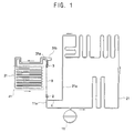
- Figure 1 is a schematic view of a first refrigerant circulatory system according to the present invention;
- Figure 2 is an exploded view of part of the refrigerant circulatory system of Figure 1;
- Figure 3 is an exploded view of part of a second refrigerant circulatory system according to the present invention; and
- Figure 4 is a schematic view of the refrigerant circulatory system of a known refrigerator.
-
- Referring to Figure 1, the refrigerant circulatory system of a refrigerator comprises a
compressor 11 for compressing the refrigerant, acondenser 21 for condensing the refrigerant from thecompressor 11 into the liquid state, and anevaporator 31 for evaporating the liquefied refrigerant from thecondenser 21 so that it draws heat from the air within astorage space 41. - A
condenser outlet pipe 21a connects thecondenser 21 to theevaporator 31 for conveying hot, high pressure refrigerant from thecondenser 21 to theevaporator 31. Aninlet pipe 31b and anoutlet pipe 31a are provided at theevaporator 31. Theinlet pipe 31b conveys the hot, high pressure liquefied refrigerant into theevaporator 31 and the outlet pipe 21b conveys the cold, low pressure gaseous refrigerant from theevaporator 31 to thecompressor 11. Acapillary tube 4 is connected between thecondenser outlet pipe 21a and theevaporator inlet pipe 31b. Thecapillary tube 4 conveys liquefied refrigerant to theevaporator 31 from thecondenser 21. Aconnection pipe 9 is connected between theevaporator 31 and thecompressor 11. Theconnection pipe 9 conveys gaseous refrigerant to thecompressor 11 from theevaporator 31. - A
first coupling member 2 is provided at one end of the connectingpipe 9 and couples it to theinlet pipe 11a of thecompressor 11. Asecond coupling member 3 is provided at the other end of the connectingpipe 9 and couples it to theoutlet pipe 31a of theevaporator 31. - The
capillary tube 4 extends along the inside of the connectingpipe 9 and emerges at either end through respectively the first andsecond coupling members - Referring to Figure 2, the
first coupling member 2 comprises aninline element 5 having first and second open, internally threadedends inline element 5. The branch element 7 has anopen end 7a and a closedend 7b. Anopening 6 provides communication between theinline element 5 and the branch element 7. - The
second coupling member 3 has the same configuration as thefirst coupling member 2. - The end of the
connection pipe 9 are externally threaded and are screwed respectively intosecond ends 5b of the first andsecond coupling members - The
first end 5a of thefirst coupling member 2 has thecompressor inlet pipe 11a screwed into it. Thefirst end 5a of thesecond coupling member 3 has theevaporator outlet pipe 31a screwed into it. - The condenser end of the
capillary tube 4 extends through theopen end 7a of the branch element 7 of thefirst coupling member 2, through theopening 6 and then through thesecond end 5b of theinline element 5 into the connectingpipe 9. At the other end of the connectingpipe 9, thecapillary tube 4 passes through thesecond end 5b of the second coupling member'sinline element 5, through itsopening 6 and out through theopen end 7a of its branch element 7. After emerging from thesecond coupling member 3, thecapillary tube 4 is connected to theevaporator inlet pipe 31b. - The
open ends 7a of the branch elements 7 are sealed with packing 8 to prevent leakage of refrigerant flowing through the connectingpipe 9. - Referring to Figure 3, in a second embodiment, the
first coupling member 52 comprises aninline element 5 having first and second open, internally threadedends inline element 5. The branch element 7 has anopen end 7a. Anopening 6 provides communication between theinline element 5 and the branch element 7. - The
second coupling member 53 has the same configuration as thefirst coupling member 52. - The end of the
connection pipe 9 are externally threaded and are screwed respectively intosecond ends 5b of the first andsecond coupling members - The
first end 5a of thefirst coupling member 52 has thecompressor inlet pipe 11a screwed into it. Thefirst end 5a of thesecond coupling member 53 has theevaporator outlet pipe 31a screwed into it. - The condenser end of the
capillary tube 4 extends through theopen end 7a of the branch element 7 of thefirst coupling member 52, through theopening 6 and then through thesecond end 5b of theinline element 5 into the connectingpipe 9. At the other end of the connectingpipe 9, thecapillary tube 4 passes through thesecond end 5b of the second coupling member'sinline element 5, through itsopening 6 and out through theopen end 7a of its branch element 7. After emerging from thesecond coupling member 53, thecapillary tube 4 is connected to theevaporator inlet pipe 31b. - The
open ends 7a of the branch elements 7 are sealed with packing 8 to prevent leakage of refrigerant flowing through the connectingpipe 9. - With the configurations described above, hot, high pressure gaseous refrigerant from the
compressor 11 is liquefied by thecondenser 21 and the liquefied refrigerant is supplied to theevaporator 31 through thecapillary tube 4. The gaseous refrigerant evaporated in theevaporator 31 draws heat from thestorage space 41 and then passes through thesecond coupling member connection pipe 9 and thefirst coupling member - The liquid refrigerant in the gaseous refrigerant within the
connection pipe 9 is evaporated by heat from thecapillary tube 4 which is inside theconnection pipe 9. - As described above, according to the present invention, there is provided a refrigerator wherein the liquid refrigerant in the gaseous refrigerant flowing into the compressor from the evaporator can be effectively removed, without soldering of the capillary tube and the connection pipe.
Claims (17)
- A heat pump comprising an evaporator (31), a compressor (11), a condenser (21), a refrigerant conduit (9) connecting the evaporator (31) and the compressor (11), and a refrigerant capillary tube (4) connecting the condenser (21) and the evaporator (31) and extending within said conduit (9), characterised by first and second branching members (2, 3; 52, 53) coupled to respective ends of the conduit (9), each branching member (2, 3; 52, 53) having an inline element (5) for conveying refrigerant flowing from the evaporator (31) and a branch element (7) through which the capillary tube (4) extends, wherein the capillary tube (4) extends into the conduit (9) via one branching member (2; 52) and out of the conduit (9) via the other branching member (3; 53).
- A heat pump according to claim 1, wherein the branch element (7) of the first branching member (2) lies parallel to the inline element (5) of the first branching member (2).
- A heat pump according to claim 1 or 2, wherein the branch element (7) of the second branching member (3) lies parallel to the inline element (5) of the second branching member (3).
- A heat pump according to claim 1, wherein the branch element (7) of the first branching member (2) projects substantially perpendicularly from the inline element (5) of the first branching member (2).
- A heat pump according to claim 1 or 4, wherein the branch element (7) of the second branching member (3) projects substantially perpendicularly from the inline element (5) of the second branching member (3).
- A heat pump according to any preceding claim, wherein the inline element (5) of one or both of the branching elements is internally threaded at both ends.
- A heat pump according to any preceding claim, wherein the or each inline element is a substantially straight tube.
- A heat pump according to any preceding claim, including packing material forming a seal between the capillary tube (4) and one or both of the branch elements (7).
- A refrigerator including a heat pump according to any preceding claim.
- A refrigerator comprising:a compressor;a condenser for condensing a refrigerant from the compressor into a liquid state;an evaporator for evaporating the liquid refrigerant into a gaseous state through a heat exchange with an air within a storage;a capillary tube positioned between the evaporator and the condenser;a connection pipe positioned between the evaporator and the connection pipe; andcoupling members positioned between the evaporator and the connection pipe and positioned between the connection pipe and the compressor, for directing the capillary tube to the inside of the connection pipe.
- The refrigerator according to claim 10, wherein each of the coupling members comprises a first coupling element functioning as a passage for the refrigerant, a second coupling element functioning as a passage for the capillary tube, and a connecting element for connecting the first coupling element and the second coupling element.
- The refrigerator according to claim 11, wherein the first and second coupling elements of the coupling member are disposed in parallel with each other.
- The refrigerator according to claim 12, wherein the first coupling element has a first end screw-coupled together with an inlet of the compressor or an outlet of the evaporator and a second end screw-coupled with the connection pipe.
- The refrigerator according to claim 13, wherein the second coupling element has an open end sealingly coupled to the capillary tube and a closed end.
- The refrigerator according to claim 11, wherein the first and second coupling elements of the coupling member are of a T-shape.
- The refrigerator according to claim 15, wherein the first coupling element has a first end screw-coupled together with an inlet of the compressor or an outlet of the evaporator and a second end screw-coupled with the connection pipe.
- The refrigerator according to claim 16, wherein the second coupling element has an open end sealingly coupled to the capillary tube.
Applications Claiming Priority (3)
| Application Number | Priority Date | Filing Date | Title |
|---|---|---|---|
| KR2000008227 | 2000-02-21 | ||
| KR1020000008227A KR100568244B1 (en) | 2000-02-21 | 2000-02-21 | Refrigerator |
| KR0008227 | 2000-02-21 |
Publications (2)
| Publication Number | Publication Date |
|---|---|
| EP1128137A1 true EP1128137A1 (en) | 2001-08-29 |
| EP1128137B1 EP1128137B1 (en) | 2004-09-22 |
Family
ID=19648345
Family Applications (1)
| Application Number | Title | Priority Date | Filing Date |
|---|---|---|---|
| EP00308574A Expired - Lifetime EP1128137B1 (en) | 2000-02-21 | 2000-09-29 | Heat pump |
Country Status (5)
| Country | Link |
|---|---|
| US (1) | US6305188B1 (en) |
| EP (1) | EP1128137B1 (en) |
| JP (1) | JP2001235256A (en) |
| KR (1) | KR100568244B1 (en) |
| DE (1) | DE60014023T2 (en) |
Cited By (2)
| Publication number | Priority date | Publication date | Assignee | Title |
|---|---|---|---|---|
| FR2836542A1 (en) * | 2002-02-26 | 2003-08-29 | Valeo Climatisation | Expansion device for air conditioning loop in motor vehicle, uses capillary expansion unit to lower pressure of fluid emerging from condenser to improve transition from fluid to gaseous state |
| CN104949432A (en) * | 2015-06-15 | 2015-09-30 | 合肥华凌股份有限公司 | Evaporator for refrigerator and refrigerator with same |
Families Citing this family (12)
| Publication number | Priority date | Publication date | Assignee | Title |
|---|---|---|---|---|
| US6973483B2 (en) * | 2000-09-30 | 2005-12-06 | Microsoft Corporation | System and method for using dynamic web components to automatically customize web pages |
| US7243499B2 (en) | 2004-08-16 | 2007-07-17 | Parker Hannifin Corporation | Refrigeration capillary tube inside suction line assembly |
| GB2418478A (en) * | 2004-09-24 | 2006-03-29 | Ti Group Automotive Sys Ltd | A heat exchanger |
| JP4387974B2 (en) * | 2005-04-25 | 2009-12-24 | パナソニック株式会社 | Refrigeration cycle equipment |
| JP4910567B2 (en) * | 2006-08-24 | 2012-04-04 | 株式会社デンソー | Ejector refrigeration cycle |
| US8408022B2 (en) * | 2009-03-25 | 2013-04-02 | Harold E. Stockton, JR. | Hybrid cascade vapor compression refrigeration system |
| CN103000259B (en) * | 2011-09-13 | 2016-03-23 | 辽宁省电力有限公司本溪供电公司 | High voltage power transmission and transforming is with lengthening conducting rod |
| CN105579789B (en) * | 2013-09-27 | 2017-03-01 | 松下健康医疗控股株式会社 | freezer |
| CN103851853A (en) * | 2014-03-28 | 2014-06-11 | 合肥华凌股份有限公司 | Heat exchanger and refrigerator using same |
| DE102017110706A1 (en) * | 2017-05-17 | 2018-11-22 | Miele & Cie. Kg | Throttle device for a heat pump and heat pump with a throttle device |
| EP4343231A4 (en) * | 2021-11-19 | 2024-12-18 | Samsung Electronics Co., Ltd. | AIR CONDITIONING |
| KR102602775B1 (en) * | 2022-07-06 | 2023-11-16 | 동성공조 주식회사 | Capillary self-supercooling maintenance device for battery-powered low-power air conditioners for vehicles |
Citations (8)
| Publication number | Priority date | Publication date | Assignee | Title |
|---|---|---|---|---|
| US2776552A (en) * | 1954-11-08 | 1957-01-08 | Reynolds Metals Co | Sheathed capillary inlet for refrigerator |
| US2959027A (en) * | 1958-11-28 | 1960-11-08 | James O Ewing | Combination evaporator-condenser assembly with concentric tubular construction |
| FR1516944A (en) * | 1967-01-20 | 1968-02-05 | Siemens Elektrogeraete Gmbh | Compressor refrigeration machine incorporated in a plastic foam insulation refrigerator |
| GB1130038A (en) * | 1965-12-16 | 1968-10-09 | R & G Schmoele Metallwerke K G | Refrigerating equipment for refrigerator cabinets or the like |
| DE1807516A1 (en) * | 1968-11-07 | 1970-06-04 | Ver Deutsche Metallwerke Ag | Connection piece for throttle devices |
| US4147037A (en) * | 1976-10-27 | 1979-04-03 | General Electric Company | High efficiency heat exchange for refrigeration suction line/capillary tube assembly |
| EP0209418A1 (en) * | 1985-06-11 | 1987-01-21 | Societe D'electromenager Du Nord Selnor | Method for introducing a capillary tube at any position into a tube having a larger diameter, and device for carrying out this method |
| WO1997027417A1 (en) * | 1996-01-24 | 1997-07-31 | Hage Fittings Gmbh & Co. Kg | Pipe connecting device |
Family Cites Families (6)
| Publication number | Priority date | Publication date | Assignee | Title |
|---|---|---|---|---|
| US2530648A (en) * | 1946-09-26 | 1950-11-21 | Harry Alter Company | Combination accumulator, heat exchanger, and metering device for refrigerating systems |
| US2785542A (en) * | 1954-12-27 | 1957-03-19 | Reynolds Metals Co | Capillary coupled heat exchangers |
| US3145545A (en) * | 1962-10-10 | 1964-08-25 | Wilbert J Jaeger | Air conditioning and refrigeration apparatus for motor vehicles |
| US3566615A (en) * | 1969-04-03 | 1971-03-02 | Whirlpool Co | Heat exchanger with rolled-in capillary for refrigeration apparatus |
| US5819548A (en) * | 1996-11-01 | 1998-10-13 | Clawson; Lawrence G. | Thermal expansion valve and system including such device and method for making such device |
| US5797277A (en) * | 1997-11-06 | 1998-08-25 | Chrysler Corporation | Condensate cooler for increasing refrigerant density |
-
2000
- 2000-02-21 KR KR1020000008227A patent/KR100568244B1/en not_active Expired - Fee Related
- 2000-09-29 EP EP00308574A patent/EP1128137B1/en not_active Expired - Lifetime
- 2000-09-29 DE DE60014023T patent/DE60014023T2/en not_active Expired - Fee Related
- 2000-10-11 US US09/685,611 patent/US6305188B1/en not_active Expired - Fee Related
- 2000-10-17 JP JP2000317131A patent/JP2001235256A/en active Pending
Patent Citations (8)
| Publication number | Priority date | Publication date | Assignee | Title |
|---|---|---|---|---|
| US2776552A (en) * | 1954-11-08 | 1957-01-08 | Reynolds Metals Co | Sheathed capillary inlet for refrigerator |
| US2959027A (en) * | 1958-11-28 | 1960-11-08 | James O Ewing | Combination evaporator-condenser assembly with concentric tubular construction |
| GB1130038A (en) * | 1965-12-16 | 1968-10-09 | R & G Schmoele Metallwerke K G | Refrigerating equipment for refrigerator cabinets or the like |
| FR1516944A (en) * | 1967-01-20 | 1968-02-05 | Siemens Elektrogeraete Gmbh | Compressor refrigeration machine incorporated in a plastic foam insulation refrigerator |
| DE1807516A1 (en) * | 1968-11-07 | 1970-06-04 | Ver Deutsche Metallwerke Ag | Connection piece for throttle devices |
| US4147037A (en) * | 1976-10-27 | 1979-04-03 | General Electric Company | High efficiency heat exchange for refrigeration suction line/capillary tube assembly |
| EP0209418A1 (en) * | 1985-06-11 | 1987-01-21 | Societe D'electromenager Du Nord Selnor | Method for introducing a capillary tube at any position into a tube having a larger diameter, and device for carrying out this method |
| WO1997027417A1 (en) * | 1996-01-24 | 1997-07-31 | Hage Fittings Gmbh & Co. Kg | Pipe connecting device |
Cited By (2)
| Publication number | Priority date | Publication date | Assignee | Title |
|---|---|---|---|---|
| FR2836542A1 (en) * | 2002-02-26 | 2003-08-29 | Valeo Climatisation | Expansion device for air conditioning loop in motor vehicle, uses capillary expansion unit to lower pressure of fluid emerging from condenser to improve transition from fluid to gaseous state |
| CN104949432A (en) * | 2015-06-15 | 2015-09-30 | 合肥华凌股份有限公司 | Evaporator for refrigerator and refrigerator with same |
Also Published As
| Publication number | Publication date |
|---|---|
| US6305188B1 (en) | 2001-10-23 |
| EP1128137B1 (en) | 2004-09-22 |
| KR20010083721A (en) | 2001-09-01 |
| DE60014023T2 (en) | 2006-02-23 |
| JP2001235256A (en) | 2001-08-31 |
| DE60014023D1 (en) | 2004-10-28 |
| KR100568244B1 (en) | 2006-04-05 |
Similar Documents
| Publication | Publication Date | Title |
|---|---|---|
| EP1128137B1 (en) | Heat pump | |
| US6681597B1 (en) | Integrated suction line heat exchanger and accumulator | |
| US6536231B2 (en) | Tube and shell heat exchanger for multiple circuit refrigerant system | |
| CA1099934A (en) | Heat pump system | |
| US6386277B1 (en) | Heat exchanger header construction | |
| IL144148A0 (en) | Vapor compression system and method | |
| ITTO981041A1 (en) | MULTI-UNIT AIR CONDITIONER WITH A BYPASS SECTION TO ADJUST THE REFRIGERANT FLOW. | |
| JP3617083B2 (en) | Receiver integrated refrigerant condenser | |
| JP2827404B2 (en) | Refrigerant condenser | |
| US6467302B1 (en) | Accumulator for a refrigeration system | |
| US6708519B1 (en) | Accumulator with internal desiccant | |
| US20080034787A1 (en) | Refrigerant circuit system | |
| JP2005114283A (en) | Vehicular air conditioner | |
| CN118009591A (en) | Economizer integrated module | |
| EP0039390A2 (en) | Dehydrating and filtering unit for a refrigerant circuit | |
| KR100220725B1 (en) | Refrigerant Distribution Structure of Condenser for Air Conditioner | |
| JP2004045012A (en) | Refrigeration cycle equipment condenser | |
| CN218972923U (en) | Refrigerating system, muffler assembly, evaporator assembly and refrigerating equipment | |
| JP4027931B2 (en) | Air conditioner | |
| JP2923151B2 (en) | Refrigeration cycle | |
| KR19990034725A (en) | Refrigerant equalization branch of refrigeration cycle | |
| JPH0322700Y2 (en) | ||
| KR100286297B1 (en) | Air conditioner for driving multiple indoor units | |
| JPH0476335A (en) | Cooling device and cooling/heating device | |
| JPH0486433A (en) | Cooling device and cooling/heating device |
Legal Events
| Date | Code | Title | Description |
|---|---|---|---|
| PUAI | Public reference made under article 153(3) epc to a published international application that has entered the european phase |
Free format text: ORIGINAL CODE: 0009012 |
|
| AK | Designated contracting states |
Kind code of ref document: A1 Designated state(s): AT BE CH CY DE DK ES FI FR GB GR IE IT LI LU MC NL PT SE Kind code of ref document: A1 Designated state(s): DE FR GB |
|
| AX | Request for extension of the european patent |
Free format text: AL;LT;LV;MK;RO;SI |
|
| 17P | Request for examination filed |
Effective date: 20011220 |
|
| AKX | Designation fees paid |
Free format text: DE FR GB |
|
| 17Q | First examination report despatched |
Effective date: 20031009 |
|
| GRAP | Despatch of communication of intention to grant a patent |
Free format text: ORIGINAL CODE: EPIDOSNIGR1 |
|
| GRAS | Grant fee paid |
Free format text: ORIGINAL CODE: EPIDOSNIGR3 |
|
| GRAA | (expected) grant |
Free format text: ORIGINAL CODE: 0009210 |
|
| AK | Designated contracting states |
Kind code of ref document: B1 Designated state(s): DE FR GB |
|
| REG | Reference to a national code |
Ref country code: GB Ref legal event code: FG4D |
|
| RAP2 | Party data changed (patent owner data changed or rights of a patent transferred) |
Owner name: SAMSUNG ELECTRONICS CO., LTD. |
|
| REF | Corresponds to: |
Ref document number: 60014023 Country of ref document: DE Date of ref document: 20041028 Kind code of ref document: P |
|
| PLBE | No opposition filed within time limit |
Free format text: ORIGINAL CODE: 0009261 |
|
| STAA | Information on the status of an ep patent application or granted ep patent |
Free format text: STATUS: NO OPPOSITION FILED WITHIN TIME LIMIT |
|
| ET | Fr: translation filed | ||
| 26N | No opposition filed |
Effective date: 20050623 |
|
| PGFP | Annual fee paid to national office [announced via postgrant information from national office to epo] |
Ref country code: FR Payment date: 20080915 Year of fee payment: 9 |
|
| PGFP | Annual fee paid to national office [announced via postgrant information from national office to epo] |
Ref country code: DE Payment date: 20081002 Year of fee payment: 9 |
|
| PGFP | Annual fee paid to national office [announced via postgrant information from national office to epo] |
Ref country code: GB Payment date: 20081001 Year of fee payment: 9 |
|
| GBPC | Gb: european patent ceased through non-payment of renewal fee |
Effective date: 20090929 |
|
| REG | Reference to a national code |
Ref country code: FR Ref legal event code: ST Effective date: 20100531 |
|
| PG25 | Lapsed in a contracting state [announced via postgrant information from national office to epo] |
Ref country code: FR Free format text: LAPSE BECAUSE OF NON-PAYMENT OF DUE FEES Effective date: 20090930 Ref country code: DE Free format text: LAPSE BECAUSE OF NON-PAYMENT OF DUE FEES Effective date: 20100401 |
|
| PG25 | Lapsed in a contracting state [announced via postgrant information from national office to epo] |
Ref country code: GB Free format text: LAPSE BECAUSE OF NON-PAYMENT OF DUE FEES Effective date: 20090929 |