EP1128085A2 - Spring baseplate - Google Patents
Spring baseplate Download PDFInfo
- Publication number
- EP1128085A2 EP1128085A2 EP01102132A EP01102132A EP1128085A2 EP 1128085 A2 EP1128085 A2 EP 1128085A2 EP 01102132 A EP01102132 A EP 01102132A EP 01102132 A EP01102132 A EP 01102132A EP 1128085 A2 EP1128085 A2 EP 1128085A2
- Authority
- EP
- European Patent Office
- Prior art keywords
- spring
- section
- base element
- intermediate plate
- plate
- Prior art date
- Legal status (The legal status is an assumption and is not a legal conclusion. Google has not performed a legal analysis and makes no representation as to the accuracy of the status listed.)
- Granted
Links
Images


Classifications
-
- F—MECHANICAL ENGINEERING; LIGHTING; HEATING; WEAPONS; BLASTING
- F16—ENGINEERING ELEMENTS AND UNITS; GENERAL MEASURES FOR PRODUCING AND MAINTAINING EFFECTIVE FUNCTIONING OF MACHINES OR INSTALLATIONS; THERMAL INSULATION IN GENERAL
- F16F—SPRINGS; SHOCK-ABSORBERS; MEANS FOR DAMPING VIBRATION
- F16F1/00—Springs
- F16F1/02—Springs made of steel or other material having low internal friction; Wound, torsion, leaf, cup, ring or the like springs, the material of the spring not being relevant
- F16F1/04—Wound springs
- F16F1/12—Attachments or mountings
- F16F1/126—Attachments or mountings comprising an element between the end coil of the spring and the support proper, e.g. an elastomeric annulus
Definitions
- the invention relates to a spring pad for arrangement between a spring plate and a helical spring.
- Such spring pads are used, for example, in vehicle construction Spring damper assemblies used for suspension of the vehicle wheels. However, it is Use not limited to vehicle construction. Rather, feather pads Use wherever helical springs are supported against a spring plate Need to become.
- the spring plate can be used separately with the spring Be part, but also integral with a wall portion of a larger unit, for. B. the vehicle body against which the spring is supported.
- Spring pads made of elastomer material are generally known from the prior art.
- DE 196 32 184 A1 discloses an elastic pad made of several layers of a film material is produced. This will be between the last one Coil of a spring and the associated spring plate arranged.
- Another, Spring support consisting exclusively of elastomer material is from DE 196 09 250 A1 known as a ring-like disc for supporting a barrel-shaped coil spring is trained.
- a spring strut is known from DE 42 11 176 C2, in which the spring support against a spring plate via a solid rubber ring.
- a spacer made of metal arranged its thickness increases from one side to the other, so that the solid rubber ring against the Spring plate is supported at an angle. This allows a uniform elasticity of the Achieve spring support, which counteracts bulging. The constructive However, the effort is considerable.
- EP 0 924 445 A2 discloses a metal reinforcement element in embed a rubber body so that it is enclosed by the rubber. For Simplification of production is proposed in EP 0 924 445 A2 instead of Reinforcing element made of metal to use one made of plastic.
- a support could directly against the usually metallic spring plate in Be considered.
- the direct contact between a metal spring and a metallic spring plate is however under dynamic loading of the spring like it occurs, for example, in a wheel suspension when operating a motor vehicle in which Usually associated with unpleasant squeaking and creaking noises.
- the invention has for its object a noise-free under load To create spring pad or spring arrangement.
- a spring pad for arrangement between a spring plate and a helical spring comprising a Base element made of an elastomer material for support against the spring plate, and an intermediate plate, preferably made of metal, on the side facing the spring of the Arranged base element, wherein the intermediate plate has a contact section, against the winding sections of the spring to the system, at least in the event of greater compression come, and the contact section has openings through which the Extend projections provided through the base element, which protrude into the contact section Protrude towards the spring.
- the intermediate plate which is preferably made of metal, also results in a certain broadening of the application of force into the elastomer material Base element. Depending on the thickness of the metal plate, a softer one may be used Elastomer or a thinner base element can be used.
- the intermediate plate is preferably made from a sacrificial anode material, for example zinc, manufactured and then serves to protect the spring from corrosion.
- the contact section is annular educated. Furthermore, the openings in the intermediate plate are directed radially Longitudinal slots are provided on the annular contact section.
- the annular coil springs used can be used independently of Deflection state to achieve a good suppression of noise.
- the projections are preferably each of the circumferential shape associated opening designed accordingly.
- the openings restrict the deformation space of the projections when compressed. This results in a certain structural stiffening effect in the area of the projections, which is something are harder than a freely deformable section of the same material on the base element. Even when using a relatively soft elastomer, it can be a good one Suppression of noise can be guaranteed.
- the intermediate plate is preferably attached to the base element by Vulcanizing or gluing.
- the protrusion by which the projections protrude beyond the contact section is preferably 0.75 to 1.25 mm. In this area it can be ensured that the Winding sections of the spring ultimately bear against the stiffer intermediate plate come to achieve a good introduction of force into the base element, on the other hand the formation of squeaking and creaking noises is particularly reliably prevented.
- the intermediate plate as Ring disc is formed, the thickness of about 5 to 10 percent of the thickness of a underlying flange portion of the base member.
- the washer can be also easy to manufacture from sheet metal.
- the Invention on the base element an annular centering section for radial contact provided against an outgoing turn section at the end of the spring.
- the Centering section is formed, for example, in one piece with the base element. He can but also as a separate component or section of the spring plate in the direction of the spring protruding to be coupled to the base element.
- a recess Picking up and supporting an outgoing turn section at the end of the spring intended For the use of coil springs with non-flattened ends, another advantageous embodiment of the invention on the base element a recess Picking up and supporting an outgoing turn section at the end of the spring intended.
- the helical spring is initially soft and without in the normal state Interposition of a metal part supported against the spring plate. With a larger one Resilience then reach further turn sections against the intermediate plate Investment. This allows, above all, a progressive spring characteristic with simple Realize means.
- the intermediate plate with the contact section extends to the annular centering section, with a spring end against the in the installed state Intermediate plate comes to rest.
- a recess adapted to the spring end on the Base element is then not required. Its shape therefore remains simple and for different springs can be used.
- a spring arrangement comprising a helical spring, which is arranged between two spring plates, wherein at least between one of the spring plates and the spring a spring pad of the is arranged as described above.
- the helical spring is barrel-shaped and with smaller coil diameters at the ends of the spring educated.
- Outgoing turn sections at the ends of the spring are each in one Recess supported on the base elements of the spring pads, however, come Winding sections with a larger winding diameter, at least with a larger one Deflection against the respective contact section of the intermediate plate and there located projections of the base element to the system.
- a spring arrangement is shown, for example, in a wheel or Axle suspension of a motor vehicle can be installed. It will be there between two Spring plates, which are not shown in Figure 10, held, an upper Spring plate on the body side and a lower spring plate on the wheel side.
- the upper Spring plate can be integrally formed with part of the vehicle body.
- the spring arrangement shown comprises a coil spring 1, which is between two Spring pads 2 and 3 are incorporated and can be supported against the spring plate.
- the coil spring 1 here is a steel spring with a barrel-shaped outer contour Application whose winding diameter decreases towards the axial ends of the spring.
- the spring ends 4 and 5 are not created here and are shaped accordingly Recesses on the spring pads 2 and 3 added.
- a conventional cylinder coil spring to use.
- the spring ends can also be placed on the last turn and, if necessary, be ground flat so that the ends of the spring are flat against the spring pads.
- the spring pads 2 and 3 shown in FIG. 10 are the first exemplary embodiment in FIG Figures 1 to 4 and as a second embodiment in Figures 5 to 7 in detail shown and are explained in more detail below.
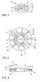
- FIGS. 1 to 4 show the upper spring base 2 from FIG. 10
- Spring pad 2 comprises an annular base element 6 made of an elastomer material and an intermediate plate 7 made of metal, e.g. Steel on the side facing the spring 1 is arranged.
- the base element 6 is designed as a substantially flat disc and has an annular flange portion 8, which is radially centered around a arranged centering section 9 extends.
- the annular flange section 8 has one essentially constant thickness. From this, the centering section 9 lifts in the direction the spring 1. It is mainly used for the radial definition of the last turns of the spring 1 on the spring pad 2 and has several, preferably three, on its outer edge 10 claw-like projections 11 which hook with a winding section of the spring 1 or latch.
- the base element 6 further comprises a central through opening 12, through which, for example, a section of a damper, not shown here can be.
- a plurality of projections 13 are provided, each in the form of elongated ribs Extend radial direction.
- the projections 13 are preferably uniform over the circumference the flange section 8 distributed.
- the Intermediate plate 7 largely from the flange section 8 on the spring side. Indeed openings 14 corresponding to the projections 13 are formed in the intermediate plate 7, through which the projections 13 extend through a spring-side contact surface 15 of the intermediate plate 7 to protrude slightly.
- the protrusion of the protrusions 13 is 0.75 to 1.25 mm.
- the intermediate plate 7 is, as can be seen in particular in FIG. 4, as thin-walled, annular sheet metal disc of constant thickness.
- the is Thickness of the sheet metal disc is only about 5 to 10 percent of the thickness of the underlying Flange section 8 of the base element 6.
- the openings 14 extend in the essentially over the entire ring width of the contact surface 15, against which at a Compression, especially with a stronger compression of the spring with 1 turn sections larger turn diameter come to the plant.
- a barrel-shaped Coil spring 1 as shown in Figure 10 can temporarily at higher loads several turns come into abutment against the contact surface 15, that swing freely with smaller spring travel. This allows one with increasing Spring curve becoming stiffer spring characteristic, d. H. a progressive characteristic curve realize.
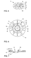
- FIGS. 5 to 7 Another exemplary embodiment of a spring pad is shown in FIGS. 5 to 7, which represents the spring support 3 on the wheel side lying at the bottom in FIG.
- the Spring pad 3 again includes a base element 6 from a Elastomer material for support against a spring plate. Furthermore, the Spring pad 3 is a metallic intermediate plate 7, which points to the spring 1 Side of the base element 6 is arranged.
- the base element 6 and the intermediate plate 7 are essentially as in the first Embodiment designed, so that only the differences in the following is briefly discussed.
- For similar elements in Figures 1 to 4 and in Figures 5 to 7 use the same reference numerals.
- the base element 6 is formed without claw-like projections 11.
- An expiring Winding section of the spring 1 is by the centering section 9 on the Spring pad in a shape adapted to the outgoing winding section 4 Recess 5 held.
- the Flange section 8 of the base element 6 executed with a smaller wall thickness, so that in the area of the recess 5 on the side facing away from the spring 1 protruding wall area 18 results, which closes the recess 5 on the back.
- the Wall section 18 can, for example, be used for centering purposes Spring plates can be used.
- a support projection 19 is located on a radial outer wall of the centering section 9 formed, which is adjacent to the deepest point of the recess 5.
- This support projection 19th serves the radial and axial support of a winding section of the spring 1.
- the spring pad 20 of the third embodiment comprises a base element 21 made of an elastomer material for support against a spring plate, not shown, and an intermediate plate 22, which is arranged on the spring side of the base element 21.
- the intermediate plate 22 is a sacrificial anode for the spring is also preferred here.
- the base element 21 is essentially formed by an annular flange 23 constant wall thickness formed in the middle of a projecting on the spring side Centering section in the form of a collar 24 with a through opening 25.
- a radial projection 26 is provided below centered on an outgoing turn portion of a spring to the spring base 20 and can be axially secured to it.
- the annular flange 23 has on its spring side projections 27 which are elongated Ribs are aligned in the radial direction and through openings 28 of the intermediate plate 22 extend through to project beyond their contact surface 29 for turns of the spring.
- the projections 27 and openings 28 can be as in the two previously described Embodiments are dimensioned, the ring width of the contact surface 29 in Depends on the springs used.
- the spring pad 20 shown in the third embodiment is particularly suitable for springs with a flat end, where for example, the outgoing turn is applied to a previous turn and that If necessary, the end is additionally ground flat.
Landscapes
- Engineering & Computer Science (AREA)
- General Engineering & Computer Science (AREA)
- Mechanical Engineering (AREA)
- Springs (AREA)
- Pens And Brushes (AREA)
- Polishing Bodies And Polishing Tools (AREA)
- Lead Frames For Integrated Circuits (AREA)
- Braking Arrangements (AREA)
- Vehicle Step Arrangements And Article Storage (AREA)
Abstract
Description
Die Erfindung betrifft eine Federunterlage zur Anordnung zwischen einem Federteller und einer schraubenförmigen Feder.The invention relates to a spring pad for arrangement between a spring plate and a helical spring.
Derartige Federunterlagen werden beispielsweise im Fahrzeugbau in Federdämpferanordnungen zur Aufhängung der Fahrzeugräder verwendet. Allerdings ist die Verwendung nicht auf den Fahrzeugbau beschränkt. Vielmehr lassen sich Federunterlagen überall dort einsetzen, wo schraubenförmige Federn gegen einen Federteller abgestützt werden müssen. Der Federteller kann hierbei ein separat mit der Feder zu verwendendes Bauteil sein, jedoch auch integral mit einem Wandabschnitt einer größeren Einheit, z. B. dem Fahrzeugaufbau ausgebildet werden, gegen den sich die Feder abstützt.Such spring pads are used, for example, in vehicle construction Spring damper assemblies used for suspension of the vehicle wheels. However, it is Use not limited to vehicle construction. Rather, feather pads Use wherever helical springs are supported against a spring plate Need to become. The spring plate can be used separately with the spring Be part, but also integral with a wall portion of a larger unit, for. B. the vehicle body against which the spring is supported.
Federunterlagen aus Elastomermaterial sind aus dem Stand der Technik generell bekannt. So offenbart beispielsweise die DE 196 32 184 A1 eine elastische Auflage, die aus mehreren Schichten eines Folienmaterials hergestellt ist. Diese wird zwischen der letzten Windung einer Feder und dem zugehörigen Federteller angeordnet. Eine weitere, ausschließlich aus Elastomermaterial bestehende Federunterlage ist aus der DE 196 09 250 A1 bekannt, die als ringartige Scheibe zur Abstützung einer tonnenförmigen Schraubenfeder ausgebildet ist.Spring pads made of elastomer material are generally known from the prior art. For example, DE 196 32 184 A1 discloses an elastic pad made of several layers of a film material is produced. This will be between the last one Coil of a spring and the associated spring plate arranged. Another, Spring support consisting exclusively of elastomer material is from DE 196 09 250 A1 known as a ring-like disc for supporting a barrel-shaped coil spring is trained.
Weiterhin ist aus der DE 42 11 176 C2 ein Federbein bekannt, bei dem die Federabstützung gegen einen Federteller über einen massiven Vollgummiring erfolgt. Zur Vermeidung des Ausbeulens einer Schraubenfeder mit nicht-angelegten Federenden ist zwischen dem Federteller und dem Vollgummiring eine Distanzscheibe aus Metall angeordnet, deren Dicke von der einen Seite zu der anderen Seite zunimmt, so daß der Vollgummiring gegen den Federteller schräg abgestützt ist. Hierdurch läßt sich eine gleichmäßige Elastizität der Federabstützung erzielen, womit einem Ausbeulen entgegengewirkt wird. Der konstruktive Aufwand ist jedoch beträchtlich. Furthermore, a spring strut is known from DE 42 11 176 C2, in which the spring support against a spring plate via a solid rubber ring. To avoid the Bulge of a coil spring with spring ends not applied is between the Spring plate and the solid rubber ring a spacer made of metal arranged, its thickness increases from one side to the other, so that the solid rubber ring against the Spring plate is supported at an angle. This allows a uniform elasticity of the Achieve spring support, which counteracts bulging. The constructive However, the effort is considerable.
Schließlich ist aus der EP 0 924 445 A2 bekannt, ein Verstärkungselement aus Metall in
einen Gummikörper einzubetten, so daß dieses vom Gummi umschlossen ist. Zur
Vereinfachung der Herstellung wird in der EP 0 924 445 A2 vorgeschlagen, anstelle des
Verstärkungselementes aus Metall eines aus Kunststoff zu verwenden.Finally,
In allen Fällen wird die Federkraft konzentriert im Bereich der aufliegenden Windungsabschnitte der Feder in das Elastomermaterial eingeleitet. Dieses ist folglich entsprechend den maximal auftretenden Kräften und Flächenpressungen unter den aufliegenden Windungsabschnitten zu dimensionieren. Hieraus resultieren sowohl konstruktive Einschränkungen im Hinblick auf die Materialauswahl als auch auf die Formgestaltung.In all cases, the spring force is concentrated in the area of the surface Winding sections of the spring introduced into the elastomer material. This is therefore according to the maximum forces and surface pressures under the dimensioned overlying winding sections. This results in both constructive restrictions with regard to the choice of materials as well as the Shape design.
Zwar könnte eine Abstützung unmittelbar gegen den in der Regel metallischen Federteller in Erwägung gezogen werden. Die unmittelbare Anlage zwischen einer Metallfeder und einem metallischen Federteller ist jedoch bei dynamischer Belastung der Feder, wie sie beispielsweise in einer Radaufhängung beim Betrieb eines Kraftfahrzeuges auftritt, in der Regel mit unangenehmen Quietsch- und Knarzgeräuschen verbunden.A support could directly against the usually metallic spring plate in Be considered. The direct contact between a metal spring and a metallic spring plate is however under dynamic loading of the spring like it occurs, for example, in a wheel suspension when operating a motor vehicle in which Usually associated with unpleasant squeaking and creaking noises.
Der Erfindung liegt die Aufgabe zugrunde, eine unter Belastung geräuschfreie Federunterlage bzw. Federanordnung zu schaffen.The invention has for its object a noise-free under load To create spring pad or spring arrangement.
Die vorstehend genannte Aufgabe wird gelöst durch eine Federunterlage zur Anordnung zwischen einem Federteller und einer schraubenförmigen Feder, umfassend ein Sockelelement aus einem Elastomermaterial zur Abstützung gegen den Federteller, und eine Zwischenplatte, vorzugsweise aus Metall, die an der zu der Feder weisenden Seite des Sockelelementes angeordnet, wobei die Zwischenplatte einen Anlageabschnitt aufweist, gegen den wenigstens bei stärkerem Einfedern Windungsabschnitte der Feder zur Anlage kommen, und der Anlageabschnitt Öffnungen aufweist, durch welche sich an dem Sockelelement vorgesehene Vorsprünge hindurcherstrecken, die den Anlageabschnitt in Richtung auf die Feder überragen.The above object is achieved by a spring pad for arrangement between a spring plate and a helical spring, comprising a Base element made of an elastomer material for support against the spring plate, and an intermediate plate, preferably made of metal, on the side facing the spring of the Arranged base element, wherein the intermediate plate has a contact section, against the winding sections of the spring to the system, at least in the event of greater compression come, and the contact section has openings through which the Extend projections provided through the base element, which protrude into the contact section Protrude towards the spring.
Während des Einfederns der Feder wälzen zumindest bei größeren Federkräften Windungsabschnitte der Feder an der Zwischenplatte ab. Vor einer Anlage gegen die Zwischenplatte werden die über die Zwischenplatte hinausragenden Vorsprünge aus dem Material des Sockelelementes niedergedrückt. Hieraus resultiert eine Verminderung der Geräuschemissionen. Im Anlagezustand werden insbesondere höherfrequente Erregungen mit kleinen Amplituden von den Vorsprüngen geschluckt.During the compression of the spring, roll at least with larger spring forces Winding sections of the spring on the intermediate plate. Before an investment against the Intermediate plate, the protrusions protruding beyond the intermediate plate from the Material of the base element depressed. This results in a reduction in the Noise emissions. Higher-frequency excitations are in particular in the system state swallowed by the projections with small amplitudes.
Durch die vorzugsweise aus Metall bestehende Zwischenplatte ergibt sich auch eine gewisse Verbreiterung der Krafteinleitung in das aus Elastomermaterial bestehende Sockelelement. Je nach Dicke der Metallplatte kann gegebenenfalls ein weicheres Elastomer oder ein dünneres Sockelelement verwendet werden.The intermediate plate, which is preferably made of metal, also results in a certain broadening of the application of force into the elastomer material Base element. Depending on the thickness of the metal plate, a softer one may be used Elastomer or a thinner base element can be used.
Die Zwischenplatte ist bevorzugt aus einem Opferanodenmaterial, beispielsweise Zink, hergestellt und dient dann dem Korrosionsschutz der Feder.The intermediate plate is preferably made from a sacrificial anode material, for example zinc, manufactured and then serves to protect the spring from corrosion.
In einer vorteilhaften Ausgestaltung der Erfindung ist der Anlageabschnitt ringförmig ausgebildet. Weiterhin sind die Öffnungen in der Zwischenplatte als radial gerichtete Längsschlitze an dem ringförmigen Anlageabschnitt vorgesehen. Bei den üblicherweise verwendeten, ringförmigen Schraubenfedern läßt sich damit unabhängig vom Einfederungszustand eine gute Unterdrückung der Geräuschbildung verwirklichen.In an advantageous embodiment of the invention, the contact section is annular educated. Furthermore, the openings in the intermediate plate are directed radially Longitudinal slots are provided on the annular contact section. In the usual The annular coil springs used can be used independently of Deflection state to achieve a good suppression of noise.
Vorzugsweise sind die Vorsprünge in ihrer Umfangsform der Umfangsform der jeweils zugehörigen Öffnung entsprechend ausgebildet. Durch die gleichartige Ausbildung der Vorsprünge und zugehörigen Öffnungen ergibt sich eine klar definierte Lagezuordnung zwischen dem Sockelelement und der Zwischenplatte. Weiterhin schränken die Öffnungen den Verformungsraum der Vorsprünge beim Zusammendrücken ein. Hierdurch ergibt sich eine gewisse strukturelle Versteifungswirkung im Bereich der Vorsprünge, die damit etwas härter sind, als ein frei verformbarer Abschnitt gleichen Materials an dem Sockelelement. Selbst bei der Verwendung eines verhältnismäßig weichen Elastomers kann damit eine gute Unterdrückung der Geräuschbildung gewährleistet werden.In their circumferential shape, the projections are preferably each of the circumferential shape associated opening designed accordingly. By the similar training of Projections and associated openings result in a clearly defined location assignment between the base element and the intermediate plate. Furthermore, the openings restrict the deformation space of the projections when compressed. This results in a certain structural stiffening effect in the area of the projections, which is something are harder than a freely deformable section of the same material on the base element. Even when using a relatively soft elastomer, it can be a good one Suppression of noise can be guaranteed.
Die Befestigung der Zwischenplatte an dem Sockelelement erfolgt vorzugsweise durch Anvulkanisieren oder Ankleben.The intermediate plate is preferably attached to the base element by Vulcanizing or gluing.
Bevorzugt beträgt der Überstand, um den die Vorsprünge den Anlageabschnitt überragen, 0,75 bis 1,25 mm. In diesem Bereich läßt sich sicherstellen, daß beim Einfedern die Windungsabschnitte der Feder letztlich zur Anlage gegen die steifere Zwischenplatte kommen, um eine gute Krafteinleitung in das Sockelelement zu erzielen, andererseits jedoch die Bildung von Quietsch- und Knarzgeräuschen besonders zuverlässig verhindert wird. The protrusion by which the projections protrude beyond the contact section is preferably 0.75 to 1.25 mm. In this area it can be ensured that the Winding sections of the spring ultimately bear against the stiffer intermediate plate come to achieve a good introduction of force into the base element, on the other hand the formation of squeaking and creaking noises is particularly reliably prevented.
Aus Gründen der Gewichtsersparnis ist es vorteilhaft, wenn die Zwischenplatte als Ringscheibe ausgebildet ist, deren Dicke etwa 5 bis 10 Prozent der Dicke eines untergelagerten Flanschabschnittes des Sockelelements beträgt. Die Ringscheibe läßt sich zudem einfach aus Blechmaterial herstellen.For reasons of weight saving, it is advantageous if the intermediate plate as Ring disc is formed, the thickness of about 5 to 10 percent of the thickness of a underlying flange portion of the base member. The washer can be also easy to manufacture from sheet metal.
Zur Vermeidung des Ausbeulens der Feder wird in einer bevorzugten Ausgestaltung der Erfindung an dem Sockelelement ein ringförmiger Zentrierabschnitt zur radialen Anlage gegen einen auslaufenden Windungsabschnitt am Ende der Feder vorgesehen. Der Zentrierabschnitt wird beispielsweise einstückig mit dem Sockelelement ausgebildet. Er kann aber auch als separates Bauteil oder Abschnitt des Federtellers in Richtung der Feder hervorstehend mit dem Sockelelement gekoppelt werden.In order to avoid bulging of the spring, the Invention on the base element an annular centering section for radial contact provided against an outgoing turn section at the end of the spring. The Centering section is formed, for example, in one piece with the base element. He can but also as a separate component or section of the spring plate in the direction of the spring protruding to be coupled to the base element.
In einer weiteren, vorteilhaften Ausgestaltung der Erfindung sind an dem Sockelelement, vorzugsweise an dem Zentrierabschnitt, Verrasteinrichtungen zur Kopplung mit einem auslaufenden Windungsabschnitt am Ende der Feder vorgesehen. Damit kann die Federunterlage bereits vor der Abstützung der Feder an einem Federteller an der Feder gesichert werden und nicht verloren gehen. Dies ist beispielsweise dann vorteilhaft, wenn die Federunterlage in einer vormontierbaren Federdämpferanordnung verwendet wird, die als im wesentlichen vorgefertigte Baueinheit an einem Fahrzeugaufbau anzubringen ist, da der obere Federteller in solchen Fällen oftmals in den Aufbau des Fahrzeugs integriert ist.In a further advantageous embodiment of the invention, on the base element, preferably on the centering section, locking devices for coupling to a outgoing turn section provided at the end of the spring. So that Spring pad already before the spring is supported on a spring plate on the spring secured and not lost. This is advantageous, for example, if the Spring pad is used in a preassembled spring damper assembly, which as in essential prefabricated unit to be attached to a vehicle body, since the upper spring plate is often integrated into the body of the vehicle in such cases.
Zur Verwendung von Schraubenfedern mit nicht abgeflachten Enden wird in einer weiteren, vorteilhaften Ausgestaltung der Erfindung an dem Sockelelement eine Ausnehmung zur Aufnahme und Abstützung eines auslaufenden Windungsabschnittes am Ende der Feder vorgesehen. Damit ist die Schraubefeder im Normalzustand zunächst weich und ohne Zwischenschaltung eines Metallteils gegen den Federteller abgestützt. Bei einer größeren Einfederung gelangen dann weitere Windungsabschnitte gegen die Zwischenplatte zur Anlage. Hierdurch läßt sich vor allem auch eine progressive Federkennlinie mit einfachen Mitteln verwirklichen.For the use of coil springs with non-flattened ends, another advantageous embodiment of the invention on the base element a recess Picking up and supporting an outgoing turn section at the end of the spring intended. The helical spring is initially soft and without in the normal state Interposition of a metal part supported against the spring plate. With a larger one Resilience then reach further turn sections against the intermediate plate Investment. This allows, above all, a progressive spring characteristic with simple Realize means.
In einer alternativen Ausführungsform, die sich besonders für Schraubenfedern mit abgeflachten Enden eignet, und die sich durch eine besonders große Einfachheit der Konstruktion auszeichnet, erstreckt sich die Zwischenplatte mit dem Anlageabschnitt bis an den ringförmigen Zentrierabschnitt, wobei im Einbauzustand ein Federende gegen die Zwischenplatte zur Anlage kommt. Eine an das Federende angepaßte Ausnehmung an dem Sockelelement ist dann nicht erforderlich. Diese bleibt folglich in seiner Form einfach und für unterschiedliche Federn verwendbar.In an alternative embodiment, which is particularly suitable for coil springs flattened ends is suitable, and which is characterized by a particularly great simplicity of the Design distinguishes, the intermediate plate with the contact section extends to the annular centering section, with a spring end against the in the installed state Intermediate plate comes to rest. A recess adapted to the spring end on the Base element is then not required. Its shape therefore remains simple and for different springs can be used.
Die obengenannte Aufgabe wird weiterhin gelöst durch eine Federanordnung, umfassend eine schraubenförmige Feder, die zwischen zwei Federtellern angeordnet ist, wobei mindestens zwischen einem der Federteller und der Feder eine Federunterlage der vorstehend beschriebenen Art angeordnet ist. Damit ergeben sich die bereits oben erläuterten Vorteile. Insbesondere wird eine Federanordnung geschaffen, die das Entstehen von Quietsch- und Knarzgeräuschen verhindert.The above object is further achieved by a spring arrangement comprising a helical spring, which is arranged between two spring plates, wherein at least between one of the spring plates and the spring a spring pad of the is arranged as described above. This results in the above explained advantages. In particular, a spring arrangement is created to prevent the emergence prevented from squeaking and creaking noises.
In einer vorteilhaften Ausgestaltung der Federanordnung ist die schraubenförmige Feder tonnenförmig und mit kleineren Windungsdurchmessern an den Enden der Feder ausgebildet. Auslaufende Windungsabschnitte an den Enden der Feder sind jeweils in einer Ausnehmung an den Sockelelementen der Federunterlagen abgestützt, hingegen kommen Windungsabschnitte mit größerem Windungsdurchmesser wenigstens bei einer stärkeren Einfederung gegen den jeweiligen Anlageabschnitt der Zwischenplatte und die dort befindlichen Vorsprünge des Sockelelements zur Anlage.In an advantageous embodiment of the spring arrangement, the helical spring is barrel-shaped and with smaller coil diameters at the ends of the spring educated. Outgoing turn sections at the ends of the spring are each in one Recess supported on the base elements of the spring pads, however, come Winding sections with a larger winding diameter, at least with a larger one Deflection against the respective contact section of the intermediate plate and there located projections of the base element to the system.
Die Erfindung wird nachfolgend anhand von in der Zeichnung dargestellten Ausführungsbeispielen näher erläutert. Die Zeichnung zeigt in
Figur 1- eine räumliche Ansicht eines ersten Ausführungsbeispiels einer Federunterlage,
Figur 2- eine Ansicht auf die Seite der Federunterlage von
Figur 1, an der eine Feder abgestützt werden kann, Figur 3- einen Schnitt durch die
Federunterlage nach Figur 1 entlang der Linie A-A inFigur 2, Figur 4- eine weitere räumliche Ansicht der Federunterlage nach
den Figuren 1bis 3, bei der ein Sockelelement und eine an dieser vorgesehene Zwischenplatte auseinandergezogen dargestellt sind, Figur 5- eine räumliche Ansicht eines zweiten Ausführungsbeispiels einer Federunterlage,
Figur 6- eine Ansicht auf die Seite der
Federunterlage von Figur 5, an der eine Feder abgestützt werden kann, Figur 7- einen Schnitt durch die
Federunterlage nach Figur 1 entlang der Linie B-B inFigur 6, Figur 8- ein weiteres Ausführungsbeispiel einer Federunterlage in einer Ansicht auf die Seite, an welcher eine Feder abgestützt werden kann,
Figur 9- einen Schnitt durch die
Federunterlage nach Figur 8, und in Figur 10- ein Ausführungsbeispiel einer Federanordnung mit einer
Federunterlage nach Figur 1 und einer Federunterlage nach Figur 2.
- Figure 1
- 2 shows a spatial view of a first exemplary embodiment of a spring pad,
- Figure 2
- 2 shows a view onto the side of the spring support from FIG. 1, on which a spring can be supported,
- Figure 3
- 2 shows a section through the spring support according to FIG. 1 along the line AA in FIG. 2,
- Figure 4
- 3 shows a further spatial view of the spring base according to FIGS. 1 to 3, in which a base element and an intermediate plate provided on this are shown pulled apart,
- Figure 5
- 3 shows a spatial view of a second exemplary embodiment of a spring pad,
- Figure 6
- 5 shows a view onto the side of the spring support from FIG. 5, on which a spring can be supported,
- Figure 7
- 2 shows a section through the spring support according to FIG. 1 along the line BB in FIG. 6,
- Figure 8
- another embodiment of a spring pad in a view of the side on which a spring can be supported,
- Figure 9
- a section through the spring pad according to Figure 8, and in
- Figure 10
- an embodiment of a spring assembly with a spring base according to Figure 1 and a spring base according to Figure 2.
In Figur 10 ist eine Federanordnung dargestellt, die beispielsweise in einer Rad- oder Achsaufhängung eines Kraftfahrzeuges eingebaut werden kann. Sie wird dort zwischen zwei Federtellern, die in der Figur 10 nicht näher dargestellt sind, gehalten, wobei ein oberer Federteller aufbauseitig und ein unterer Federteller radseitig angeordnet sind. Der obere Federteller kann einstückig mit einem Teil des Fahrzeugaufbaus ausgebildet sein.In Figure 10, a spring arrangement is shown, for example, in a wheel or Axle suspension of a motor vehicle can be installed. It will be there between two Spring plates, which are not shown in Figure 10, held, an upper Spring plate on the body side and a lower spring plate on the wheel side. The upper Spring plate can be integrally formed with part of the vehicle body.
Die abgebildete Federanordnung umfaßt eine Schraubenfeder 1, die zwischen zwei
Federunterlagen 2 und 3 eingegliedert und über diese gegen die Federteller abstützbar ist.
Als Schraubenfeder 1 kommt hier eine Stahlfeder mit tonnenförmiger Außenkontur zur
Anwendung, deren Windungsdurchmesser gegen die axialen Enden der Feder abnehmen.
Die Federenden 4 und 5 sind hier nicht angelegt und in entsprechend geformten
Ausnehmungen an den Federunterlagen 2 und 3 aufgenommen. Es ist jedoch auch möglich,
anstelle einer Feder mit tonnenförmig Außenkontur eine herkömmliche Zylinder-Schraubenfeder
einzusetzen. Auch können die Federenden an die letzte Windung angelegt
werden und gegebenenfalls plangeschliffen werden, so daß die Feder mit ihren Enden eben
gegen die Federunterlagen anliegt.The spring arrangement shown comprises a
Die in Figur 10 abgebildeten Federunterlagen 2 und 3 sind als erstes Ausführungsbeispiel in
den Figuren 1 bis 4 sowie als zweites Ausführungsbeispiel in den Figuren 5 bis 7 im Detail
dargestellt und werden nachfolgend näher erläutert.The
Die Figuren 1 bis 4 zeigen die obere, aufbauseitige Federunterlage 2 aus Figur 10. Die
Federunterlage 2 umfaßt ein ringförmiges Sockelelement 6 aus einem Elastomermaterial
und eine Zwischenplatte 7 aus Metall, z.B. Stahl, die an der zu der Feder 1 weisenden Seite
angeordnet ist. Das Sockelelement 6 ist als im wesentlichen flache Scheibe ausgebildet und
weist einen ringförmigen Flanschabschnitt 8 auf, der sich radial um einen mittig
angeordneten Zentrierabschnitt 9 erstreckt. Der ringförmige Flanschabschnitt 8 besitzt eine
im wesentlichen konstante Dicke. Von diesem hebt sich der Zentrierabschnitt 9 in Richtung
der Feder 1 ab. Er dient vor allem der radialen Festlegung der letzten Windungen der Feder
1 an der Federunterlage 2 und weist an seinem Außenrand 10 mehrere, vorzugsweise drei
klauenartige Vorsprünge 11 auf, die mit einem Windungsabschnitt der Feder 1 verhaken
bzw. verrasten. Damit kann die Federunterlage 2 unabhängig von einem Federteller an der
Feder 1 befestigt und gegen ein Verlieren gesichert werden. Die Zentrierung der Feder 1
erfolgt an einer radialen Außenwand des Zentrierabschnittes 9 unterhalb der klauenartigen
Vorsprünge 11. Das Sockelelement 6 umfaßt weiterhin eine zentrale Durchgangsöffnung 12,
durch welche beispielsweise ein Abschnitt eines hier nicht dargestellten Dämpfers geführt
werden kann.FIGS. 1 to 4 show the
An der zu der Feder 1 weisenden Seite des ringförmigen Flanschabschnittes 8 ist eine
Vielzahl von Vorsprüngen 13 vorgesehen, die sich jeweils als längliche Rippen in
Radialrichtung erstrecken. Bevorzugt sind die Vorsprünge 13 gleichmäßig über den Umfang
des Flanschabschnittes 8 verteilt. Wie insbesondere aus Figur 2 zu erkennen ist, deckt die
Zwischenplatte 7 den Flanschabschnitt 8 auf der Federseite weitestgehend ab. Allerdings
sind in der Zwischenplatte 7 den Vorsprüngen 13 entsprechende Öffnungen 14 ausgebildet,
durch welche sich die Vorsprünge 13 hindurcherstrecken, um eine federseitige Anlagefläche
15 der Zwischenplatte 7 geringfügig zu überragen. Der Überstand der Vorsprünge 13
beträgt 0,75 bis 1,25 mm. Damit wird sichergestellt, daß bei einem Einfedern
Windungsabschnitte der Feder 1 zwar zunächst gegen die Vorsprünge 13 zu Anlage
kommen, sich jedoch letztlich gegen die Anlagefläche 15 der Zwischenplatte 7 abstützen.
Die Vorsprünge 13 aus Elastomermaterial verhindern während des Abwälzens von
Windungsabschnitten der Feder 1 an der Anlagefläche 15 das Auftreten von Quietsch- und
Knarzgeräuschen. On the side of the
Die Zwischenplatte 7 ist, wie insbesondere Figur 4 entnommen werden kann, als
dünnwandige, ringförmige Blechscheibe mit konstanter Dicke ausgebildet. Dabei beträgt die
Dicke der Blechscheibe lediglich etwa 5 bis 10 Prozent der Dicke des untergelagerten
Flanschabschnittes 8 des Sockelelements 6. Die Öffnungen 14 erstrecken sich im
wesentlichen über die gesamte Ringbreite der Anlagefläche 15, gegen welche bei einem
Einfedern, insbesondere bei einem stärkeren Einfedern der Feder 1 Windungsabschnitte mit
größerem Windungsdurchmesser zur Anlage kommen. Bei einer tonnenförmigen
Schraubenfeder 1, wie diese in Figur 10 abgebildet ist, können bei höheren Lasten zeitweilig
auch mehrere Windungen nebeneinander gegen die Anlagefläche 15 in Anlage kommen,
die bei kleineren Federwegen frei schwingen. Hierdurch läßt sich eine mit zunehmendem
Federweg steifer werdende Federkennlinie, d. h. ein progressiver Kennlinienverlauf
verwirklichen.The
Im entlasteten Zustand der Feder 1 ist lediglich ein auslaufender Windungsabschnitt 4 am
Ende der Feder gegen die Federunterlage 2 abgestützt, die hierzu zwischen der radialen
Innenkante 16 der Zwischenplatte 7 und dem Zentrierabschnitt 9 eine der Form eines
auslaufenden Windungsabschnittes angepaßte Ausnehmung 17 aufweist. Bei kleinen
Federwegen ist die Feder 1 dann lediglich über das Sockelelement 6 an dem zugehörigen
Federteller elastisch abgestützt.In the unloaded state of the
Durch die Verwendung eines unedleren Opferanodenmaterials für die Zwischenplatte 7 wirkt
diese als Korrosionsschutz für die Feder 1. Als Opferanodenmaterial kommen vor allem
Zinklegierungen oder auch verzinktes Stahlblech in Frage.By using a less noble sacrificial anode material for the
Ein weiteres Ausführungsbeispiel einer Federunterlage ist in den Figuren 5 bis 7 gezeigt,
welches die in Figur 10 untenliegende, radseitige Federunterlage 3 darstellt. Die
Federunterlage 3 umfaßt auch hier wieder ein Sockelelement 6 aus einem
Elastomermaterial zur Abstützung gegen einen Federteller. Weiterhin umfaßt die
Federunterlage 3 eine metallische Zwischenplatte 7, die an der zu der Feder 1 weisenden
Seite des Sockelelementes 6 angeordnet ist.Another exemplary embodiment of a spring pad is shown in FIGS. 5 to 7,
which represents the
Dabei sind das Sockelelement 6 und die Zwischenplatte 7 im wesentlichen wie in dem ersten
Ausführungsbeispiel ausgebildet, so daß im folgenden lediglich auf die Unterschiede dazu
kurz eingegangen wird. Für gleichartige Elemente werden in den Figuren 1 bis 4 und in den
Figuren 5 bis 7 die gleichen Bezugszeichen verwendet. Prinzipiell ist es möglich, jede der in
den Figuren 1 bis 7 dargestellten Federunterlagen für einen oberen oder einen unteren
Federteller zu verwenden. In beiden Ausführungsbeispielen werden hier dieselben
Zwischenplatten 7 eingesetzt.The
Im Unterschied zu dem ersten Ausführungsbeispiel ist bei dem zweiten Ausführungsbeispiel
das Sockelelement 6 ohne klauenartige Vorsprünge 11 ausgebildet. Ein auslaufender
Windungsabschnitt der Feder 1 wird allein durch den Zentrierabschnitt 9 an der
Federunterlage in einer dem auslaufenden Windungsabschnitt 4 in seiner Form angepaßten
Ausnehmung 5 gehalten. Weiterhin ist bei dem zweiten Ausführungsbeispiel der
Flanschabschnitt 8 des Sockelelementes 6 mit geringerer Wanddicke ausgeführt, so daß
sich im Bereich der Ausnehmung 5 auf der von der Feder 1 abgewandten Seite ein
vorstehender Wandbereich 18 ergibt, der die Ausnehmung 5 rückseitig verschließt. Der
Wandabschnitt 18 kann beispielsweise zu Zentrierungszwecken gegenüber einem
Federteller verwendet werden.In contrast to the first embodiment, the second embodiment
the
An einer radialen Außenwand des Zentrierabschnittes 9 ist einen Stützvorsprung 19
ausgebildet, der an die tiefste Stelle der Ausnehmung 5 angrenzt. Dieser Stützvorsprung 19
dient der radialen und axialen Abstützung eines Windungsabschnittes der Feder 1. Damit
wird verhindert, daß dieser Windungsabschnitte bei einem Zusammendrücken der Feder
gegen die unmittelbar darunterliegende Windung, d. h. das Windungsende der Feder 1 in
Anlage gelangt. Überdies wird die Zunahme des Windungsdurchmessers kompensiert.A
Ein drittes Ausführungsbeispiel ist in den Figuren 8 und 9 dargestellt. Die Federunterlage 20
des dritten Ausführungsbeispiels umfaßt ein Sockelelement 21 aus einem Elastomermaterial
zur Abstützung gegen einen nicht dargestellten Federteller, sowie eine Zwischenplatte 22,
die an der Federseite des Sockelelementes 21 angeordnet ist. Die Zwischenplatte 22 ist
auch hier bevorzugt eine Opferanode für die Feder.A third exemplary embodiment is shown in FIGS. 8 and 9. The
Das Sockelelement 21 wird durch einen ringförmigen Flansch 23 mit einer im wesentlichen
konstanten Wanddicke gebildet, der in seiner Mitte einen auf der Federseite vorspringenden
Zentrierabschnitt in Form eines Kragens 24 mit einer Durchgangsöffnung 25 aufweist. An
der radialen Umfangswand des Kragens 24 ist ein Radialvorsprung 26 vorgesehen, unter
dem ein auslaufender Windungsabschnitt einer Feder zu der Federunterlage 20 zentriert
und an dieser axial gesichert werden kann. The
Der ringförmige Flansch 23 weist an seiner Federseite Vorsprünge 27 auf, die als längliche
Rippen in Radialrichtung ausgerichtet sind und sich durch Öffnungen 28 der Zwischenplatte
22 hindurch erstrecken, um deren Anlagefläche 29 für Windungen der Feder zu überragen.
Die Vorsprünge 27 und Öffnungen 28 können dabei wie in den beiden zuvor beschriebenen
Ausführungsbeispielen dimensioniert werden, wobei die Ringbreite der Anlagefläche 29 in
Abhängigkeit von den verwendeten Federn variiert.The
Im Unterschied zu den zuvor beschriebenen Ausführungsbeispielen erstreckt sich die
Zwischenplatte 22 bis an den Kragen 24 heran, so daß hier eine Ausnehmung für das Ende
einer Feder fehlt. Die in dem dritten Ausführungsbeispiel dargestellte Federunterlage 20
eignet sich denn auch besonders für Federn mit einem ebenen Ende, bei denen
beispielsweise die auslaufende Windung an eine vorhergehende Windung angelegt und das
Ende gegebenenfalls zusätzlich plangeschliffen ist.In contrast to the exemplary embodiments described above, the
Durch die aus den Öffnungen 28 hervorragenden Vorsprünge 27 werden jedoch auch bei
dem dritten Ausführungsbeispiel während eines Abwälzens von Windungsabschnitten an der
Federunterlage 20 Quietsch- und Knarzgeräusche wirksam unterbunden. Due to the
- 11
- SchraubenfederCoil spring
- 22nd
- FederunterlageFeather pad
- 33rd
- FederunterlageFeather pad
- 44th
- auslaufender Windungsabschnittoutgoing turn section
- 55
- AusnehmungRecess
- 66
- SockelelementBase element
- 77
- ZwischenplatteIntermediate plate
- 88th
- ringförmiger Flanschabschnittannular flange section
- 99
- ZentrierabschnittCentering section
- 1010th
- AußenrandOuter edge
- 1111
- klauenförmiger Vorsprungclaw-shaped projection
- 1212th
- DurchgangsöffnungThrough opening
- 1313
- Vorsprunghead Start
- 1414
- Öffnungopening
- 1515
- AnlageflächeContact surface
- 1616
- InnenkanteInside edge
- 1717th
- AusnehmungRecess
- 1818th
- vorspringender Wandabschnittprotruding wall section
- 1919th
- StützvorsprungSupport tab
- 2020th
- FederunterlageFeather pad
- 2121
- SockelelementBase element
- 2222
- ZwischenplatteIntermediate plate
- 2323
- FlanschabschnittFlange section
- 2424th
- Kragencollar
- 2525th
- DurchgangsöffnungThrough opening
- 2626
- RadialvorsprungRadial projection
- 2727
- Vorsprunghead Start
- 2828
- Öffnungopening
- 2929
- AnlageflächeContact surface
Claims (12)
Applications Claiming Priority (2)
| Application Number | Priority Date | Filing Date | Title |
|---|---|---|---|
| DE10009136 | 2000-02-26 | ||
| DE10009136A DE10009136A1 (en) | 2000-02-26 | 2000-02-26 | Feather pad |
Publications (3)
| Publication Number | Publication Date |
|---|---|
| EP1128085A2 true EP1128085A2 (en) | 2001-08-29 |
| EP1128085A3 EP1128085A3 (en) | 2003-06-25 |
| EP1128085B1 EP1128085B1 (en) | 2004-09-22 |
Family
ID=7632552
Family Applications (1)
| Application Number | Title | Priority Date | Filing Date |
|---|---|---|---|
| EP01102132A Expired - Lifetime EP1128085B1 (en) | 2000-02-26 | 2001-02-01 | Spring baseplate |
Country Status (3)
| Country | Link |
|---|---|
| EP (1) | EP1128085B1 (en) |
| AT (1) | ATE277303T1 (en) |
| DE (2) | DE10009136A1 (en) |
Cited By (4)
| Publication number | Priority date | Publication date | Assignee | Title |
|---|---|---|---|---|
| FR3002996A1 (en) * | 2013-03-11 | 2014-09-12 | Peugeot Citroen Automobiles Sa | CUP AND ITS HOLDING ELEMENT ON A HELICOIDAL SPRING |
| WO2017185157A1 (en) * | 2016-04-25 | 2017-11-02 | S3 Enterprises Inc. | Extension spring with sacrificial anode |
| WO2021200483A1 (en) * | 2020-03-31 | 2021-10-07 | 日本発條株式会社 | Coil spring device |
| EP3766711B1 (en) * | 2019-07-17 | 2024-08-21 | Ktm Ag | Pneumatically actuated adjusting device for loading a spring device of a spring shock absorber device having a tubular body |
Families Citing this family (8)
| Publication number | Priority date | Publication date | Assignee | Title |
|---|---|---|---|---|
| DE10249711B4 (en) * | 2002-10-25 | 2007-03-29 | Daimlerchrysler Ag | Head bearing of a motor vehicle spring |
| DE102004024033A1 (en) * | 2004-05-11 | 2005-12-01 | Heinrich Reutter | Pressure coil spring pre-stressing adjusting method, involves forming adjusting knob by ultrasonic tool e.g. sonotrode, in interior annular surface of component that is made of plastic |
| DE102005028761A1 (en) * | 2005-06-22 | 2007-01-04 | Zf Friedrichshafen Ag | Spring plate for a vibration damper |
| DE102008062902B4 (en) * | 2008-12-23 | 2022-01-27 | Volkswagen Ag | Vibration damper and protective cap for attachment to a tank tube of a vibration damper |
| DE102013009637B4 (en) | 2013-06-06 | 2020-06-18 | Volkswagen Aktiengesellschaft | Spring pad for a coil spring |
| DE102016200142B4 (en) | 2016-01-08 | 2018-04-05 | Ford Global Technologies, Llc | Improved spring pad for a vehicle wheel suspension with a coil spring |
| DE102017215131A1 (en) | 2017-08-30 | 2019-02-28 | Thyssenkrupp Ag | spring plate |
| CN112283274B (en) * | 2020-10-24 | 2022-06-21 | 上海耘奇汽车部件有限公司 | Shock absorber spring pad and processing technology thereof |
Citations (3)
| Publication number | Priority date | Publication date | Assignee | Title |
|---|---|---|---|---|
| DE19632184A1 (en) | 1996-08-09 | 1998-02-12 | Mannesmann Sachs Ag | Pivoted strut unit for motor vehicles |
| DE4211176C2 (en) | 1992-04-03 | 1998-07-23 | Porsche Ag | Bearing for a shock absorber of a motor vehicle |
| EP0924445A2 (en) | 1997-12-19 | 1999-06-23 | Trelleborg GmbH | Spring support |
Family Cites Families (4)
| Publication number | Priority date | Publication date | Assignee | Title |
|---|---|---|---|---|
| GB527468A (en) * | 1939-04-13 | 1940-10-09 | Morris Motors Ltd | Improvements relating to spring mountings for motor vehicles |
| DE1680532U (en) * | 1953-02-18 | 1954-07-29 | William Dipl Ing Gerb | SPRING VIBRATION DAMPER. |
| DE4007488A1 (en) * | 1990-03-09 | 1991-09-12 | Fichtel & Sachs Ag | SHOCK ABSORBER FOR VEHICLES |
| FR2770271B1 (en) * | 1997-10-27 | 2002-01-04 | Renault | VIBRATION FILTRATION PAD FOR A MOTOR VEHICLE SUSPENSION |
-
2000
- 2000-02-26 DE DE10009136A patent/DE10009136A1/en not_active Withdrawn
-
2001
- 2001-02-01 DE DE50103697T patent/DE50103697D1/en not_active Expired - Lifetime
- 2001-02-01 EP EP01102132A patent/EP1128085B1/en not_active Expired - Lifetime
- 2001-02-01 AT AT01102132T patent/ATE277303T1/en not_active IP Right Cessation
Patent Citations (3)
| Publication number | Priority date | Publication date | Assignee | Title |
|---|---|---|---|---|
| DE4211176C2 (en) | 1992-04-03 | 1998-07-23 | Porsche Ag | Bearing for a shock absorber of a motor vehicle |
| DE19632184A1 (en) | 1996-08-09 | 1998-02-12 | Mannesmann Sachs Ag | Pivoted strut unit for motor vehicles |
| EP0924445A2 (en) | 1997-12-19 | 1999-06-23 | Trelleborg GmbH | Spring support |
Cited By (6)
| Publication number | Priority date | Publication date | Assignee | Title |
|---|---|---|---|---|
| FR3002996A1 (en) * | 2013-03-11 | 2014-09-12 | Peugeot Citroen Automobiles Sa | CUP AND ITS HOLDING ELEMENT ON A HELICOIDAL SPRING |
| WO2014140450A1 (en) * | 2013-03-11 | 2014-09-18 | Peugeot Citroen Automobiles Sa | Cup and element for retaining same on a helical spring |
| WO2017185157A1 (en) * | 2016-04-25 | 2017-11-02 | S3 Enterprises Inc. | Extension spring with sacrificial anode |
| EP3766711B1 (en) * | 2019-07-17 | 2024-08-21 | Ktm Ag | Pneumatically actuated adjusting device for loading a spring device of a spring shock absorber device having a tubular body |
| WO2021200483A1 (en) * | 2020-03-31 | 2021-10-07 | 日本発條株式会社 | Coil spring device |
| JP2021162096A (en) * | 2020-03-31 | 2021-10-11 | 日本発條株式会社 | Coil spring device |
Also Published As
| Publication number | Publication date |
|---|---|
| EP1128085A3 (en) | 2003-06-25 |
| ATE277303T1 (en) | 2004-10-15 |
| DE10009136A1 (en) | 2001-08-30 |
| EP1128085B1 (en) | 2004-09-22 |
| DE50103697D1 (en) | 2004-10-28 |
Similar Documents
| Publication | Publication Date | Title |
|---|---|---|
| DE10106915C2 (en) | suspension arrangement | |
| DE3919775C2 (en) | Support bearing | |
| EP0697298B1 (en) | Radially and axially loaded bush for motor vehicle suspension elements | |
| EP1995088B1 (en) | Insert mount component, elastic insert mount and strut support device | |
| EP1165331B1 (en) | Arrangement with a helical spring and a support bearing for spring struts | |
| EP1817507B1 (en) | Drop base ring clamping contour for rolling-bellows-type pneumatic springs | |
| EP2414180B1 (en) | Elastomer articulation | |
| EP1128085B1 (en) | Spring baseplate | |
| EP0493731B1 (en) | Flexible bearing | |
| EP0520187B1 (en) | Sliding and rotating bearing for radial and axial forces for suspension elements of motor vehicles | |
| DE10032222A1 (en) | Crimped pivot bushing for vehicle suspension system has elastomeric bushing over inner metal and outer metal over bushing curved portion at first end and cylindrical portion extending from first to second open end | |
| DE102015216736B4 (en) | Spring isolator for a vehicle wheel suspension | |
| DE2345553B2 (en) | Compression spring arrangement in a vehicle suspension | |
| EP1474615B1 (en) | Elastomer articulation | |
| WO2010085932A1 (en) | Molecular joint, in particular for use in motor vehicles | |
| EP1259743B1 (en) | Air spring arrangement | |
| EP0548581A1 (en) | Air spring with a beadless air cushion made of elastomeric material | |
| EP1923301B1 (en) | Vibration damper with mechanical end stop | |
| DE10258987A1 (en) | Spherical plain bearings | |
| DE20021481U1 (en) | Travel limiting element | |
| EP0748949A1 (en) | Radial support | |
| DE102018102758A1 (en) | Spring for a check valve, check valve with such a spring, adjustable damper with such a check valve and motor vehicle with such a controllable vibration damper | |
| DE102019209758B3 (en) | Damping valve for a vibration damper | |
| DE19809161B4 (en) | Device for vibration damping on a helical compression spring | |
| DE102007026571A1 (en) | Damping valve for a vibration damper |
Legal Events
| Date | Code | Title | Description |
|---|---|---|---|
| PUAI | Public reference made under article 153(3) epc to a published international application that has entered the european phase |
Free format text: ORIGINAL CODE: 0009012 |
|
| AK | Designated contracting states |
Kind code of ref document: A2 Designated state(s): AT BE CH CY DE DK ES FI FR GB GR IE IT LI LU MC NL PT SE TR |
|
| AX | Request for extension of the european patent |
Free format text: AL;LT;LV;MK;RO;SI |
|
| PUAL | Search report despatched |
Free format text: ORIGINAL CODE: 0009013 |
|
| AK | Designated contracting states |
Designated state(s): AT BE CH CY DE DK ES FI FR GB GR IE IT LI LU MC NL PT SE TR |
|
| AX | Request for extension of the european patent |
Extension state: AL LT LV MK RO SI |
|
| GRAP | Despatch of communication of intention to grant a patent |
Free format text: ORIGINAL CODE: EPIDOSNIGR1 |
|
| 17P | Request for examination filed |
Effective date: 20031229 |
|
| AKX | Designation fees paid |
Designated state(s): AT BE CH CY DE DK ES FI FR GB GR IE IT LI LU MC NL PT SE TR |
|
| GRAS | Grant fee paid |
Free format text: ORIGINAL CODE: EPIDOSNIGR3 |
|
| GRAA | (expected) grant |
Free format text: ORIGINAL CODE: 0009210 |
|
| AK | Designated contracting states |
Kind code of ref document: B1 Designated state(s): AT BE CH CY DE DK ES FI FR GB GR IE IT LI LU MC NL PT SE TR |
|
| PG25 | Lapsed in a contracting state [announced via postgrant information from national office to epo] |
Ref country code: IT Free format text: LAPSE BECAUSE OF FAILURE TO SUBMIT A TRANSLATION OF THE DESCRIPTION OR TO PAY THE FEE WITHIN THE PRESCRIBED TIME-LIMIT;WARNING: LAPSES OF ITALIAN PATENTS WITH EFFECTIVE DATE BEFORE 2007 MAY HAVE OCCURRED AT ANY TIME BEFORE 2007. THE CORRECT EFFECTIVE DATE MAY BE DIFFERENT FROM THE ONE RECORDED. Effective date: 20040922 Ref country code: TR Free format text: LAPSE BECAUSE OF FAILURE TO SUBMIT A TRANSLATION OF THE DESCRIPTION OR TO PAY THE FEE WITHIN THE PRESCRIBED TIME-LIMIT Effective date: 20040922 Ref country code: NL Free format text: LAPSE BECAUSE OF FAILURE TO SUBMIT A TRANSLATION OF THE DESCRIPTION OR TO PAY THE FEE WITHIN THE PRESCRIBED TIME-LIMIT Effective date: 20040922 Ref country code: FI Free format text: LAPSE BECAUSE OF FAILURE TO SUBMIT A TRANSLATION OF THE DESCRIPTION OR TO PAY THE FEE WITHIN THE PRESCRIBED TIME-LIMIT Effective date: 20040922 Ref country code: GB Free format text: LAPSE BECAUSE OF FAILURE TO SUBMIT A TRANSLATION OF THE DESCRIPTION OR TO PAY THE FEE WITHIN THE PRESCRIBED TIME-LIMIT Effective date: 20040922 Ref country code: IE Free format text: LAPSE BECAUSE OF FAILURE TO SUBMIT A TRANSLATION OF THE DESCRIPTION OR TO PAY THE FEE WITHIN THE PRESCRIBED TIME-LIMIT Effective date: 20040922 |
|
| REG | Reference to a national code |
Ref country code: GB Ref legal event code: FG4D Free format text: NOT ENGLISH |
|
| REG | Reference to a national code |
Ref country code: CH Ref legal event code: EP |
|
| REG | Reference to a national code |
Ref country code: IE Ref legal event code: FG4D Free format text: GERMAN |
|
| REF | Corresponds to: |
Ref document number: 50103697 Country of ref document: DE Date of ref document: 20041028 Kind code of ref document: P |
|
| PG25 | Lapsed in a contracting state [announced via postgrant information from national office to epo] |
Ref country code: SE Free format text: LAPSE BECAUSE OF FAILURE TO SUBMIT A TRANSLATION OF THE DESCRIPTION OR TO PAY THE FEE WITHIN THE PRESCRIBED TIME-LIMIT Effective date: 20041222 Ref country code: GR Free format text: LAPSE BECAUSE OF FAILURE TO SUBMIT A TRANSLATION OF THE DESCRIPTION OR TO PAY THE FEE WITHIN THE PRESCRIBED TIME-LIMIT Effective date: 20041222 Ref country code: DK Free format text: LAPSE BECAUSE OF FAILURE TO SUBMIT A TRANSLATION OF THE DESCRIPTION OR TO PAY THE FEE WITHIN THE PRESCRIBED TIME-LIMIT Effective date: 20041222 |
|
| PG25 | Lapsed in a contracting state [announced via postgrant information from national office to epo] |
Ref country code: ES Free format text: LAPSE BECAUSE OF FAILURE TO SUBMIT A TRANSLATION OF THE DESCRIPTION OR TO PAY THE FEE WITHIN THE PRESCRIBED TIME-LIMIT Effective date: 20050102 |
|
| PG25 | Lapsed in a contracting state [announced via postgrant information from national office to epo] |
Ref country code: LU Free format text: LAPSE BECAUSE OF NON-PAYMENT OF DUE FEES Effective date: 20050201 Ref country code: CY Free format text: LAPSE BECAUSE OF FAILURE TO SUBMIT A TRANSLATION OF THE DESCRIPTION OR TO PAY THE FEE WITHIN THE PRESCRIBED TIME-LIMIT Effective date: 20050201 Ref country code: AT Free format text: LAPSE BECAUSE OF NON-PAYMENT OF DUE FEES Effective date: 20050201 |
|
| PG25 | Lapsed in a contracting state [announced via postgrant information from national office to epo] |
Ref country code: MC Free format text: LAPSE BECAUSE OF NON-PAYMENT OF DUE FEES Effective date: 20050228 Ref country code: LI Free format text: LAPSE BECAUSE OF NON-PAYMENT OF DUE FEES Effective date: 20050228 Ref country code: CH Free format text: LAPSE BECAUSE OF NON-PAYMENT OF DUE FEES Effective date: 20050228 Ref country code: BE Free format text: LAPSE BECAUSE OF NON-PAYMENT OF DUE FEES Effective date: 20050228 |
|
| NLV1 | Nl: lapsed or annulled due to failure to fulfill the requirements of art. 29p and 29m of the patents act | ||
| GBV | Gb: ep patent (uk) treated as always having been void in accordance with gb section 77(7)/1977 [no translation filed] |
Effective date: 20040922 |
|
| REG | Reference to a national code |
Ref country code: IE Ref legal event code: FD4D |
|
| ET | Fr: translation filed | ||
| PLBE | No opposition filed within time limit |
Free format text: ORIGINAL CODE: 0009261 |
|
| STAA | Information on the status of an ep patent application or granted ep patent |
Free format text: STATUS: NO OPPOSITION FILED WITHIN TIME LIMIT |
|
| BERE | Be: lapsed |
Owner name: VOLKSWAGEN A.G. Effective date: 20050228 |
|
| 26N | No opposition filed |
Effective date: 20050623 |
|
| REG | Reference to a national code |
Ref country code: CH Ref legal event code: PL |
|
| BERE | Be: lapsed |
Owner name: *VOLKSWAGEN A.G. Effective date: 20050228 |
|
| PG25 | Lapsed in a contracting state [announced via postgrant information from national office to epo] |
Ref country code: PT Free format text: LAPSE BECAUSE OF NON-PAYMENT OF DUE FEES Effective date: 20050222 |
|
| REG | Reference to a national code |
Ref country code: FR Ref legal event code: PLFP Year of fee payment: 16 |
|
| REG | Reference to a national code |
Ref country code: FR Ref legal event code: PLFP Year of fee payment: 17 |
|
| PGFP | Annual fee paid to national office [announced via postgrant information from national office to epo] |
Ref country code: FR Payment date: 20170224 Year of fee payment: 17 Ref country code: DE Payment date: 20170228 Year of fee payment: 17 |
|
| REG | Reference to a national code |
Ref country code: DE Ref legal event code: R119 Ref document number: 50103697 Country of ref document: DE |
|
| REG | Reference to a national code |
Ref country code: FR Ref legal event code: ST Effective date: 20181031 |
|
| PG25 | Lapsed in a contracting state [announced via postgrant information from national office to epo] |
Ref country code: DE Free format text: LAPSE BECAUSE OF NON-PAYMENT OF DUE FEES Effective date: 20180901 |
|
| PG25 | Lapsed in a contracting state [announced via postgrant information from national office to epo] |
Ref country code: FR Free format text: LAPSE BECAUSE OF NON-PAYMENT OF DUE FEES Effective date: 20180228 |