EP1128084A2 - Verfahren zur Herstellung einer Bremsscheibe - Google Patents
Verfahren zur Herstellung einer Bremsscheibe Download PDFInfo
- Publication number
- EP1128084A2 EP1128084A2 EP01102167A EP01102167A EP1128084A2 EP 1128084 A2 EP1128084 A2 EP 1128084A2 EP 01102167 A EP01102167 A EP 01102167A EP 01102167 A EP01102167 A EP 01102167A EP 1128084 A2 EP1128084 A2 EP 1128084A2
- Authority
- EP
- European Patent Office
- Prior art keywords
- brake disc
- friction ring
- cup
- brake
- chamber
- Prior art date
- Legal status (The legal status is an assumption and is not a legal conclusion. Google has not performed a legal analysis and makes no representation as to the accuracy of the status listed.)
- Withdrawn
Links
Images
Classifications
-
- F—MECHANICAL ENGINEERING; LIGHTING; HEATING; WEAPONS; BLASTING
- F16—ENGINEERING ELEMENTS AND UNITS; GENERAL MEASURES FOR PRODUCING AND MAINTAINING EFFECTIVE FUNCTIONING OF MACHINES OR INSTALLATIONS; THERMAL INSULATION IN GENERAL
- F16D—COUPLINGS FOR TRANSMITTING ROTATION; CLUTCHES; BRAKES
- F16D65/00—Parts or details
- F16D65/02—Braking members; Mounting thereof
- F16D65/12—Discs; Drums for disc brakes
-
- F—MECHANICAL ENGINEERING; LIGHTING; HEATING; WEAPONS; BLASTING
- F16—ENGINEERING ELEMENTS AND UNITS; GENERAL MEASURES FOR PRODUCING AND MAINTAINING EFFECTIVE FUNCTIONING OF MACHINES OR INSTALLATIONS; THERMAL INSULATION IN GENERAL
- F16D—COUPLINGS FOR TRANSMITTING ROTATION; CLUTCHES; BRAKES
- F16D65/00—Parts or details
- F16D65/02—Braking members; Mounting thereof
- F16D2065/13—Parts or details of discs or drums
- F16D2065/1304—Structure
- F16D2065/1316—Structure radially segmented
-
- F—MECHANICAL ENGINEERING; LIGHTING; HEATING; WEAPONS; BLASTING
- F16—ENGINEERING ELEMENTS AND UNITS; GENERAL MEASURES FOR PRODUCING AND MAINTAINING EFFECTIVE FUNCTIONING OF MACHINES OR INSTALLATIONS; THERMAL INSULATION IN GENERAL
- F16D—COUPLINGS FOR TRANSMITTING ROTATION; CLUTCHES; BRAKES
- F16D65/00—Parts or details
- F16D65/02—Braking members; Mounting thereof
- F16D2065/13—Parts or details of discs or drums
- F16D2065/1304—Structure
- F16D2065/1328—Structure internal cavities, e.g. cooling channels
-
- F—MECHANICAL ENGINEERING; LIGHTING; HEATING; WEAPONS; BLASTING
- F16—ENGINEERING ELEMENTS AND UNITS; GENERAL MEASURES FOR PRODUCING AND MAINTAINING EFFECTIVE FUNCTIONING OF MACHINES OR INSTALLATIONS; THERMAL INSULATION IN GENERAL
- F16D—COUPLINGS FOR TRANSMITTING ROTATION; CLUTCHES; BRAKES
- F16D65/00—Parts or details
- F16D65/02—Braking members; Mounting thereof
- F16D2065/13—Parts or details of discs or drums
- F16D2065/134—Connection
- F16D2065/1344—Connection permanent, e.g. by casting
-
- F—MECHANICAL ENGINEERING; LIGHTING; HEATING; WEAPONS; BLASTING
- F16—ENGINEERING ELEMENTS AND UNITS; GENERAL MEASURES FOR PRODUCING AND MAINTAINING EFFECTIVE FUNCTIONING OF MACHINES OR INSTALLATIONS; THERMAL INSULATION IN GENERAL
- F16D—COUPLINGS FOR TRANSMITTING ROTATION; CLUTCHES; BRAKES
- F16D2200/00—Materials; Production methods therefor
- F16D2200/0004—Materials; Production methods therefor metallic
- F16D2200/0008—Ferro
- F16D2200/0013—Cast iron
-
- F—MECHANICAL ENGINEERING; LIGHTING; HEATING; WEAPONS; BLASTING
- F16—ENGINEERING ELEMENTS AND UNITS; GENERAL MEASURES FOR PRODUCING AND MAINTAINING EFFECTIVE FUNCTIONING OF MACHINES OR INSTALLATIONS; THERMAL INSULATION IN GENERAL
- F16D—COUPLINGS FOR TRANSMITTING ROTATION; CLUTCHES; BRAKES
- F16D2200/00—Materials; Production methods therefor
- F16D2200/0004—Materials; Production methods therefor metallic
- F16D2200/0026—Non-ferro
- F16D2200/003—Light metals, e.g. aluminium
-
- F—MECHANICAL ENGINEERING; LIGHTING; HEATING; WEAPONS; BLASTING
- F16—ENGINEERING ELEMENTS AND UNITS; GENERAL MEASURES FOR PRODUCING AND MAINTAINING EFFECTIVE FUNCTIONING OF MACHINES OR INSTALLATIONS; THERMAL INSULATION IN GENERAL
- F16D—COUPLINGS FOR TRANSMITTING ROTATION; CLUTCHES; BRAKES
- F16D2200/00—Materials; Production methods therefor
- F16D2200/006—Materials; Production methods therefor containing fibres or particles
Definitions
- the invention relates to a method for producing a brake disc according to the Preamble of claim 1.
- Known brake discs are made from a cast material in one manufacturing step poured. Thanks to the uniform material of the friction ring and brake disc chamber this results in a comparatively high weight of the brake disc.
- Friction ring usually made of gray cast iron are different techniques known.
- the friction ring can also be made of gray cast iron be welded with a brake disc chamber made of a different material.
- this procedure is only possible with a limited number of material pairings applicable, for example that often used for friction rings Cast material GG-15 due to the hardening and embrittlement of the weld seam is not suitable.
- the object of the invention is a simple and inexpensive method of manufacture to provide a brake disc.
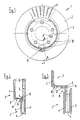
- a brake disc designated in its entirety by 1 consists of a friction ring 2 and a brake disc chamber 3.
- the friction ring 2 is internally ventilated and sets are composed of an outer and an inner friction ring section 4 or 5, which are connected to one another via webs 6.
- the brake disc cup 3 has a floor 7 and a peripheral wall 8, the inside of the vehicle End portion 9 is connected to the outer portion 4 of the friction ring 2.
- the outer section 4 of the friction ring 2 distributed around the circumference a plurality of circular segment-like depressions 10 on.
- On the outside 11 of the wall 8 of the brake disc chamber 3 is partial or all around a stop 12 (FIG. 3) or a shoulder 13 acting as a stop (Fig. 5) provided.
- the radially inner region 14 of the pot-side section 4 of the friction ring 2 is as a contact surface for connection to the brake disc chamber 3 trained.
- the friction ring 2 is opened the brake disc cup 3 pushed on until the end portion 14 of the outer Friction ring section 4 axially comes to rest against the stop 12 or the shoulder 13. Then an electromagnet in the form of a cylindrical coil, the Outside diameter is slightly smaller than the inside diameter of the Brake disk pot 3, introduced into the interior of the brake disk pot 3.
- the Electromagnetic forming process is carried out by briefly applying an electrical Current of high strength triggered on the coil.
- the fixing of the friction ring 2 on the brake disc cup 3 in a first axial direction takes place through the stop 12 or paragraph 13.
- the end section 9 of the wall 8 of the brake disk cup 3 are bent radially outwards (not shown).
- this will by a free space 16 shown in FIG. 3 in the region of the end section 14 of the outer friction ring section 4 facilitated.
- the free space 16 can be partial or be circumferential.
- the method according to the invention is advantageously a combination different materials for the friction ring 2 on the one hand and the brake disc chamber 3 on the other hand possible.
- the friction ring 2 made of GG-15 and the brake disc chamber are preferred 3 made of an aluminum alloy, which is suitable for the Brake disc 1 results in a lower weight.
- a parking brake designed as a drum brake particle-reinforced AI / MMC can also be used as the pot material, which usually contains about 20 to 30% SiC particles.
- the Friction ring 2 also consist of materials other than GG, e.g. B. also from SiC.
- the manufacturing process according to the invention only requires a casting process, namely for the production of the friction ring 2, with advantages over the known, more complex composite casting process.
- the method according to the invention can friction ring 2 and brake disc cup 3 as easy to edit Raw parts are executed. Because the electromagnetic forming process is contactless works, it is not necessary to edit the joints.
- the invention Brake discs 1 are also characterized a low heat transfer between the thermally highly stressable Friction ring 2 and that formed from a thermally sensitive material Brake disc chamber 3 off.
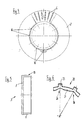
- the connecting element 20 is substantially annular and has a radially inner circumferential ring portion 21 and one Section 22 with cone-shaped elements 23 projecting radially outwards. It consists preferably of a sheet metal material and is easily by a Stamping process produced by which the. Without additional processing steps Final contour of the connecting element 20 is reached.
- the connecting element 20 is when casting the friction ring 2 with its pin-shaped elements 23 in the radially inner free end portion of the outer friction ring portion 4 with poured.
- the one not enclosed by the casting material of the friction ring section 4 radially inner ring portion 21 of the connecting element 20 serves as Connection flange to the brake disc chamber 3.
- the connecting element 20 has one distributed over its inner circumference A plurality of indentations 26 in the shape of a segment of a circle, which correspond to the depressions 10 of the Friction rings 2 of the first embodiment correspond.
- a plurality of indentations 26 in the shape of a segment of a circle, which correspond to the depressions 10 of the Friction rings 2 of the first embodiment correspond.
- the connection between the friction ring 2 and the brake disc chamber 3 indirectly through the connecting element 20, by the deformation areas 8 of the brake disk cup 3 by electromagnetic deformation in the indentations 26 are pressed and thereby a positive in the axial and circumferential direction Create a connection.
Landscapes
- Engineering & Computer Science (AREA)
- General Engineering & Computer Science (AREA)
- Mechanical Engineering (AREA)
- Braking Arrangements (AREA)
Abstract
Description
- Fig. 1
- eine erfindungsgemäß hergestellte Bremsscheibe in der Seitenansicht,
- Fig. 2
- eine Darstellung des Gegenstands von Fig. 1 entlang der Schnittverlaufslinie II-II in Fig. 1,
- Fig. 3
- eine vergrößerte Schnittdarstellung entlang der Schnittverlaufslinie III-III in Fig. 1,
- Fig. 4
- eine Seitenansicht auf den Reibring der erfindungsgemäß hergestellten Bremsscheibe,
- Fig. 5
- eine Schnittdarstellung durch ein weiteres Ausführungsbeispiel eines Bremsscheibentopfes einer erfindungsgemäß hergestellten Bremsscheibe und
- Fig. 6
- eine schematische Teildarstellung eines Verbindungselementes zwischen Reibring und Bremsscheibentopf eines weiteren Ausführungsbeispiels der Erfindung.
Claims (8)
- Verfahren zur Herstellung einer einen Reibring und einen Bremsscheibentopf aufweisenden Bremsscheibe für ein Kraftfahrzeug,
dadurch gekennzeichnet, dass Reibring (2) und Bremsscheibentopf (3) durch elektromagnetisches Umformen miteinander verbunden werden. - Verfahren nach Anspruch 1,
dadurch gekennzeichnet, dass zur Durchführung des elektromagnetischen Umformens eine im wesentlichen zylindrische Spule zur Erzeugung eines elektromagnetischen Feldes in das Innere des Bremsscheibentopfes (3) eingebracht wird, wobei der Außendurchmesser der Spule geringfügig kleiner ist als der Innendurchmesser des Bremsscheibentopfes (3). - Verfahren nach Anspruch 1 und/oder 2,
dadurch gekennzeichnet, dass der Reibring (2), der an seinem radial innenliegenden, auf den Bremsscheibentopf (3) zuweisenden Bereich (14) wenigstens eine Vertiefung (10) aufweist, vor der Verbindung mit dem Bremsscheibentopf (3) auf diesen aufgeschoben wird und durch das elektromagnetische Umformen derjenige Bereich (15) des Bremsscheibentopfes (3), der benachbart zur Vertiefung (10) des Reibringes (2) ist, so in Richtung der Vertiefung (10) verformt wird, dass sich ein Formschluss zwischen Reibring (2) und Bremsscheibentopf (3) ergibt. - Verfahren nach einem der vorgenannten Ansprüche,
dadurch gekennzeichnet, dass nach dem Aufschieben des Reibringes (2) auf den Bremsscheibentopf (3) der freie Endabschnitt (9) des Bremsscheibentopfes (3) durch das elektromagnetische Umformen radial nach außen abgebogen wird. - Verfahren nach Anspruch 4,
dadurch gekennzeichnet, daß zumindest an einem Teil des Umfanges des radial innenliegenden Bereiches (14) des Reibringes (2) ein Freiraum (16) vorgesehen ist, in den Material des freien Endabschnittes (9) hineinverlagert wird. - Verfahren nach einem der vorgenannten Ansprüche,
dadurch gekennzeichnet, dass der Bremsscheibentopf (3) an der Außenseite (11) seiner Topfwandung (8) einen Anschlag (12, 13) aufweist und der Reibring (2) vor der Verbindung mit dem Bremsscheibentopf (3) so weit auf diesen aufgeschoben wird, bis er am Anschlag (12, 13) anliegt. - Verfahren nach Anspruch 1 und/oder 2,
dadurch gekennzeichnet, dass in den Reibring (2) ein Verbindungselement (20) eingegossen wird, das an seinem radial innenliegenden, auf den Bremsscheibentopf (3) zuweisenden Bereich wenigstens eine Einbuchtung (26) aufweist, wobei das Verbindungselement (20) vor der Verbindung mit dem Bremsscheibentopf (3) auf diesen aufgeschoben wird und durch das elektromagnetische Umformen derjenige Bereich (15) des Bremsscheibentopfes (3), der benachbart zur Einbuchtung (26) des Verbindungselementes (20) ist, so in Richtung der Einbuchtung (26) verformt wird, dass sich ein Formschluss zwischen Verbindungselement (20) und Bremsscheibentopf (3) ergibt. - Verfahren nach einem der vorgenannten Ansprüche,
dadurch gekennzeichnet, dass der Bremsscheibentopf (3) aus einem Leichtmetall oder einer Leichtmetall-Legierung und der Reibring (2) aus Grauguss besteht.
Applications Claiming Priority (2)
| Application Number | Priority Date | Filing Date | Title |
|---|---|---|---|
| DE10008191 | 2000-02-23 | ||
| DE10008191 | 2000-02-23 |
Publications (2)
| Publication Number | Publication Date |
|---|---|
| EP1128084A2 true EP1128084A2 (de) | 2001-08-29 |
| EP1128084A3 EP1128084A3 (de) | 2003-10-29 |
Family
ID=7631926
Family Applications (1)
| Application Number | Title | Priority Date | Filing Date |
|---|---|---|---|
| EP01102167A Withdrawn EP1128084A3 (de) | 2000-02-23 | 2001-02-02 | Verfahren zur Herstellung einer Bremsscheibe |
Country Status (1)
| Country | Link |
|---|---|
| EP (1) | EP1128084A3 (de) |
Cited By (5)
| Publication number | Priority date | Publication date | Assignee | Title |
|---|---|---|---|---|
| EP1355075A3 (de) * | 2002-04-19 | 2004-06-30 | Bayerische Motoren Werke Aktiengesellschaft | Verbund-Bremsscheibe für eine Fahrzeug-Scheibenbremse |
| WO2012101561A1 (en) | 2011-01-26 | 2012-08-02 | Freni Brembo S.P.A. | Disc for disc brakes |
| DE102007053576B4 (de) * | 2007-11-09 | 2017-08-03 | Dr. Ing. H.C. F. Porsche Aktiengesellschaft | Bremsvorrichtung |
| DE102016103604A1 (de) * | 2016-03-01 | 2017-09-07 | Dr. Ing. H.C. F. Porsche Aktiengesellschaft | Bremsscheibenvorrichtung für ein Fahrzeug |
| IT201900025222A1 (it) | 2019-12-23 | 2021-06-23 | Freni Brembo Spa | Disco di freno a disco, freno a disco e metodo di produzione |
Family Cites Families (5)
| Publication number | Priority date | Publication date | Assignee | Title |
|---|---|---|---|---|
| DE2263643A1 (de) * | 1972-12-27 | 1974-07-04 | Josef Matthias Fuerlinger | Verfahren zur herstellung eines gegossenen werkstueckes |
| EP0028393B1 (de) * | 1979-10-31 | 1984-08-08 | Stahlschmidt & Maiworm GmbH & Co.KG | Kraftfahrzeugrad |
| JP2989033B2 (ja) * | 1991-05-30 | 1999-12-13 | 昭和アルミニウム株式会社 | 管状継手部を有するアルミニウム材相互の電磁接合方法 |
| DE4419757A1 (de) * | 1994-06-06 | 1995-12-07 | Teves Gmbh Alfred | Bremsscheibe |
| DE19830666B4 (de) * | 1998-07-09 | 2004-02-05 | Daimlerchrysler Ag | Bremsscheibe, insbesondere für ein Kraftfahrzeug |
-
2001
- 2001-02-02 EP EP01102167A patent/EP1128084A3/de not_active Withdrawn
Non-Patent Citations (1)
| Title |
|---|
| Druckschrift Robert N.Stauffer, Electromagnetic Metal Forming, Manufacturing Engineering, Februar 1978, Seiten 74 bis 76 |
Cited By (7)
| Publication number | Priority date | Publication date | Assignee | Title |
|---|---|---|---|---|
| EP1355075A3 (de) * | 2002-04-19 | 2004-06-30 | Bayerische Motoren Werke Aktiengesellschaft | Verbund-Bremsscheibe für eine Fahrzeug-Scheibenbremse |
| DE102007053576B4 (de) * | 2007-11-09 | 2017-08-03 | Dr. Ing. H.C. F. Porsche Aktiengesellschaft | Bremsvorrichtung |
| WO2012101561A1 (en) | 2011-01-26 | 2012-08-02 | Freni Brembo S.P.A. | Disc for disc brakes |
| US9695895B2 (en) | 2011-01-26 | 2017-07-04 | Freni Brembo S.P.A. | Disc for disc brakes |
| DE102016103604A1 (de) * | 2016-03-01 | 2017-09-07 | Dr. Ing. H.C. F. Porsche Aktiengesellschaft | Bremsscheibenvorrichtung für ein Fahrzeug |
| IT201900025222A1 (it) | 2019-12-23 | 2021-06-23 | Freni Brembo Spa | Disco di freno a disco, freno a disco e metodo di produzione |
| US12338867B2 (en) | 2019-12-23 | 2025-06-24 | Brembo S.P.A. | Disk brake disk, disk brake and manufacturing method |
Also Published As
| Publication number | Publication date |
|---|---|
| EP1128084A3 (de) | 2003-10-29 |
Similar Documents
| Publication | Publication Date | Title |
|---|---|---|
| WO1996041967A1 (de) | Bremsscheibe | |
| EP0265663A1 (de) | Verfahren zur Herstellung einer gebauten Nockenwelle sowie gebaute Nockenwelle aus einem Wellenrohr und aufgeschobenen Elementen | |
| EP1719572A2 (de) | Verfahren zum Verschweissen eines Tellerrads mit einem Ausgleichsgehäuse eines Getriebes | |
| EP3662174B1 (de) | Bremsscheibe und verfahren zur herstellung einer bremsscheibe | |
| EP0521843B1 (de) | Reibring | |
| DE102019114697B4 (de) | Verbundmetallflexplatte | |
| JPS63318363A (ja) | 伝動要素が押広げ加工によつて固定される中空軸 | |
| DE3818812A1 (de) | Kupplungsscheibe mit zweigeteilter nabe | |
| DE102016115022A1 (de) | Bremsscheibe und Verfahren zu deren Herstellung | |
| EP2263813B1 (de) | Verfahren zur Herstellung einer Bremsscheibe und nach dem Verfahren hergestellte Bremsscheibe | |
| EP1128083A2 (de) | Verfahren zur Herstellung einer Bremsscheibe | |
| EP1128084A2 (de) | Verfahren zur Herstellung einer Bremsscheibe | |
| EP0292468A2 (de) | Verfahren und Vorrichtung zum Herstellen eines Reib-bzw. Gleitkörpers | |
| WO2014095873A1 (de) | Drückgewalzte bremsscheibe | |
| DE102017115712A1 (de) | Verbundbremsscheibe | |
| DE102009013964B4 (de) | Bremsscheibe | |
| EP1658912B1 (de) | Verfahren zur Herstellung eines Metallteils eines Kunststoff-Metall-Verbundteiles und ein nach dem Verfahren hergestelltes Metallteil | |
| DE102008040127A1 (de) | Ausgestaltung einer Niete | |
| DE102018120125A1 (de) | Gebaute Bremsscheibe und Verfahren zur Herstellung einer solchen Bremsscheibe | |
| DE10024819A1 (de) | Verfahren zur Herstellung einer Bremsscheibe | |
| EP1162384A2 (de) | Fahrzeug-Bremsscheibe, deren Reibring und Bremsscheibentopf aus unterschiedlichen Werkstoffen besteht | |
| EP2478244B1 (de) | Schaltmuffe für ein schaltgetriebe | |
| DE19932810C2 (de) | Verfahren zur Herstellung einer Nockenwelle und danach hergestellte Nockenwelle | |
| EP4145011B1 (de) | Bremseinheit und verfahren zu deren herstellung | |
| DE102015016930A1 (de) | Verfahren zum Herstellen einer Verbundbremsscheibe |
Legal Events
| Date | Code | Title | Description |
|---|---|---|---|
| PUAI | Public reference made under article 153(3) epc to a published international application that has entered the european phase |
Free format text: ORIGINAL CODE: 0009012 |
|
| AK | Designated contracting states |
Kind code of ref document: A2 Designated state(s): AT BE CH CY DE DK ES FI FR GB GR IE IT LI LU MC NL PT SE TR |
|
| AX | Request for extension of the european patent |
Free format text: AL;LT;LV;MK;RO;SI |
|
| PUAL | Search report despatched |
Free format text: ORIGINAL CODE: 0009013 |
|
| STAA | Information on the status of an ep patent application or granted ep patent |
Free format text: STATUS: THE APPLICATION HAS BEEN WITHDRAWN |
|
| AK | Designated contracting states |
Kind code of ref document: A3 Designated state(s): AT BE CH CY DE DK ES FI FR GB GR IE IT LI LU MC NL PT SE TR |
|
| AX | Request for extension of the european patent |
Extension state: AL LT LV MK RO SI |
|
| 18W | Application withdrawn |
Effective date: 20030925 |