EP1128082A2 - Drum brake device - Google Patents
Drum brake device Download PDFInfo
- Publication number
- EP1128082A2 EP1128082A2 EP01104754A EP01104754A EP1128082A2 EP 1128082 A2 EP1128082 A2 EP 1128082A2 EP 01104754 A EP01104754 A EP 01104754A EP 01104754 A EP01104754 A EP 01104754A EP 1128082 A2 EP1128082 A2 EP 1128082A2
- Authority
- EP
- European Patent Office
- Prior art keywords
- brake
- shoe
- drum
- adjustment
- brake shoes
- Prior art date
- Legal status (The legal status is an assumption and is not a legal conclusion. Google has not performed a legal analysis and makes no representation as to the accuracy of the status listed.)
- Withdrawn
Links
Images



Classifications
-
- F—MECHANICAL ENGINEERING; LIGHTING; HEATING; WEAPONS; BLASTING
- F16—ENGINEERING ELEMENTS AND UNITS; GENERAL MEASURES FOR PRODUCING AND MAINTAINING EFFECTIVE FUNCTIONING OF MACHINES OR INSTALLATIONS; THERMAL INSULATION IN GENERAL
- F16D—COUPLINGS FOR TRANSMITTING ROTATION; CLUTCHES; BRAKES
- F16D51/00—Brakes with outwardly-movable braking members co-operating with the inner surface of a drum or the like
- F16D51/16—Brakes with outwardly-movable braking members co-operating with the inner surface of a drum or the like shaped as brake-shoes pivoted on a fixed or nearly-fixed axis
- F16D51/18—Brakes with outwardly-movable braking members co-operating with the inner surface of a drum or the like shaped as brake-shoes pivoted on a fixed or nearly-fixed axis with two brake-shoes
- F16D51/26—Brakes with outwardly-movable braking members co-operating with the inner surface of a drum or the like shaped as brake-shoes pivoted on a fixed or nearly-fixed axis with two brake-shoes both extending in the same direction from their pivots
- F16D51/30—Brakes with outwardly-movable braking members co-operating with the inner surface of a drum or the like shaped as brake-shoes pivoted on a fixed or nearly-fixed axis with two brake-shoes both extending in the same direction from their pivots fluid actuated
-
- F—MECHANICAL ENGINEERING; LIGHTING; HEATING; WEAPONS; BLASTING
- F16—ENGINEERING ELEMENTS AND UNITS; GENERAL MEASURES FOR PRODUCING AND MAINTAINING EFFECTIVE FUNCTIONING OF MACHINES OR INSTALLATIONS; THERMAL INSULATION IN GENERAL
- F16D—COUPLINGS FOR TRANSMITTING ROTATION; CLUTCHES; BRAKES
- F16D65/00—Parts or details
- F16D65/02—Braking members; Mounting thereof
- F16D65/04—Bands, shoes or pads; Pivots or supporting members therefor
- F16D65/08—Bands, shoes or pads; Pivots or supporting members therefor for internally-engaging brakes
- F16D65/09—Pivots or supporting members therefor
- F16D65/091—Pivots or supporting members therefor for axially holding the segments
-
- F—MECHANICAL ENGINEERING; LIGHTING; HEATING; WEAPONS; BLASTING
- F16—ENGINEERING ELEMENTS AND UNITS; GENERAL MEASURES FOR PRODUCING AND MAINTAINING EFFECTIVE FUNCTIONING OF MACHINES OR INSTALLATIONS; THERMAL INSULATION IN GENERAL
- F16D—COUPLINGS FOR TRANSMITTING ROTATION; CLUTCHES; BRAKES
- F16D51/00—Brakes with outwardly-movable braking members co-operating with the inner surface of a drum or the like
- F16D51/46—Self-tightening brakes with pivoted brake shoes, i.e. the braked member increases the braking action
- F16D51/48—Self-tightening brakes with pivoted brake shoes, i.e. the braked member increases the braking action with two linked or directly-interacting brake shoes
- F16D51/52—Self-tightening brakes with pivoted brake shoes, i.e. the braked member increases the braking action with two linked or directly-interacting brake shoes fluid actuated
-
- F—MECHANICAL ENGINEERING; LIGHTING; HEATING; WEAPONS; BLASTING
- F16—ENGINEERING ELEMENTS AND UNITS; GENERAL MEASURES FOR PRODUCING AND MAINTAINING EFFECTIVE FUNCTIONING OF MACHINES OR INSTALLATIONS; THERMAL INSULATION IN GENERAL
- F16D—COUPLINGS FOR TRANSMITTING ROTATION; CLUTCHES; BRAKES
- F16D65/00—Parts or details
- F16D65/14—Actuating mechanisms for brakes; Means for initiating operation at a predetermined position
- F16D65/16—Actuating mechanisms for brakes; Means for initiating operation at a predetermined position arranged in or on the brake
- F16D65/22—Actuating mechanisms for brakes; Means for initiating operation at a predetermined position arranged in or on the brake adapted for pressing members apart, e.g. for drum brakes
-
- F—MECHANICAL ENGINEERING; LIGHTING; HEATING; WEAPONS; BLASTING
- F16—ENGINEERING ELEMENTS AND UNITS; GENERAL MEASURES FOR PRODUCING AND MAINTAINING EFFECTIVE FUNCTIONING OF MACHINES OR INSTALLATIONS; THERMAL INSULATION IN GENERAL
- F16D—COUPLINGS FOR TRANSMITTING ROTATION; CLUTCHES; BRAKES
- F16D65/00—Parts or details
- F16D65/38—Slack adjusters
- F16D65/40—Slack adjusters mechanical
- F16D65/52—Slack adjusters mechanical self-acting in one direction for adjusting excessive play
- F16D65/56—Slack adjusters mechanical self-acting in one direction for adjusting excessive play with screw-thread and nut
- F16D65/561—Slack adjusters mechanical self-acting in one direction for adjusting excessive play with screw-thread and nut for mounting within the confines of a drum brake
- F16D65/563—Slack adjusters mechanical self-acting in one direction for adjusting excessive play with screw-thread and nut for mounting within the confines of a drum brake arranged adjacent to service brake actuator, e.g. on parking brake lever, and not subjected to service brake force
-
- F—MECHANICAL ENGINEERING; LIGHTING; HEATING; WEAPONS; BLASTING
- F16—ENGINEERING ELEMENTS AND UNITS; GENERAL MEASURES FOR PRODUCING AND MAINTAINING EFFECTIVE FUNCTIONING OF MACHINES OR INSTALLATIONS; THERMAL INSULATION IN GENERAL
- F16D—COUPLINGS FOR TRANSMITTING ROTATION; CLUTCHES; BRAKES
- F16D65/00—Parts or details
- F16D65/38—Slack adjusters
- F16D65/40—Slack adjusters mechanical
- F16D65/52—Slack adjusters mechanical self-acting in one direction for adjusting excessive play
- F16D65/56—Slack adjusters mechanical self-acting in one direction for adjusting excessive play with screw-thread and nut
- F16D65/561—Slack adjusters mechanical self-acting in one direction for adjusting excessive play with screw-thread and nut for mounting within the confines of a drum brake
- F16D65/565—Slack adjusters mechanical self-acting in one direction for adjusting excessive play with screw-thread and nut for mounting within the confines of a drum brake arranged diametrically opposite to service brake actuator, and subjected to service brake force
-
- F—MECHANICAL ENGINEERING; LIGHTING; HEATING; WEAPONS; BLASTING
- F16—ENGINEERING ELEMENTS AND UNITS; GENERAL MEASURES FOR PRODUCING AND MAINTAINING EFFECTIVE FUNCTIONING OF MACHINES OR INSTALLATIONS; THERMAL INSULATION IN GENERAL
- F16D—COUPLINGS FOR TRANSMITTING ROTATION; CLUTCHES; BRAKES
- F16D2121/00—Type of actuator operation force
- F16D2121/02—Fluid pressure
-
- F—MECHANICAL ENGINEERING; LIGHTING; HEATING; WEAPONS; BLASTING
- F16—ENGINEERING ELEMENTS AND UNITS; GENERAL MEASURES FOR PRODUCING AND MAINTAINING EFFECTIVE FUNCTIONING OF MACHINES OR INSTALLATIONS; THERMAL INSULATION IN GENERAL
- F16D—COUPLINGS FOR TRANSMITTING ROTATION; CLUTCHES; BRAKES
- F16D2121/00—Type of actuator operation force
- F16D2121/14—Mechanical
-
- F—MECHANICAL ENGINEERING; LIGHTING; HEATING; WEAPONS; BLASTING
- F16—ENGINEERING ELEMENTS AND UNITS; GENERAL MEASURES FOR PRODUCING AND MAINTAINING EFFECTIVE FUNCTIONING OF MACHINES OR INSTALLATIONS; THERMAL INSULATION IN GENERAL
- F16D—COUPLINGS FOR TRANSMITTING ROTATION; CLUTCHES; BRAKES
- F16D2125/00—Components of actuators
- F16D2125/18—Mechanical mechanisms
- F16D2125/58—Mechanical mechanisms transmitting linear movement
- F16D2125/64—Levers
Definitions
- This invention relates to a drum brake device with a single service brake shoe-actuator, intended in particular to provide a braking force equivalent to that of a duo-two leading (hereinafter "D2L”) type drum brake with two service brake shoe-actuators.
- D2L duo-two leading
- a drum brake device with a single shoe-actuator capable of providing a braking force equivalent to that of a D2L type drum brake device is disclosed by this applicant in the Japanese Patent Laid-Open Provisional Publication No. 10-47396.
- the above-described conventional drum brake device has the following limitations.
- the brake shoes 40, 50 move relative to the pivot section 61, 61, and frictionally engage with the rotating brake drum. Thereafter, the brake shoes 40, 50 generate the braking force by being abutted against and supported by either the first or the second anchor 11, 29.
- the brake shoes 40, 50 move together with the brake drum, the other adjacent ends 60b, 60b of both pivot levers 60, 60 slide on the second anchors 11, 11 while supporting the operation force applied by the wheel cylinder 20, i.e., shoe-actuator. Therefore, the conventional drum brake has an unavoidable decrease in braking efficiency due to the resistance at the sliding portions and the rotational resistance at the pivot sections 61, 61.
- the sliding resistance at the other adjacent ends 60b, 60b and the rotational resistance at the pivot sections 61, 61 is increased proportional to the operational force of the wheel cylinder 20, i.e., shoe-actuator, which leads to a lower durability of the device due to wearing and fatigue in these sections.
- a thrust force from the pivot levers 60, 60 acts on the second anchors 11, 11 incorporating the shoe clearance adjustment devices. If the automatic shoe clearance adjustment devices, that keep the clearances between the brake drum and linings 43, 43 constant, are utilized, the thrust force affects the automatic adjustment action as a variance factor which tends to alter/influence the clearances between the brake drum and the linings 43, 53.
- drum brake device as defined in claim 1.
- This invention is based on a drum brake device comprising: a pair of brake shoes positioned opposite to each other and to be frictionally engageable with an inner circumferential surface of a brake drum; a first anchor positioned between first adjacent ends of the brake shoes; a second anchor positioned between second adjacent ends of the brake shoes opposite said first adjacent ends; a pivot lever with an intermediate portion pivotally supported on a first one of the brake shoes at a pivot section; a shoe-actuator positioned adjacent to the first anchor and being disposed between one end of the pivot lever and a second one of the brake shoes; and a strut positioned between and functionally engaged with a second end of the pivot lever and the second one of the brake shoes.
- This invention is characterized in that an application force of the shoe-actuator is transmitted to the first one of the brake shoes via the pivot section of the pivot lever and transmitted to the second one of the brake shoes directly from said shoe-actuator and indirectly via the strut.
- the pivot lever When the brake shoes frictionally engage and interact with the brake drum during braking, the pivot lever is supported by the strut free to swing in order to smoothly move together with the brake shoes, thereby providing a D2L type drum brake device with high braking efficiency despite the use of a single shoe-actuator.
- the pivot lever smoothly moves until it contacts with one of the brake shoes supported by the anchor, which eliminates overload on the pivot and abutment sections thereof and provides a highly durable device.
- This invention enables the downsizing of the pivot lever and strut for realizing the drum brake with one shoe-actuator for the service brake, which reduces the cost of manufacturing and the overall weight of the device.
- the parking brake mechanism of this invention can easily be installed.
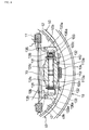
- Figure 1 is a plan view of a drum brake device incorporating a pair of brake shoes 40, 50 frictionally engageable with an inner circumferential surface of a brake drum not shown in the figures.
- First anchors 30, 30 incorporating shoe clearance adjustment devices are positioned adjacent to but closer to a brake center than the wheel cylinder 20, which is combined with an anchor body 22 integrally extended from a cylinder body 21.
- a second anchor 12 is positioned on a lower portion of the back plate 10.
- This drum brake device further comprises a pivot lever 60 and a strut 70 for transmitting an operation force of the wheel cylinder 20 to both brake shoes 40, 50.
- the pair of brake shoes 40, 50 is configured so that shoe rims 41, 51 are fixed on shoe webs 42, 52 respectively to form a T-shaped cross-section.
- the linings 43, 53 are affixed on the peripheral surfaces of the shoe rims 41, 51.
- one brake shoe 40 has one end 40a (hereinafter “upper end 40a”) which abuts against and engages with a left adjustment bolt 31 as a screw member of the shoe clearance adjustment devices constituting the first anchor 30, while the other end 40b(hereinafter “lower end 40b”) abuts against and engages with a side end surface of the second anchor 12.
- the other brake shoe 50 has its one end 50a (hereinafter “upper end 50a”) which operationally engages with a piston 23 of the wheel cylinder 20; its other end 50b (hereinafter “lower end 50b”) abuts against and engages with a flat side end surface of the second anchor 12; while an upper intermediate portion 50c closer to the upper end 50a abuts against and engages with a right adjustment bolt 31 as a screw member just like the brake shoe 40.
- upper end 50a which operationally engages with a piston 23 of the wheel cylinder 20
- lower end 50b abuts against and engages with a flat side end surface of the second anchor 12
- an upper intermediate portion 50c closer to the upper end 50a abuts against and engages with a right adjustment bolt 31 as a screw member just like the brake shoe 40.
- a prime characteristic of this invention is to implement a mechanical expander comprising one pivot lever 60 and a strut 70 as a means to transmit an application force of the wheel cylinder 20 to the pair of the brake shoes 40, 50 as the outward force of the brake shoes 40, 50.
- the arc-shaped pivot lever 60 is superposed on the shoe web 42, in that an intermediate portion of the pivot lever 60 is pivotally supported at an intermediate portion of the shoe web 42 and one end 60a (hereinafter "upper end 60a") operationally engages with the left piston 23 of the wheel cylinder 20.
- the strut 70 is positioned between the other end 60b (hereinafter “lower end 60b") and an intermediate portion 50d of the brake shoe 50 closer to the lower end 50b thereof, wherein notched grooves are formed with respect to all three of the aforementioned elements to functionally engage each other.
- the engagement is maintained by a compression spring 24 disposed between the pistons 23 and 23.
- Figure 3 is a cross-sectional view of the pivot section 61 between the brake shoe 40 and the pivot lever 60, wherein a cylindrical protuberance 60d projecting toward the shoe web 42 is formed on the intermediate portion of the pivot lever 60, and the protuberance 60d is pivotally fit into a circular hole 42a formed on the shoe web 42.
- a circular hole may be formed on the pivot lever 60 and a protuberance may be formed on the shoe web 42 to constitute the pivot structure.
- an independent separate pin may be utilized to constitute the same effect as the protuberance.
- the pivot section 61 between the brake shoe 40 and the pivot lever 60 is held by a shoe hold pin 81, being rotatably provided on the back plate 10 such that an intermediate portion thereof is freely penetrating through the protuberance 60d, and a plate spring 82 is latched at the other side of the pin 81 and installed on the pivot lever 60 in a compressed state.
- a publicly known shoe hold mechanism 80 is utilized to resiliently hold the brake shoe 40 on the back plate 10 and the pivot lever 60 on the shoe web 42.
- the shoe hold pin 81 may be replaced with a bolt-like member where one end thereof is fixed in the back plate 10 and the other end portion thereof is held with upper and lower nuts so as to movably hold the brake shoe 40 and the pivot lever 6.
- the brake shoe 50 is resiliently held on the back plate 10 with the publicly known shoe hold mechanism 80.
- Figure 4 is an enlarged view of the left half of the first anchors 30, 30 incorporating the shoe clearance adjustment devices.
- the structure's right half is symmetrical relative to the left half except that the adjustment bolt 31 and a toothed ring 32 are reverse threaded; therefore, the explanation is omitted.
- a through bore 22a is formed in the anchor body 22, into which an externally threaded shaft 31c of the adjustment bolt 31 is slidably fit.
- a notched groove 31a having a stepped shape is formed at the left side of the adjustment bolt 31, and the upper end 40a of the shoe web 42 abuts against the bottom of the notched groove 31a and the intermediate portion 60c of the pivot lever 60 closer to the upper end 60a thereof engages with the bottom of the notched groove 31a with a clearance.
- a toothed ring 32 screwed on the external threaded shaft 31c of the adjustment bolt 31 has plural small teeth on its circumferential surface, and its right side surface abuts against the left side surface of the anchor body 22 so as to restrict the retract position of the adjustment bolt 31 relative to the anchor body 22 and so as to be capable to vary the displacement of the adjustment bolt 31 relative to the anchor body 22 by rotating the toothed ring 32.
- the first anchor 30 incorporated with the shoe clearance adjustment device comprises the anchor body 22 into which the adjustment bolt 31 is inserted and the toothed ring 32 screwed onto the adjustment bolt 31.
- a plug 19 installed on the back plate 10 is to be removed, and then a tool such as a screw driver is inserted from the outside of the brake to rotate the toothed ring 32 in order to screw the adjustment bolt 31 into or out from the toothed ring 32, thereby enabling the manual adjustment of the clearance.
- An adjustment lever 33 and an adjustment spring 34 in the shoe clearance adjustment device constitute an automatic shoe clearance adjustment device that automatically adjusts the clearance between the lining 43 and the brake drum.
- FIG. 5 shows a plan view of the adjustment lever 33.
- the adjustment lever 33 is an almost Y-shaped flat plate, a first arm 33a has a pin hole 33b while a second arm 33c has a bent end making a ratchet engagement with the toothed ring 32.
- a third arm 33d which also has a bent end having a hole or slit to engage a hook of the adjustment spring 34.
- the adjustment lever 33 is pivotally supported on the brake shoe 40 by a pin 35 extending through the pin hole 33b as shown in Figure 1.
- the adjustment spring 34 extended between the third arm 33d and the pivot lever 60 constantly applies the adjustment lever 33 with a counterclockwise turning force around the pin 35 and the second arm 33c is biased toward the toothed ring 32 in that the abutment piece 33e is urged to abut and engage the stepped surface 31b of the adjustment bolt 31 as shown in Figure 4.
- An outline of the right adjustment lever 33 is symmetrical relative to the left one, and the adjustment spring 34 is extended between the adjustment lever 33 and the shoe web 52 so as to apply the adjustment lever 33 with a clockwise turning force around the pin 35 and the second arm 33c is biased toward the toothed ring 32 into the ratchet engagement therewith.
- a first shoe return spring 16 is extended between the brake shoes 40 and 50 in close vicinity to the wheel cylinder 20 while a second shoe return spring 17 is extended between the brake shoes 40 and 50 in close vicinity to the second anchor 12.
- a spring force of the first and the second shoe return springs 16, 17 is specified such that a momentum acting on the brake shoe 40 around the pivot point 61 of the brake shoe 40 acting as a fulcrum due to the first and the second shoe return springs 16, 17 is adjusted to be larger at the lower side 40b than at the upper side 40a.
- the brake shoe 50 moves outward with the point of abutment with the second anchor 12 as the fulcrum due to the application forces of the piston 23, 23 transmitted from the upper ends 50a and the intermediate portion 50d closer to the lower end 50b.
- the pivot lever 60 moves counterclockwise with the point of abutment with the strut 70 as the fulcrum by the operational force of the wheel cylinder 20; the force transmitted via the pivot section 61 causes the brake shoe 40 to move outward with the abutment point with the second anchor 12 as the fulcrum.
- the pair of the brake shoes 40, 50 provide two-leading braking action in the direction B, too.
- both brake shoes 40, 50 have a self-servo effect when the vehicle is moving forward or backward, thereby functioning as leading shoes with self-servo effect like a D2L type drum brake device, which offers a stable braking effect.
- the strut 70 is able to swing thereby allowing smooth movement of the two, i.e., the brake shoe 40 and the pivot lever 60, which avoids decreasing the braking efficiency and provides an increase of the device's durability.
- the brake shoes 40, 50 while in the service brake operation, spread open with the point of abutment between the lower adjacent ends 40b, 50b and the second anchor 12, thereby frictionally engaging with the brake drum, not shown in the figures.
- the pin 35 moves together therewith.
- the abutment piece 33e of the adjustment lever 33 is forced against the stepped surface 31b of the adjustment bolt 31 by an urging force of the adjustment spring 34, the second arm 33c pivots counterclockwise.
- the total displacement of the brake shoe 40 increases, which leads to an increase of the amount of rotation of the bent end at the second arm 33c of the adjustment lever 33. If the amount of rotation of the adjustment lever 33 exceeds one tooth pitch of the toothed ring 32, the second arm 33c rotates the toothed ring 32 so as to protrude the adjustment bolt 31 from the anchor body 22, thereby automatically adjusting the brake to keep a constant clearance between the lining 43 and the brake drum.
- first anchors 30, 30 incorporating the shoe clearance adjustment devices are positioned adjacent to but closer to the brake center than the wheel cylinder 20.
- first anchors 130, 130 are positioned adjacent to but farther away from the brake center than the wheel cylinder 20 as shown in Figure 7, and a second anchor 112 is incorporated with the automatic shoe clearance adjustment devices.
- a shoe expander operable upon activating the parking brake is positioned closer to the brake center than the wheel cylinder 20. Detailed descriptions of the same are explained herein.
- An anchor body 122 integrally formed with the cylinder body 21 is positioned adjacent to but farther away from the brake center than the wheel cylinder 20.
- the anchor body 122 has a horizontal through bore 122a formed therein, into which heads 137, 137 are fit respectively, thereby constituting the first anchors 130, 130.
- the upper adjacent ends 40a, 50a of the brake shoes 40, 50 abut against and respectively engage with the heads 137, 137.
- Each abutment section between the heads 137, 137 and the upper ends 40a, 50a is in convex-concave-like engagement whereby the radius of curvature of the upper ends is designed a bit larger than that of the heads 137, 137. If the convex-concave-like engagement between the heads 137, 137 and the upper ends 40a, 50a is reversed, the radius of curvature relative to the upper ends 40a, 50a should be designed a bit larger.
- the upper ends 40a, 50a may be directly abutted against and engaged with the anchor body 122.
- a second anchor 112 having the shoe clearance adjustment devices is explained with reference to Figures 7 and 8.
- the second anchor 112 comprises an anchor body 113 fixed on the back plate 10, a pair of adjustment bolts 131, 131 screwed into the anchor body 113, and sleeves 136, 136 relatively rotatably interconnected to the adjustment bolts 131, 131.
- adjustment levers 133, 133, pins 135, 135, and an adjustment spring 134 are added to constitute an automatic shoe clearance adjustment device having reverse threaded right and left adjustment bolts 131, 131.
- the adjustment bolt 131 formed integrally with a toothed ring 132 at its intermediate portion has an external thread shaft 131c, its one side screwed and fit in an internal thread 113a of the anchor body 113 and the other side of the shaft 131c being relatively rotatably fit in a blind hole of the sleeve 136.
- the lower end 40b of the brake shoe 40 and the intermediate portion of the adjustment lever 133 abut against and engage with a notched groove 136a of the sleeve 136.
- the adjustment lever 133 is a substantially L-shaped member, a first arm 133a is pivotally supported on the shoe web 42 by a pin 135 and the urging force of the adjustment spring 134 extended between the adjustment levers 133 and 133 constantly transmits the clockwise turning force with the pin 135 acting as the fulcrum to the adjustment lever 133 and a bias force to make the ratchet engagement with the toothed ring 132.
- a structure of a forward pull type parking brake in which the brake lever moves in the direction parallel with a forward moving vehicle is explained with reference to Figures 7 and 9.
- a brake lever 90 is superposed on the shoe web 52, where one end 90a is pivotally supported by the pin 91 while another free end 90c has a U-shaped groove bent in such a manner for allowing hooking a parking brake cable which is not shown in the figures.
- the brake lever 90 has a protrusion 90d on its intermediate portion, which abuts against the inner edge of the shoe web 52, thereby restricting the counterclockwise movement of the brake lever 90 with the pin 91 acting as the fulcrum as shown in Figure 7.
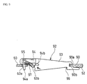
- a strut 92 as a component of this parking brake mechanism, comprises an one shot type automatic stroke adjustment mechanism for automatically adjusting the brake lever 90 stroke, which is positioned adjacent to the wheel cylinder 20 and disposed between the pivot lever 60 and an intermediate portion 90b of the brake lever 90.
- the strut 92 comprises an adjustment plate 93, a bell crank lever 94, a pin 95, an antirattle spring 96, and a lever spring 97.
- a notched groove 93a formed at the right side of the adjustment plate 93 crosses and abuts against the intermediate portion 90b of the brake lever 90.
- the adjustment plate 93 has its intermediate part with small teeth 93b formed thereon and a slotted hole at its left side in which an intermediate portion of the bell crank lever 94 is pivotally supported and is longitudinally movable along the plate surface with the pin 95 as the fulcrum.
- Small teeth 94b are formed on a peripheral surface of a fan-shaped arm at one side of the bell crank lever 94, and the teeth 94b engage with small teeth 93b of the adjustment plate 93 while a cam arm 94a freely fits with a rectangular hole 60e formed on the pivot lever 60.
- a mounting load of these springs is designed so that the mounting load of the anti-rattle spring 96 is larger than that of other springs.
- the spring force of the first and the second shoe return springs 16, 17 extended between the pair of brake shoes 40, 50 is configured such that a momentum around the pivot point 61 of the brake shoe 40 acting as the fulcrum due to the first and the second shoe return springs 16, 17 acting on the brake shoe 40 is adjusted to set that at the upper side 40a larger than that at the lower side 40b as opposed to the first embodiment.
- the application force from the wheel cylinder 20 is transmitted to the brake shoe 50 as an outward force of the brake shoe 50, and the lower end 50b of the brake shoe 50 spreads open, at this time, the pin 135 moves together with the brake shoe 50.
- the right adjustment lever 133 follows the pin 135 movement with the point of abutment with the sleeve 136 by the urging force of the adjustment spring 134. Accordingly, the second arm 133c of the adjustment lever 133 rotates clockwise.
- the total displacement of the amount of rotation of the second arm 133b on the adjustment lever 133 increases. If the amount of that rotation exceeds one tooth pitch of the toothed ring 132, the bolt 131 is rotated in the direction to be protruded from the anchor body 113, thereby automatically adjusting to keep the clearance between the lining 53 and the brake drum, not shown in the figures, constant.
- the brake lever 90 in Figure 7 moves clockwise with the pivot point at the pin 91 at the end 90a, which pushes the rectangular hole 60e on the pivot lever 60 toward the left via the strut 92, thereby generating a counter force pushing the intermediate portion 50c of the brake shoe 50 toward the right via the pin 91.
- Braking after this process is almost identical to the operation as service brake like in the first embodiment, and the explanation of which is omitted here.
- both brake shoes 40, 50 have self-servo effect when the brake drum, not shown in the figures, rotates in any direction, thereby functioning as leading shoes with a self-servo effect like a D2L type drum brake device, which offers a stable braking effect.
- the amount of displacement of the upper end 60a of the pivot lever 60 and of the intermediate portion 50c of the brake shoe 50 increases. If the amount of displacement exceeds the gap between a right end surface of the cam arm 94a and a right end surface of the rectangular hole 60e on the pivot lever 60, the cam arm 94a is pushed outward by the rectangular hole 60e and the adjustment plate 93 follows the outward movement of the brake shoe 50 together with the brake lever 90.
- This invention is not limited to what is described in the first and the second embodiments.
- arrangement of the wheel cylinder 20 and the first anchors 30, 30, 130, 130 in the first and the second embodiments or the structure of the second anchors 12, 112 may be interchanged.
- a parking brake mechanism may be applied in the first embodiment, and a cross-pull type of parking brake mechanism may be easily employed instead of the forward-pull type one.
- This invention has the following advantages.
- the pivot lever is supported by the strut free to swing in order to smoothly move together with the brake shoes, thereby providing a D2L type drum brake device with high braking efficiency despite the use of a single shoe-actuator.
- the pivot lever smoothly moves until it contacts with one of the brake shoes supported by the anchor, which eliminates overload on the pivot and abutment sections thereof and provides a highly durable device.
- This invention enables the downsizing of the pivot lever and strut for realizing the drum brake with one shoe-actuator for the service brake, which reduces the cost of manufacturing and reduces the weight of the device.
- the parking brake mechanism of this invention can easily be installed.
Landscapes
- Engineering & Computer Science (AREA)
- General Engineering & Computer Science (AREA)
- Mechanical Engineering (AREA)
- Braking Arrangements (AREA)
Abstract
Description
Claims (7)
- A drum brake device comprising:a pair of brake shoes (40,50) positioned opposite to each other and to be frictionally engageable with an inner circumferential surface of a brake drum,a first anchor (30) positioned between first adjacent ends (40a,50a) of said brake shoes (40,50),a second anchor (12) positioned between second adjacent ends (40b,50b) of said brake shoes (40,50) opposite said first adjacent ends (40a,50a),a pivot lever (60) with an intermediate portion pivotally supported on a first one (40) of said brake shoes (40,50) at a pivot section (61),a shoe-actuator (20) positioned adjacent to said first anchor (30) and being disposed between one end (60a) of said pivot lever (60) and a second one (50) of said brake shoes (40,50), anda strut (70) positioned between and functionally engaged with a second end (60b) of said pivot lever (60) and the second one (50) of said brake shoes (40,50), whereinan application force of said shoe-actuator (20) is transmitted to said first one (40) of said brake shoes (40,50) via said pivot section (61) of said pivot lever (60) and transmitted to the second one (50) of said brake shoes (40,50) directly by said shoe-actuator (20) and indirectly via said strut (70).
- The drum brake device as claimed in claim 1, further comprising:
a pair of shoe clearance adjustment devices having a screw-mechanism incorporated in one of said first and second anchors that are supporting said pair of brake shoes (40,50). - The drum brake device as claimed in claim 2, wherein said automatic shoe clearance adjustment devices are adapted to sense an amount of movement of said brake shoes (40,50) and to automatically extend a length of said screw-mechanism.
- The drum brake device as claimed in any one of claims 1 to 3, wherein said shoe-actuator is adapted to operate during service brake operation.
- The drum brake device as claimed in any one of claims 1 to 3, wherein said shoe-actuator is a shoe expander adapted to operate during parking brake operation.
- The drum brake device as claimed in claim 5, wherein a stroke adjustment mechanism is included for an adjustment of said shoe expander stroke operating by the parking brake.
- The drum brake device as claimed in claim 6, wherein
said stroke adjustment mechanism is adapted to sense the amount of movement of the brake shoes and to automatically keep a stroke of said shoe expander constant.
Applications Claiming Priority (2)
| Application Number | Priority Date | Filing Date | Title |
|---|---|---|---|
| JP2000049857A JP2001241475A (en) | 2000-02-25 | 2000-02-25 | Drum brake device |
| JP2000049857 | 2000-02-25 |
Publications (2)
| Publication Number | Publication Date |
|---|---|
| EP1128082A2 true EP1128082A2 (en) | 2001-08-29 |
| EP1128082A3 EP1128082A3 (en) | 2003-05-14 |
Family
ID=18571726
Family Applications (1)
| Application Number | Title | Priority Date | Filing Date |
|---|---|---|---|
| EP01104754A Withdrawn EP1128082A3 (en) | 2000-02-25 | 2001-02-26 | Drum brake device |
Country Status (4)
| Country | Link |
|---|---|
| US (1) | US6523652B2 (en) |
| EP (1) | EP1128082A3 (en) |
| JP (1) | JP2001241475A (en) |
| KR (1) | KR20010085561A (en) |
Cited By (1)
| Publication number | Priority date | Publication date | Assignee | Title |
|---|---|---|---|---|
| WO2004007985A1 (en) * | 2002-07-11 | 2004-01-22 | Brakes India Limited | High performance drum brake assembly for automotive braking system |
Families Citing this family (8)
| Publication number | Priority date | Publication date | Assignee | Title |
|---|---|---|---|---|
| JP4207060B2 (en) * | 2006-05-31 | 2009-01-14 | アイシン・エィ・ダブリュ株式会社 | Drawing system |
| US20080149434A1 (en) * | 2006-11-29 | 2008-06-26 | Akebono Corporation (North America) | Parking brake and actuator mechanism |
| US8267227B2 (en) * | 2008-07-22 | 2012-09-18 | Akebono Brake Corporation | Lever assembly featuring blind cable assembly |
| JP5260616B2 (en) * | 2010-10-18 | 2013-08-14 | 曙ブレーキ工業株式会社 | Adjuster mechanism in link type booster |
| IT201600128706A1 (en) * | 2016-12-20 | 2018-06-20 | Freni Brembo Spa | Game adjustment device for a parking brake |
| JP2018169038A (en) * | 2017-03-30 | 2018-11-01 | 株式会社アドヴィックス | Vehicle brake |
| KR102128229B1 (en) * | 2018-08-17 | 2020-06-30 | 현대모비스 주식회사 | Drum break apparatus |
| KR102894771B1 (en) * | 2020-11-25 | 2025-12-04 | 현대모비스 주식회사 | Drum break apparatus |
Family Cites Families (17)
| Publication number | Priority date | Publication date | Assignee | Title |
|---|---|---|---|---|
| US2161641A (en) * | 1937-08-14 | 1939-06-06 | Wagner Electric Corp | Braking mechanism |
| US2280784A (en) * | 1939-03-09 | 1942-04-28 | Edward H Berno | Brake |
| US2251854A (en) * | 1939-03-21 | 1941-08-05 | Automotive Prod Co Ltd | Internal shoe drum brake |
| US2232308A (en) * | 1939-05-01 | 1941-02-18 | Hydraulie Brake Company | Brake |
| US2347239A (en) * | 1941-01-03 | 1944-04-25 | Edward H Berno | Brake mechanism |
| US2396387A (en) * | 1944-09-23 | 1946-03-12 | Gen Motors Corp | Brake |
| US2503489A (en) * | 1945-10-05 | 1950-04-11 | Jr Thomas James | Multiple operated vehicle brake |
| DE8527385U1 (en) * | 1985-09-25 | 1987-01-29 | Lucas Industries P.L.C., Birmingham, West Midlands | Drum brake with low sensitivity |
| US4787487A (en) * | 1987-05-28 | 1988-11-29 | Dico Company, Inc. | Articulated linkage assembly for a surge brake |
| US5275260A (en) * | 1989-09-18 | 1994-01-04 | Kelsey-Hayes Company | Dual mode drum brake assembly |
| US5070968A (en) * | 1989-09-18 | 1991-12-10 | Kelsey-Hayes Company | Leading/trailing drum brake having servo parking brake |
| JP3341143B2 (en) * | 1996-04-04 | 2002-11-05 | 日清紡績株式会社 | Drum brake device |
| US5924529A (en) * | 1996-04-05 | 1999-07-20 | Nisshinbo Industries, Inc. | Drum brake device with single shoe extension device |
| JP3413459B2 (en) * | 1996-08-02 | 2003-06-03 | 日清紡績株式会社 | Drum brake device |
| JP3336218B2 (en) * | 1997-04-03 | 2002-10-21 | 日清紡績株式会社 | Duo servo type drum brake device |
| JP3338949B2 (en) * | 1997-08-05 | 2002-10-28 | 日清紡績株式会社 | Drum brake device |
| JP3341150B2 (en) * | 1998-04-22 | 2002-11-05 | 日清紡績株式会社 | Drum brake device |
-
2000
- 2000-02-25 JP JP2000049857A patent/JP2001241475A/en active Pending
-
2001
- 2001-02-24 KR KR1020010009440A patent/KR20010085561A/en not_active Withdrawn
- 2001-02-26 EP EP01104754A patent/EP1128082A3/en not_active Withdrawn
- 2001-02-26 US US09/792,076 patent/US6523652B2/en not_active Expired - Fee Related
Cited By (3)
| Publication number | Priority date | Publication date | Assignee | Title |
|---|---|---|---|---|
| WO2004007985A1 (en) * | 2002-07-11 | 2004-01-22 | Brakes India Limited | High performance drum brake assembly for automotive braking system |
| GB2407350A (en) * | 2002-07-11 | 2005-04-27 | Brakes India Ltd | High performance drum brake assembly for automotive braking system |
| GB2407350B (en) * | 2002-07-11 | 2005-11-16 | Brakes India Ltd | High performance drum brake assembly for automotive braking system |
Also Published As
| Publication number | Publication date |
|---|---|
| EP1128082A3 (en) | 2003-05-14 |
| US6523652B2 (en) | 2003-02-25 |
| US20020117364A1 (en) | 2002-08-29 |
| KR20010085561A (en) | 2001-09-07 |
| JP2001241475A (en) | 2001-09-07 |
Similar Documents
| Publication | Publication Date | Title |
|---|---|---|
| JP3904604B2 (en) | Modular disc brake and its operating lever | |
| EP0836028B1 (en) | Drum brake device | |
| EP1473480B1 (en) | Drum brake device | |
| EP1128082A2 (en) | Drum brake device | |
| EP0800015A2 (en) | Drum brake device with single shoe extension device | |
| EP1116896A2 (en) | Drum brake device | |
| US4276966A (en) | Automatic adjusting strut | |
| JP3341150B2 (en) | Drum brake device | |
| EP1350978B1 (en) | Dual mode drum brake | |
| JP4672130B2 (en) | Drum brake with automatic shoe clearance adjustment mechanism | |
| US6435322B1 (en) | Duo two leading type drum brake device | |
| JP2001343037A (en) | Dual mode drum brake device | |
| JP2007177995A (en) | Disc brake actuator with parking operation mechanism | |
| JP2000097268A (en) | Drum brake device | |
| JPH11351288A (en) | Drum brake device | |
| EP1310697A1 (en) | Dual leading-shoe drum brake | |
| JP3165295B2 (en) | Automatic brake shoe gap adjustment device | |
| JP3940483B2 (en) | Automatic gap adjustment device for drum brake | |
| EP0531496B1 (en) | Drum brake actuator | |
| JP2590426Y2 (en) | Automatic clearance adjustment device for drum brake | |
| JPS6135795Y2 (en) | ||
| JP2001027266A (en) | Duo-to-leading drum brake system | |
| JP2005291374A (en) | Parking brake device | |
| JP2002372081A (en) | Automatic wedge brake shoe clearance adjustment device | |
| JP2001032865A (en) | Drum brake device |
Legal Events
| Date | Code | Title | Description |
|---|---|---|---|
| PUAI | Public reference made under article 153(3) epc to a published international application that has entered the european phase |
Free format text: ORIGINAL CODE: 0009012 |
|
| AK | Designated contracting states |
Kind code of ref document: A2 Designated state(s): AT BE CH CY DE DK ES FI FR GB GR IE IT LI LU MC NL PT SE TR |
|
| AX | Request for extension of the european patent |
Free format text: AL;LT;LV;MK;RO;SI |
|
| PUAL | Search report despatched |
Free format text: ORIGINAL CODE: 0009013 |
|
| AK | Designated contracting states |
Designated state(s): AT BE CH CY DE DK ES FI FR GB GR IE IT LI LU MC NL PT SE TR |
|
| AX | Request for extension of the european patent |
Extension state: AL LT LV MK RO SI |
|
| AKX | Designation fees paid | ||
| REG | Reference to a national code |
Ref country code: DE Ref legal event code: 8566 |
|
| STAA | Information on the status of an ep patent application or granted ep patent |
Free format text: STATUS: THE APPLICATION IS DEEMED TO BE WITHDRAWN |
|
| 18D | Application deemed to be withdrawn |
Effective date: 20030902 |