EP1127714A2 - High-transverse-curvature tyre, in particular for a two-wheeled vehicle - Google Patents

High-transverse-curvature tyre, in particular for a two-wheeled vehicle Download PDF

Info

Publication number
EP1127714A2
EP1127714A2 EP01109906A EP01109906A EP1127714A2 EP 1127714 A2 EP1127714 A2 EP 1127714A2 EP 01109906 A EP01109906 A EP 01109906A EP 01109906 A EP01109906 A EP 01109906A EP 1127714 A2 EP1127714 A2 EP 1127714A2
Authority
EP
European Patent Office
Prior art keywords
tyre
belt
equatorial plane
cords
carcass
Prior art date
Legal status (The legal status is an assumption and is not a legal conclusion. Google has not performed a legal analysis and makes no representation as to the accuracy of the status listed.)
Withdrawn
Application number
EP01109906A
Other languages
German (de)
French (fr)
Other versions
EP1127714A3 (en
Inventor
Giancarlo Armellin
Current Assignee (The listed assignees may be inaccurate. Google has not performed a legal analysis and makes no representation or warranty as to the accuracy of the list.)
Pirelli and C SpA
Pirelli Tyre SpA
Original Assignee
Pirelli Pneumatici SpA
Pirelli SpA
Priority date (The priority date is an assumption and is not a legal conclusion. Google has not performed a legal analysis and makes no representation as to the accuracy of the date listed.)
Filing date
Publication date
Application filed by Pirelli Pneumatici SpA, Pirelli SpA filed Critical Pirelli Pneumatici SpA
Publication of EP1127714A2 publication Critical patent/EP1127714A2/en
Publication of EP1127714A3 publication Critical patent/EP1127714A3/en
Withdrawn legal-status Critical Current

Links

Images

Classifications

    • BPERFORMING OPERATIONS; TRANSPORTING
    • B60VEHICLES IN GENERAL
    • B60CVEHICLE TYRES; TYRE INFLATION; TYRE CHANGING; CONNECTING VALVES TO INFLATABLE ELASTIC BODIES IN GENERAL; DEVICES OR ARRANGEMENTS RELATED TO TYRES
    • B60C9/00Reinforcements or ply arrangement of pneumatic tyres
    • B60C9/18Structure or arrangement of belts or breakers, crown-reinforcing or cushioning layers
    • B60C9/20Structure or arrangement of belts or breakers, crown-reinforcing or cushioning layers built-up from rubberised plies each having all cords arranged substantially parallel
    • B60C9/22Structure or arrangement of belts or breakers, crown-reinforcing or cushioning layers built-up from rubberised plies each having all cords arranged substantially parallel the plies being arranged with all cords disposed along the circumference of the tyre
    • B60C9/2204Structure or arrangement of belts or breakers, crown-reinforcing or cushioning layers built-up from rubberised plies each having all cords arranged substantially parallel the plies being arranged with all cords disposed along the circumference of the tyre obtained by circumferentially narrow strip winding
    • BPERFORMING OPERATIONS; TRANSPORTING
    • B60VEHICLES IN GENERAL
    • B60CVEHICLE TYRES; TYRE INFLATION; TYRE CHANGING; CONNECTING VALVES TO INFLATABLE ELASTIC BODIES IN GENERAL; DEVICES OR ARRANGEMENTS RELATED TO TYRES
    • B60C9/00Reinforcements or ply arrangement of pneumatic tyres
    • B60C9/18Structure or arrangement of belts or breakers, crown-reinforcing or cushioning layers
    • BPERFORMING OPERATIONS; TRANSPORTING
    • B60VEHICLES IN GENERAL
    • B60CVEHICLE TYRES; TYRE INFLATION; TYRE CHANGING; CONNECTING VALVES TO INFLATABLE ELASTIC BODIES IN GENERAL; DEVICES OR ARRANGEMENTS RELATED TO TYRES
    • B60C19/00Tyre parts or constructions not otherwise provided for
    • B60C19/001Tyres requiring an asymmetric or a special mounting
    • BPERFORMING OPERATIONS; TRANSPORTING
    • B60VEHICLES IN GENERAL
    • B60CVEHICLE TYRES; TYRE INFLATION; TYRE CHANGING; CONNECTING VALVES TO INFLATABLE ELASTIC BODIES IN GENERAL; DEVICES OR ARRANGEMENTS RELATED TO TYRES
    • B60C9/00Reinforcements or ply arrangement of pneumatic tyres
    • B60C9/18Structure or arrangement of belts or breakers, crown-reinforcing or cushioning layers
    • B60C9/20Structure or arrangement of belts or breakers, crown-reinforcing or cushioning layers built-up from rubberised plies each having all cords arranged substantially parallel
    • B60C9/22Structure or arrangement of belts or breakers, crown-reinforcing or cushioning layers built-up from rubberised plies each having all cords arranged substantially parallel the plies being arranged with all cords disposed along the circumference of the tyre
    • BPERFORMING OPERATIONS; TRANSPORTING
    • B60VEHICLES IN GENERAL
    • B60CVEHICLE TYRES; TYRE INFLATION; TYRE CHANGING; CONNECTING VALVES TO INFLATABLE ELASTIC BODIES IN GENERAL; DEVICES OR ARRANGEMENTS RELATED TO TYRES
    • B60C9/00Reinforcements or ply arrangement of pneumatic tyres
    • B60C9/18Structure or arrangement of belts or breakers, crown-reinforcing or cushioning layers
    • B60C9/20Structure or arrangement of belts or breakers, crown-reinforcing or cushioning layers built-up from rubberised plies each having all cords arranged substantially parallel
    • B60C9/22Structure or arrangement of belts or breakers, crown-reinforcing or cushioning layers built-up from rubberised plies each having all cords arranged substantially parallel the plies being arranged with all cords disposed along the circumference of the tyre
    • B60C9/2204Structure or arrangement of belts or breakers, crown-reinforcing or cushioning layers built-up from rubberised plies each having all cords arranged substantially parallel the plies being arranged with all cords disposed along the circumference of the tyre obtained by circumferentially narrow strip winding
    • B60C2009/2209Structure or arrangement of belts or breakers, crown-reinforcing or cushioning layers built-up from rubberised plies each having all cords arranged substantially parallel the plies being arranged with all cords disposed along the circumference of the tyre obtained by circumferentially narrow strip winding characterised by tension of the cord during winding
    • BPERFORMING OPERATIONS; TRANSPORTING
    • B60VEHICLES IN GENERAL
    • B60CVEHICLE TYRES; TYRE INFLATION; TYRE CHANGING; CONNECTING VALVES TO INFLATABLE ELASTIC BODIES IN GENERAL; DEVICES OR ARRANGEMENTS RELATED TO TYRES
    • B60C9/00Reinforcements or ply arrangement of pneumatic tyres
    • B60C9/18Structure or arrangement of belts or breakers, crown-reinforcing or cushioning layers
    • B60C9/20Structure or arrangement of belts or breakers, crown-reinforcing or cushioning layers built-up from rubberised plies each having all cords arranged substantially parallel
    • B60C9/22Structure or arrangement of belts or breakers, crown-reinforcing or cushioning layers built-up from rubberised plies each having all cords arranged substantially parallel the plies being arranged with all cords disposed along the circumference of the tyre
    • B60C2009/2252Physical properties or dimension of the zero degree ply cords
    • B60C2009/2266Density of the cords in width direction
    • B60C2009/2271Density of the cords in width direction with variable density
    • BPERFORMING OPERATIONS; TRANSPORTING
    • B60VEHICLES IN GENERAL
    • B60CVEHICLE TYRES; TYRE INFLATION; TYRE CHANGING; CONNECTING VALVES TO INFLATABLE ELASTIC BODIES IN GENERAL; DEVICES OR ARRANGEMENTS RELATED TO TYRES
    • B60C2200/00Tyres specially adapted for particular applications
    • B60C2200/10Tyres specially adapted for particular applications for motorcycles, scooters or the like
    • YGENERAL TAGGING OF NEW TECHNOLOGICAL DEVELOPMENTS; GENERAL TAGGING OF CROSS-SECTIONAL TECHNOLOGIES SPANNING OVER SEVERAL SECTIONS OF THE IPC; TECHNICAL SUBJECTS COVERED BY FORMER USPC CROSS-REFERENCE ART COLLECTIONS [XRACs] AND DIGESTS
    • Y10TECHNICAL SUBJECTS COVERED BY FORMER USPC
    • Y10TTECHNICAL SUBJECTS COVERED BY FORMER US CLASSIFICATION
    • Y10T152/00Resilient tires and wheels
    • Y10T152/10Tires, resilient
    • Y10T152/10495Pneumatic tire or inner tube
    • YGENERAL TAGGING OF NEW TECHNOLOGICAL DEVELOPMENTS; GENERAL TAGGING OF CROSS-SECTIONAL TECHNOLOGIES SPANNING OVER SEVERAL SECTIONS OF THE IPC; TECHNICAL SUBJECTS COVERED BY FORMER USPC CROSS-REFERENCE ART COLLECTIONS [XRACs] AND DIGESTS
    • Y10TECHNICAL SUBJECTS COVERED BY FORMER USPC
    • Y10TTECHNICAL SUBJECTS COVERED BY FORMER US CLASSIFICATION
    • Y10T152/00Resilient tires and wheels
    • Y10T152/10Tires, resilient
    • Y10T152/10495Pneumatic tire or inner tube
    • Y10T152/10513Tire reinforcement material characterized by short length fibers or the like
    • YGENERAL TAGGING OF NEW TECHNOLOGICAL DEVELOPMENTS; GENERAL TAGGING OF CROSS-SECTIONAL TECHNOLOGIES SPANNING OVER SEVERAL SECTIONS OF THE IPC; TECHNICAL SUBJECTS COVERED BY FORMER USPC CROSS-REFERENCE ART COLLECTIONS [XRACs] AND DIGESTS
    • Y10TECHNICAL SUBJECTS COVERED BY FORMER USPC
    • Y10TTECHNICAL SUBJECTS COVERED BY FORMER US CLASSIFICATION
    • Y10T152/00Resilient tires and wheels
    • Y10T152/10Tires, resilient
    • Y10T152/10495Pneumatic tire or inner tube
    • Y10T152/10765Characterized by belt or breaker structure
    • YGENERAL TAGGING OF NEW TECHNOLOGICAL DEVELOPMENTS; GENERAL TAGGING OF CROSS-SECTIONAL TECHNOLOGIES SPANNING OVER SEVERAL SECTIONS OF THE IPC; TECHNICAL SUBJECTS COVERED BY FORMER USPC CROSS-REFERENCE ART COLLECTIONS [XRACs] AND DIGESTS
    • Y10TECHNICAL SUBJECTS COVERED BY FORMER USPC
    • Y10TTECHNICAL SUBJECTS COVERED BY FORMER US CLASSIFICATION
    • Y10T152/00Resilient tires and wheels
    • Y10T152/10Tires, resilient
    • Y10T152/10495Pneumatic tire or inner tube
    • Y10T152/10765Characterized by belt or breaker structure
    • Y10T152/10783Reinforcing plies made up from wound narrow ribbons

Definitions

  • the present invention relates to a high-transverse-curvature tyre, in particular for motor-vehicles.
  • the invention is more particularly addressed to a front tyre for two-wheeled vehicles in which the high transverse curvature is defined by particular values of the ratio between the distance of the tread crown from the line passing by the tread extremities, measured in the equatorial plane, and the distance between said tread extremities.
  • This value in any case at least as high as 0.3, is higher than that concerning the corresponding rear tyre, usually not exceeding 0.3.
  • the front tyre comprises a belt, disposed between the carcass and the tread, formed of at least two radially superposed strips of cords symmetrically inclined to the equatorial plane of the tyre.
  • This structure has a high stiffness, useful to generate appropriate thrust slips, which stiffness is however too great under the point of view of comfort, because the handlebar my only be controlled with a very strong effort, which will bring about weariness of the driver, and vibrations resulting from the road-bed unevennesses are transmitted to the handlebar.
  • a tyre of this type is described for example in the European Patent Application EP 0 565 339 A1; said tyre is provided with a belt, between the carcass and tread, comprising at least one layer of zero-degree cords distributed in a configuration offering a greater thickness at the sides than in the middle.
  • the cord amount in a given central area has a value included between 60% and 80% of the amount of cords close to the tyre shoulders.
  • the zero-degree cord layer does not offer a sufficient strength to the tangential forces acting in a direction transverse to the cord lying.
  • the zero-degree winding up must be carried out on a previously shaped support, in particular an auxiliary manufacturing drum suitably made convex, such as for example the drum described in the Italian Patent Application 22730A/89 filed by the same Appicant, or directly on the previously shaped carcass.
  • the rubberized layer has the only function of ensuring, by its adhesive character, the geometrical and structural stability of the layer of coils being formed as a result of winding of the cord on the drum, so that in the finished tyre said rubberized layer is only a nuisance element increasing the tyre cost and weight (which weight increase exactly occurs in the region where the centrifugal force takes the highest values) without involving any structural and behavioural advantage.
  • This differentiated stiffness could be achieved by grading the thickness values of the cords in the corresponding belt portions.
  • the two belt strips with crossed cords are disposed in a flat arrangement on the shaped carcass and the side portions of the strips are bent down onto the carcass sidewalls.
  • a greater thickness of the cords on the sidewalls is achieved, according to wishes.
  • this operation involves a very important deformation of the strips which must conform to the sidewall surface of the carcass of decreasing diameter and therefore causes a strong structural unevenness in the carcass of the finished tyre.
  • the belt is disposed in a flat arrangement on the carcass in the form of a cylindrical sleeve or on the already mentioned auxiliary manufacturing drum and the assembly is then expanded until a toric form is reached; the operation involves a reduction in the crossing angles between the strip cords and in the cord angle of each strip relative to the equatorial plane of the tyre close to said plane, which will result in a greater thickness of the cords in the central area and lower thickness in the side areas of the belt.
  • US Patent 5,301,730 discloses a tyre comprising a toric carcass, a tread band and a belt between the carcass and tread, in which the belt is formed of three cord layers and more particularly:
  • German Patent DE 34 10 857 is a tyre for motor-bikes comprising a radial carcass, a tread and a three-layered belt interposed between the carcass and tread.
  • the belt is comprised of two layers of cords crossed with each other respectively at angles of 56° and 135° to the equatorial plane and a radially outermost layer of cords at an angle of zero degrees.
  • the Applicant has become aware of the fact that the problem to cope with could be solved by resorting to a belt comprising a layer of zero-degree cords supported by one or more underlying layers of reinforcing elements, by assigning predetermined arrangements to the zero-degree cords and the reinforcing elements, so as to simultaneously achieve the greatest structural evenness in the carcass, a high resistance to the centrifugal forces acting on the tyre, and a differentiated stiffness between the belt centre and extremities, while at the same time ensuring a high comfort and appropriate slip thrust values; and so as, in addition, through the support of said layers of reinforcing elements, to enable tyre manufacturing steps to be carried out in which it was possible to wind up the zero-degree cords according to given tensions both in the middle and at the extremities of the belt, where the curvature effect gives rise to particular difficulties in winding the cord coils.
  • the invention relates to a tyre for two-wheeled vehicles comprising a carcass of toric form having a high transverse curvature and provided with a central crown and two sidewalls terminating in a pair of beads for anchoring to a corresponding mounting rim, a tread band located on said crown and having a curvature ratio at least as high as 0.3 and a circumferentially-inextensible belt structure disposed between said carcass and tread band, in which tyre said belt structure at a radially external position is comprised of a layer of cord coils substantially disposed at a zero angle to the equatorial plane of the tyre.
  • the invention in another aspect, relates to a tyre for two-wheeled vehicles comprising a carcass of toric form having a high transverse curvature and provided with a central crown and two sidewalls terminating in a pair of beads for anchoring to a corresponding mounting rim, a tread band located on said crown and a circumferentially-inextensible belt structure disposed between said carcass and tread band, which belt comprises a radially external layer provided with a plurality of cord coils disposed at a substantially zero angle to the equatorial plane of the tyre, in axial side-by-side relationship and extended from one extremity to the other extremity of said belt, and at least one radially internal layer provided with reinforcing elements oriented in a crossed direction relative to the equatorial plane of the tyre, said tyre having a curvature ratio or tread camber at least as high as 0.3.
  • the invention relates to a tyre of the above described type in which the thickness of the cord coils at zero degrees increasingly grows from the equatorial plane to the belt extremities according to a predetermined law that keeps to a constant value the product of the mass of the cord coils disposed in a unitary portion of given value along the axial extension of said belt by the square of the distance between the centre of said portion and the rotation axis of the tyre, so as to cause a uniform tension state in the belt structure under the effect of the centrifugal force acting on the tyre under working conditions.
  • Nx K R 2 r 2 No
  • the invention relates to a tyre for two-wheeled vehicles of the already described type, in which said zero-degree cords are distributed along the peripheral belt extension with an increasing thickness from the equatorial plane to the belt extremities in such a way that a correct distribution of the slip thrusts of an increasing amount towards the tread extremities is achieved, even in the presence of a more reduced thickness of the reinforcing elements in a radially internal position, due to the fact that the zero-degree cords, by getting thicker in an outwardly axial direction, compensate for the more reduced thickness values of the transverse reinforcing elements as compared with the usual values, and are tied with said transverse reinforcing elements, at the mutually crossing points, thereby giving the corresponding belt portion a high stiffness.
  • the invention relates to a tyre for two-wheeled vehicles comprising a carcass of toric form having a high transverse curvature and provided with a central crown and two sidewalls terminating in a pair of beads for anchoring to a corresponding mounting rim, a tread band located on said crown and a circumferentially-inextensible belt structure disposed between said carcass and tread band, which belt comprises a radially external layer provided with a plurality of cord coils disposed at a substantially zero angle to the equatorial plane of the tyre, in axial side-by-side relationship and extended from one extremity to the other extremity of said belt, and at least one radially internal layer provided with reinforcing elements oriented in a crossed direction relative to the equatorial plane of the tyre, characterized in that:
  • a belt which is simultaneously flexible in the middle, so that it can absorb and damper the vibrations due to ground unevennesses, and rigid at the sides so that it is able to develop important slip thrusts, is achieved, by providing a central portion mainly having zero-degree cords together with a reduced amount or the complete absence of reinforcing elements oriented in a transverse direction, and side portions having both zero-degree cords and reinforcing elements oriented in a crossed direction relative to the equatorial plane.
  • the radially external layer of said belt can comprise high-elongation metallic cords preferably made of high-carbon steel wires, as well as textile cords, in particular made of aramid.
  • the radially internal layer may comprise two radially superposed strips provided with reinforcing elements parallel to each other in each strip and crossed with the elements of the adjacent strip, symmetrically inclined to the equatorial plane of the tyre; in this case the reinforcing elements in one of said strips can be of a material different from that of the reinforcing elements in the radially adjacent strip.
  • said layer may comprise one or more pairs of strips disposed axially in side-by-side relationship or spaced apart from each other, provided with reinforcing elements oriented in directions that are inclined to the equatorial plane of the tyre and opposite to each other in each pair of side-by-side strips.
  • said radially internal layer consists of an elastomeric material layer charged with appropriate fibrous reinforcing fillings: according to the foregoing and to different convenient embodiments of the invention, said fibres can be of a material selected from the group consisting of textile, metallic or glass fibres disposed randomly or oriented according to a preferential direction inclined to said equatorial plane.
  • a high-transverse-curvature tyre for equipment of two-wheeled vehicles, particularly suitable for mounting to the front wheel of a motor-cycle, is identified by 1 in fig. 1.
  • the degree of this transverse curvature is defined by the particular ratio value between the distance ht (measured along the equatorial plane X-X) of the tread crown from the line b-b passing by the tread extremities C and the distance wt between said extremities.
  • tread extremities cannot be easily identified, for example due to lack of a precise reference such as the corner denoted by C in Fig. 1 for example, distance wt will be considered the measurement of the maximum chord of the tyre.
  • curvature ratio As already disclosed, this ratio is referred to as curvature ratio or, preferably, "tread camber”.
  • This value in front tyres for two-wheeled vehicles is greater than 0.2 and always higher than the value of the corresponding rear tyre having a camber included between 0.15 and 0.30.
  • the invention is not limited to tyres for front wheels, but can efficiently and conveniently also apply to tyres for rear wheels.
  • Tyre 1 comprises a carcass provided with a reinforcing structure formed of at least one ply 2 of rubberized fabric, preferably but not exclusively of the radial type, the end flaps 3 of which are folded back around anchoring bead cores 4.
  • the tyre area comprising the bead core 4 and fillers 5 forms the tyre bead intended for anchoring of the tyre to a corresponding mounting rim, not shown.
  • tyre 1 comprises a belt structure 6 consisting of at least one radially external layer 9 and one radially internal layer 8 both comprised of structure reinforcing elements.
  • the reinforcing elements of the radially external layer are cords 10 wound up around the carcass in a circumferential direction, usually called “at zero degrees” with reference to its lying relative to the equatorial plane of the tyre.
  • the reinforcing elements of the radially internal layer can be individual threads/wires or cords of any appropriate material, in any case always oriented in a crossed direction to the equatorial plane, or reinforcing fillings such as fibrous fillings for example, disposed randomly but preferably oriented according to a preferential direction too, and crossed relative to the equatorial plane.
  • a tread band 11 is disposed in known manner on the belt 6.
  • Said tread band is provided with a tread pattern and is intended as the ground-contacting area of the tyre.
  • Said radially external layer is formed of a plurality of distinct cords or at least one cord or one ribbon of few (preferably 2 to 5) cords wound up spiral-wise on the crown portion of the carcass according to a given pitch which is preferably variable and at all events has a variable thickness increasing from the centre to the belt extremities.
  • said cords 10 are the well-known high elongation (HE) metallic cords the use and features of which have already been widely described in the Italian Patent Application No. 20646 A/90 for example, in the name of the same Applicant.
  • HE high elongation
  • these cords consist of a given number of strands (1 to 5, and preferably between 3 and 4), each strand being formed of a given number of individual wires, (2 to 10 and preferably between 4 and 7), each of a diameter greater than 0.10 mm, preferably included between 0.12 and 0.35 mm.
  • the wires in the strands and the strands in the cord are helically wound together in the same direction, according to the same winding pitches or to different winding pitches for the wires and the strands.
  • said cords are made of high-carbon (HT) steel wires, that is wires containing carbon in an amount greater than 0.9%.
  • HT high-carbon
  • the helical winding of layer 9 consisted of a single cord 10, known as 3x4x0.20 HE HT cord spiralled from one extremity of the belt to the other: said quotation identifies a metal cord formed of 3 strands each consisting of four elementary wires wound in the same direction as the strands and of a diameter corresponding to 0.20 mm; as is known the abbreviation HE means "high elongation” and the abbreviation HT means “high tensile” steel.
  • cords have an ultimate elongation included between 4% and 8% and a typical well-known behaviour to tensile stress, the so-called "spring behaviour”.
  • the preferential use of the metallic cords does not exclude the use of other cords, to the ends of the present invention; in particular, the well-known textile cords made of aramidic fibre and commercially known as Kevlar (trademark by DuPont) can be also employed.
  • the distribution thickness of the cord 10 coils progressively varies along the layer from the equatorial plane towards the extremities, preferably following a predetermined relation.
  • the product of the mass of the cord coils disposed in a unitary portion of given value by the square of the distance between the centre of said portion and the rotation axis r-r of the tyre should keep a substantially constant value over the whole axial extension of the belt in such a manner that during the tyre rotation the resulting centrifugal forces in each of said portions have all the same value thereby giving rise to a given uniform stress condition from one extremity of the belt to the other one.
  • This parameter will take a value substantially close to 1 in the case in which the cords have the same formation and all the connected materials are the same over the whole extension of the layers, and different values in connection with variations in the materials and the formation of the reinforcing elements along the perimetric extension of the belt.
  • a steel HE HT 3x4x0.20 cord is selected the ultimate-elongation value of which is equal to 6% and which is rubberized in the usual manner, and a ribbon consisting of three side-by-side cords is formed in advance and spiralled around the carcass with an axial winding pitch of 7 mm and a tension of 400 grams and more.
  • a value of 4 cords/cm was selected (see Fig. 4) as the number of coils No included within the portion To, located on either side of the equatorial plane, of a unitary length of 1 cm; the overall weight of the cord coils in said portion was 0.36 kg.
  • the product of this overall weight by the square of R identifies the constant value V designed to control the coil number and/or thickness and/or the cord type in any other unitary portion included between the equatorial plane X-X and the belt extremities.
  • thickness of said cords at zero degrees in the area located on either side of the equatorial plane where the maximum thinning out takes place it does not exceed 8 and preferably is included between 4 and 6 cords/cm.
  • First of all the layer may comprise two strips 8a, 8b of rubberized fabric consisting of reinforcing elements incorporated into an elastomeric matrix, oriented according to preferential directions crossing each other in the two strips and preferably symmetrically inclined to the equatorial plane X-X, substantially in the same manner as the traditional belt of the prior art.
  • the important difference from the prior art belt resides in the more reduced stiffness of the new belt at a wide area a (included between 10% and 30% of the axial extension of the belt) on either side of the equatorial plane; this more reduced stiffness can be conveniently achieved by acting either on the thickness of the reinforcing elements, or on the constituent material, or on the orientation of said elements to the equatorial plane, or on any other combination of the above expedients.
  • This stiffness value can be expressed in different ways, for example by the thickness of said reinforcing elements (any other condition being equal), but more generally it is expressed by the modulus of elasticity or ultimate tensile stress of said radially internal belt layer, measured in the circumferential direction of the tyre; said layer preferably will have a stiffness that does not exceed 65% of the stiffness of the equivalent belts in the known art.
  • the material, structure and lying angles being equal, the overall thickness of the reinforcing elements crossing a right section of unitary width, on either side of the equatorial plane, in an oblique direction relative to said plane (as shown in Fig. 2) does not exceed, and preferably is lower than the usual thickness of the elements of said traditional belt, which is, as known, in the order of 14 cords/cm.
  • angles formed by said cords relative to the equatorial plane are included between 18° and 50° and preferably between 22° and 45°.
  • said strips are even interrupted at the equatorial plane, giving rise to an area a of a width included between 10% and 30% of the axial extension of said belt, in which only circumferentially-directed reinforcing cords 10 are present.
  • the end edges of said strips are in a stepped relationship, as currently occurs in the art.
  • the above described version has the advantage that appropriate thickness values can be selected in said strips for the side portions of the belt structure without correspondingly thickening the central crown portion of the belt structure.
  • the reinforcing elements of said strips are monofilaments and/or twisted or untwisted yarns, and their cords are made either of varied textile materials, for example natural fibres such as rayon or cotton, or of synthetic fibres such as polyamide, nylon and aramid, or even of metal.
  • both strips comprise cords of the same material, whereas in another embodiment the cords of one strip are of a different material from those of the other strip, nylon-aramid or aramid-metal couplings being for example selected; in this case the angles of said cords included within the above described range are preferably different from each other and not symmetric.
  • the radially internal layer is formed of only two strips, disposed axially side by side along the perimetric outline, provided each (8c, 8d) with reinforcing elements oriented in a crossed direction inclined to the equatorial plane, so that the two strips give rise to a substantially herringbone configuration of the reinforcing elements.
  • the two side-by-side strips can be maintained close to each other or also joined along their facing longitudinal edges, or completely separated. In this case it is useful for the facing edges to keep the same axial width as pointed out above in the case of the superposed strips.
  • said radially internal layer consists of a sheet 7 of elastomeric material, which is axially continuous or interrupted at the plane X-X, as already described, charged with a reinforcing filling consisting of short discontinuous fibres, optionally randomly dispersed within the elastomeric matrix but preferably substantially oriented in an axial direction or a direction inclined to the equatorial plane X-X of the tyre, symmetric with the direction of the adjacent sheet portion.
  • this density is preferably included between 0.5% and 5% of the overall volume.
  • said fibrous reinforcing fillings are of a material selected from the group consisting of textile, metallic or glass fibres.
  • aramid better known as "aramid pulp” or “Kevlar-pulp” have proved to be convenient.
  • tyres were two tyres of usual production manufactured by the Applicant and the tyre of a different manufacturer, considered as the best of the competitors' tyres, under normal-drive and top-limit-drive conditions, respectively.
  • MOTOR-CYCLE HONDA CBR 1000 Front tyre size 120/70 ZR 17 ⁇ Inflation pressure 2.5 bar ⁇ Rim 3.50 - 17
  • Rear tyre size 170/60 ZR 17 ⁇ Inflation pressure 2.9 bar ⁇ Rim 5.50 - 17
  • the road test consisted in evaluating the qualitative level of the most important behavioural drive features especially depending on the belt structure, giving a subjective judgement, converted to a score variable from 1 to 7, awarding the maximum score to the tyre showing the best behaviour in each of the considered features.
  • the tyre of the invention had a radial two-ply carcass with nylon (title 940/2) cords, two radially-superposed belt strips provided with nylon (title 940/2) cords, symmetrically crossed with each other in the two strips, distributed according to a thickness of 6 cords/cm and inclined to an angle of 40° relative to the equatorial plane, which values were measured at the crown.
  • the radially external layer was made of metallic HE cords and consisted of a band winding as previously described.
  • the comparative tyres substantially identical with each other had a radial two-ply carcass made of nylon (title 940/2), and only a pair of radially-superposed belt strips, provided with cords made of aramid (title 1100/2), symmetrically crossed with each other in the two strips, distributed according to a thickness of 9 cords/cm and inclined to an angle of 23° relative to the equatorial plane, according to the known art, which values were all measured at the tyre crown.
  • the tyre of the invention has a better performance level taken as a whole than the competitors' one, in particular a better level not only as regards the absorption capability of the road-bed unevennesses, corresponding to expectations, but also and surprisingly, as regards the braking behaviour, that is roadholding and braking distance.
  • the invention achieves all the intended purposes.
  • the reinforcing layer at a position radially internal to the zero-degree cord layer, in particular at the side areas of the tread, of a rapidly decreasing diameter constitutes a support element of appropriate consistence and mechanical strength, capable of enabling winding of the cord or cords at zero degrees on the manufacturing drum even under a tension of non-negligible value, in order to control the pre-loading condition of the winding in the raw tyre.
  • the combination of a zero-degree winding with a more internal reinforcing layer, in a single or double strip, optionally interrupted at the central tread section enables the two and conflicting requirements of a high flexibility of the belt under running conditions on a straight stretch and high stiffness for withstanding slip thrusts during a running on a bend, to be balanced.

Landscapes

  • Engineering & Computer Science (AREA)
  • Mechanical Engineering (AREA)
  • Tires In General (AREA)

Abstract

A high-transverse-curvature tyre, in particular for mounting to the front wheel of a two-wheeled vehicle, in which the belt structure comprises at least one layer of inextensible cords at a substantially zero angle relative to the equatorial plane of the tyre and at least one underlying layer comprising reinforcing elements in a crossed direction with respect to said equatorial plane.
The zero-degree cords are preferably metallic, of the high-elongation type, made of high-carbon steel.
The distribution thickness of said cords increases in a continuous manner from the belt centre to the belt extremities so that the product of the mass of cord coils disposed in a portion of given unitary value by the square of the distance between the centre of said portion and the rotation axis of the tyre has a substantially constant value over the whole axial extension of the belt.

Description

The present invention relates to a high-transverse-curvature tyre, in particular for motor-vehicles.
The invention is more particularly addressed to a front tyre for two-wheeled vehicles in which the high transverse curvature is defined by particular values of the ratio between the distance of the tread crown from the line passing by the tread extremities, measured in the equatorial plane, and the distance between said tread extremities. This value, in any case at least as high as 0.3, is higher than that concerning the corresponding rear tyre, usually not exceeding 0.3.
In the following of the present description said ratio will be referred to as "curvature ratio" or, in a usual manner, as "tread camber".
It is known that a two-wheeled vehicle while travelling over a curvilinear path tilts on the side internal to the curve according to an angle defined as camber angle, which angle can reach values as high as 65° relative to the vertical plane of the ground; this operation brings the tyres to cause a slip thrust counteracting the centrifugal force acting on the vehicle.
It is also known that as the vehicle speed gradually increases and the radius of curvature of the path of travel gradually decreases, the tyre tilting alone is not sufficient to compensate for the effect of the centrifugal force: therefore an increase in the slip thrust is required and this is achieved by tilting the rolling plane of the front tyre relative to the tangential direction of the curvilinear path according to an angle referred to as "drift angle", by an operation carried out by the driver through the handlebar.
In this manner the necessary increase in the slip thrust is achieved.
As well known, the rear tyre cannot steer.
In order to be able to create this greater slip thrust necessary to balance the centrifugal-force effect, the front tyre comprises a belt, disposed between the carcass and the tread, formed of at least two radially superposed strips of cords symmetrically inclined to the equatorial plane of the tyre.
This structure has a high stiffness, useful to generate appropriate thrust slips, which stiffness is however too great under the point of view of comfort, because the handlebar my only be controlled with a very strong effort, which will bring about weariness of the driver, and vibrations resulting from the road-bed unevennesses are transmitted to the handlebar.
One could think of replacing the above mentioned belt made of strips of crossed cords with a more flexible belt structure provided with longitudinally-oriented cords which is capable of better taking up the ground unevennesses.
A tyre of this type is described for example in the European Patent Application EP 0 565 339 A1; said tyre is provided with a belt, between the carcass and tread, comprising at least one layer of zero-degree cords distributed in a configuration offering a greater thickness at the sides than in the middle.
More particularly, the cord amount in a given central area has a value included between 60% and 80% of the amount of cords close to the tyre shoulders.
However, this solution is not feasible for many reasons and first of all because such a tyre is not capable of developing important slip thrusts. In fact, the zero-degree cord layer does not offer a sufficient strength to the tangential forces acting in a direction transverse to the cord lying. Secondly, due to the substantial inextensibility of the cords, the zero-degree winding up must be carried out on a previously shaped support, in particular an auxiliary manufacturing drum suitably made convex, such as for example the drum described in the Italian Patent Application 22730A/89 filed by the same Appicant, or directly on the previously shaped carcass.
However, making a zero-degree cord winding on said drum involves increasingly bigger difficulties as the curvature increases, which difficulties can be overcome only with the aid of drums having a low transverse curvature and by virtue of the presence of an underlying rubberized layer promoting adhesion of the cord coils and preventing the wound end coils on the drum surface from slipping off.
In this case, it is pointed out that the rubberized layer has the only function of ensuring, by its adhesive character, the geometrical and structural stability of the layer of coils being formed as a result of winding of the cord on the drum, so that in the finished tyre said rubberized layer is only a nuisance element increasing the tyre cost and weight (which weight increase exactly occurs in the region where the centrifugal force takes the highest values) without involving any structural and behavioural advantage.
One could then think of making said tyre with a belt comprising a layer of zero-degree cords and two layers of cords symmetrically inclined to the equatorial plane of the tyre and also having the function of enabling winding of the coils around said drum: it is well apparent that this belt could not solve the problem coped with in the present invention, as it would have even more stiffness than the value requiring to be reduced.
For the above reasons, in conclusion the usual tyres for front wheels in motor-cycles generally go on having belt structures consisting of two superposed strips having crossed cords.
Such a fact implies another drawback to be added to the already mentioned great stiffness, which on the other hand is necessary. The ideal condition that one would like to reach in such a belt is that involving a low stiffness at the central tread portion which is engaged when the vehicle is running on a straight stretch, in which condition flexibility is more useful than stiffness, and a high stiffness at the tread extremities which are engaged when the vehicle is running on a bend, in which condition strong slip thrusts are necessary.
This differentiated stiffness could be achieved by grading the thickness values of the cords in the corresponding belt portions.
Virtually, this feature has not yet been achieved.
According to a first known manufacturing method, the two belt strips with crossed cords are disposed in a flat arrangement on the shaped carcass and the side portions of the strips are bent down onto the carcass sidewalls. Thus a greater thickness of the cords on the sidewalls is achieved, according to wishes. Unfortunately, this operation involves a very important deformation of the strips which must conform to the sidewall surface of the carcass of decreasing diameter and therefore causes a strong structural unevenness in the carcass of the finished tyre.
According to another manufacturing method, the belt is disposed in a flat arrangement on the carcass in the form of a cylindrical sleeve or on the already mentioned auxiliary manufacturing drum and the assembly is then expanded until a toric form is reached; the operation involves a reduction in the crossing angles between the strip cords and in the cord angle of each strip relative to the equatorial plane of the tyre close to said plane, which will result in a greater thickness of the cords in the central area and lower thickness in the side areas of the belt.
Practically a cord thinning out is achieved where a greater thickness should be required and viceversa, so that the stiffness values are reversed with respect to the required optimal values.
In spite of the above, the last-mentioned manufacturing method is preferred for use, just to avoid the inconvenience of the structural unevenness encountered with the first manufacturing method.
The use of belt strips with zero-degree cords however has been already proposed in different publications.
US Patent 5,301,730 discloses a tyre comprising a toric carcass, a tread band and a belt between the carcass and tread, in which the belt is formed of three cord layers and more particularly:
  • a radially innermost layer with inextensible zero-degree cords,
  • two layers radially external to the zero-degree layer and comprising cords crossed with each other according to given angles symmetric to the equatorial plane.
It is apparent that the above tyre represents the worst possible solution for achievement of the intended purposes: the accomplishment of a cord arrangement at an angle of zero degrees on the radially innermost outline requires the use of a rubberized layer to be interposed between the drum and the zero-degree winding, which will bring about many drawbacks.
On the other hand, due to its radially internal position, it is inappropriate to control the effects of the centrifugal stresses on the radially outermost layers having crossed cords, as these layers under the effect of said centrifugal forses can expand and thereby impair the belt stability and the integrity of the tyre itself.
Also known from German Patent DE 34 10 857 is a tyre for motor-bikes comprising a radial carcass, a tread and a three-layered belt interposed between the carcass and tread.
The belt is comprised of two layers of cords crossed with each other respectively at angles of 56° and 135° to the equatorial plane and a radially outermost layer of cords at an angle of zero degrees.
This solution has been already discussed beforehand and the greater stiffness of same relative to the known belts devoid of the zero-degree cord layer has already been emphasized.
Based on the cited prior art, the Applicant has become aware of the fact that the problem to cope with could be solved by resorting to a belt comprising a layer of zero-degree cords supported by one or more underlying layers of reinforcing elements, by assigning predetermined arrangements to the zero-degree cords and the reinforcing elements, so as to simultaneously achieve the greatest structural evenness in the carcass, a high resistance to the centrifugal forces acting on the tyre, and a differentiated stiffness between the belt centre and extremities, while at the same time ensuring a high comfort and appropriate slip thrust values; and so as, in addition, through the support of said layers of reinforcing elements, to enable tyre manufacturing steps to be carried out in which it was possible to wind up the zero-degree cords according to given tensions both in the middle and at the extremities of the belt, where the curvature effect gives rise to particular difficulties in winding the cord coils.
Accordingly, in one aspect the invention relates to a tyre for two-wheeled vehicles comprising a carcass of toric form having a high transverse curvature and provided with a central crown and two sidewalls terminating in a pair of beads for anchoring to a corresponding mounting rim, a tread band located on said crown and having a curvature ratio at least as high as 0.3 and a circumferentially-inextensible belt structure disposed between said carcass and tread band, in which tyre said belt structure at a radially external position is comprised of a layer of cord coils substantially disposed at a zero angle to the equatorial plane of the tyre.
In another aspect, the invention relates to a tyre for two-wheeled vehicles comprising a carcass of toric form having a high transverse curvature and provided with a central crown and two sidewalls terminating in a pair of beads for anchoring to a corresponding mounting rim, a tread band located on said crown and a circumferentially-inextensible belt structure disposed between said carcass and tread band, which belt comprises a radially external layer provided with a plurality of cord coils disposed at a substantially zero angle to the equatorial plane of the tyre, in axial side-by-side relationship and extended from one extremity to the other extremity of said belt, and at least one radially internal layer provided with reinforcing elements oriented in a crossed direction relative to the equatorial plane of the tyre, said tyre having a curvature ratio or tread camber at least as high as 0.3.
In a further aspect, the invention relates to a tyre of the above described type in which the thickness of the cord coils at zero degrees increasingly grows from the equatorial plane to the belt extremities according to a predetermined law that keeps to a constant value the product of the mass of the cord coils disposed in a unitary portion of given value along the axial extension of said belt by the square of the distance between the centre of said portion and the rotation axis of the tyre, so as to cause a uniform tension state in the belt structure under the effect of the centrifugal force acting on the tyre under working conditions.
More particularly, the distribution thickness of said cord coils at an angle of zero degrees is given by the following relation: Nx = K R2 r2 No wherein:
  • No is the number of cord coils disposed in a central portion of unitary length located on either side of the equatorial plane;
  • R is the distance between the centre of said portion and the rotation axis of the tyre;
  • r is the distance between the centre of the generic unitary portion included between the equatorial plane and the extremities of said radially external layer, and the rotation axis of the tyre;
  • K is a parameter taking into account the constituent material and the cord formation, as well as the amount of rubber around the cord and the weight of the radially-internal layer section at said unitary portion which is variable with the occurrence of variations in the material type and structural features of the belt strips along the crown profile that diverge from the reference values.
In a further aspect, the invention relates to a tyre for two-wheeled vehicles of the already described type, in which said zero-degree cords are distributed along the peripheral belt extension with an increasing thickness from the equatorial plane to the belt extremities in such a way that a correct distribution of the slip thrusts of an increasing amount towards the tread extremities is achieved, even in the presence of a more reduced thickness of the reinforcing elements in a radially internal position, due to the fact that the zero-degree cords, by getting thicker in an outwardly axial direction, compensate for the more reduced thickness values of the transverse reinforcing elements as compared with the usual values, and are tied with said transverse reinforcing elements, at the mutually crossing points, thereby giving the corresponding belt portion a high stiffness.
In accordance with the above aspect, the invention relates to a tyre for two-wheeled vehicles comprising a carcass of toric form having a high transverse curvature and provided with a central crown and two sidewalls terminating in a pair of beads for anchoring to a corresponding mounting rim, a tread band located on said crown and a circumferentially-inextensible belt structure disposed between said carcass and tread band, which belt comprises a radially external layer provided with a plurality of cord coils disposed at a substantially zero angle to the equatorial plane of the tyre, in axial side-by-side relationship and extended from one extremity to the other extremity of said belt, and at least one radially internal layer provided with reinforcing elements oriented in a crossed direction relative to the equatorial plane of the tyre, characterized in that:
  • said tread band has a camber at least as high as 0.3,
  • the thickness of said cord coils increasingly grows from the equatorial plane to the belt extremities;
  • the thickness of said cord coils in a right section of unitary width placed on either side of the equatorial plane does not exceed 6 cords/cm.
Practically, according to the solution at the basis of the present invention, a belt which is simultaneously flexible in the middle, so that it can absorb and damper the vibrations due to ground unevennesses, and rigid at the sides so that it is able to develop important slip thrusts, is achieved, by providing a central portion mainly having zero-degree cords together with a reduced amount or the complete absence of reinforcing elements oriented in a transverse direction, and side portions having both zero-degree cords and reinforcing elements oriented in a crossed direction relative to the equatorial plane.
According to a preferential embodiment, the radially external layer of said belt can comprise high-elongation metallic cords preferably made of high-carbon steel wires, as well as textile cords, in particular made of aramid.
The radially internal layer may comprise two radially superposed strips provided with reinforcing elements parallel to each other in each strip and crossed with the elements of the adjacent strip, symmetrically inclined to the equatorial plane of the tyre; in this case the reinforcing elements in one of said strips can be of a material different from that of the reinforcing elements in the radially adjacent strip.
Alternatively, said layer may comprise one or more pairs of strips disposed axially in side-by-side relationship or spaced apart from each other, provided with reinforcing elements oriented in directions that are inclined to the equatorial plane of the tyre and opposite to each other in each pair of side-by-side strips.
Alternative embodiments of the invention offering the same advantages provide for said reinforcing elements to be comprised of monofilaments and/or twisted yarns and cords thereof both of textile and metallic material.
In a different alternative embodiment, said radially internal layer consists of an elastomeric material layer charged with appropriate fibrous reinforcing fillings: according to the foregoing and to different convenient embodiments of the invention, said fibres can be of a material selected from the group consisting of textile, metallic or glass fibres disposed randomly or oriented according to a preferential direction inclined to said equatorial plane.
The present invention will be more fully understood with the aid of the following description and the accompanying drawings, given for illustrative purposes only and not as a limitation, in which:
  • Fig. 1 shows an axial right section of a tyre according to the invention;
  • Fig. 2 is a diagrammatic exemplary plan view of a belt section in the absence of the underlying carcass, in a first convenient embodiment;
  • Fig. 3 shows, in the same view as in Fig. 2, two different alternative embodiments of the radially internal layer of said belt;
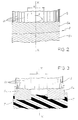
  • Fig. 4 is a diagrammatic and qualitative representation of a preferential example for distribution of the zero-degree cords along the axial extension l of the belt structure depending on the variable distance from the rotation axis r-r of the tyre.
A high-transverse-curvature tyre for equipment of two-wheeled vehicles, particularly suitable for mounting to the front wheel of a motor-cycle, is identified by 1 in fig. 1.
It is known that, in order to be able to have a good directional stability and control of a vehicle, the front tyre must have a reduced sectional width, which gives rise to the requirement of a strong transverse curvature in the tread, said strong transverse curvature being the cause of the difficulties set forth in the introductory part of the present invention.
The degree of this transverse curvature is defined by the particular ratio value between the distance ht (measured along the equatorial plane X-X) of the tread crown from the line b-b passing by the tread extremities C and the distance wt between said extremities.
If the tread extremities cannot be easily identified, for example due to lack of a precise reference such as the corner denoted by C in Fig. 1 for example, distance wt will be considered the measurement of the maximum chord of the tyre.
As already disclosed, this ratio is referred to as curvature ratio or, preferably, "tread camber".
This value in front tyres for two-wheeled vehicles is greater than 0.2 and always higher than the value of the corresponding rear tyre having a camber included between 0.15 and 0.30.
On the other hand, the invention is not limited to tyres for front wheels, but can efficiently and conveniently also apply to tyres for rear wheels.
Tyre 1 comprises a carcass provided with a reinforcing structure formed of at least one ply 2 of rubberized fabric, preferably but not exclusively of the radial type, the end flaps 3 of which are folded back around anchoring bead cores 4.
Between the sidewalls of the carcass ply 2 and the folded-back flaps 3 fillers 5 are provided which are made of an elastomeric material and are disposed on the radially external surface of said bead cores 4.
It is known that the tyre area comprising the bead core 4 and fillers 5 forms the tyre bead intended for anchoring of the tyre to a corresponding mounting rim, not shown.
Crown-wise to the carcass, tyre 1 comprises a belt structure 6 consisting of at least one radially external layer 9 and one radially internal layer 8 both comprised of structure reinforcing elements.
More particularly, the reinforcing elements of the radially external layer are cords 10 wound up around the carcass in a circumferential direction, usually called "at zero degrees" with reference to its lying relative to the equatorial plane of the tyre.
The reinforcing elements of the radially internal layer can be individual threads/wires or cords of any appropriate material, in any case always oriented in a crossed direction to the equatorial plane, or reinforcing fillings such as fibrous fillings for example, disposed randomly but preferably oriented according to a preferential direction too, and crossed relative to the equatorial plane.
In the following of the present description reference will be always made to cords, but it is pointed out that by this term also individual elementary threads/wires or untwisted yarns are meant, when the text allows this interpretation.
Finally, a tread band 11 is disposed in known manner on the belt 6. Said tread band is provided with a tread pattern and is intended as the ground-contacting area of the tyre.
Said radially external layer is formed of a plurality of distinct cords or at least one cord or one ribbon of few (preferably 2 to 5) cords wound up spiral-wise on the crown portion of the carcass according to a given pitch which is preferably variable and at all events has a variable thickness increasing from the centre to the belt extremities.
In spite of the fact that spiralling by itself and the pitch variability involve a winding angle different from zero, this angle has always such a low value that it can substantially be considered as equal to zero degrees.
It is further pointed out that a constant winding pitch along the perimetric extension l of the belt, by effect of the carcass curvature, gives rise in any case to a variable thickness in an axial direction.
In a convenient embodiment said cords 10 are the well-known high elongation (HE) metallic cords the use and features of which have already been widely described in the Italian Patent Application No. 20646 A/90 for example, in the name of the same Applicant.
In greater detail, these cords consist of a given number of strands (1 to 5, and preferably between 3 and 4), each strand being formed of a given number of individual wires, (2 to 10 and preferably between 4 and 7), each of a diameter greater than 0.10 mm, preferably included between 0.12 and 0.35 mm. The wires in the strands and the strands in the cord are helically wound together in the same direction, according to the same winding pitches or to different winding pitches for the wires and the strands.
Preferably said cords are made of high-carbon (HT) steel wires, that is wires containing carbon in an amount greater than 0.9%. In particular, in a specific prototype prepared by the Applicant, the helical winding of layer 9 consisted of a single cord 10, known as 3x4x0.20 HE HT cord spiralled from one extremity of the belt to the other: said quotation identifies a metal cord formed of 3 strands each consisting of four elementary wires wound in the same direction as the strands and of a diameter corresponding to 0.20 mm; as is known the abbreviation HE means "high elongation" and the abbreviation HT means "high tensile" steel.
These cords have an ultimate elongation included between 4% and 8% and a typical well-known behaviour to tensile stress, the so-called "spring behaviour".
Due to this behaviour, which on the other hand is desired, it is of the greatest importance to control the pre-loading condition of the zero-degree winding in the raw tyre, before vulcanization.
This can be carried out to advantage, for example, by winding the cord or cords giving it/them a given tension around the radially internal layer previously disposed on the manufacturing drum: it is apparent that only a layer having sufficient mechanical strength can withstand winding of a tensioned cord without being torn, as discussed in the following.
As regards the different techniques of spiralling the cords about the carcass, they are well-known too and are not part of the invention and therefore are not illustrated herein.
Obviously, the preferential use of the metallic cords does not exclude the use of other cords, to the ends of the present invention; in particular, the well-known textile cords made of aramidic fibre and commercially known as Kevlar (trademark by DuPont) can be also employed.
In accordance with the present invention the distribution thickness of the cord 10 coils progressively varies along the layer from the equatorial plane towards the extremities, preferably following a predetermined relation.
In a particularly convenient embodiment, based on said relation it is provided that the product of the mass of the cord coils disposed in a unitary portion of given value by the square of the distance between the centre of said portion and the rotation axis r-r of the tyre should keep a substantially constant value over the whole axial extension of the belt in such a manner that during the tyre rotation the resulting centrifugal forces in each of said portions have all the same value thereby giving rise to a given uniform stress condition from one extremity of the belt to the other one.
Conveniently, as simply and diagrammatically shown in Fig. 4, showing by l the curvature outline of the lower layer 8, the axial thickness according to which the cord coils are distributed, appears to be given by the following relation: Nx = K R2 r2 No wherein:
  • No is the number of cord coils disposed in a central portion of unitary value, 1 cm for example, on either side of the equatorial plane;
  • R is the distance between the centre of said central portion in the radially outermost layer and the rotation axis of the tyre;
  • r is the distance between che centre of one of said unitary portions located in the region included between the centre and the extremities of the radially outermost layer, and the rotation axis of the tyre;
  • K is a parameter taking into account the constituent material and the cord formation, as well as the rubber amount around the cord and the weight of the section of the radially-internal layer at said unitary portion, which is variable with the occurrence of variations in the material type and structural features of the belt strips along the crown outline that diverge from the reference values.
This parameter will take a value substantially close to 1 in the case in which the cords have the same formation and all the connected materials are the same over the whole extension of the layers, and different values in connection with variations in the materials and the formation of the reinforcing elements along the perimetric extension of the belt.
By way of example only, it is possible to suppose one layer of zero-degree cords comprising textile (aramid) cords at a central position and metallic (HE) cords at the adiacent side sections, and vice versa.
Still by way of example, it is described the zero-degree cord layer made by the Applicant for the prototype tyre used for carrying out comparative tests, illustrated in the following, with known tyres of the prior art.
A steel HE HT 3x4x0.20 cord is selected the ultimate-elongation value of which is equal to 6% and which is rubberized in the usual manner, and a ribbon consisting of three side-by-side cords is formed in advance and spiralled around the carcass with an axial winding pitch of 7 mm and a tension of 400 grams and more.
A 100 m length of this band is 1.800 kg in weight; the band coil along the equatorial plane X-X of radius R = 290 mm is 0.27 kg in weight.
Based on an evaluation criterion depending on the desired features (comfort, mechanical strength, stiffness) a value of 4 cords/cm was selected (see Fig. 4) as the number of coils No included within the portion To, located on either side of the equatorial plane, of a unitary length of 1 cm; the overall weight of the cord coils in said portion was 0.36 kg.
The product of this overall weight by the square of R identifies the constant value V designed to control the coil number and/or thickness and/or the cord type in any other unitary portion included between the equatorial plane X-X and the belt extremities.
For example, with reference to Fig. 4, considering the unitary portion T of radius r, it came out that the number Nx of coils of said cord in such a portion resulted from the following expression: V = r2 Pr wherein Pr is the coil weight in portion T.
Clearly, the previously reproduced expressions only constitute a guide for selection of the optimal values, since generally values resulting from formulae (being variable in a continuous manner) do not coincide with the actually usable values which by their own nature vary in a discontinuous manner.
In other words, for a theoretical value of 3.64 cords/cm selection should be made between 3 and 4 cords/cm, or between 36 or 37 cords/dm at most, since the use of fractionary values is impossible.
Practically, from the preceding expression the following values were determined: the optimal number Nx of coils necessary for each portion; the resulting thickness of same along the peripheral belt extension, which was caused to vary from 4 to 7 cords/cm; and the resulting band-winding pitch, which was caused to vary from 7 to 5 mm, from the equatorial plane to the extremities.
As regards thickness of said cords at zero degrees in the area located on either side of the equatorial plane where the maximum thinning out takes place, it does not exceed 8 and preferably is included between 4 and 6 cords/cm.
Taking now into account the radially inner layer, several alternative embodiments are possible from which a person of ordinary skill in the art will be able to select the one more appropriate to the specific requirements.
First of all the layer may comprise two strips 8a, 8b of rubberized fabric consisting of reinforcing elements incorporated into an elastomeric matrix, oriented according to preferential directions crossing each other in the two strips and preferably symmetrically inclined to the equatorial plane X-X, substantially in the same manner as the traditional belt of the prior art.
The important difference from the prior art belt resides in the more reduced stiffness of the new belt at a wide area a (included between 10% and 30% of the axial extension of the belt) on either side of the equatorial plane; this more reduced stiffness can be conveniently achieved by acting either on the thickness of the reinforcing elements, or on the constituent material, or on the orientation of said elements to the equatorial plane, or on any other combination of the above expedients. This stiffness value can be expressed in different ways, for example by the thickness of said reinforcing elements (any other condition being equal), but more generally it is expressed by the modulus of elasticity or ultimate tensile stress of said radially internal belt layer, measured in the circumferential direction of the tyre; said layer preferably will have a stiffness that does not exceed 65% of the stiffness of the equivalent belts in the known art.
In particular, the material, structure and lying angles being equal, the overall thickness of the reinforcing elements crossing a right section of unitary width, on either side of the equatorial plane, in an oblique direction relative to said plane (as shown in Fig. 2) does not exceed, and preferably is lower than the usual thickness of the elements of said traditional belt, which is, as known, in the order of 14 cords/cm.
The angles formed by said cords relative to the equatorial plane are included between 18° and 50° and preferably between 22° and 45°.
According to a convenient alternative version, said strips are even interrupted at the equatorial plane, giving rise to an area a of a width included between 10% and 30% of the axial extension of said belt, in which only circumferentially-directed reinforcing cords 10 are present. The end edges of said strips are in a stepped relationship, as currently occurs in the art.
The above described version has the advantage that appropriate thickness values can be selected in said strips for the side portions of the belt structure without correspondingly thickening the central crown portion of the belt structure.
In particular, it was found that for nylon (title 940/2) cords, thickness values included between 4 and 8 cords/cm were appropriate in combination with orientation angles relative to the radial direction included between 30° and 50°.
In a convenient manner, the reinforcing elements of said strips are monofilaments and/or twisted or untwisted yarns, and their cords are made either of varied textile materials, for example natural fibres such as rayon or cotton, or of synthetic fibres such as polyamide, nylon and aramid, or even of metal.
In a particular preferential embodiment, both strips comprise cords of the same material, whereas in another embodiment the cords of one strip are of a different material from those of the other strip, nylon-aramid or aramid-metal couplings being for example selected; in this case the angles of said cords included within the above described range are preferably different from each other and not symmetric.
In an alternative solution the radially internal layer is formed of only two strips, disposed axially side by side along the perimetric outline, provided each (8c, 8d) with reinforcing elements oriented in a crossed direction inclined to the equatorial plane, so that the two strips give rise to a substantially herringbone configuration of the reinforcing elements. In this case too, the two side-by-side strips can be maintained close to each other or also joined along their facing longitudinal edges, or completely separated. In this case it is useful for the facing edges to keep the same axial width as pointed out above in the case of the superposed strips.
The previous remarks in connection with the constituent material, orientation and thickness of the reinforcing elements of said two strips also apply to the case of the individual strips as described just above.
In a further advantageous embodiment of the invention, said radially internal layer consists of a sheet 7 of elastomeric material, which is axially continuous or interrupted at the plane X-X, as already described, charged with a reinforcing filling consisting of short discontinuous fibres, optionally randomly dispersed within the elastomeric matrix but preferably substantially oriented in an axial direction or a direction inclined to the equatorial plane X-X of the tyre, symmetric with the direction of the adjacent sheet portion.
In this case one can no longer speak of fibre thickness, but one must take into account their distribution density per unit of volume:
this density is preferably included between 0.5% and 5% of the overall volume.
Conveniently, said fibrous reinforcing fillings are of a material selected from the group consisting of textile, metallic or glass fibres. In particular the use of short fibres formed with fibrils of aramid, better known as "aramid pulp" or "Kevlar-pulp" have proved to be convenient.
Manufacturing of the carcass bead cores using an aramidic fibre has also proved to be convenient; the resulting structure has advantageously caused an improved flexibility of the tyre beads facilitating fitting of the tyre onto the rim, which fitting is made more difficult by the greater stiffness of the side sections of the tread, which on the other hand are sought-after and conveniently achieved in the tyre and by the process of the invention.
In order to evalutate the qualitative results achieved by the tyres of the invention, a series of road and track tests were carried out, and the tyre of the invention was compared with equivalent tyres, i.e. approved for the same type of operation and vehicle, of the best brands available on the market.
These tyres were two tyres of usual production manufactured by the Applicant and the tyre of a different manufacturer, considered as the best of the competitors' tyres, under normal-drive and top-limit-drive conditions, respectively.
The features of the used vehicle are as follows:
MOTOR-CYCLE HONDA CBR 1000
Front tyre size 120/70 ZR 17
· Inflation pressure 2.5 bar
· Rim 3.50 - 17
Rear tyre size 170/60 ZR 17
· Inflation pressure 2.9 bar
· Rim 5.50 - 17
The road test consisted in evaluating the qualitative level of the most important behavioural drive features especially depending on the belt structure, giving a subjective judgement, converted to a score variable from 1 to 7, awarding the maximum score to the tyre showing the best behaviour in each of the considered features.
It should be noted that the effects of the individual structural features of the different compared tyres which differ from each other by more than one feature are not evaluated separately, but it is analyzed only the overall behaviour of the tyre influenced by all the features of the finished product, even if mainly affected by the belt structure type.
On the other hand, the test exactly aimed at evaluating the overall effect of the invention in comparison with the best equivalent tyres available on the market.
At all events, the tyre of the invention had a radial two-ply carcass with nylon (title 940/2) cords, two radially-superposed belt strips provided with nylon (title 940/2) cords, symmetrically crossed with each other in the two strips, distributed according to a thickness of 6 cords/cm and inclined to an angle of 40° relative to the equatorial plane, which values were measured at the crown.
The radially external layer was made of metallic HE cords and consisted of a band winding as previously described.
On the contrary, the comparative tyres substantially identical with each other had a radial two-ply carcass made of nylon (title 940/2), and only a pair of radially-superposed belt strips, provided with cords made of aramid (title 1100/2), symmetrically crossed with each other in the two strips, distributed according to a thickness of 9 cords/cm and inclined to an angle of 23° relative to the equatorial plane, according to the known art, which values were all measured at the tyre crown.
In the following table the result of the comparison between the tyre of the invention and said known tyres is reproduced.
TEST/TIRES A B C D
SENSITIVITY TO SHIMMY 7 6 5.5 6
DRIVE BEHAVIOUR 6.5 6.5 7 6.7
SHOCK-ABSORBING CAPABILITY 7 6 6 6.5
DIRECTIONAL STABILITY 6.5 6.5 7 6.5
BRAKING BEHAVIOUR 7 5 6 6
COMFORT 7 5 6 6
Tyres are identified as follows:
  • A - TYRE OF THE INVENTION
  • B - COMPETITION TYRE
  • C - TYRE MTR 01 by PIRELLI (Normal production)
  • D - TYRE MEZ 2 by METZELER (Normal production)
  • One can see that the tyre of the invention has a better performance level taken as a whole than the competitors' one, in particular a better level not only as regards the absorption capability of the road-bed unevennesses, corresponding to expectations, but also and surprisingly, as regards the braking behaviour, that is roadholding and braking distance.
    The invention achieves all the intended purposes.
    As regards the working process, the reinforcing layer at a position radially internal to the zero-degree cord layer, in particular at the side areas of the tread, of a rapidly decreasing diameter, constitutes a support element of appropriate consistence and mechanical strength, capable of enabling winding of the cord or cords at zero degrees on the manufacturing drum even under a tension of non-negligible value, in order to control the pre-loading condition of the winding in the raw tyre.
    As regards the tyre behaviour on the road, the combination of a zero-degree winding with a more internal reinforcing layer, in a single or double strip, optionally interrupted at the central tread section, enables the two and conflicting requirements of a high flexibility of the belt under running conditions on a straight stretch and high stiffness for withstanding slip thrusts during a running on a bend, to be balanced.
    In particular, by acting on thickness values of the reinforcing elements taken as a whole and on the lying angles of the reinforcing elements in the lower layer, differentiated thickness values of the belt from one area to another can be determined, so as to give an improved roadholding to the tyre and simultaneously a high comfort level to the driver.
    It was also unexpectedly found that the greater capability of deformation of the belt, allowed by the presence of a layer having zero-degree reinforcing elements and a graduation of the thickness value of the elements in an axial direction, enables the achievement of a ground-contacting area in the tyre that increases on braking, which results in a lower braking distance required by the vehicle, so that safety on driving is increased.
    The evenness of the stress state to which the tyre as a whole and in particular the radially-external belt layer is subjected under highspeed conditions is finally emphasized.
    In fact, as described, by controlling the axial distribution of the zero-degree cords by means of the previously indicated relation fixing the number of the cord coils disposed in one portion of unitary value depending on the localized belt diameter, it is possible to submit at least the crown portion of the tyre to a constant stress, under the effect of the centrifugal force, both at the tread centre and at the extremities, where the effect of the diameter reduction is more considerable.
    Therefore the absence of stresses of high value localized at some points rather than others takes place over the whole belt, which will bring about an improvement in the tyre service life.
    It is apparent that the present description only has an explanatory and not restrictive function and therefore all modifications and variations not expressly illustrated but that can be easily deduced by a person of ordinary skill in the art must be considered within the scope of the present invention as defined in the appended claims.
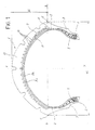
    Claims (4)

    1. A tyre for two-wheeled vehicles comprising a carcass of toric form having a high transverse curvature and provided with a central crown and two sidewalls terminating in a pair of beads for anchoring to a corresponding mounting rim, a tread band located on said crown and having a curvature ratio at least as high as 0.3 and a circumferentially-inextensible belt structure disposed between said carcass and tread band, characterized in that said belt structure at a radially external position is comprised of a layer of cord coils substantially disposed at a zero angle to the equatorial plane of the tyre.
    2. A tyre for two-wheeled vehicles comprising a carcass of toric form having a high transverse curvature and provided with a central crown and two sidewalls terminating in a pair of beads for anchoring to a corresponding mounting rim, a tread band located on said crown and a circumferentially-inextensible belt structure disposed between said carcass and tread band, which belt comprises a radially external layer provided with a plurality of cord coils disposed at a substantially zero angle to the equatorial plane of the tyre, in axial side-by-side relationship and extended from one extremity to the other extremity of said belt, and at least one radially internal layer provided with reinforcing elements oriented in a crossed direction relative to the equatorial plane of the tyre, characterized in that said tyre has a curvature ratio or tread camber at least as high as 0.3.
    3. A tyre for two-wheeled vehicles comprising a carcass of toric form having a high transverse curvature and provided with a central crown and two sidewalls terminating in a pair of beads for anchoring to a corresponding mounting rim, a tread band located on said crown and a circumferentially-inextensible belt structure disposed between said carcass and tread band, which belt comprises a radially external layer provided with a plurality of cord coils disposed at a substantially zero angle to the equatorial plane of the tyre, in axial side-by-side relationship and extended from one extremity to the other extremity of said belt, and at least one radially internal layer provided with reinforcing elements oriented in a crossed direction relative to the equatorial plane of the tyre, characterized in that the thickness according to which said cord coils at an angle of zero degrees are distributed along the axial extension of said belt is given by the following relation: Nx = K R2 r2 No wherein:
      No is the number of cord coils disposed in a central portion of unitary length located on either side of the equatorial plane;
      R is the distance between the centre of said portion and the rotation axis of the tyre;
      r is the distance between the centre of the generic unitary portion included between the equatorial plane and the extremities of said radially external layer, and the rotation axis of the tyre;
      K is a parameter taking into account the constituent material and the cord formation, as well as the amount of rubber around the cord and the weight of the radially-internal layer section at said unitary portion which is variable with the occurrence of variations in the material type and structural features of the belt strips along the crown profile that diverge from the reference values.
    4. A tyre for two-wheeled vehicles comprising a carcass of toric form having a high transverse curvature and provided with a central crown and two sidewalls terminating in a pair of beads for anchoring to a corresponding mounting rim, a tread band located on said crown and a circumferentially-inextensible belt structure disposed between said carcass and tread band, which belt comprises a radially external layer provided with a plurality of cord coils disposed at a substantially zero angle to the equatorial plane of the tyre, in axial side-by-side relationship and extended from one extremity to the other extremity of said belt, and at least one radially internal layer provided with reinforcing elements oriented in a crossed direction relative to the equatorial plane of the tyre, characterized in that:
      said tread band has a curvature ratio at least as high as 0.3,
      the thickness of said cord coils increasingly grows from the equatorial plane to the belt extremities;
      the thickness of said cord coils, in a right section of unitary width located on either side of the equatorial plane does not exceed 6 cords/cm.
    EP01109906A 1995-08-01 1996-07-23 High-transverse-curvature tyre, in particular for a two-wheeled vehicle Withdrawn EP1127714A3 (en)

    Applications Claiming Priority (3)

    Application Number Priority Date Filing Date Title
    ITMI951681 1995-08-01
    IT95MI001681A IT1277400B1 (en) 1995-08-01 1995-08-01 TIRE WITH HIGH TRANSVERSAL CURVATURE PARTICULARLY FOR TWO WHEEL VEHICLES
    EP96111804A EP0756949B1 (en) 1995-08-01 1996-07-23 High-transverse-curvature tyre, in particular for a two-wheeled vehicle

    Related Parent Applications (1)

    Application Number Title Priority Date Filing Date
    EP96111804A Division EP0756949B1 (en) 1995-08-01 1996-07-23 High-transverse-curvature tyre, in particular for a two-wheeled vehicle

    Publications (2)

    Publication Number Publication Date
    EP1127714A2 true EP1127714A2 (en) 2001-08-29
    EP1127714A3 EP1127714A3 (en) 2003-07-02

    Family

    ID=11372100

    Family Applications (2)

    Application Number Title Priority Date Filing Date
    EP96111804A Expired - Lifetime EP0756949B1 (en) 1995-08-01 1996-07-23 High-transverse-curvature tyre, in particular for a two-wheeled vehicle
    EP01109906A Withdrawn EP1127714A3 (en) 1995-08-01 1996-07-23 High-transverse-curvature tyre, in particular for a two-wheeled vehicle

    Family Applications Before (1)

    Application Number Title Priority Date Filing Date
    EP96111804A Expired - Lifetime EP0756949B1 (en) 1995-08-01 1996-07-23 High-transverse-curvature tyre, in particular for a two-wheeled vehicle

    Country Status (11)

    Country Link
    US (3) US5902425A (en)
    EP (2) EP0756949B1 (en)
    JP (1) JP4107689B2 (en)
    KR (1) KR100428036B1 (en)
    AR (1) AR003153A1 (en)
    AT (1) ATE208713T1 (en)
    BR (1) BR9604055A (en)
    DE (1) DE69616894T2 (en)
    ES (1) ES2168415T3 (en)
    IT (1) IT1277400B1 (en)
    TR (1) TR199600630A1 (en)

    Cited By (2)

    * Cited by examiner, † Cited by third party
    Publication number Priority date Publication date Assignee Title
    EP1531063A1 (en) * 2003-11-14 2005-05-18 The Goodyear Tire & Rubber Company Pneumatic tire
    WO2006090418A1 (en) * 2005-02-28 2006-08-31 Pirelli Tyre S.P.A. Method and apparatus for manufacturing pneumatic tyres for vehicule wheels

    Families Citing this family (44)

    * Cited by examiner, † Cited by third party
    Publication number Priority date Publication date Assignee Title
    IT1277400B1 (en) * 1995-08-01 1997-11-10 Pirelli TIRE WITH HIGH TRANSVERSAL CURVATURE PARTICULARLY FOR TWO WHEEL VEHICLES
    IT1283051B1 (en) 1996-05-22 1998-04-07 Pirelli PAIR OF HIGH TRANSVERSAL CURVATURE TIRES, ESPECIALLY FOR TWO-WHEELED VEHICLES AND METHOD FOR BEHAVIORAL CONTROL
    IT1283350B1 (en) * 1996-07-29 1998-04-17 Pirelli TIRE WITH HIGH TRANSVERSAL CURVATURE IN PARTICULAR FOR REAR WHEELS OF MOTOR VEHICLES
    IT1283351B1 (en) * 1996-07-29 1998-04-17 Pirelli TIRE WITH HIGH TRANSVERSAL CURVATURE IN PARTICULAR FOR FRONT WHEELS
    JP3782875B2 (en) * 1997-09-30 2006-06-07 横浜ゴム株式会社 Pneumatic radial tire
    US6412533B1 (en) 1997-12-29 2002-07-02 Pirelli Pneumatici S.P.A. High transverse-curvature tire for two-wheeled vehicles including specified belt structure
    EP0928703A1 (en) * 1997-12-29 1999-07-14 PIRELLI PNEUMATICI S.p.A. High transverse curvature tire for two-wheeled vehicles and method for its manufacture
    US6397911B1 (en) 1997-12-29 2002-06-04 Pirelli Pneumatici S.P.A. High transverse-curvature motor-bike tire
    EP0928704B1 (en) * 1997-12-29 2004-04-14 PIRELLI PNEUMATICI S.p.A. High transverse curvature tyre for two-wheeled vehicles
    US6244315B1 (en) 1998-04-16 2001-06-12 Pirelli Pneumatici S.P.A. Tyre with high transverse curvature coefficient in particular for a two-wheeled vehicle
    EP0950546B1 (en) * 1998-04-16 2004-10-13 PIRELLI PNEUMATICI S.p.A. Tyres with high tranverse curvature coefficient, in particular for a two-wheeled vehicle
    EP1541378A1 (en) * 1998-11-26 2005-06-15 Bridgestone Corporation Pneumatic tire front wheel of motorcycle
    FR2800325B1 (en) * 1999-11-03 2002-10-11 Dunlop Sa MOTORCYCLE TIRE
    US6651716B1 (en) * 2000-02-23 2003-11-25 The Goodyear Tire & Rubber Company Method and tire adapted for post cure tire uniformity correction
    JP2001301422A (en) 2000-04-25 2001-10-31 Bridgestone Corp Installation structure for pneumatic tire
    US20050269005A1 (en) * 2000-09-20 2005-12-08 Steinke Richard A Air no air elastomeric tire
    BR0116584B1 (en) * 2000-12-27 2010-06-01 vehicle wheel tire, pair of two-wheel vehicle tires, motor vehicle fitted with a pair of tires and methods for rubbering metal reinforcement ropes for vehicle wheel tires and for laying at least one metal reinforcement cord over the tire drum for vehicle wheels.
    US7404425B2 (en) * 2002-04-24 2008-07-29 The Goodyear Tire & Rubber Company Belt package for super single truck tires
    AU2003240615A1 (en) * 2002-05-10 2003-11-11 Michelin Recherche Et Techniques S.A. Two-wheeler tyre
    JP4381982B2 (en) * 2002-08-09 2009-12-09 ソシエテ ド テクノロジー ミシュラン Tires for vehicles with two wheels
    EP1615782A1 (en) * 2003-03-26 2006-01-18 Pirelli Pneumatici Societa' Per Azioni Pneumatic tyre for two wheeled vehicles
    AU2003246563A1 (en) * 2003-06-19 2005-01-21 Pirelli Pneumatici S.P.A. Tyre with improved belt structure
    GB2404636B (en) * 2003-08-01 2006-12-20 Dunlop Tyres Ltd Motorcycle radial tyre
    JP4533181B2 (en) 2005-02-21 2010-09-01 株式会社ブリヂストン Pneumatic tires for motorcycles
    KR100578101B1 (en) * 2005-03-29 2006-05-10 금호타이어 주식회사 Pneumatic Tires for High Speed Driving
    FR2885846B1 (en) * 2005-05-18 2007-07-06 Michelin Soc Tech PNEUMATIC FOR TWO WHEELS
    US8505601B2 (en) * 2005-05-31 2013-08-13 The Yokohama Rubber Co., Ltd. Pneumatic radial tire
    FR2897557B1 (en) * 2006-02-21 2008-04-18 Michelin Soc Tech PNEUMATIC FOR VEHICLES
    JP5013522B2 (en) * 2007-09-07 2012-08-29 株式会社ブリヂストン Pneumatic radial tire
    FR2939723B1 (en) * 2008-12-17 2010-12-31 Michelin Soc Tech PNEUMATIC VEHICLE COMPRISING A LAYER OF CIRCUMFERENTIAL REINFORCING ELEMENTS
    FR2939719B1 (en) 2008-12-17 2010-12-31 Michelin Soc Tech PNEUMATIC VEHICLE COMPRISING A BEARING BELT CONSISTING OF MULTIPLE MIXTURES AND A LAYER OF CIRCUMFERENTIAL REINFORCING ELEMENTS WITH NOT VARIABLE
    JP4659099B2 (en) * 2009-02-16 2011-03-30 住友ゴム工業株式会社 Motorcycle tire and manufacturing method thereof
    EP2459392B1 (en) * 2009-07-30 2013-07-03 Pirelli Tyre S.P.A. Tire for a motorcycle and method for controlling a motorcycle
    JP5342366B2 (en) * 2009-08-05 2013-11-13 株式会社ブリヂストン Pneumatic tire
    FR2956355B1 (en) * 2010-02-12 2012-05-18 Michelin Soc Tech TIRE FOR TWO - WHEELED VEHICLES COMPRISING A BEARING BAND HAVING INCISIONS.
    CN102390225B (en) * 2011-10-24 2013-06-12 厦门正新橡胶工业有限公司 Low-aspect-ratio motorcycle tire
    JP6043065B2 (en) * 2012-01-10 2016-12-14 住友ゴム工業株式会社 Method for manufacturing motorcycle tire
    JP6111204B2 (en) * 2012-02-06 2017-04-05 株式会社ブリヂストン Pneumatic radial tire
    CN105682939B (en) * 2013-10-29 2018-10-19 株式会社普利司通 tire
    JP5918742B2 (en) 2013-12-03 2016-05-18 住友ゴム工業株式会社 Manufacturing method of pneumatic tire for motorcycle
    EP3312023B1 (en) 2016-08-30 2019-10-09 Sumitomo Rubber Industries, Ltd. Motorcycle tire
    WO2018207068A1 (en) * 2017-05-08 2018-11-15 Pirelli Tyre S.P.A. Tyre for bicycle wheels
    JP7467964B2 (en) 2019-03-22 2024-04-16 住友ゴム工業株式会社 Motorcycle tires
    JP7268434B2 (en) 2019-03-22 2023-05-08 住友ゴム工業株式会社 motorcycle tire

    Family Cites Families (20)

    * Cited by examiner, † Cited by third party
    Publication number Priority date Publication date Assignee Title
    GB1438288A (en) * 1972-09-01 1976-06-03
    IT1081053B (en) * 1976-05-17 1985-05-16 Pirelli IMPROVEMENT OF THE RESISTANT STRUCTURE OF TIRES FOR VEHICLE WHEELS
    IT1093433B (en) * 1978-03-09 1985-07-19 Pirelli IMPROVEMENT OF THE ANNULAR STRUCTURE OF REINFORCEMENT FOR RADIAL TIRES
    JPS5671604A (en) * 1979-11-16 1981-06-15 Ohtsu Tire & Rubber Co Ltd Radial tire
    DE3410857C2 (en) * 1984-03-23 1993-11-04 Metzeler Gmbh BELT TIRES
    DE3606934A1 (en) * 1986-03-04 1987-09-10 Continental Gummi Werke Ag VEHICLE TIRES
    EP0524703B1 (en) * 1987-06-18 1996-08-21 Sumitomo Rubber Industries Limited Apparatus for forming a band of a radial tyre
    US4871004A (en) * 1988-02-17 1989-10-03 The Goodyear Tire & Rubber Company Rubber containing aramid pulp reinforcement
    GB8813776D0 (en) * 1988-06-10 1988-07-13 Sumitomo Rubber Ind Motor cycle radial tyre
    IT1236885B (en) * 1989-12-19 1993-04-26 Pirelli PROCEDURE FOR THE MANUFACTURE OF TIRES WITH A TORIC PROFILE WITH A HIGH CROSS CURVATURE, APPARATUS FOR ITS IMPLEMENTATION AND PRODUCT OBTAINED
    JP2842558B2 (en) * 1990-05-02 1999-01-06 住友ゴム工業 株式会社 Radial tires for motorcycles
    IT1248851B (en) * 1990-06-14 1995-01-30 Pirelli PROCEDURE FOR THE MANUFACTURE OF TIRES FOR TWO-WHEEL AND TIRE VEHICLES SO PRODUCED
    ES2075426T3 (en) 1991-01-07 1995-10-01 Michelin & Cie MOTORCYCLE TIRES.
    JP3083862B2 (en) * 1991-03-05 2000-09-04 株式会社ブリヂストン Pneumatic tires for motorcycles
    JP3142920B2 (en) * 1991-11-06 2001-03-07 株式会社ブリヂストン Pneumatic radial tires for motorcycles
    AT399130B (en) * 1992-03-18 1995-03-27 Hoerbiger Fluidtechnik Gmbh ARRANGEMENT FOR HYDRAULICALLY OPERATING A VEHICLE TOP
    DE69301366T2 (en) 1992-04-06 1996-05-30 Sumitomo Rubber Ind Motorcycle tires
    JP2799322B2 (en) * 1993-06-07 1998-09-17 住友ゴム工業株式会社 Pneumatic tires for motorcycles
    GB2283215B (en) * 1993-10-29 1997-07-23 Sumitomo Rubber Ind Motor-cycle radial tyre
    IT1277400B1 (en) * 1995-08-01 1997-11-10 Pirelli TIRE WITH HIGH TRANSVERSAL CURVATURE PARTICULARLY FOR TWO WHEEL VEHICLES

    Cited By (4)

    * Cited by examiner, † Cited by third party
    Publication number Priority date Publication date Assignee Title
    EP1531063A1 (en) * 2003-11-14 2005-05-18 The Goodyear Tire & Rubber Company Pneumatic tire
    US7086440B2 (en) 2003-11-14 2006-08-08 The Goodyear Tire & Rubber Company Pneumatic tire with annular reinforcing strip layer
    US7900672B2 (en) 2003-11-14 2011-03-08 The Goodyear Tire & Rubber Company Pneumatic tire with annular reinforcing strip layer
    WO2006090418A1 (en) * 2005-02-28 2006-08-31 Pirelli Tyre S.P.A. Method and apparatus for manufacturing pneumatic tyres for vehicule wheels

    Also Published As

    Publication number Publication date
    US20030155056A1 (en) 2003-08-21
    DE69616894T2 (en) 2002-08-29
    TR199600630A1 (en) 1997-02-21
    AR003153A1 (en) 1998-07-08
    EP0756949A1 (en) 1997-02-05
    ITMI951681A0 (en) 1995-08-01
    ITMI951681A1 (en) 1997-02-01
    IT1277400B1 (en) 1997-11-10
    DE69616894D1 (en) 2001-12-20
    US6530408B1 (en) 2003-03-11
    ATE208713T1 (en) 2001-11-15
    KR100428036B1 (en) 2004-07-19
    US5902425A (en) 1999-05-11
    KR970010146A (en) 1997-03-27
    JP4107689B2 (en) 2008-06-25
    EP0756949B1 (en) 2001-11-14
    JPH09118109A (en) 1997-05-06
    BR9604055A (en) 1998-06-16
    EP1127714A3 (en) 2003-07-02
    ES2168415T3 (en) 2002-06-16

    Similar Documents

    Publication Publication Date Title
    EP0756949B1 (en) High-transverse-curvature tyre, in particular for a two-wheeled vehicle
    EP0808730B1 (en) Pair of high-transverse-curvature tyres for two-wheeled vehicles
    US6755227B2 (en) High-transverse-curvature tire, in particular for use in front wheels of motor-vehicles
    KR100637852B1 (en) High lateral curvature tires for two-wheeled vehicles
    KR100572048B1 (en) Tires, especially for two-wheeled vehicles, with high lateral curvature coefficients
    US6397911B1 (en) High transverse-curvature motor-bike tire
    JP4650917B2 (en) Pneumatic tire
    JP4548925B2 (en) Pneumatic tire
    JP2733428B2 (en) Pneumatic tire
    US6244315B1 (en) Tyre with high transverse curvature coefficient in particular for a two-wheeled vehicle
    JPH11245616A (en) Two-wheeler tire large in crossing curvature and manufacture thereof
    JPH1111107A (en) Pneumatic radial tire for passenger car
    JP2005507338A (en) Tires for automotive wheels with an improved bead structure
    CN1208701A (en) Pair of high-transverse-curvature tyres, in particular for two-wheeled vehicles, method of controlling behaviour of such vehicles on bend and front tyre of said pair
    JP2892927B2 (en) Pneumatic radial tire
    JPH05270209A (en) Motorcycle tires
    JPH04151305A (en) Radial tire
    HK1019320B (en) Pair of high-transverse-curvature tyres, in particular for two-wheeled vehicles
    JPH11321232A (en) Pneumatic radial tire

    Legal Events

    Date Code Title Description
    PUAI Public reference made under article 153(3) epc to a published international application that has entered the european phase

    Free format text: ORIGINAL CODE: 0009012

    AC Divisional application: reference to earlier application

    Ref document number: 756949

    Country of ref document: EP

    AK Designated contracting states

    Kind code of ref document: A2

    Designated state(s): AT BE CH DE DK ES FI FR GB GR IT LI LU NL PT SE

    PUAL Search report despatched

    Free format text: ORIGINAL CODE: 0009013

    AK Designated contracting states

    Designated state(s): AT BE CH DE DK ES FI FR GB GR IT LI LU NL PT SE

    RIC1 Information provided on ipc code assigned before grant

    Ipc: 7B 60C 9/22 A

    AKX Designation fees paid

    Designated state(s): AT BE CH DE DK ES FI FR GB GR IT LI LU NL PT SE

    STAA Information on the status of an ep patent application or granted ep patent

    Free format text: STATUS: THE APPLICATION IS DEEMED TO BE WITHDRAWN

    18D Application deemed to be withdrawn

    Effective date: 20040103