EP1127625A2 - Sheet coating apparatus - Google Patents
Sheet coating apparatus Download PDFInfo
- Publication number
- EP1127625A2 EP1127625A2 EP00309236A EP00309236A EP1127625A2 EP 1127625 A2 EP1127625 A2 EP 1127625A2 EP 00309236 A EP00309236 A EP 00309236A EP 00309236 A EP00309236 A EP 00309236A EP 1127625 A2 EP1127625 A2 EP 1127625A2
- Authority
- EP
- European Patent Office
- Prior art keywords
- coating
- roller
- sheet
- development
- liquid
- Prior art date
- Legal status (The legal status is an assumption and is not a legal conclusion. Google has not performed a legal analysis and makes no representation as to the accuracy of the status listed.)
- Granted
Links
Images
Classifications
-
- B—PERFORMING OPERATIONS; TRANSPORTING
- B32—LAYERED PRODUCTS
- B32B—LAYERED PRODUCTS, i.e. PRODUCTS BUILT-UP OF STRATA OF FLAT OR NON-FLAT, e.g. CELLULAR OR HONEYCOMB, FORM
- B32B39/00—Layout of apparatus or plants, e.g. modular laminating systems
-
- G—PHYSICS
- G03—PHOTOGRAPHY; CINEMATOGRAPHY; ANALOGOUS TECHNIQUES USING WAVES OTHER THAN OPTICAL WAVES; ELECTROGRAPHY; HOLOGRAPHY
- G03G—ELECTROGRAPHY; ELECTROPHOTOGRAPHY; MAGNETOGRAPHY
- G03G15/00—Apparatus for electrographic processes using a charge pattern
- G03G15/65—Apparatus which relate to the handling of copy material
- G03G15/6555—Handling of sheet copy material taking place in a specific part of the copy material feeding path
- G03G15/6573—Feeding path after the fixing point and up to the discharge tray or the finisher, e.g. special treatment of copy material to compensate for effects from the fixing
-
- G—PHYSICS
- G03—PHOTOGRAPHY; CINEMATOGRAPHY; ANALOGOUS TECHNIQUES USING WAVES OTHER THAN OPTICAL WAVES; ELECTROGRAPHY; HOLOGRAPHY
- G03G—ELECTROGRAPHY; ELECTROPHOTOGRAPHY; MAGNETOGRAPHY
- G03G2215/00—Apparatus for electrophotographic processes
- G03G2215/00362—Apparatus for electrophotographic processes relating to the copy medium handling
- G03G2215/00535—Stable handling of copy medium
- G03G2215/0067—Damping device
-
- Y—GENERAL TAGGING OF NEW TECHNOLOGICAL DEVELOPMENTS; GENERAL TAGGING OF CROSS-SECTIONAL TECHNOLOGIES SPANNING OVER SEVERAL SECTIONS OF THE IPC; TECHNICAL SUBJECTS COVERED BY FORMER USPC CROSS-REFERENCE ART COLLECTIONS [XRACs] AND DIGESTS
- Y10—TECHNICAL SUBJECTS COVERED BY FORMER USPC
- Y10S—TECHNICAL SUBJECTS COVERED BY FORMER USPC CROSS-REFERENCE ART COLLECTIONS [XRACs] AND DIGESTS
- Y10S118/00—Coating apparatus
- Y10S118/01—Anti-offset
Definitions
- the present invention relates to a sheet coating apparatus for applying a predetermined coating liquid onto a sheet.
- a coating apparatus for applying a coating liquid such as wax after a printing operation is proposed.
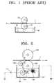
- a conventional coating apparatus as shown in Figure 1, is configured such that a coating roller 10 and a backup roller 20 are rotatably installed along the traveling path through which a sheet 1 passes, and the coating roller 10 is partially immersed in a storage tank 30 containing a liquid wax W. Accordingly, the wax W sticking to the coating roller 10 is coated onto the printed surface of the sheet 1 passing between the coating roller 10 and the backup roller 20.
- the coating roller 10 since there is no means of regulating the amount of wax W moving upward along the surface of the coating roller 10 according to rotation thereof is to be coated onto the sheet 1 the coating roller 10, it is not possible to regulate the amount of coated wax. Thus, the amount of coated wax is nonuniform and excess wax is likely to be coated, which results in increased consumption of a coating liquid. If the content of the coating liquid is reduced, that is, if the content of a liquid carrier which is a solvent contained in the coating liquid, is increased, the amount of the coating liquid consumed can be reduced. However, since the liquid carrier heavily contained in the coating liquid is considerably absorbed into the sheet 1, the image printed on the sheet 1 is likely to blot.
- a sheet coating apparatus including a storage tank in which a coating liquid having charged coating particles dispersed therein is contained, a development roller rotatably installed to be immersed in the coating liquid, a voltage source for applying a voltage to the development roller, a coating roller rotatably installed in a state in which it is partially immersed in the coating liquid while maintaining a predetermined development gap relative to the development roller, and a compression roller for pressing a sheet passing between the same and the coating roller toward the coating roller while securely rotating with respect to the coating roller, wherein the coating particles adhere to the surface of the coating roller at the development gap due to an electric force to then be coated on the sheet passing between the coating roller and the compression roller.
- the apparatus further comprises a squeegee roller rotating in secure contact with the coating roller for compressing the coating particles coated on the coating roller before being coated on the sheet to make the coating particles into a film, for squeegeeing a carrier contained in the film.
- a squeegee roller rotating in secure contact with the coating roller for compressing the coating particles coated on the coating roller before being coated on the sheet to make the coating particles into a film, for squeegeeing a carrier contained in the film.
- the apparatus may further comprise a brush roller rotating in contact with the surface of the coating roller for removing coating particles remaining on the surface of the coating roller after coating the sheet.
- the coating liquid is preferably wax organosol including a powdered wax, a liquid carrier which is a solvent and a charge control agent for charging the wax particles.
- the coating apparatus described in the present invention can be used for coating general sheet-type materials, but the following embodiments relate to the case of a coating liquid being coated on a sheet having an image printed thereon in a printer.
- wax organosol having charged coating particles is used as a coating liquid.
- the coating liquid is a mixture of a powdered wax, a liquid carrier and a charge control agent, and the wax particles are charged by the charge control agent.
- the polarity of the wax particles may be either positive or negative. In the present embodiment, the wax particles are positively charged.
- the coating liquid W' is accommodated in a storage tank 100, as shown in Figure 2.
- a development roller 110 rotating in a state in which it is immersed in the coating liquid W' is provided in the storage tank 100.
- a high voltage of approximately 200 to 600 V is applied from a voltage source 111 to the development roller 110. This is called a development bias voltage.
- a coating roller 120 rotating while maintaining a development gap G of 50 to 200 ⁇ m relative to the development roller 110 is installed in the storage tank 100.
- the lower side of the coating roller 120 is immersed in the coating liquid W' and is kept at the development gap G relative to the development roller 110.
- the upper side of the coating roller 120 is securely pressed against a compression roller 150.
- the coating roller 120 is grounded to 0 volts.
- Reference numeral 130 denotes a squeegee roller securely pressed against the coating roller 120 and rotating. The squeegee roller 130 compresses the wax particles developed on the coating roller 120 to make the same into a film and squeegees the liquid carrier. contained in the film.
- Reference numeral 140 denotes a brush roller for forming a uniform development film during development by removing wax particles adhering to the surface of the coating roller 120 before an area of the surface of the coating roller 120 reaches the development gap G.
- a sheet 1 to be coated passes between the coating roller 120 and the compression roller 150.
- a development bias voltage is applied from the voltage source 111 to the development roller 110. Accordingly, development is carried out at the development gap G by an electric force so that the wax particles are developed on the surface of the coating roller 120.
- the developed wax particles are compressed by the squeegee roller 130 to then be made into a film and then coated on one surface of the sheet 1 passing between the squeegee roller 130 and the compression roller 150 by greater tendency of the wax to adhere to the sheet 1 rather than to the coating roller 120. Thereafter, any wax particles remaining on the coating roller 120 are removed by the brush roller 140 and then the procedure following development is repeated for coating a subsequent sheet.
- wax particles are uniformly distributed by an induced electric force rather than adhering to the surface of the coating roller 120, to then be coated on the sheet 1.
- a uniform coating film can be formed with less coating liquid being consumed than in the conventional case.
- the amount of wax coated on the sheet can be controlled by varying a development bias voltage.
- the sheet coating apparatus can prevent excess coating liquid from being coated on a sheet and can prevent the coating liquid from being absorbed into the sheet by liquid carrier, by controlling the amount of the coating liquid coated on a sheet, thereby attaining uniform coating.
Landscapes
- Physics & Mathematics (AREA)
- General Physics & Mathematics (AREA)
- Coating Apparatus (AREA)
- Wet Developing In Electrophotography (AREA)
- Printing Methods (AREA)
- Paper (AREA)
Abstract
Description
Claims (4)
- A sheet coating apparatus comprising:a storage tank (100) in which a coating liquid (W') having charged coating particles dispersed therein is contained;a development roller (110) rotatably installed to be immersed in the coating liquid;a voltage source (111) for applying a voltage to the development roller (110) ;a coating roller (120) rotatably installed in a state in which it is partially immersed in the coating liquid (W') while maintaining a predetermined development gap relative to the development roller (110) ; anda compression roller (150) for pressing a sheet (1) passing between the same and the coating roller (120) toward the coating roller (120) while securely rotating with respect to the coating roller (120), wherein the coating particles adhere to the surface of the coating roller (120) at the development gap due to an electric force to then be coated on the sheet passing between the coating roller (120) and the compression roller (150).
- The sheet coating apparatus according to claim 1, further comprising a squeegee roller (130) rotating in secure contact with the coating roller (120) for compressing the coating particles coated on the coating roller (130) before being coated on the sheet (1) to make the coating particles into a film, for squeegeeing a carrier contained in the film.
- The sheet coating apparatus according to claim 1 or 2, further comprising a brush roller (140) rotating in contact with the surface of the coating roller (120) for removing coating particles remaining on the surface of the coating roller (120) after coating the sheet.
- The sheet coating apparatus according to claim 1, 2 or 3, wherein the coating liquid (W') is wax organosol including a powdered wax, a liquid carrier which is a solvent and a charge control agent for charging the wax particles.
Applications Claiming Priority (3)
| Application Number | Priority Date | Filing Date | Title |
|---|---|---|---|
| KR2000009388 | 2000-02-25 | ||
| KR0009388 | 2000-02-25 | ||
| KR1020000009388A KR100359109B1 (en) | 2000-02-25 | 2000-02-25 | Sheet coating apparatus |
Publications (3)
| Publication Number | Publication Date |
|---|---|
| EP1127625A2 true EP1127625A2 (en) | 2001-08-29 |
| EP1127625A3 EP1127625A3 (en) | 2004-07-28 |
| EP1127625B1 EP1127625B1 (en) | 2006-03-01 |
Family
ID=36129239
Family Applications (1)
| Application Number | Title | Priority Date | Filing Date |
|---|---|---|---|
| EP00309236A Expired - Lifetime EP1127625B1 (en) | 2000-02-25 | 2000-10-20 | Sheet coating apparatus |
Country Status (7)
| Country | Link |
|---|---|
| US (1) | US6413318B2 (en) |
| EP (1) | EP1127625B1 (en) |
| JP (1) | JP3459406B2 (en) |
| KR (1) | KR100359109B1 (en) |
| CN (1) | CN1163308C (en) |
| DE (1) | DE60026246T2 (en) |
| TW (1) | TW500637B (en) |
Families Citing this family (14)
| Publication number | Priority date | Publication date | Assignee | Title |
|---|---|---|---|---|
| KR20020021751A (en) * | 2000-09-16 | 2002-03-22 | 김기문 | Apparatus for coating aluminum sheet with roller |
| US6692121B2 (en) * | 2001-08-08 | 2004-02-17 | Heidelberger Druckmaschinen Ag | Method for reducing rub-off from a toner image using a phase change composition with a rotary brush |
| US6971813B2 (en) * | 2002-09-27 | 2005-12-06 | Labcoat, Ltd. | Contact coating of prostheses |
| US7736828B2 (en) * | 2005-02-28 | 2010-06-15 | Hewlett-Packard Development Company, L.P. | Liquid toner methods of producing same |
| JP5265165B2 (en) * | 2007-09-28 | 2013-08-14 | 富士フイルム株式会社 | Coating apparatus and ink jet recording apparatus using the same |
| CN102039245B (en) * | 2009-10-13 | 2015-01-14 | 住友橡胶工业株式会社 | Roller coating device |
| CN102267802B (en) * | 2010-07-29 | 2013-07-17 | 和合科技集团有限公司 | Roller coating device for preparing anti-reflective coated photovoltaic glass |
| DE102011081981A1 (en) * | 2011-09-01 | 2013-03-07 | Gebr. Schmid Gmbh & Co. | Device and system for processing flat substrates |
| CN103988131B (en) * | 2011-12-19 | 2017-09-22 | 惠普深蓝有限责任公司 | Liquid electrophotographic ink |
| JP6816141B2 (en) * | 2016-07-01 | 2021-01-20 | 東芝三菱電機産業システム株式会社 | Insulation structure manufacturing method |
| CN107812663A (en) * | 2017-11-24 | 2018-03-20 | 嘉兴博隆铝装饰板有限公司 | A kind of aluminium sheet pad pasting glue spreader |
| CN110560318B (en) * | 2019-08-28 | 2020-12-11 | 浙江海州宝实业有限公司 | A convenient to use type rubber coating device for linear electric motor magnet |
| CN110935582B (en) * | 2019-11-05 | 2025-01-03 | 沈阳众瀛高科技股份有限公司 | A spray feeding device |
| CN111430476B (en) * | 2020-05-20 | 2022-01-21 | 成都中建材光电材料有限公司 | Cadmium chloride coating equipment for cadmium telluride thin-film solar cell |
Family Cites Families (18)
| Publication number | Priority date | Publication date | Assignee | Title |
|---|---|---|---|---|
| GB797027A (en) * | 1955-03-07 | 1958-06-25 | Gen Dynamics Corp | Improvements in electrostatic printing |
| DE1303008B (en) * | 1962-07-02 | |||
| GB1452149A (en) * | 1973-01-24 | 1976-10-13 | Ricoh Kk | Electrophotographic developing apparatus |
| US4278343A (en) * | 1976-04-22 | 1981-07-14 | Ricoh Co., Ltd. | Inversion developing method for electrophotography and relevant apparatuses |
| US4258115A (en) * | 1978-03-07 | 1981-03-24 | Canon Kabushiki Kaisha | Wet developing method using elastic roller for electrostatic image and a device therefor |
| US4148576A (en) * | 1978-08-09 | 1979-04-10 | Martino Peter V | Apparatus for continuously processing film in a horizontal through-put manner |
| JPS5859474A (en) * | 1981-10-06 | 1983-04-08 | Ricoh Co Ltd | Magnetic brush developing device |
| US4410260A (en) * | 1981-12-09 | 1983-10-18 | Coulter Systems Corporation | Toning apparatus and method |
| US4869921A (en) * | 1986-08-14 | 1989-09-26 | Pierce Companies, Inc. | Image permanence method |
| US5121164A (en) * | 1988-06-06 | 1992-06-09 | Spectrum Sciences B.V. | Method for maintaining a liquid composition |
| US5220384A (en) * | 1988-11-21 | 1993-06-15 | Spectrum Sciences B.V. | Liquid developer based imaging machine using a developing electrode |
| KR0165903B1 (en) * | 1993-03-26 | 1999-01-15 | 박원기 | Method for producing the printing film |
| DE4445457A1 (en) * | 1994-12-20 | 1996-07-04 | Heidelberger Druckmasch Ag | Method for applying a spacer material to a printing sheet and sheet printing machine equipped for carrying out the method |
| JPH08305091A (en) * | 1995-05-08 | 1996-11-22 | Minolta Co Ltd | Electrophotographic liquid developer |
| KR0132178Y1 (en) * | 1995-06-30 | 1999-01-15 | 곽문재 | Paper coating machine |
| JPH10329246A (en) * | 1997-05-30 | 1998-12-15 | Pioneer Electron Corp | Method and device for manufacture of image receiving sheet, image receiving sheet, and powder paint composition for forming image receiving layer |
| KR100230328B1 (en) * | 1997-08-19 | 1999-11-15 | 윤종용 | Development apparatus for an image forming apparatus |
| JPH11174849A (en) * | 1997-12-05 | 1999-07-02 | Ricoh Co Ltd | Developing device |
-
2000
- 2000-02-25 KR KR1020000009388A patent/KR100359109B1/en not_active Expired - Fee Related
- 2000-10-20 DE DE60026246T patent/DE60026246T2/en not_active Expired - Lifetime
- 2000-10-20 EP EP00309236A patent/EP1127625B1/en not_active Expired - Lifetime
- 2000-11-24 CN CNB001284940A patent/CN1163308C/en not_active Expired - Fee Related
- 2000-11-30 US US09/725,943 patent/US6413318B2/en not_active Expired - Fee Related
- 2000-11-30 TW TW089125529A patent/TW500637B/en not_active IP Right Cessation
- 2000-12-21 JP JP2000389459A patent/JP3459406B2/en not_active Expired - Fee Related
Also Published As
| Publication number | Publication date |
|---|---|
| US6413318B2 (en) | 2002-07-02 |
| DE60026246T2 (en) | 2006-11-23 |
| KR20010084378A (en) | 2001-09-06 |
| EP1127625B1 (en) | 2006-03-01 |
| KR100359109B1 (en) | 2002-11-04 |
| TW500637B (en) | 2002-09-01 |
| JP3459406B2 (en) | 2003-10-20 |
| CN1163308C (en) | 2004-08-25 |
| JP2001246866A (en) | 2001-09-11 |
| EP1127625A3 (en) | 2004-07-28 |
| CN1310058A (en) | 2001-08-29 |
| US20010017106A1 (en) | 2001-08-30 |
| DE60026246D1 (en) | 2006-04-27 |
Similar Documents
| Publication | Publication Date | Title |
|---|---|---|
| EP1127625A2 (en) | Sheet coating apparatus | |
| US6405008B1 (en) | Image forming apparatus using a developing liquid, developing device therefor and program recording medium | |
| US5652080A (en) | Methods and apparatus to duplicate images on various image carrying media using liquid carrier based developer | |
| US4482241A (en) | Device and method for stripping developer from a photoconductive surface | |
| EP2685320A1 (en) | Digital printing apparatus and digital printing process | |
| JP3822992B2 (en) | Wet image forming device | |
| JP3703169B2 (en) | Wet image forming method and wet image forming apparatus | |
| US20070183822A1 (en) | Fixing device and image forming apparatus | |
| JP2002108107A (en) | Image forming method and image forming apparatus | |
| JPS6015069B2 (en) | developing device | |
| KR100428641B1 (en) | Developing apparatus for liquid type printer | |
| US6775499B2 (en) | System and method for contact electrostatic printing | |
| JPH10312113A (en) | Wet image forming device | |
| US6233420B1 (en) | System and method for enhancing latent image development | |
| KR100540657B1 (en) | Wet Electrophotographic Image Forming Device | |
| JPH0926732A (en) | Double-sided image forming device | |
| JP6341020B2 (en) | Wet development apparatus and wet image forming apparatus | |
| US8375853B2 (en) | Transfer unit in an electrophoretic printing or copying apparatus | |
| JP3515237B2 (en) | Wet image forming device | |
| JPS58209754A (en) | Transfer method and device for electronic copying machine using visible image transfer method | |
| JPH09230703A (en) | Wet image forming method and wet image forming apparatus | |
| JPH11316502A (en) | Image forming method | |
| JPH09258550A (en) | Electrophotographic equipment | |
| JPH04307574A (en) | wet recording device | |
| KR19980084222A (en) | Image developing apparatus |
Legal Events
| Date | Code | Title | Description |
|---|---|---|---|
| PUAI | Public reference made under article 153(3) epc to a published international application that has entered the european phase |
Free format text: ORIGINAL CODE: 0009012 |
|
| 17P | Request for examination filed |
Effective date: 20001027 |
|
| AK | Designated contracting states |
Kind code of ref document: A2 Designated state(s): AT BE CH CY DE DK ES FI FR GB GR IE IT LI LU MC NL PT SE |
|
| AX | Request for extension of the european patent |
Free format text: AL;LT;LV;MK;RO;SI |
|
| PUAL | Search report despatched |
Free format text: ORIGINAL CODE: 0009013 |
|
| AK | Designated contracting states |
Kind code of ref document: A3 Designated state(s): AT BE CH CY DE DK ES FI FR GB GR IE IT LI LU MC NL PT SE |
|
| AX | Request for extension of the european patent |
Extension state: AL LT LV MK RO SI |
|
| RIC1 | Information provided on ipc code assigned before grant |
Ipc: 7G 03G 13/10 B Ipc: 7G 03G 15/10 A |
|
| 17Q | First examination report despatched |
Effective date: 20041108 |
|
| AKX | Designation fees paid |
Designated state(s): DE FR GB |
|
| GRAP | Despatch of communication of intention to grant a patent |
Free format text: ORIGINAL CODE: EPIDOSNIGR1 |
|
| GRAS | Grant fee paid |
Free format text: ORIGINAL CODE: EPIDOSNIGR3 |
|
| GRAA | (expected) grant |
Free format text: ORIGINAL CODE: 0009210 |
|
| AK | Designated contracting states |
Kind code of ref document: B1 Designated state(s): DE FR GB |
|
| REG | Reference to a national code |
Ref country code: GB Ref legal event code: FG4D |
|
| REF | Corresponds to: |
Ref document number: 60026246 Country of ref document: DE Date of ref document: 20060427 Kind code of ref document: P |
|
| ET | Fr: translation filed | ||
| PLBE | No opposition filed within time limit |
Free format text: ORIGINAL CODE: 0009261 |
|
| STAA | Information on the status of an ep patent application or granted ep patent |
Free format text: STATUS: NO OPPOSITION FILED WITHIN TIME LIMIT |
|
| 26N | No opposition filed |
Effective date: 20061204 |
|
| PGFP | Annual fee paid to national office [announced via postgrant information from national office to epo] |
Ref country code: DE Payment date: 20101013 Year of fee payment: 11 |
|
| PGFP | Annual fee paid to national office [announced via postgrant information from national office to epo] |
Ref country code: GB Payment date: 20110921 Year of fee payment: 12 Ref country code: FR Payment date: 20111004 Year of fee payment: 12 |
|
| GBPC | Gb: european patent ceased through non-payment of renewal fee |
Effective date: 20121020 |
|
| REG | Reference to a national code |
Ref country code: FR Ref legal event code: ST Effective date: 20130628 |
|
| PG25 | Lapsed in a contracting state [announced via postgrant information from national office to epo] |
Ref country code: DE Free format text: LAPSE BECAUSE OF NON-PAYMENT OF DUE FEES Effective date: 20130501 Ref country code: GB Free format text: LAPSE BECAUSE OF NON-PAYMENT OF DUE FEES Effective date: 20121020 |
|
| REG | Reference to a national code |
Ref country code: DE Ref legal event code: R119 Ref document number: 60026246 Country of ref document: DE Effective date: 20130501 |
|
| PG25 | Lapsed in a contracting state [announced via postgrant information from national office to epo] |
Ref country code: FR Free format text: LAPSE BECAUSE OF NON-PAYMENT OF DUE FEES Effective date: 20121031 |
|
| REG | Reference to a national code |
Ref country code: GB Ref legal event code: 732E Free format text: REGISTERED BETWEEN 20170406 AND 20170412 |
|
| REG | Reference to a national code |
Ref country code: FR Ref legal event code: TP Owner name: S-PRINTING SOLUTION CO., LTD., KR Effective date: 20170912 |