EP1127622A2 - Low intensity magnetic separator - Google Patents
Low intensity magnetic separator Download PDFInfo
- Publication number
- EP1127622A2 EP1127622A2 EP01104607A EP01104607A EP1127622A2 EP 1127622 A2 EP1127622 A2 EP 1127622A2 EP 01104607 A EP01104607 A EP 01104607A EP 01104607 A EP01104607 A EP 01104607A EP 1127622 A2 EP1127622 A2 EP 1127622A2
- Authority
- EP
- European Patent Office
- Prior art keywords
- tunnel
- particles
- magnetic
- carrier
- separator
- Prior art date
- Legal status (The legal status is an assumption and is not a legal conclusion. Google has not performed a legal analysis and makes no representation as to the accuracy of the status listed.)
- Withdrawn
Links
Images

Classifications
-
- B—PERFORMING OPERATIONS; TRANSPORTING
- B03—SEPARATION OF SOLID MATERIALS USING LIQUIDS OR USING PNEUMATIC TABLES OR JIGS; MAGNETIC OR ELECTROSTATIC SEPARATION OF SOLID MATERIALS FROM SOLID MATERIALS OR FLUIDS; SEPARATION BY HIGH-VOLTAGE ELECTRIC FIELDS
- B03C—MAGNETIC OR ELECTROSTATIC SEPARATION OF SOLID MATERIALS FROM SOLID MATERIALS OR FLUIDS; SEPARATION BY HIGH-VOLTAGE ELECTRIC FIELDS
- B03C1/00—Magnetic separation
- B03C1/02—Magnetic separation acting directly on the substance being separated
- B03C1/025—High gradient magnetic separators
- B03C1/027—High gradient magnetic separators with reciprocating canisters
Definitions
- This invention relates to the field of magnetic separation and more particularly, it relates to an apparatus for the separation of magnetizable particles from a mass of ore particles by the use of a low intensity magnetic field.
- This invention provides an apparatus and a method for separating magnetic particles from a liquid or gaseous stream of particles passing through an enclosed housing wherein two opposed magnets, which might be permanent magnets, electromagnets, or super-conducting magnets, which maintain a low intensity magnetic field across the stream of particles.
- the stream of particles to be separated passes through a series of filter elements as they pass into, through, and out of the magnetic field. At least two of these filter elements are arranged such that one is operational in actively collecting magnetic particles while the other is being cleansed of magnetic particles, as by backwashing, and made ready to be operational again.
- the housing includes two steel cover plates spaced apart and parallel to each other so as to allow the filter elements to be moved into and out of a tunnel-like space between the plates. Magnetic power is produced across that tunnel space by magnets placed along the tunnel on both sides thereof.
- the magnetic field strength of this separator is less or equal to 2 Tesla, and as such it is identified as a "low intensity" magnetic separator.
- This invention deals with an apparatus and a method of using the apparatus to separate particles that are capable of being magnetized from a mass of particles in a continuously flowing liquid or gaseous stream.
- the magnetizable particles in the fluid stream are passed through a magnetic field where these particles are trapped by a filter medium while the nonmagnetized particles pass on through in the stream to an exit for discharge or for further treatment.
- the filter medium is full of trapped material and begins to show signs of being clogged and resistant to the flow of the fluid stream there through, the clogged filter is removed from the magnetic field and replaced by a clean filter medium and the separation process is resumed while the clogged filter is cleaned to recover the magnetized particles and to prepare the filter for another operational period when called upon to do so.
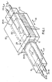
- FIG. 1 of the attached drawings illustrates a typical apparatus for use in accomplishing the separation of this invention.
- the central housing 10 of this invention includes two parallel plates 13 of magnetizable or magnetically permeable material, such as mild steel. This arrangement form a tunnel 28 through the center to receive filter elemtn carrier 11 movable there through.
- magnets 12 i.e. permanent magnets, electromagnets, or super-conducting magnets.
- Filter element carrier 11 in its simplest form is a long rectangular parallelepiped of nonmagnetizable material, e.g. copper, bronze, glass, plastic, or the like, with an internal space to hold two filter elements 20A and 20B, which might be fashioned with baffles and filled with steel wool so as to receive liquid or gaseous streams that will flow through, be dispersed throughout, and the solid magnetizable particles will be filtered therefrom.
- Each filter element 20A of 20B is connected to its own inlet and outlet liquid or gas streams to be treated for the separation of magnetizable particles from the remainder of the streams.
- Inlet stream 21B when filter 20B is located within tunnel 28, brings untreated material into element 20B and it eventually turns around at 23 and flows outwardly at 22B.
- inlet stream 21A brings untreated material into element 20A and it turns around at 24 and flow outwardly at 22A.
- the actual filtering operation functions only when respective element 20A or 20B is in the operative position of housing 10 to apply its full magnetic field on the passing stream, 21A or 21B. That position is shown in Fig. 1 for element 20A.
- the inoperative position of element 20B in Fig. 1 is for the cleaning operation to be applied to element 20B.
- Fig. 2 shows a side elevational view of the separator of this invention.
- Separator housing 10 includes a tunnel 28 between cover plates 13 in which filter carrier element 11 moves reciprocally right or left to put a filter element 20A or 20B in the field of the magnets in housing 10 to effect a separation of magnetizable material from nonmagnetizable material.
- Separating canister 25 separates the filtering operation on element 20A from that of element 20B.
- Dummy canisters 26A and 26B merely separate filter elements 20A and 20B from any other items that may be in carrier 11 as it is moved to place filter elements 20A or 20B in or out of the magnetic field in housing 10. They also aid the smooth movement of the entire carrier 11.
- the movement of carrier 11 reciprocally right of left may be controlled by any type of linear actuator 27.
- Raw material for separation is provided by stream 21A into element 20A while it is in position in the magnetic field in housing 10.
- the other filter element 20B is outside of the magnetic field and available for cleaning and rejuvenation so as to be available for reuse when needed and when element 20A is ready for cleaning.
- linear actuator 27 for moving carrier 11 may be used in the separator illustrated in Fig. 1, and in addition, may alternatively be used to move housing 10 which would be highly unlikely with the separator of U.S. Patent No. 5,743,410.
- Fig. 3 shows a cross-section of the magnetic field in housing 10.
- Tunnel 28 is the guideway for containing carrier 11 as it relatively moves reciprocally in the direction into and out from the surface of Fig. 3 between cover plates 13 above and below tunnel 28; and also between rows of magnets 12 on either side of tunnel 28.
- the magnetic field strength between plates 13 is approximately 0.5 Tesla.
- electromagnets of super-conductive magnets are employed between cover-plates 13, in accord with other embodiments of the invention, the magnetic field strength is approximately 2 Tesla.
- the type of separator disclosed in U.S. patent No. 5,743,410 relates more particularly to separators with field strengths above 5 Tesla and are considered to be high intensity in comparison to the low intensity type to which this invention applies.
Landscapes
- Filtering Of Dispersed Particles In Gases (AREA)
- Filtering Materials (AREA)
Abstract
Description
Claims (7)
- A magnetic separator for separating magnetizable particles from a continuous stream of particles in a fluid carrier, said separator including a housing having a plurality of magnetic elements producing a magnetic field around a generally horizontal tunnel extending through said housing, a nonmagnetic carrier relatively movable reciprocally through said tunnel and transporting at least two spaced filter containers containing magnetically activated filtration media and operatively connected to said continuous stream of particles, said carrier being alternatively positionable in the magnetic field or operational separation in one container and out of the magnetic field for cleaning while said continuous stream of particles continues to operate with another filter container on said carrier.
- The magnetic separator of Claim 1 wherein said housing is movable with respect to said carrier.
- The separator of Claim 1 wherein said carrier is movable with respect to said housing.
- The separator of Claim 1 wherein said plurality magnetic elements include a side-by-side arrangement as of permanent magnets extending along each side of said tunnel and extending generally the entire length of said tunnel.
- The separator of Claim 1 wherein said carrier includes a centrally located spacer between said at least two spaced filter elements.
- The magnetic separator of Claim 1 wherein said magnetic elements include a side-by-side arrangement of electromagnetic coils extending along each side of said tunnel and extending generally the entire length of said tunnel.
- The magnetic separator of Claim 1 wherein said magnetic elements include a side-by-side arrangement of super-conducting magnets extending along each side of said tunnel and extending generally the entire length of said tunnel.
Applications Claiming Priority (2)
| Application Number | Priority Date | Filing Date | Title |
|---|---|---|---|
| US51158600A | 2000-02-23 | 2000-02-23 | |
| US511586 | 2000-02-23 |
Publications (2)
| Publication Number | Publication Date |
|---|---|
| EP1127622A2 true EP1127622A2 (en) | 2001-08-29 |
| EP1127622A3 EP1127622A3 (en) | 2002-07-10 |
Family
ID=24035540
Family Applications (1)
| Application Number | Title | Priority Date | Filing Date |
|---|---|---|---|
| EP01104607A Withdrawn EP1127622A3 (en) | 2000-02-23 | 2001-02-23 | Low intensity magnetic separator |
Country Status (4)
| Country | Link |
|---|---|
| EP (1) | EP1127622A3 (en) |
| AU (1) | AU780530B2 (en) |
| BR (1) | BR0100753A (en) |
| ZA (1) | ZA200101210B (en) |
Cited By (2)
| Publication number | Priority date | Publication date | Assignee | Title |
|---|---|---|---|---|
| WO2018024819A1 (en) * | 2016-08-05 | 2018-02-08 | Haute Ecole D'ingenierie Et De Gestion Du Canton De Vaud (Heig-Vd) | Device for removing particles from a material in movement |
| CN113953085A (en) * | 2021-12-22 | 2022-01-21 | 潍坊新力超导磁电科技有限公司 | Sorting method of low-temperature superconducting magnetic separator |
Family Cites Families (2)
| Publication number | Priority date | Publication date | Assignee | Title |
|---|---|---|---|---|
| GB9309446D0 (en) * | 1993-05-07 | 1993-06-23 | Carpco Sms Ltd | Improvements in and relating to super-conducting magnets |
| EP0920916A1 (en) * | 1997-12-04 | 1999-06-09 | Forschungszentrum Karlsruhe GmbH | High gradient magnetic separator |
-
2001
- 2001-01-31 AU AU16752/01A patent/AU780530B2/en not_active Ceased
- 2001-02-13 ZA ZA200101210A patent/ZA200101210B/en unknown
- 2001-02-22 BR BR0100753A patent/BR0100753A/en not_active IP Right Cessation
- 2001-02-23 EP EP01104607A patent/EP1127622A3/en not_active Withdrawn
Cited By (2)
| Publication number | Priority date | Publication date | Assignee | Title |
|---|---|---|---|---|
| WO2018024819A1 (en) * | 2016-08-05 | 2018-02-08 | Haute Ecole D'ingenierie Et De Gestion Du Canton De Vaud (Heig-Vd) | Device for removing particles from a material in movement |
| CN113953085A (en) * | 2021-12-22 | 2022-01-21 | 潍坊新力超导磁电科技有限公司 | Sorting method of low-temperature superconducting magnetic separator |
Also Published As
| Publication number | Publication date |
|---|---|
| ZA200101210B (en) | 2001-08-16 |
| AU1675201A (en) | 2001-08-30 |
| EP1127622A3 (en) | 2002-07-10 |
| AU780530B2 (en) | 2005-03-24 |
| BR0100753A (en) | 2001-11-06 |
Similar Documents
| Publication | Publication Date | Title |
|---|---|---|
| US9352331B1 (en) | Filters for paramagnetic and diamagnetic substances | |
| EP0089200A1 (en) | A high-gradient magnetic separator | |
| US6210572B1 (en) | Filter and method for purifying liquids containing magnetic particles | |
| US5137629A (en) | Magnetic separator operating in a wet environment | |
| US4544482A (en) | Apparatus for extracting magnetizable particles from a fluid medium | |
| KR910004446B1 (en) | Method of washing off magnetically separated particles | |
| JP4926813B2 (en) | Apparatus for separating and removing fine magnetic particles | |
| AU680250B2 (en) | Improvements in and relating to magnetic separation systems | |
| AU780530B2 (en) | Low intensity magnetic separator | |
| JP2728848B2 (en) | Magnetic filter | |
| JPH02502705A (en) | Device for separating ferromagnetic materials from a flowing medium | |
| JP3826199B2 (en) | Magnetic separation device | |
| EP0429700B1 (en) | Apparatus for the continuous purification of liquids, and in particular of water, by means of the technique of high-gradient magnetic filtration | |
| JPS6159163B2 (en) | ||
| SU1604412A1 (en) | Electromagnetic filter | |
| RU2211092C2 (en) | Method of extraction of magnetic particles from liquid, gaseous and loose media and device for realization of this method | |
| JP3334067B2 (en) | Magnetic separation device and water treatment device with magnetic separation device | |
| RU2190453C1 (en) | High-gradient magnetic filter | |
| JPS61153117A (en) | Magnetic filter | |
| RU2165795C1 (en) | Method of purifying liquids from ferromagnetic particles | |
| RU197899U1 (en) | HIGH-GRADIENT MAGNETIC SEPARATOR MATRIX | |
| EP0341824A2 (en) | Apparatus for magnetic separation of impurities from fluids | |
| JP3851175B2 (en) | Magnetic separation device and magnetic separation method | |
| JPS6323707A (en) | Magnetic separator | |
| SU1607885A1 (en) | Precipitant for susceptible admixtures |
Legal Events
| Date | Code | Title | Description |
|---|---|---|---|
| PUAI | Public reference made under article 153(3) epc to a published international application that has entered the european phase |
Free format text: ORIGINAL CODE: 0009012 |
|
| AK | Designated contracting states |
Kind code of ref document: A2 Designated state(s): AT BE CH CY DE DK ES FI FR GB GR IE IT LI LU MC NL PT SE TR |
|
| AX | Request for extension of the european patent |
Free format text: AL;LT;LV;MK;RO;SI |
|
| PUAL | Search report despatched |
Free format text: ORIGINAL CODE: 0009013 |
|
| AK | Designated contracting states |
Kind code of ref document: A3 Designated state(s): AT BE CH CY DE DK ES FI FR GB GR IE IT LI LU MC NL PT SE TR |
|
| AX | Request for extension of the european patent |
Free format text: AL;LT;LV;MK;RO;SI |
|
| 17P | Request for examination filed |
Effective date: 20021219 |
|
| AKX | Designation fees paid |
Designated state(s): AT BE CH CY DE DK ES FI FR GB GR IE IT LI LU MC NL PT SE TR |
|
| 17Q | First examination report despatched |
Effective date: 20070220 |
|
| STAA | Information on the status of an ep patent application or granted ep patent |
Free format text: STATUS: THE APPLICATION IS DEEMED TO BE WITHDRAWN |
|
| 18D | Application deemed to be withdrawn |
Effective date: 20070703 |