EP1126767B2 - Cosmetic dispenser - Google Patents
Cosmetic dispenser Download PDFInfo
- Publication number
- EP1126767B2 EP1126767B2 EP99971273A EP99971273A EP1126767B2 EP 1126767 B2 EP1126767 B2 EP 1126767B2 EP 99971273 A EP99971273 A EP 99971273A EP 99971273 A EP99971273 A EP 99971273A EP 1126767 B2 EP1126767 B2 EP 1126767B2
- Authority
- EP
- European Patent Office
- Prior art keywords
- barrel
- applicator
- rod
- dispenser
- cosmetic dispenser
- Prior art date
- Legal status (The legal status is an assumption and is not a legal conclusion. Google has not performed a legal analysis and makes no representation as to the accuracy of the status listed.)
- Expired - Lifetime
Links
- 239000002537 cosmetic Substances 0.000 title claims description 52
- 239000007788 liquid Substances 0.000 claims abstract description 32
- 239000004744 fabric Substances 0.000 claims description 21
- 239000000463 material Substances 0.000 claims description 12
- 239000004745 nonwoven fabric Substances 0.000 claims description 8
- 239000002759 woven fabric Substances 0.000 claims description 6
- 230000002093 peripheral effect Effects 0.000 claims 1
- 210000003813 thumb Anatomy 0.000 abstract description 7
- 210000003811 finger Anatomy 0.000 abstract description 6
- 238000003825 pressing Methods 0.000 abstract description 3
- 239000006210 lotion Substances 0.000 abstract 2
- 239000000126 substance Substances 0.000 abstract 1
- 239000000835 fiber Substances 0.000 description 6
- 230000001166 anti-perspirative effect Effects 0.000 description 5
- 239000003213 antiperspirant Substances 0.000 description 5
- 239000002781 deodorant agent Substances 0.000 description 5
- 230000000994 depressogenic effect Effects 0.000 description 4
- -1 lipstick Substances 0.000 description 3
- 238000000034 method Methods 0.000 description 3
- 239000012229 microporous material Substances 0.000 description 3
- 235000011837 pasties Nutrition 0.000 description 3
- 239000004033 plastic Substances 0.000 description 3
- 229920003023 plastic Polymers 0.000 description 3
- 150000004291 polyenes Chemical class 0.000 description 3
- 229920000642 polymer Polymers 0.000 description 3
- 239000011148 porous material Substances 0.000 description 3
- 230000005484 gravity Effects 0.000 description 2
- 238000007789 sealing Methods 0.000 description 2
- 229920001169 thermoplastic Polymers 0.000 description 2
- 239000004416 thermosoftening plastic Substances 0.000 description 2
- 241000218157 Aquilegia vulgaris Species 0.000 description 1
- 239000004698 Polyethylene Substances 0.000 description 1
- 239000004743 Polypropylene Substances 0.000 description 1
- 230000001154 acute effect Effects 0.000 description 1
- 238000003490 calendering Methods 0.000 description 1
- 238000010276 construction Methods 0.000 description 1
- 230000001419 dependent effect Effects 0.000 description 1
- 238000004049 embossing Methods 0.000 description 1
- 239000002657 fibrous material Substances 0.000 description 1
- 238000002347 injection Methods 0.000 description 1
- 239000007924 injection Substances 0.000 description 1
- 238000001746 injection moulding Methods 0.000 description 1
- 239000007934 lip balm Substances 0.000 description 1
- 229920000573 polyethylene Polymers 0.000 description 1
- 229920001155 polypropylene Polymers 0.000 description 1
- 239000007787 solid Substances 0.000 description 1
Images


Classifications
-
- B—PERFORMING OPERATIONS; TRANSPORTING
- B65—CONVEYING; PACKING; STORING; HANDLING THIN OR FILAMENTARY MATERIAL
- B65D—CONTAINERS FOR STORAGE OR TRANSPORT OF ARTICLES OR MATERIALS, e.g. BAGS, BARRELS, BOTTLES, BOXES, CANS, CARTONS, CRATES, DRUMS, JARS, TANKS, HOPPERS, FORWARDING CONTAINERS; ACCESSORIES, CLOSURES, OR FITTINGS THEREFOR; PACKAGING ELEMENTS; PACKAGES
- B65D47/00—Closures with filling and discharging, or with discharging, devices
- B65D47/42—Closures with filling and discharging, or with discharging, devices with pads or like contents-applying means
-
- A—HUMAN NECESSITIES
- A45—HAND OR TRAVELLING ARTICLES
- A45D—HAIRDRESSING OR SHAVING EQUIPMENT; EQUIPMENT FOR COSMETICS OR COSMETIC TREATMENTS, e.g. FOR MANICURING OR PEDICURING
- A45D40/00—Casings or accessories specially adapted for storing or handling solid or pasty toiletry or cosmetic substances, e.g. shaving soaps or lipsticks
- A45D40/02—Casings wherein movement of the lipstick or like solid is a sliding movement
- A45D40/04—Casings wherein movement of the lipstick or like solid is a sliding movement effected by a screw
-
- B—PERFORMING OPERATIONS; TRANSPORTING
- B65—CONVEYING; PACKING; STORING; HANDLING THIN OR FILAMENTARY MATERIAL
- B65D—CONTAINERS FOR STORAGE OR TRANSPORT OF ARTICLES OR MATERIALS, e.g. BAGS, BARRELS, BOTTLES, BOXES, CANS, CARTONS, CRATES, DRUMS, JARS, TANKS, HOPPERS, FORWARDING CONTAINERS; ACCESSORIES, CLOSURES, OR FITTINGS THEREFOR; PACKAGING ELEMENTS; PACKAGES
- B65D83/00—Containers or packages with special means for dispensing contents
- B65D83/0005—Containers or packages provided with a piston or with a movable bottom or partition having approximately the same section as the container
- B65D83/0011—Containers or packages provided with a piston or with a movable bottom or partition having approximately the same section as the container moved by a screw-shaft
-
- A—HUMAN NECESSITIES
- A45—HAND OR TRAVELLING ARTICLES
- A45D—HAIRDRESSING OR SHAVING EQUIPMENT; EQUIPMENT FOR COSMETICS OR COSMETIC TREATMENTS, e.g. FOR MANICURING OR PEDICURING
- A45D2200/00—Details not otherwise provided for in A45D
- A45D2200/10—Details of applicators
- A45D2200/1009—Applicators comprising a pad, tissue, sponge, or the like
- A45D2200/1018—Applicators comprising a pad, tissue, sponge, or the like comprising a pad, i.e. a cushion-like mass of soft material, with or without gripping means
Definitions
- the present invention relates to a cosmetic dispenser that has improved ergonomic characteristics and which is easier to operate. More particularly, this invention relates to a cosmetic dispenser that has an upper application portion that is at an angle to the lower handle portion and which has an actuatorthat is located adjacent the angled applicator portion.
- Cosmetic dispensers which include dispensers for deodorants, antiperspirants, lipstick, lip balm, mascara and related products have a generally linear form. These dispensers range from round, to oval, to having a rectangular contour. In the deodorant/antiperspirant area the dispensers presently are oval in shape or have a rectangular contour. Illustrative of such dispensers are the dispensers of U.S. Patent 5,275,496, U.S. Patent 5,753,212 and U.S. Design Patent 379,927. These are very useful dispensers and provide ease in the application of the deodorant/antiperspirant product. However, there is a continuing need for dispensers that are easier to hold and to use.
- the problem is to improve the ergonomics of the dispenser. Also, it is desired to improve the application of the contained product onto a person's skin. This entails the structure of the applicator surface of the dispenser and the shape of this applicator surface. Further, in the ejection of the contained product there is a need to improve the location of the dispenser actuator to improve the ergonomics of the dispenser, in particular, it would be useful to have single hand actuation of the dispenser during use in contrast to two hand actuation and then a subsequent use. Present dispensers require a holding in one hand and a rotating of a knob at the bottom of the dispenser, or the pressing of an actuator button at the bottom of the dispenser by the other hand. This is not a highly desirable way to use an applicator
- the present dispenser solves these and other problems. It has improved ergonomics. It is easier to hold.
- the applicator surface is at an angle to the dispenser body improving ease of use.
- the applicator surface is of an improved structure.
- the dispenser actuator is moved to a point intermediate the ends thereby providing for single hand use.
- the dispenser can be actuated by a person's thumb while being gripped by the other four fingers. A person's thumb can rotate a knob or depress an actuator.
- US 1,971,127 discloses a dispenser for a viscous liquid comprising the features of the preambles of claims 1 and 14.
- US 3,616,970 discloses a container for dispensing a pasty mass. It comprises a sleeve member having a cover member at one end thereof from which the pasty mass is discharged. In the sleeve member a piston and a threaded spindle are mounted such that, the piston is axially displaceable by rotation of the spindle. An actuator is provided for rotating the spindle, and an applicator element located at the discharge end of the container serves to distribute the pasty mass.
- the present invention provides a container for dispensing a viscious liquid as claimed in claims 1 and 14.
- Advantageous versions of the invention follow from the respective dependent claims.
- the invention is directed to a cosmetic dispenser that has improved ergonomics.
- the dispenser is easier to hold, to actuate and to apply a cosmetic product to a person's person's skin.
- the dispenser comprises a barrel of a generally oval shape. Extending upwardly from the barrel, and at an angle from the vertical (longitudinal) axis of the barrel is an applicator.
- the cosmetic product to be dispensed is stored in the barrel and dispensed onto a person's skin by the applicator.
- the actuator upon being depressed or rotated causes the product contained in the barrel to be dispensed.
- the actuator is located at about the junction of the barrel and the applicator. At this location the dispenser can be gripped with four fingers around the barrel and with the thumb available to rotate or depress the actuator.
- the applicator surface for applying a cosmetic product such as a deodorant or antiperspirant onto one's skin can have various structures and shapes.
- the shape can be oval, a rectangular contour, generally triangular or of many other shapes.
- the surface of the applicator can be microporous to generally porous to a series of apertures of a relatively large diameter.
- a microporous structure can be a microporous polymer.
- a generally porous structure can be a woven or nonwoven mesh fabric.
- a nonwoven mesh fabric can be an extruded material with a plurality of apertures or can be a layer of random arrayed fibers. Regardless of the applicator surface, the dispenser shape provides for an added ease of handling.
- the cosmetic dispensers of the present invention have a new ergonomic shape for ease in gripping, actuation and use. This includes having the actuator in an upper part of the dispenser rather than at the base of the dispenser. In this way the dispenser can be held in one hand and actuated and used without changing the position in the hand. With the actuator at an upper part of the dispenser, the thumb can actuate the dispenser while also gripping the dispenser. The remaining four fingers traverse the rear surface of the dispenser and form the other part of the grip. The dispenser is gripped between the thumb and the remaining four fingers. The angled structure of the dispenser makes it easier to apply the contained products to the underarm area and other body areas.
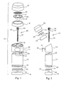
- FIG. 1 is a front exploded view of the cosmetic dispenser 10.
- the cosmetic dispenser which is particularly adapted for the application deodorants and antiperspirants, is comprised of the main parts of a barrel 12, barrel extension 14, applicator 18 and closure 20.
- the barrel 12 is closed by lower cover 16 which is held onto the barrel as a snap fit over ridge 28.
- the piston elevator has a sealing ring 24. This sealing ring prevents the cosmetic material from flowing downwardly around the piston elevator.
- conduits 27 On the upper part of the barrel are conduits 27 for flowing the cosmetic up into the conduits 32 in the barrel extension.
- Tabs 25 are guide tabs for aligning the barrel and the barrel extension.
- the barrel extension has the actuator for rotating the rod 40 which has a lower threaded screw 42 and an upper gear 44.
- the recess area 43 is for rotatably locking the rod 40 in barrel extension 14.
- the lower threaded portion 42 is threaded onto piston elevator 22 through threaded orifice 26.
- the applicator 18 holds the distributor 46.
- the cosmetic flows from conduits 32 into conduits 48 in the distributor to the distributor top surface 47.
- Closing the top surface of the distributor is applicator surface 50.
- the applicator surface can be a microporous material to a porous mesh fabric material. The applicator is closed by closure 20.
- Figure 2 shows a side exploded view of the dispenser of Figure 1 This view shows the same parts of Figure 1 but with the actuator shown in more detail.
- the actuator has an inwardly extending leaf spring 31.
- the barrel 12 has closure 16 at one end and barrel extension 14 at the other end.
- Piston elevator 22 rides in barrel 12 and responds to the rotation of rod 40 upon which it is threaded.
- the actuator 30 rotates gear 44 of the rod which raises the piston elevator to dispense product into distributor 46 and through the applicator surface 50.
- Figure 3 is a cross-sectional view of the assembled dispenser along a plane parallel to the major axis of the dispenser.
- the cap 16 is snap fitted onto the barrel 12 at ridge 11.
- the barrel extension is snap fitted onto the top of the barrel.
- the rod 40 is shown in a rotatable relationship with upperwall 17 of the barrel.
- Conduits 32 will flow cosmetic material from the interior of barrel 12 upon rotation of rod 40 and the upward movement of the piston elevator to interfitting conduits 48 of the distributor.
- the cosmetic material passes up to the surface below applicator surface 50.
- This structure is shown in Figure 4 in a cross-sectional view of the assembled dispenser in a plane parallel to the minor axis. The parts have been described with regard to the prior figures. Additionally, in this view the angle of the dispenser is shown in more detail and the angle x is an angle of about 5° to 75° and preferably about 10° to 50° to the vertical, i.e. longitudinal, axis of the barrel.
- Figure 5 is an exploded perspective view of the dispenser. This view shows an alternative embodiment for the piston elevator and for the distributor.
- the piston elevator is shown with two piston seals 24. There is an upper and lower seal with a concave region between these two seals.
- the distributor is shown with two distribution channels 49.
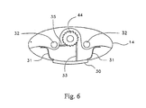
- FIG 6 is a top plan view of the cosmetic dispenser of Figure 1 showing the actuator assembly.
- the actuator assembly is comprised of the actuator 30 with a leaf spring 31 extending from each end of the actuator.
- a drive rod 33 extends from the actuator and contacts gear 44 of rod 40.
- the drive rod moves the gear counterclockwise which moves the threaded piston elevator upward.
- the locking rod 35 prevents the gear 44 from reversing and backing off.
- the leaf springs 31 return the actuator to its original position.
- Figure 7 is a side elevational view of the dispenser fully assembled.
- the dispenser By grasping the barrel 12 with the thumb on the front adjacent the actuator on the barrel extension and the other four fingers on the rear surface of the barrel, the dispenser can be handled and used using a single hand.
- the shape of the dispenser and the location of the actuator provides for improved ergonomics for the dispenser.
- Dispenser 60 has a barrel 62 for containing the cosmetic to be dispensed.
- the lower section 64 contains the actuator mechanism to raise piston elevator 74, i.e. viscous liquid holder, to dispense the product contained in the barrel.
- the barrel 62 is closed on the upper end by angled barrel extension 66.
- An applicator surface 70 such as a dispensing screen is mounted onto the applicatorsection 68.
- the product flows to the applicator section 68 by means of conduit 72. There can be more than one conduit.
- the product in barrel 62 is flowed through conduit 72 when piston elevator 74 is raised upwardly on threaded rod 76.
- the rotation of threaded rod 76 causes threadedly engaged piston elevator 74 to move upwardly on threaded rod 76 .
- a seal ring 75 provides a seal of the piston elevator to the barrel 62 .
- the threaded rod 76 is rotated by means of actuatorbutton 78.
- actuator button 78 When the actuator button is depressed drive road 79 contacts gear 77, rotating this gear, and thus, rod 76 which is connected to this gear.
- the angle of the barrel extension 66 aids in the application of a product to a skin surface. This angle can be the same as or similar to that of the dispenser of Figure 1.
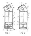
- FIG. 9 there is shown a further embodiment of the dispenser.
- the dispensing of product is by means of rotating an actuator knob in the base of the dispenser.
- the dispenser 80 has barrel 82, angled barrel extension 86 and applicator 88 which has an applicator screen 90.
- the product to be dispensed flows from barrel 82 through conduit 92 to the applicator and screen 90.
- piston elevator 94 Located in barrel 82 is piston elevator 94, i.e. the viscous liquid holder.
- the piston elevator is sealed in barrel 82 by means of seal ring 95 on piston elevator 94.
- the piston elevator threadedly engages threaded rod 96 which is rotated by means of knob 84.
- the applicator surfaces 50, 70 and 90 of the dispenser applicator 18 can be a microporous material through to porous mesh materials.
- a typical porous material can be a material that is marketed under the Porex® trademark. This is a microporous material of random interconnecting channels of a varying pore diameter. It is a porous polyene that usually is molded in the form in which it is to be used.
- the porous materials will be a woven or nonwoven fabric.
- the nonwoven fabrics can be a layer of randomly arrayed fibers or it can be an extruded film with apertures of a given size and array.
- the fabric can be of any of the three basic weaves. These are the plain, twill or satin weaves. If a plain weave this can be a regular plain weave, oxford weave, lousine weave, 2 x 2 basket weave, 3 x 2 basket weave, 3 x 3 basket weave, 4 x 4 basket weave, 4 x 5 basket weave, 3 x 5 basket weave and an 8 x 8 basket weave.
- the fabric can be of a rip stop parachute type. In this type of weave there is an intermittent weave to stop any rips in the fabric.
- the twill fabrics can be a 2/1 right hand twill, a 1/2 right hand twill, a 2/2 right hand twill, a 3/1 right hand twill, a 3/1 45° right hand twill.
- the satin fabrics can be a 4 harness satin (i.e. crowfoot), 5 harness satin, 6 harness satin, a 7 harness satin or an 8 harness satin. These are all forms in which the fibers are interlaced in the warp and fill directions.
- the warp threads usually are called ends while the filling threads are called picks.
- the edges of the fabric are the selvage.
- the construction of a woven fabric is given as ends x picks per inch.
- the weave can be balanced where there is the same number of threads in the warp direction and in the filling direction. In an unbalanced weave there will be more threads either in the warp direction or in the filling direction.
- Denier is the weight in grams for 9000 meters of a thread.
- a low denier indicates a fine, relatively narrow cross-section thread.
- a higher specific gravity material at a given denier will have a smaller cross-section than a lower specific gravity material at that same denier.
- the texture of the fabric can be changed.
- the skin feel can range from smooth to rough.
- calendaring or similarly treating the fabric the surface of the fabric can be modified to produce a smoother texture and skin feel.
- the skin feel and the application also can be adjusted by the tension on the fabric in its attachment to the applicator frame.
- the flexibility of the fabric can be modified.
- the fabric can be supported or unsupported. If supported, it can be supported along the major axis and/or along the minor axis, assuming the usual oval shape of an applicator surface. If the applicator is round, it can be supported by means of one or more diametric supports.
- the fabric can be an extruded film that by its structure is porous, or is a solid film which is perforated to make it porous.
- a non-woven fabric can be comprised of a plurality of short length fibers that are layed down in a random array and then selectively bonded together adhesively or by heat bonding.
- the former extruded apertured films can be produced by the processes disclosed in U.S. Patent 4,842,794 or U.S. Patent 5,207,962.
- U.S. Patent 4,842,794 a sheet of thermoplastic film is extruded to a thickness of about 0.5 to 20 mils.
- One side of the film is provided with about 4 to 60 grooves per centimeter and the other side a set of grooves at an acute angle of 15° and 75°.
- the embossing rolls that have the patterns are at a pressure of about 4 to 120 pounds per linear centimeter.
- the result is a film with oval apertures.
- the film then can be uniaxially oriented in the machine or cross direction from about 50% to 500%, or sequentially biaxially oriented in the machine direction and cross direction up to about 600%.
- the extruded and apertured film can be heat treated to increase the size of the apertures.
- thermoplastic film is extruded with the extruded film passed between a pattemed nip roll and a smooth roll.
- the patterned nip roll has a plurality of raised projections with a sharp distal end. These sharp raised projections from the apertures in the film.
- the apertured film then can be uniaxially oriented in the machine or cross direction or biaxially oriented in both the machine direction and cross direction.
- the apertures will be of the shape and size of the distal end of the raised projections.
- the apertures also will be in a consistent repeating pattern.
- the extruded film also can be produced in the form of a sheet or in a plurality of strands. When extruded in the form of strands, these strands are in a sheet in a helical type of pattern. This also is known as a biplanar netting.
- the film that is produced in the form of helical strands can have 7 to 40 strands per 2.54 cm, be in a width of 30.48cm to 152.4cm and a thickness of 4 033cm to .20cm.
- the apertures can be in a size range of 100 to 500 micron and larger.
- the open area of the extruded strand type film can range from about 4% to 25% or more. Larger openings will provide a greater open area.
- Useful non-woven netting products are the 4 Naltex® products of Nalle Plastics, Inc.
- the other parts of the cosmetic dispenser can be made using any injection moldable plastics.
- the preferred plastics are polyenes such as polyethylene and polypropylene and ABS (alkylbutylstyrene) polymers. 5 Injection molding is a relatively inexpensive process and the polyene and ABS polymers are likewise of a relatively low cost.
Landscapes
- Engineering & Computer Science (AREA)
- Mechanical Engineering (AREA)
- Coating Apparatus (AREA)
- Closures For Containers (AREA)
- Cosmetics (AREA)
- Acyclic And Carbocyclic Compounds In Medicinal Compositions (AREA)
- Media Introduction/Drainage Providing Device (AREA)
- Containers And Packaging Bodies Having A Special Means To Remove Contents (AREA)
Abstract
Description
- The present invention relates to a cosmetic dispenser that has improved ergonomic characteristics and which is easier to operate. More particularly, this invention relates to a cosmetic dispenser that has an upper application portion that is at an angle to the lower handle portion and which has an actuatorthat is located adjacent the angled applicator portion.
- Cosmetic dispensers which include dispensers for deodorants, antiperspirants, lipstick, lip balm, mascara and related products have a generally linear form. These dispensers range from round, to oval, to having a rectangular contour. In the deodorant/antiperspirant area the dispensers presently are oval in shape or have a rectangular contour. Illustrative of such dispensers are the dispensers of U.S. Patent 5,275,496, U.S. Patent 5,753,212 and U.S. Design Patent 379,927. These are very useful dispensers and provide ease in the application of the deodorant/antiperspirant product. However, there is a continuing need for dispensers that are easier to hold and to use.
- The problem is to improve the ergonomics of the dispenser. Also, it is desired to improve the application of the contained product onto a person's skin. This entails the structure of the applicator surface of the dispenser and the shape of this applicator surface. Further, in the ejection of the contained product there is a need to improve the location of the dispenser actuator to improve the ergonomics of the dispenser, in particular, it would be useful to have single hand actuation of the dispenser during use in contrast to two hand actuation and then a subsequent use. Present dispensers require a holding in one hand and a rotating of a knob at the bottom of the dispenser, or the pressing of an actuator button at the bottom of the dispenser by the other hand. This is not a highly desirable way to use an applicator
- The present dispenser solves these and other problems. It has improved ergonomics. It is easier to hold. The applicator surface is at an angle to the dispenser body improving ease of use. The applicator surface is of an improved structure. Further, the dispenser actuator is moved to a point intermediate the ends thereby providing for single hand use. The dispenser can be actuated by a person's thumb while being gripped by the other four fingers. A person's thumb can rotate a knob or depress an actuator.
- US 1,971,127 discloses a dispenser for a viscous liquid comprising the features of the preambles of
claims 1 and 14. - US 3,616,970 discloses a container for dispensing a pasty mass. It comprises a sleeve member having a cover member at one end thereof from which the pasty mass is discharged. In the sleeve member a piston and a threaded spindle are mounted such that, the piston is axially displaceable by rotation of the spindle. An actuator is provided for rotating the spindle, and an applicator element located at the discharge end of the container serves to distribute the pasty mass.
- The present invention provides a container for dispensing a viscious liquid as claimed in
claims 1 and 14. Advantageous versions of the invention follow from the respective dependent claims. - The invention is directed to a cosmetic dispenser that has improved ergonomics. The dispenser is easier to hold, to actuate and to apply a cosmetic product to a person's person's skin. The dispenser comprises a barrel of a generally oval shape. Extending upwardly from the barrel, and at an angle from the vertical (longitudinal) axis of the barrel is an applicator. The cosmetic product to be dispensed is stored in the barrel and dispensed onto a person's skin by the applicator.
- Intermediate to the ends of the dispenser there is an actuator. The actuator upon being depressed or rotated causes the product contained in the barrel to be dispensed. In a preferred embodiment the actuator is located at about the junction of the barrel and the applicator. At this location the dispenser can be gripped with four fingers around the barrel and with the thumb available to rotate or depress the actuator.
- The applicator surface for applying a cosmetic product such as a deodorant or antiperspirant onto one's skin can have various structures and shapes. The shape can be oval, a rectangular contour, generally triangular or of many other shapes. The surface of the applicator can be microporous to generally porous to a series of apertures of a relatively large diameter. A microporous structure can be a microporous polymer. A generally porous structure can be a woven or nonwoven mesh fabric. A nonwoven mesh fabric can be an extruded material with a plurality of apertures or can be a layer of random arrayed fibers. Regardless of the applicator surface, the dispenser shape provides for an added ease of handling.
-
- Figure 1 is a front exploded view of the cosmetic dispenser of the present invention.
- Figure 2 is a side exploded view of the dispenser of Figure 1.
- Figure 3 is cross-sectional view of the cosmetic dispenser of Figure 1 in a plan through the major axis of the dispenser.
- Figure 4 is a cross-sectional view of the top of the cosmetic dispenser of Figure 1 in a plan through the minor axis of the dispenser.
- Figure 5 is an exploded perspective view of the dispenser of Figure 1.
- Figure 6 is a top plan view of the barrel extension of the applicator of Figure 1.
- Figure 7 is a side elevational view of the dispenser.
- Figure 8 is a side elevational view in cross-section of an embodiment of the dispenser with an actuator at a lower portion.
- Figure 9 is a side elevational view in cross-section of an embodiment of the dispenser with a rotating knob actuator.
- The cosmetic dispensers of the present invention have a new ergonomic shape for ease in gripping, actuation and use. This includes having the actuator in an upper part of the dispenser rather than at the base of the dispenser. In this way the dispenser can be held in one hand and actuated and used without changing the position in the hand. With the actuator at an upper part of the dispenser, the thumb can actuate the dispenser while also gripping the dispenser. The remaining four fingers traverse the rear surface of the dispenser and form the other part of the grip. The dispenser is gripped between the thumb and the remaining four fingers. The angled structure of the dispenser makes it easier to apply the contained products to the underarm area and other body areas.
- Figure 1 is a front exploded view of the
cosmetic dispenser 10. The cosmetic dispenser, which is particularly adapted for the application deodorants and antiperspirants, is comprised of the main parts of abarrel 12,barrel extension 14,applicator 18 andclosure 20. Thebarrel 12 is closed bylower cover 16 which is held onto the barrel as a snap fit overridge 28. Thepiston elevator 22, i.e. viscous liquid holder, rides inbarrel 12 with the cosmetic material to be dispensed located above this piston elevator. In this view the piston elevator has a sealingring 24. This sealing ring prevents the cosmetic material from flowing downwardly around the piston elevator. - On the upper part of the barrel are
conduits 27 for flowing the cosmetic up into theconduits 32 in the barrel extension.Tabs 25 are guide tabs for aligning the barrel and the barrel extension. The barrel extension has the actuator for rotating therod 40 which has a lower threadedscrew 42 and anupper gear 44. Therecess area 43 is for rotatably locking therod 40 inbarrel extension 14. The lower threadedportion 42 is threaded ontopiston elevator 22 through threadedorifice 26. - The
applicator 18 holds thedistributor 46. The cosmetic flows fromconduits 32 intoconduits 48 in the distributor to thedistributor top surface 47. Closing the top surface of the distributor isapplicator surface 50. The applicator surface can be a microporous material to a porous mesh fabric material. The applicator is closed byclosure 20. - Figure 2 shows a side exploded view of the dispenser of Figure 1 This view shows the same parts of Figure 1 but with the actuator shown in more detail. The actuator has an inwardly extending
leaf spring 31. Thebarrel 12 hasclosure 16 at one end andbarrel extension 14 at the other end.Piston elevator 22 rides inbarrel 12 and responds to the rotation ofrod 40 upon which it is threaded. Theactuator 30 rotatesgear 44 of the rod which raises the piston elevator to dispense product intodistributor 46 and through theapplicator surface 50. - Figure 3 is a cross-sectional view of the assembled dispenser along a plane parallel to the major axis of the dispenser. The
cap 16 is snap fitted onto thebarrel 12 atridge 11. The barrel extension is snap fitted onto the top of the barrel. Therod 40 is shown in a rotatable relationship withupperwall 17 of the barrel.Conduits 32 will flow cosmetic material from the interior ofbarrel 12 upon rotation ofrod 40 and the upward movement of the piston elevator tointerfitting conduits 48 of the distributor. The cosmetic material passes up to the surface belowapplicator surface 50. This structure is shown in Figure 4 in a cross-sectional view of the assembled dispenser in a plane parallel to the minor axis. The parts have been described with regard to the prior figures. Additionally, in this view the angle of the dispenser is shown in more detail and the angle x is an angle of about 5° to 75° and preferably about 10° to 50° to the vertical, i.e. longitudinal, axis of the barrel. - Figure 5 is an exploded perspective view of the dispenser. This view shows an alternative embodiment for the piston elevator and for the distributor. The piston elevator is shown with two piston seals 24. There is an upper and lower seal with a concave region between these two seals. The distributor is shown with two
distribution channels 49. - Figure 6 is a top plan view of the cosmetic dispenser of Figure 1 showing the actuator assembly. The actuator assembly is comprised of the
actuator 30 with aleaf spring 31 extending from each end of the actuator. Adrive rod 33 extends from the actuator and contacts gear 44 ofrod 40. When the button is depressed, the drive rod moves the gear counterclockwise which moves the threaded piston elevator upward. The lockingrod 35 prevents thegear 44 from reversing and backing off. After the actuator has been depressed theleaf springs 31 return the actuator to its original position. - Figure 7 is a side elevational view of the dispenser fully assembled. By grasping the
barrel 12 with the thumb on the front adjacent the actuator on the barrel extension and the other four fingers on the rear surface of the barrel, the dispenser can be handled and used using a single hand. The shape of the dispenser and the location of the actuator provides for improved ergonomics for the dispenser. - In Figure 8 there is the embodiment of the dispenser with the actuator mechanism located at the base of the dispenser unit rather than in the region of angle.
Dispenser 60 has abarrel 62 for containing the cosmetic to be dispensed. Thelower section 64 contains the actuator mechanism to raisepiston elevator 74, i.e. viscous liquid holder, to dispense the product contained in the barrel. Thebarrel 62 is closed on the upper end byangled barrel extension 66. Anapplicator surface 70, such as a dispensing screen is mounted onto theapplicatorsection 68. The product flows to theapplicator section 68 by means ofconduit 72. There can be more than one conduit. - The product in
barrel 62 is flowed throughconduit 72 whenpiston elevator 74 is raised upwardly on threadedrod 76. The rotation of threadedrod 76 causes threadedly engagedpiston elevator 74 to move upwardly on threadedrod 76 . Aseal ring 75 provides a seal of the piston elevator to thebarrel 62 . - The threaded
rod 76 is rotated by means ofactuatorbutton 78. When the actuator button isdepressed drive road 79contacts gear 77, rotating this gear, and thus,rod 76 which is connected to this gear. The angle of thebarrel extension 66 aids in the application of a product to a skin surface. This angle can be the same as or similar to that of the dispenser of Figure 1. - In Figure 9 there is shown a further embodiment of the dispenser. In this embodiment the dispensing of product is by means of rotating an actuator knob in the base of the dispenser. The
dispenser 80 hasbarrel 82,angled barrel extension 86 andapplicator 88 which has anapplicator screen 90. The product to be dispensed flows frombarrel 82 throughconduit 92 to the applicator andscreen 90. Located inbarrel 82 ispiston elevator 94, i.e. the viscous liquid holder. The piston elevator is sealed inbarrel 82 by means ofseal ring 95 onpiston elevator 94. The piston elevator threadedly engages threadedrod 96 which is rotated by means ofknob 84. Upon the rotation ofknob 84 threadedrod 96 rotates andpiston elevator 94 rises inbarrel 82. The product inbarrel 82 then flows throughconduit 92 to thescreen 90 whereupon it can be applied to a surface, such as a skin surface. The angle of the barrel extension will be the same as or similar to that of the dispenser of Figure 1. - The applicator surfaces 50, 70 and 90 of the
dispenser applicator 18 can be a microporous material through to porous mesh materials. A typical porous material can be a material that is marketed under the Porex® trademark. This is a microporous material of random interconnecting channels of a varying pore diameter. It is a porous polyene that usually is molded in the form in which it is to be used. The porous materials will be a woven or nonwoven fabric. The nonwoven fabrics can be a layer of randomly arrayed fibers or it can be an extruded film with apertures of a given size and array. - If a woven fabric the fabric can be of any of the three basic weaves. These are the plain, twill or satin weaves. If a plain weave this can be a regular plain weave, oxford weave, lousine weave, 2 x 2 basket weave, 3 x 2 basket weave, 3 x 3 basket weave, 4 x 4 basket weave, 4 x 5 basket weave, 3 x 5 basket weave and an 8 x 8 basket weave. In addition the fabric can be of a rip stop parachute type. In this type of weave there is an intermittent weave to stop any rips in the fabric. The twill fabrics can be a 2/1 right hand twill, a 1/2 right hand twill, a 2/2 right hand twill, a 3/1 right hand twill, a 3/1 45° right hand twill. The satin fabrics can be a 4 harness satin (i.e. crowfoot), 5 harness satin, 6 harness satin, a 7 harness satin or an 8 harness satin. These are all forms in which the fibers are interlaced in the warp and fill directions. The warp threads usually are called ends while the filling threads are called picks. The edges of the fabric are the selvage.
- The construction of a woven fabric is given as ends x picks per inch. The weave can be balanced where there is the same number of threads in the warp direction and in the filling direction. In an unbalanced weave there will be more threads either in the warp direction or in the filling direction.
- The tightness for a fabric can be calculated by the formula:

- Also of importance is the denier of the threads. Denier is the weight in grams for 9000 meters of a thread. A low denier indicates a fine, relatively narrow cross-section thread. A higher specific gravity material at a given denier will have a smaller cross-section than a lower specific gravity material at that same denier.
- There are many variables in the selection of a woven fabric. By the selection of the weave style, fabric tightness, fiber material, fiber structure and fiber denier, the texture of the fabric can be changed. The skin feel can range from smooth to rough. By calendaring or similarly treating the fabric, the surface of the fabric can be modified to produce a smoother texture and skin feel. The skin feel and the application also can be adjusted by the tension on the fabric in its attachment to the applicator frame. The flexibility of the fabric can be modified. Also, the fabric can be supported or unsupported. If supported, it can be supported along the major axis and/or along the minor axis, assuming the usual oval shape of an applicator surface. If the applicator is round, it can be supported by means of one or more diametric supports.
- If the fabric is non-woven, it can be an extruded film that by its structure is porous, or is a solid film which is perforated to make it porous. In addition, a non-woven fabric can be comprised of a plurality of short length fibers that are layed down in a random array and then selectively bonded together adhesively or by heat bonding. The former extruded apertured films can be produced by the processes disclosed in U.S. Patent 4,842,794 or U.S. Patent 5,207,962. In U.S. Patent 4,842,794 a sheet of thermoplastic film is extruded to a thickness of about 0.5 to 20 mils. One side of the film is provided with about 4 to 60 grooves per centimeter and the other side a set of grooves at an acute angle of 15° and 75°. The embossing rolls that have the patterns are at a pressure of about 4 to 120 pounds per linear centimeter. The result is a film with oval apertures. The film then can be uniaxially oriented in the machine or cross direction from about 50% to 500%, or sequentially biaxially oriented in the machine direction and cross direction up to about 600%. In the alternative the extruded and apertured film can be heat treated to increase the size of the apertures.
- In the processes of U.S. Patent 5,207,962 a thermoplastic film is extruded with the extruded film passed between a pattemed nip roll and a smooth roll. The patterned nip roll has a plurality of raised projections with a sharp distal end. These sharp raised projections from the apertures in the film. The apertured film then can be uniaxially oriented in the machine or cross direction or biaxially oriented in both the machine direction and cross direction. The apertures will be of the shape and size of the distal end of the raised projections. The apertures also will be in a consistent repeating pattern. These extruded films are a class of non-woven fabrics for the purposes of this invention.
- The extruded film also can be produced in the form of a sheet or in a plurality of strands. When extruded in the form of strands, these strands are in a sheet in a helical type of pattern. This also is known as a biplanar netting. The film that is produced in the form of helical strands can have 7 to 40 strands per 2.54 cm, be in a width of 30.48cm to 152.4cm and a thickness of 4 033cm to .20cm. The apertures can be in a size range of 100 to 500 micron and larger. The open area of the extruded strand type film can range from about 4% to 25% or more. Larger openings will provide a greater open area. Useful non-woven netting products are the 4 Naltex® products of Nalle Plastics, Inc.
- The other parts of the cosmetic dispenser can be made using any injection moldable plastics. The preferred plastics are polyenes such as polyethylene and polypropylene and ABS (alkylbutylstyrene) polymers. 5 Injection molding is a relatively inexpensive process and the polyene and ABS polymers are likewise of a relatively low cost.
Claims (27)
- A cosmetic, dispenser (10, 60, 80) for a viscous liquid comprising:a barrel (12, 62, 82) for containing said viscous liquid, having a longitudinal axis, closed at a first end;a viscous liquid holder (22, 74, 94) in said barrel (12, 62, 82) and moveably connected to a rod (40, 76, 96) whereby upon the rotation of said rod (40, 76, 96) said viscous liquid holder (22) is moved longitudinally in said barrel (12, 62, 82);an actuator (30, 78, 84) in contact with said (40, 76, 96) rod for the rotation of said rod (40, 76, 96);characterized in that there is a barrel extension (14, 66, 86) which extends upwardly and forwardly at an angle to the longitudinal axis of said barrel (12, 62, 82), with a portion beyond the periphery of said barrel (12, 62, 82), a first end of said barrel extension (14, 66, 86) closing a second end (23) of said barrel (12, 62, 82), a second end of said barrel extension (14, 66, 86) having an applicator (18, 68, 88) with a viscous liquid porous applicator surface (50, 70, 90) for said viscous liquid attached thereto, said applicator (18, 68, 88) being at an angle to the longitudinal axis of said barrel (12, 62, 82) whereby a peripheral edge thereof has a greater height above said barrel (12, 62, 82) than the remainder of said porous liquid applicator; andat least one barrel extension conduit (32) within said barrel extension (14, 66, 86) connecting said barrel (12, 62, 82) to a lower portion of said applicator (18, 68, 88) whereby upon the actuation of said actuator (30, 78, 84) said viscous liquid flows from said barrel (12, 62, 82) to said applicator (18, 68, 88) with said porous applicator surface (50, 70, 90).
- A cosmetic dispenser (10, 60, 80) as in claim 1 wherein said rod (40, 76, 96) is a threaded rod along more than half the length thereof, said rod threadedly engaging said viscous liquid holder (22, 74, 94) whereby upon the rotation of said rod (40, 76, 96) said viscous liquid holder (22, 74, 94) can be moved in said barrel (12, 62, 82) toward said applicator (18, 68, 88).
- A cosmetic dispenser (10, 60, 80) as in claim 1 wherein said actuator (30, 78, 84) is located in said barrel extension and an upper portion of said rod (40, 76, 96) extends into said barrel extension (14, 66, 86) and has a mechanism attached thereto whereby upon contact with said actuator (30, 78, 84) said rod (40, 76, 96) is rotated.
- A cosmetic dispenser (10, 60, 80) as in claim 1 wherein the upper portion of said barrel extension (14, 66, 86) is at an angle of about 5° to 75° to the longitudinal axis of said barrel (12, 62, 82).
- A cosmetic dispenser (10, 60, 80) as in claim 1 wherein there are at least two barrel extension conduits (32) for connecting said barrel (12, 62, 82) to a lower portion of said applicator (18, 68, 88).
- A cosmetic dispenser (10, 60, 80) as in claim 1 wherein the surface of said porous liquid applicator surface (50, 70, 90) is a microporous polymeric material.
- A cosmetic dispenser (10, 60, 80) as in claim 1 wherein the surface of said porous liquid applicator surface (50, 70, 90) is a porous woven fabric.
- A cosmetic dispenser (10, 60, 80) as in claim 1 wherein the surface of said viscous porous liquid applicator surface (50, 70, 90) is a porous nonwoven fabric.
- A cosmetic dispenser (10, 60, 80) as in claim 8 wherein said nonwoven fabric is an extruded fabric with a plurality of apertures.
- A cosmetic dispenser (10, 60, 80) as in claim 1 wherein said actuator (30, 78, 84) has at least one drive arm (33) extending inwardly of said barrel extension (14, 66, 86), said at least one drive arm (33) contacting said mechanism for rotating said rod.
- A cosmetic dispenser (10, 60, 80) as in claim 10 wherein said rod (40, 76, 96) has a plurality of gear teeth (44) around an upper part thereof, said at least one drive arm (33) contacting said plurality of gear teeth (44) and rotating said rod (40, 76, 96).
- A cosmetic dispenser (10, 60, 80) as in claim 1 wherein said actuator (30, 78, 84) is located at a first end of said barrel (12, 62, 82).
- A cosmetic dispenser (80) as in claim 12 wherein said actuator (84) is a knob at the base of said cosmetic dispenser (10, 60, 80) which rotates said rod (96).
- A cosmetic dispenser (10, 60, 80) for a viscous liquid comprising:a barrel (12, 62, 82) containing said viscous liquid, said barrel (12, 62, 82) closed at a first end and a barrel extension (14, 66, 86) on a second end;a viscous liquid holder (22, 74, 94) in said barrel (12, 62, 82) and moveably connected to a rod (40, 76, 96), an upper end of said rod (40, 76, 96) extending into said barrel extension (14, 66, 86) and having part of a mechanism for rotating said rod (40, 76, 96) attached thereto;an actuator (30, 78, 84) extending from an exterior surface of said cosmetic dispenser (10, 60, 80) into contact with part of said mechanism for rotating said rod (40, 76, 96) ;characterized in that an upper portion of said barrel extension (14, 66, 86) is at an angle to the vertical axis of said barrel (12, 62, 82) and there is an applicator (18, 68, 88) at an upper portion of said barrel extension (14, 66, 86), said applicator (18, 68, 88) comprised of a distributor (46) to hold a quantity of viscous liquid, a porous applicator upper surface (50, 70, 90) closing said distributor (46), at least one barrel extension conduit (32) connecting said barrel (12, 62, 82) to said distributor (46) whereby upon the actuation of said actuator (30, 78, 84) said viscous liquid in said barrel (12, 62, 82) flows upward to said distributor (46) whereupon said viscous liquid is distributed to flow through said applicator porous upper surface (50, 70, 90) and onto another surface.
- A cosmetic dispenser (10, 60, 80) as in claim 14 wherein said rod (40, 76, 96) is a threaded rod along more than half the length thereof, said rod (40, 76, 96) threadedly engaging said viscous liquid holder (22, 74, 94) whereby upon the rotation of said rod (40, 76, 96) said viscous liquid holder (22, 74, 94) can be moved in said barrel (12, 62, 82).
- A cosmetic dispenser (10, 60, 80) as in claim 14 wherein the upper portion of said barrel extension (14, 66, 86) is at an angle of about 5° to 75° to the longitudinal axis of said barrel (12, 62, 82).
- A cosmetic dispenser (10, 60, 80) as in claim 16 wherein there are at least two barrel extension conduits (32) for connecting said barrel (12, 62, 82) to a lower portion of said viscous liquid applicator (18, 68, 88).
- A cosmetic dispenser (10, 60, 80) as in claim 14 wherein the porous surface of said applicator (18, 68, 88) is a microporous polymeric material.
- A cosmetic dispenser (10, 60, 80) as in claim 14 wherein the porous surface of said applicator (18, 68, 88) is a woven fabric.
- A cosmetic dispenser (10, 60, 80) as in claim 14 wherein the porous surface of said applicator (18, 68, 88) is a non-woven fabric.
- A cosmetic dispenser (10, 60, 80) as in claim 20 wherein said nonwoven fabric is an extruded fabric with a plurality of apertures.
- A cosmetic dispenser (10, 60, 80) as in claim 14 wherein said actuator (30, 78) has at least one drive arm (33, 79) extending inwardly of said barrel extension (14, 66), said at least one drive arm (33, 79) contacting said mechanism for rotating said rod (40, 76).
- A cosmetic dispenser (10, 60, 80) as in claim 22 wherein said rod (40) has a plurality of gear teeth (44) around an upper part thereof, said at least one drive arm (33) contacting said plurality of gear teeth (44) and rotating said rod (40).
- A cosmetic dispenser (10, 60, 80) as in claim 23 wherein there is at least one spring arm (31) extending inwardly from said actuator (30).
- A cosmetic dispenser (10, 60, 80) as in claim 14 wherein said viscous liquid applicator (18, 68, 88) has at least one applicator conduit (48) extending from a lower surface thereof, said at least one applicator conduit (48) interconnecting with at least one barrel extension conduit (32) to flow said viscous liquid from said barrel (12, 62, 82) to said liquid applicator.
- A cosmetic dispenser (10, 60, 80) as in claim 14 wherein said actuator (84) is located at a first end of said barrel (12, 62, 82).
- A cosmetic dispenser (10, 60, 80) as in claim 26 wherein said actuator (84) is a knob.
Applications Claiming Priority (5)
| Application Number | Priority Date | Filing Date | Title |
|---|---|---|---|
| US23380798A | 1998-11-04 | 1998-11-04 | |
| US233807 | 1998-11-04 | ||
| US427332 | 1999-10-26 | ||
| US09/427,332 US6357945B1 (en) | 1998-01-21 | 1999-10-26 | Cosmetic dispenser |
| PCT/US1999/025207 WO2000025627A1 (en) | 1998-11-04 | 1999-10-28 | Cosmetic dispenser |
Publications (3)
| Publication Number | Publication Date |
|---|---|
| EP1126767A1 EP1126767A1 (en) | 2001-08-29 |
| EP1126767B1 EP1126767B1 (en) | 2003-07-02 |
| EP1126767B2 true EP1126767B2 (en) | 2006-08-23 |
Family
ID=26927245
Family Applications (1)
| Application Number | Title | Priority Date | Filing Date |
|---|---|---|---|
| EP99971273A Expired - Lifetime EP1126767B2 (en) | 1998-11-04 | 1999-10-28 | Cosmetic dispenser |
Country Status (13)
| Country | Link |
|---|---|
| US (1) | US6357945B1 (en) |
| EP (1) | EP1126767B2 (en) |
| JP (1) | JP2002528209A (en) |
| AT (1) | ATE243957T1 (en) |
| AU (1) | AU755929B2 (en) |
| BR (1) | BR9915010A (en) |
| CA (1) | CA2349239C (en) |
| DE (1) | DE69909317T3 (en) |
| ES (1) | ES2203248T5 (en) |
| HK (1) | HK1037495A1 (en) |
| MX (1) | MXPA01004569A (en) |
| PL (1) | PL189643B1 (en) |
| WO (1) | WO2000025627A1 (en) |
Families Citing this family (27)
| Publication number | Priority date | Publication date | Assignee | Title |
|---|---|---|---|---|
| CA2313069C (en) * | 1999-07-01 | 2006-05-09 | Filtertek Inc. | Semisolid product dispensing head |
| US6499900B1 (en) * | 2001-10-16 | 2002-12-31 | Owens-Illinois Closure Inc. | Dual liquid dispensing packages |
| ES2543009T3 (en) | 2002-08-13 | 2015-08-13 | Medical Instill Technologies, Inc. | Container and valve assembly for storing and distributing substances and related method |
| US6997219B2 (en) | 2003-05-12 | 2006-02-14 | Medical Instill Technologies, Inc. | Dispenser and apparatus and method for filling a dispenser |
| US7226231B2 (en) | 2003-07-17 | 2007-06-05 | Medical Instill Technologies, Inc. | Piston-type dispenser with one-way valve for storing and dispensing metered amounts of substances |
| US7264142B2 (en) | 2004-01-27 | 2007-09-04 | Medical Instill Technologies, Inc. | Dispenser having variable-volume storage chamber and depressible one-way valve assembly for dispensing creams and other substances |
| JP4468002B2 (en) | 2004-02-02 | 2010-05-26 | 壽印刷紙工株式会社 | Side knock type feeding mechanism |
| DE202004004567U1 (en) | 2004-03-23 | 2005-05-12 | Schwan-Stabilo Cosmetics Gmbh & Co. Kg | applicator |
| CN100518575C (en) * | 2004-06-29 | 2009-07-29 | Rnd集团有限责任公司 | Lip-stick package |
| US20070086833A1 (en) * | 2005-10-19 | 2007-04-19 | Paul Gurrisi | Dispenser for personal care composition |
| CN101854828A (en) * | 2007-11-12 | 2010-10-06 | 安塔雷斯药物有限公司 | Metered gel dispenser |
| US20100196079A1 (en) | 2009-02-02 | 2010-08-05 | Michael John Bolander | Dispensing Package |
| US8851339B2 (en) * | 2009-02-19 | 2014-10-07 | S.C. Johnson & Son, Inc. | Applicator for self-adhesive products |
| US8814456B2 (en) * | 2009-02-19 | 2014-08-26 | S.C. Johnson & Son, Inc. | Applicator for automatically dispensing self-adhesive products |
| US8440600B2 (en) * | 2009-02-19 | 2013-05-14 | S.C. Johnson & Son, Inc. | Array of self-adhering articles and merchandise display system for identifying product types to users |
| US7919447B1 (en) | 2010-03-12 | 2011-04-05 | S.C. Johnson, Inc | Array of self-adhesive cleaning products |
| EP2455122A1 (en) * | 2010-11-19 | 2012-05-23 | Sanofi-Aventis Deutschland GmbH | Drive mechanism for a drug delivery device |
| RU2526015C1 (en) * | 2010-12-21 | 2014-08-20 | Колгейт-Палмолив Компани | Consumer package |
| MX2013007225A (en) * | 2010-12-21 | 2013-11-04 | Colgate Palmolive Co | Consumer care packaging. |
| US8550131B1 (en) | 2013-01-02 | 2013-10-08 | Liquid Squeeze, LLC | Liquid dispensing device, system and method |
| JP2017501857A (en) * | 2014-01-10 | 2017-01-19 | セバシア,インコーポレイテッド | Particle container and delivery applicator |
| KR101511120B1 (en) * | 2014-04-11 | 2015-05-15 | (주)연우 | Tube vessel with an applicator |
| US9730502B2 (en) | 2014-07-24 | 2017-08-15 | Eman Naura | Substance applicator |
| USD890434S1 (en) | 2016-11-10 | 2020-07-14 | Steven Tyler BROWN | Hand-held fluid-substance applicator |
| US11382400B2 (en) | 2018-08-10 | 2022-07-12 | Go Products Co. | Material applicator |
| USD1008800S1 (en) | 2019-06-28 | 2023-12-26 | Jacek Pinski | Fluid applicator cap |
| PE20201055Z (en) | 2020-02-21 | 2020-10-13 | Pieriplast S A C | ASSEMBLED AND INTERCHANGEABLE CASE (MODULAR COSMETIC CASE) |
Citations (4)
| Publication number | Priority date | Publication date | Assignee | Title |
|---|---|---|---|---|
| DE1940235A1 (en) † | 1969-08-07 | 1971-02-25 | Siemens Ag | Massage instrument |
| EP0264824A1 (en) † | 1986-10-23 | 1988-04-27 | Henkel Kommanditgesellschaft auf Aktien | Dispenser for pastry products |
| EP0490449A1 (en) † | 1990-12-10 | 1992-06-17 | Sara Lee/DE N.V. | Anti-drip applicator |
| EP0787445A1 (en) † | 1996-01-31 | 1997-08-06 | Unilever Plc | Dose control dispenser |
Family Cites Families (59)
| Publication number | Priority date | Publication date | Assignee | Title |
|---|---|---|---|---|
| US555763A (en) | 1896-03-03 | Fountain marking-pen | ||
| US519051A (en) | 1894-01-26 | 1894-05-01 | Eugene terry | |
| US1968686A (en) | 1931-09-11 | 1934-07-31 | A J & K Company Inc | Cream dispenser |
| US1971127A (en) * | 1933-05-12 | 1934-08-21 | Arnold Copeland Co Inc | Dispensing container |
| US2374065A (en) * | 1943-05-10 | 1945-04-17 | Emory W Worthington | Applicator |
| US2557221A (en) | 1947-05-05 | 1951-06-19 | Gazda Antoine | Shaving cream applicator |
| US3179972A (en) * | 1963-06-10 | 1965-04-27 | Owens Illinois Glass Co | Liquid applicators |
| FR1492101A (en) | 1966-04-25 | 1967-08-18 | Cover for container containing an aerosol solution with side plungers | |
| CH464744A (en) * | 1968-02-13 | 1968-10-31 | Baumann Ag Kunststoffwerk Und | Can for dispensing a pasty mass |
| US3858762A (en) | 1972-11-09 | 1975-01-07 | Philip Meshberg | Actuator assembly for an encased dispenser and method |
| US4132359A (en) | 1976-04-09 | 1979-01-02 | Yoshino Kogyosho Co., Ltd. | Manually operative atomizer |
| USD248214S (en) | 1976-09-13 | 1978-06-20 | Clairol Inc. | Combined bottle and closure |
| US4138039A (en) | 1976-10-04 | 1979-02-06 | Leeds And Micallef | Pump actuating system |
| US4225254A (en) | 1977-03-17 | 1980-09-30 | Holberg Steven E | Surgical scrub system |
| US4333589A (en) | 1980-06-30 | 1982-06-08 | Sunbeam Plastics Corporation | Child-resistant overcap for a pressurized container |
| US4348126A (en) * | 1980-11-13 | 1982-09-07 | The Gillette Company | Brush assembly |
| US4353956A (en) | 1981-06-05 | 1982-10-12 | Nalle George S Jr | Helical net |
| US4492223A (en) | 1982-06-30 | 1985-01-08 | Jack B. Hosid | Fluid dispensing massage device |
| USD285172S (en) | 1984-01-09 | 1986-08-19 | Richard Scuderi | Combined container and applicator for sun lotion or the like |
| US4571106A (en) | 1984-01-09 | 1986-02-18 | Richard Scuderi | Sun lotion applicator |
| DE3402614A1 (en) | 1984-01-26 | 1985-08-01 | Ludwig Dipl.-Ing. Lang | Metering and application device for liquids |
| US4567011A (en) | 1984-04-19 | 1986-01-28 | Nalle George S Jr | Manufacture of helical nets |
| IT1189586B (en) | 1986-06-19 | 1988-02-04 | Gianfranco Citterio | CONTAINER-DISPENSER, PARTICULARLY DESIGNED FOR DENSE AND SEMI-DENSE COSMETIC PRODUCTS, SUCH AS CREAMS AND SIMILARS |
| US4961661A (en) | 1986-09-05 | 1990-10-09 | Sutton Terry J | Extendable fluid applicator |
| USD308476S (en) | 1987-03-17 | 1990-06-12 | Henkel Austria Gesellschaft M.B.H. | Container for liquid shoe polish |
| US4842794A (en) | 1987-07-30 | 1989-06-27 | Applied Extrusion Technologies, Inc. | Method of making apertured films and net like fabrics |
| GB8723155D0 (en) | 1987-10-02 | 1987-11-04 | Beecham Group Plc | Dispenser |
| US4865231A (en) | 1987-10-15 | 1989-09-12 | The Procter & Gamble Company | Button type dispensing package |
| MX170831B (en) * | 1988-02-08 | 1993-09-20 | Mennen Co | BAR CONTAINER WITH APPLICATION SURFACE |
| DE3814305A1 (en) * | 1988-04-28 | 1989-11-09 | Geka Brush Georg Karl Gmbh | APPLICATION DEVICE FOR COSMETIC AND MEDICAL APPLICATIONS |
| AU104868S (en) | 1988-06-25 | 1989-08-25 | Reckitt Benckiser Uk Ltd | Container with applicator head |
| US5277515A (en) | 1988-10-13 | 1994-01-11 | Applied Extrusion Technologies, Inc. | Extruded ethylenic polymer foam containing both open and closed cells |
| US5098782A (en) | 1988-10-13 | 1992-03-24 | Applied Extrusion Technologies, Inc. | Extruded ethylenic polymer foam containing both open and closed cells |
| US4931484A (en) | 1988-10-13 | 1990-06-05 | Applied Extrusion Technologies, Inc. | Extruded ethylenic polymer foam containing both open and closed cells |
| US5007754A (en) * | 1989-02-13 | 1991-04-16 | King Imports, Inc. | Shoe polish applicator |
| US5139180A (en) | 1989-03-01 | 1992-08-18 | Marthe Lucas | Cap for a flask with a sprayer |
| US5025960A (en) * | 1989-12-05 | 1991-06-25 | Risdon Corporation | Dispenser with hollow drive rod |
| USD332914S (en) | 1990-02-26 | 1993-02-02 | Glanmire Industries Limited | Combined container and applicator for liquids |
| USD333191S (en) | 1990-07-05 | 1993-02-09 | Rainen James H | Lotion applicator |
| JP2516350Y2 (en) | 1990-07-11 | 1996-11-06 | ポーラ化成工業株式会社 | A container that can simultaneously extrude multiple contents |
| US5088849A (en) | 1990-08-01 | 1992-02-18 | Jeff H. Johnson | Applicator for applying liquids to the human body |
| CH682136A5 (en) | 1990-09-07 | 1993-07-30 | Kurt Lampert Schreinerei | |
| USD334712S (en) | 1990-09-28 | 1993-04-13 | S. C. Johnson & Son, Inc. | Combined container and cap |
| US5092468A (en) | 1991-06-04 | 1992-03-03 | Applied Extrusion Technologies, Inc. | Plastic netting for wrapping articles |
| USD340865S (en) | 1991-06-10 | 1993-11-02 | Jay Endre | Curved container |
| US5207962A (en) | 1991-06-25 | 1993-05-04 | Applied Extrusion Technologies, Inc. | Method of making apertured film fabrics |
| US5234136A (en) | 1992-01-31 | 1993-08-10 | Kopis Machine Co., Inc. | Propel-repel package tubes with push action |
| US5460878A (en) | 1992-10-26 | 1995-10-24 | Applied Extrusion Technologies, Inc. | Heat sealable shrink laminate |
| US5372285A (en) | 1992-11-09 | 1994-12-13 | Primary Delivery Systems, Inc. | Vertical ratchet gel-like material dispenser with hinged trigger |
| US5320259A (en) | 1992-11-09 | 1994-06-14 | Primary Delivery Systems, Inc. | Vertical ratchet dispenser with hinged trigger |
| US5860572A (en) | 1993-05-05 | 1999-01-19 | Primary Delivery Systems, Inc. | Side action vertical ratchet dispenser with reversible trigger |
| US5570821A (en) | 1995-06-14 | 1996-11-05 | Primary Delivery Systems, Inc. | Vertical ratchet dispenser device with anti-oozing pull-back mechanism |
| US5489437A (en) | 1993-08-17 | 1996-02-06 | Applied Extrusion Technologies, Inc. | Hydrogel products and methods of producing same |
| US5547302A (en) | 1994-07-29 | 1996-08-20 | The Procter & Gamble Company | Twist-up product dispenser having conformable apertured applicator surface |
| US5573341A (en) * | 1994-10-26 | 1996-11-12 | Chesebrough-Pond's Usa Co., Division Of Conopco, Inc. | Cosmetic composition dispenser |
| US5540361A (en) | 1994-10-27 | 1996-07-30 | The Mennen Company | Cream dedorant dispenser |
| FR2727608B1 (en) | 1994-12-06 | 1997-01-10 | Oreal | DISPENSER FOR A LIQUID CONSISTENCY PRODUCT WITH PASTE |
| GB9521992D0 (en) | 1995-10-27 | 1996-01-03 | Unilever Plc | Dispensing package |
| US5753212A (en) * | 1996-09-16 | 1998-05-19 | The Gillette Company | Method of filling dispenser |
-
1999
- 1999-10-26 US US09/427,332 patent/US6357945B1/en not_active Expired - Fee Related
- 1999-10-28 MX MXPA01004569A patent/MXPA01004569A/en active IP Right Grant
- 1999-10-28 ES ES99971273T patent/ES2203248T5/en not_active Expired - Lifetime
- 1999-10-28 AT AT99971273T patent/ATE243957T1/en not_active IP Right Cessation
- 1999-10-28 WO PCT/US1999/025207 patent/WO2000025627A1/en active IP Right Grant
- 1999-10-28 EP EP99971273A patent/EP1126767B2/en not_active Expired - Lifetime
- 1999-10-28 BR BR9915010-7A patent/BR9915010A/en not_active IP Right Cessation
- 1999-10-28 PL PL99348813A patent/PL189643B1/en unknown
- 1999-10-28 DE DE69909317T patent/DE69909317T3/en not_active Expired - Lifetime
- 1999-10-28 CA CA002349239A patent/CA2349239C/en not_active Expired - Fee Related
- 1999-10-28 AU AU14531/00A patent/AU755929B2/en not_active Ceased
- 1999-10-28 JP JP2000579083A patent/JP2002528209A/en active Pending
-
2001
- 2001-11-30 HK HK01108452A patent/HK1037495A1/en not_active IP Right Cessation
Patent Citations (4)
| Publication number | Priority date | Publication date | Assignee | Title |
|---|---|---|---|---|
| DE1940235A1 (en) † | 1969-08-07 | 1971-02-25 | Siemens Ag | Massage instrument |
| EP0264824A1 (en) † | 1986-10-23 | 1988-04-27 | Henkel Kommanditgesellschaft auf Aktien | Dispenser for pastry products |
| EP0490449A1 (en) † | 1990-12-10 | 1992-06-17 | Sara Lee/DE N.V. | Anti-drip applicator |
| EP0787445A1 (en) † | 1996-01-31 | 1997-08-06 | Unilever Plc | Dose control dispenser |
Also Published As
| Publication number | Publication date |
|---|---|
| PL348813A1 (en) | 2002-06-17 |
| HK1037495A1 (en) | 2002-02-15 |
| DE69909317D1 (en) | 2003-08-07 |
| EP1126767A1 (en) | 2001-08-29 |
| BR9915010A (en) | 2001-08-07 |
| DE69909317T2 (en) | 2004-04-22 |
| AU755929B2 (en) | 2003-01-02 |
| ATE243957T1 (en) | 2003-07-15 |
| WO2000025627A1 (en) | 2000-05-11 |
| ES2203248T5 (en) | 2007-03-16 |
| MXPA01004569A (en) | 2003-02-27 |
| PL189643B1 (en) | 2005-09-30 |
| DE69909317T3 (en) | 2007-01-04 |
| CA2349239C (en) | 2007-05-29 |
| US6357945B1 (en) | 2002-03-19 |
| EP1126767B1 (en) | 2003-07-02 |
| CA2349239A1 (en) | 2000-05-11 |
| ES2203248T3 (en) | 2004-04-01 |
| AU1453100A (en) | 2000-05-22 |
| JP2002528209A (en) | 2002-09-03 |
Similar Documents
| Publication | Publication Date | Title |
|---|---|---|
| EP1126767B2 (en) | Cosmetic dispenser | |
| AU755451B2 (en) | Applicator for flowable substances | |
| DE60119040T2 (en) | Device for packaging and applying a particular cosmetic product | |
| CN102293507B (en) | There is the applicator of extendable implement | |
| US5772347A (en) | Dispenser for a product with a liquid-to-pasty consistency | |
| US7077592B2 (en) | Applicator including an applicator element configured to apply substance to skin | |
| US5169251A (en) | Hand-worn dispenser | |
| JP4286023B2 (en) | Applicator having an applicator element configured to apply a substance to the skin | |
| KR102219064B1 (en) | Cosmetic packaging and pouring assembly | |
| JPH09510119A (en) | Product dispenser with large attachment / dispensing surface that does not dispense product | |
| US20130058698A1 (en) | Applicator for fluid products | |
| EP1667549A1 (en) | Cylindrical applicator for dispensing cosmetic compositions | |
| KR20140094538A (en) | Cosmetic product application element and packaging and application set comprising such an element | |
| CA2234295A1 (en) | Fluid dispensing device | |
| KR20020093887A (en) | A portable disposable personal article containing a product for body care | |
| JP2022081547A (en) | Cosmetic article | |
| EP1154710B1 (en) | Applicator for flowable substances | |
| WO2007025918A2 (en) | Applicator for a hair product |
Legal Events
| Date | Code | Title | Description |
|---|---|---|---|
| PUAI | Public reference made under article 153(3) epc to a published international application that has entered the european phase |
Free format text: ORIGINAL CODE: 0009012 |
|
| 17P | Request for examination filed |
Effective date: 20010529 |
|
| AK | Designated contracting states |
Kind code of ref document: A1 Designated state(s): AT BE CH CY DE DK ES FI FR GB GR IE IT LI LU MC NL PT SE |
|
| AX | Request for extension of the european patent |
Free format text: AL;LT;LV;MK;RO PAYMENT 20010529;SI |
|
| 17Q | First examination report despatched |
Effective date: 20020219 |
|
| GRAH | Despatch of communication of intention to grant a patent |
Free format text: ORIGINAL CODE: EPIDOS IGRA |
|
| RAP1 | Party data changed (applicant data changed or rights of an application transferred) |
Owner name: COLGATE-PALMOLIVE COMPANY |
|
| GRAH | Despatch of communication of intention to grant a patent |
Free format text: ORIGINAL CODE: EPIDOS IGRA |
|
| GRAA | (expected) grant |
Free format text: ORIGINAL CODE: 0009210 |
|
| AK | Designated contracting states |
Designated state(s): AT BE CH CY DE DK ES FI FR GB GR IE IT LI LU MC NL PT SE |
|
| AX | Request for extension of the european patent |
Extension state: RO |
|
| PG25 | Lapsed in a contracting state [announced via postgrant information from national office to epo] |
Ref country code: NL Free format text: LAPSE BECAUSE OF FAILURE TO SUBMIT A TRANSLATION OF THE DESCRIPTION OR TO PAY THE FEE WITHIN THE PRESCRIBED TIME-LIMIT Effective date: 20030702 Ref country code: LI Free format text: LAPSE BECAUSE OF FAILURE TO SUBMIT A TRANSLATION OF THE DESCRIPTION OR TO PAY THE FEE WITHIN THE PRESCRIBED TIME-LIMIT Effective date: 20030702 Ref country code: FI Free format text: LAPSE BECAUSE OF FAILURE TO SUBMIT A TRANSLATION OF THE DESCRIPTION OR TO PAY THE FEE WITHIN THE PRESCRIBED TIME-LIMIT Effective date: 20030702 Ref country code: CH Free format text: LAPSE BECAUSE OF FAILURE TO SUBMIT A TRANSLATION OF THE DESCRIPTION OR TO PAY THE FEE WITHIN THE PRESCRIBED TIME-LIMIT Effective date: 20030702 Ref country code: BE Free format text: LAPSE BECAUSE OF FAILURE TO SUBMIT A TRANSLATION OF THE DESCRIPTION OR TO PAY THE FEE WITHIN THE PRESCRIBED TIME-LIMIT Effective date: 20030702 Ref country code: AT Free format text: LAPSE BECAUSE OF FAILURE TO SUBMIT A TRANSLATION OF THE DESCRIPTION OR TO PAY THE FEE WITHIN THE PRESCRIBED TIME-LIMIT Effective date: 20030702 |
|
| REG | Reference to a national code |
Ref country code: GB Ref legal event code: FG4D |
|
| REG | Reference to a national code |
Ref country code: CH Ref legal event code: EP |
|
| REG | Reference to a national code |
Ref country code: IE Ref legal event code: FG4D |
|
| REF | Corresponds to: |
Ref document number: 69909317 Country of ref document: DE Date of ref document: 20030807 Kind code of ref document: P |
|
| PG25 | Lapsed in a contracting state [announced via postgrant information from national office to epo] |
Ref country code: SE Free format text: LAPSE BECAUSE OF FAILURE TO SUBMIT A TRANSLATION OF THE DESCRIPTION OR TO PAY THE FEE WITHIN THE PRESCRIBED TIME-LIMIT Effective date: 20031002 Ref country code: PT Free format text: LAPSE BECAUSE OF FAILURE TO SUBMIT A TRANSLATION OF THE DESCRIPTION OR TO PAY THE FEE WITHIN THE PRESCRIBED TIME-LIMIT Effective date: 20031002 Ref country code: GR Free format text: LAPSE BECAUSE OF FAILURE TO SUBMIT A TRANSLATION OF THE DESCRIPTION OR TO PAY THE FEE WITHIN THE PRESCRIBED TIME-LIMIT Effective date: 20031002 Ref country code: DK Free format text: LAPSE BECAUSE OF FAILURE TO SUBMIT A TRANSLATION OF THE DESCRIPTION OR TO PAY THE FEE WITHIN THE PRESCRIBED TIME-LIMIT Effective date: 20031002 |
|
| PG25 | Lapsed in a contracting state [announced via postgrant information from national office to epo] |
Ref country code: LU Free format text: LAPSE BECAUSE OF NON-PAYMENT OF DUE FEES Effective date: 20031028 Ref country code: IE Free format text: LAPSE BECAUSE OF NON-PAYMENT OF DUE FEES Effective date: 20031028 Ref country code: CY Free format text: LAPSE BECAUSE OF FAILURE TO SUBMIT A TRANSLATION OF THE DESCRIPTION OR TO PAY THE FEE WITHIN THE PRESCRIBED TIME-LIMIT Effective date: 20031028 |
|
| PG25 | Lapsed in a contracting state [announced via postgrant information from national office to epo] |
Ref country code: MC Free format text: LAPSE BECAUSE OF NON-PAYMENT OF DUE FEES Effective date: 20031031 |
|
| NLV1 | Nl: lapsed or annulled due to failure to fulfill the requirements of art. 29p and 29m of the patents act | ||
| LTIE | Lt: invalidation of european patent or patent extension |
Effective date: 20030702 |
|
| REG | Reference to a national code |
Ref country code: CH Ref legal event code: PL |
|
| PLBQ | Unpublished change to opponent data |
Free format text: ORIGINAL CODE: EPIDOS OPPO |
|
| PLBI | Opposition filed |
Free format text: ORIGINAL CODE: 0009260 |
|
| PLAX | Notice of opposition and request to file observation + time limit sent |
Free format text: ORIGINAL CODE: EPIDOSNOBS2 |
|
| ET | Fr: translation filed | ||
| 26 | Opposition filed |
Opponent name: HENKEL KOMMANDITGESELLSCHAFT AUF AKTIEN MEINKE, DA Effective date: 20040325 |
|
| REG | Reference to a national code |
Ref country code: IE Ref legal event code: MM4A |
|
| PLAX | Notice of opposition and request to file observation + time limit sent |
Free format text: ORIGINAL CODE: EPIDOSNOBS2 |
|
| PLBB | Reply of patent proprietor to notice(s) of opposition received |
Free format text: ORIGINAL CODE: EPIDOSNOBS3 |
|
| PUAH | Patent maintained in amended form |
Free format text: ORIGINAL CODE: 0009272 |
|
| STAA | Information on the status of an ep patent application or granted ep patent |
Free format text: STATUS: PATENT MAINTAINED AS AMENDED |
|
| 27A | Patent maintained in amended form |
Effective date: 20060823 |
|
| AK | Designated contracting states |
Kind code of ref document: B2 Designated state(s): AT BE CH CY DE DK ES FI FR GB GR IE IT LI LU MC NL PT SE |
|
| AX | Request for extension of the european patent |
Extension state: RO |
|
| REG | Reference to a national code |
Ref country code: ES Ref legal event code: DC2A Date of ref document: 20060928 Kind code of ref document: T5 |
|
| ET3 | Fr: translation filed ** decision concerning opposition | ||
| REG | Reference to a national code |
Ref country code: FR Ref legal event code: PLFP Year of fee payment: 17 |
|
| REG | Reference to a national code |
Ref country code: FR Ref legal event code: PLFP Year of fee payment: 18 |
|
| PGFP | Annual fee paid to national office [announced via postgrant information from national office to epo] |
Ref country code: DE Payment date: 20161027 Year of fee payment: 18 Ref country code: FR Payment date: 20161025 Year of fee payment: 18 Ref country code: GB Payment date: 20161027 Year of fee payment: 18 |
|
| REG | Reference to a national code |
Ref country code: DE Ref legal event code: R082 Ref document number: 69909317 Country of ref document: DE Representative=s name: WUESTHOFF & WUESTHOFF, PATENTANWAELTE PARTG MB, DE |
|
| PGFP | Annual fee paid to national office [announced via postgrant information from national office to epo] |
Ref country code: IT Payment date: 20161024 Year of fee payment: 18 Ref country code: ES Payment date: 20161026 Year of fee payment: 18 |
|
| REG | Reference to a national code |
Ref country code: DE Ref legal event code: R119 Ref document number: 69909317 Country of ref document: DE |
|
| GBPC | Gb: european patent ceased through non-payment of renewal fee |
Effective date: 20171028 |
|
| REG | Reference to a national code |
Ref country code: FR Ref legal event code: ST Effective date: 20180629 |
|
| PG25 | Lapsed in a contracting state [announced via postgrant information from national office to epo] |
Ref country code: DE Free format text: LAPSE BECAUSE OF NON-PAYMENT OF DUE FEES Effective date: 20180501 Ref country code: GB Free format text: LAPSE BECAUSE OF NON-PAYMENT OF DUE FEES Effective date: 20171028 |
|
| PG25 | Lapsed in a contracting state [announced via postgrant information from national office to epo] |
Ref country code: FR Free format text: LAPSE BECAUSE OF NON-PAYMENT OF DUE FEES Effective date: 20171031 |
|
| PG25 | Lapsed in a contracting state [announced via postgrant information from national office to epo] |
Ref country code: IT Free format text: LAPSE BECAUSE OF NON-PAYMENT OF DUE FEES Effective date: 20171028 |
|
| REG | Reference to a national code |
Ref country code: ES Ref legal event code: FD2A Effective date: 20181226 |
|
| PG25 | Lapsed in a contracting state [announced via postgrant information from national office to epo] |
Ref country code: ES Free format text: LAPSE BECAUSE OF NON-PAYMENT OF DUE FEES Effective date: 20171029 |