EP1126645A2 - Communication network with time controlled communication protocole - Google Patents
Communication network with time controlled communication protocole Download PDFInfo
- Publication number
- EP1126645A2 EP1126645A2 EP01200492A EP01200492A EP1126645A2 EP 1126645 A2 EP1126645 A2 EP 1126645A2 EP 01200492 A EP01200492 A EP 01200492A EP 01200492 A EP01200492 A EP 01200492A EP 1126645 A2 EP1126645 A2 EP 1126645A2
- Authority
- EP
- European Patent Office
- Prior art keywords
- divider
- correction term
- clock signal
- arrangement
- synchronization circuit
- Prior art date
- Legal status (The legal status is an assumption and is not a legal conclusion. Google has not performed a legal analysis and makes no representation as to the accuracy of the status listed.)
- Granted
Links
Images


Classifications
-
- H—ELECTRICITY
- H04—ELECTRIC COMMUNICATION TECHNIQUE
- H04L—TRANSMISSION OF DIGITAL INFORMATION, e.g. TELEGRAPHIC COMMUNICATION
- H04L7/00—Arrangements for synchronising receiver with transmitter
- H04L7/02—Speed or phase control by the received code signals, the signals containing no special synchronisation information
- H04L7/033—Speed or phase control by the received code signals, the signals containing no special synchronisation information using the transitions of the received signal to control the phase of the synchronising-signal-generating means, e.g. using a phase-locked loop
- H04L7/0331—Speed or phase control by the received code signals, the signals containing no special synchronisation information using the transitions of the received signal to control the phase of the synchronising-signal-generating means, e.g. using a phase-locked loop with a digital phase-locked loop [PLL] processing binary samples, e.g. add/subtract logic for correction of receiver clock
-
- G—PHYSICS
- G06—COMPUTING; CALCULATING OR COUNTING
- G06F—ELECTRIC DIGITAL DATA PROCESSING
- G06F1/00—Details not covered by groups G06F3/00 - G06F13/00 and G06F21/00
- G06F1/04—Generating or distributing clock signals or signals derived directly therefrom
- G06F1/14—Time supervision arrangements, e.g. real time clock
-
- H—ELECTRICITY
- H04—ELECTRIC COMMUNICATION TECHNIQUE
- H04J—MULTIPLEX COMMUNICATION
- H04J3/00—Time-division multiplex systems
- H04J3/02—Details
- H04J3/06—Synchronising arrangements
- H04J3/0635—Clock or time synchronisation in a network
- H04J3/0685—Clock or time synchronisation in a node; Intranode synchronisation
- H04J3/0694—Synchronisation in a TDMA node, e.g. TTP
Definitions
- TTP Time-Triggered Protocol
- This protocol provides a correction term available for the implementation of the synchronization, which results from the comparison of the theoretical point in time at which a certain message should arrive with the actual reception time. If this correction term is caused by a creeping, continuous deviation (e.g. caused by aging of the clock source), it must be balanced again and again in every synchronization interval.
- the invention has for its object a communication network with dynamic To create synchronization.
- the synchronization circuit contains a divider control, which is used for ver Change at least one divisor factor when the correction term is exceeded by one predetermined first threshold value is provided.
- the idea on which this invention is based is a synchronization circuit which is implemented by a divider control dynamic configuration of the divider factors when exceeded of the correction term generated in the comparison circuit via a predetermined first Threshold causes. This way there is a continuous deviation of the local Clock from the global clock is taken into account by changing the divider factors once, and multiple tracking to compensate for the deviation found the local clock becomes superfluous.
- a correction term is formed in order to change the divisor factors.
- the Control unit At If the correction term is exceeded above the predetermined first threshold value, the Control unit to a divider factor generator contained in the divider control Control signal. The divider factor generator then performs a divider adjustment.
- the correction term not only the first but also a second threshold, the is greater than the first, a calibration of the divider factors in the calibration unit carried out. This makes it possible to also see large deviations from the local one Clock as e.g. occur after breaks in operation of parts of the communication system can correct permanently.
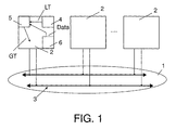
- FIG. 1 An exemplary embodiment of the communication network 1 according to the invention is shown in FIG. 1 shown.
- This communication network 1 can e.g. one from the magazine “Electronics", No. 14, 1999, pages 36 to 43 (Dr. Stefan Polenda, Georg Kroiss: "TTP: “Drive by Wire” within reach ”) known TTP protocol and exists from several network nodes 2, their access to a common communication medium 3, is regulated by a TDMA procedure (Time Division Multiple Access).
- the method ensures that only one network node 2 is connected to a predetermined one Time to send a message.
- a time-controlled protocol like the TTP protocol uses a local clock LT in each network node 2, which is used in a clock generator 4 of the network node 2 is generated.
- the local clock LT becomes too with other nodes a global match, a global clock GT, in a synchronization circuit 5 synchronized.
- a decoder 6 supplies the clock generator for synchronization 4, the synchronization circuit 5 for the node from the communication medium 3 specific dates.
- the synchronization circuit 5 is described in more detail in FIG. 2. She gets the local one Clock LT and a correction term KT to in a divider control 7 and a divider arrangement 8 to modify the local clock signal LT with a prescaler arrangement 9 and thereby delay or advance the next pulse for the global clock GT.
- the correction term KT arises in a comparison circuit 10 and results from the Comparison of the theoretical point in time at which a certain message (data) arrives should, with the actual time of receipt of this message (data) (see journal "Electronics", No. 14, 1999, pages 36 to 43, Dr. Stefan Polenda, Georg Kroiss: "TTP:” Drive by Wire "within reach”).
- Fig. 3 shows an embodiment of the divider control 7 and the divider arrangement 8.
- Die Divider control 7 contains a circuit for threshold value formation 11, the input of which the comparison circuit 10 and its output are connected to a control unit 12.
- the control unit 12 can send control signals to a divider factor generator 13, a calibration unit 14 or a modification device 15 send.
- the divider factor generator 13 and the calibration unit 14 is the comparison circuit of the Correction term KT and the divider arrangement 9 supplied two divider factors.
- Both the divider factor generator 13 and the calibration unit 14 can store data send to the prescaler arrangement 9. This is located together with the modification device 15 and a counter arrangement 16 in the divider arrangement 8 and sends the current divider factors to the counter arrangement 16, which are not only the global ones Clock GT provides, but also a control signal for modification to the Modification device 15 provides. This has a connection to the comparison circuit 10 and the clock generator 4 of the network node. The output of the modification device 15 leads to the counter arrangement 16.
- the control unit 12 sends in circuit for threshold value formation 11 Control signal to the modification device 15.
- the modification device 15 finds a modification of the local clock LT depending on the correction term KT instead of.
- An auxiliary signal HS resulting from the modification device 15 is indicated by divided down a counter array 16.
- Exceeds the determined correction term KT the predetermined first threshold value then the control unit 12 sends a control signal a divider factor generator 13, which changes the divider factors in a prescaler arrangement 9 depending on the correction term KT. If this correction term also exceeds a second threshold value that is greater than the first the control unit 12 sends a control signal to the calibration unit 14.
- the calibration unit 14 determines new values of the divisor factors depending on the correction term KT for the prescaler arrangement 9.
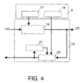
- the prescaler arrangement 9 shown in FIG. 4 has an integer prescaler factor 17 and additionally a non-integer prescaler factor 18.
- a method for handling non-integer prescaler factors is from the publication "A Synchronization Strategy for a time-triggered Multicluster Real-Time system "(Hermann Kopetz, Andreas Krüger, Dietmar Millinger, Anton Schedl, Proc. of the 14 th IEEE Symposium on Reliable Distributed Systems, Bad Neuenahr, Germany, IEEE Press, September 1995) known .
- a counter 19, an adder 20 and an accumulator register 21 form the counter arrangement 16.
- the output of the integer prescaler factor 17 leads to the counter 19 and the output of the non-integer prescaler factor 18 to the adder 20.
- the adder 20 not only sends its data to the modification device 15 but also to an accumulator register 21, which in turn transmits its result to the adder 20. Together, the adder 20 and the accumulator register 21 form an accumulator.
- the counter 19 is initialized with the value of the integer prescaler factor. This counter 19 reduces its content when a pulse of the auxiliary signal HS is received from the modification device 15. When the counter has reached zero, it generates the global clock GT.
- the non-integer prescaler is summed in the accumulator register 21 by the adder 20 until its sum reaches the overflow value (value 1).
- the adder 20 signals the modification device 15 to suppress a pulse of the local clock LT. In this way, the clocking of the counter 19 and thus also of the global clock GT is delayed.
- FIG. 5 shows the local clock LT, the modified auxiliary signal HS and the global clock GT.
- This illustration illustrates the dependency between the global clock GT and the local clock LT of a network node.
- the influence of the divisor factors is shown here using an example configuration.
- the integer prescaler was chosen to be 8, with the non-integer prescaler set to 1/3. Every third period of a global clock is extended by one clock period of a local clock. For this purpose, a pulse is hidden from the local clock at the appropriate time.
- the modified auxiliary signal HS serves as a counter clock to generate the global clock GT. 6 and FIG.
- FIG. 7 show, by way of example for a given local clock LT, the global clock signal GT1 generated in a conventional synchronization with auxiliary signal HS1 and the global clock signal GT2 generated with the aid of the dynamic configuration of the divider factors with auxiliary signal HS2.
- FIG. 6 describes the case of clock acceleration
- FIG. 7 shows the case of clock deceleration.
- the identity of the global clocks GT1 and GT2 can be clearly seen in both cases, while the auxiliary signals on the one hand represent the correction according to the conventional method (HS1) and the inventive dynamic divider factor correction (HS2).
Abstract
Die Erfindung bezieht sich auf ein Kommunikationsnetzwerk (1) mit mehreren Netzwerkknoten (2), die jeweils mit einer Synchronisationsschaltung (5) zur Erzeugung eines globalen Taktsignals (GT) aus einem von einem Taktgenerator (4) gebildeten lokalen Taktsignal (LT) in Abhängigkeit von einem Empfangszeitpunkt einer Nachricht versehen sind. Die Synchronisationsschaltung (5) enthält eine Teileranordnung (8) zur Teilung des lokalen Taktsignals (LT) in Abhängigkeit von einem Korrekturterm KT und mindestens einem Teilerfaktor, den eine Vorteileranordnung (9) liefert. Die Vergleichsschaltung (10) ist zur Bildung des Korrekturterms durch Vergleich des Empfangszeitpunkts einer Nachricht und des lokalen Taktsignals LT vorgesehen. Weiterhin enthält die Synchronisationsschaltung (5) eine Teilersteuerung (7), die eine Veränderung wenigstens eines Teilerfaktors bei Überschreiten des Korrekturterms (KT) über einen vorgegebenen ersten Schwellwert bewirken kann. <IMAGE>The invention relates to a communication network (1) with a plurality of network nodes (2), each with a synchronization circuit (5) for generating a global clock signal (GT) from a local clock signal (LT) formed by a clock generator (4) as a function of are provided with a time of receipt of a message. The synchronization circuit (5) contains a divider arrangement (8) for dividing the local clock signal (LT) as a function of a correction term KT and at least one divider factor, which a prescaler arrangement (9) provides. The comparison circuit (10) is provided to form the correction term by comparing the time of reception of a message and the local clock signal LT. The synchronization circuit (5) also contains a divider control (7), which can cause a change in at least one divider factor when the correction term (KT) is exceeded above a predetermined first threshold value. <IMAGE>
Description
Die Erfindung bezieht sich auf ein Kommunikationsnetzwerk mit mehreren Netzwerkknoten, die jeweils
- mit einer Synchronisationsschaltung zur Erzeugung eines globalen Taktsignals aus einem von einem Taktgenerator gebildeten lokalen Taktsignal in Abhängigkeit von einem Empfangszeitpunkt einer Nachricht
- mit einer in der Synchronisationsschaltung enthaltener Teileranordnung zur Teilung des lokalen Taktsignals in Abhängigkeit von mindestens einem Teilerfaktor, den eine Vorteileranordnung liefert, und einem Korrekturterm, und
- einer Vergleichsschaltung zur Bildung des Korrekturterms durch Vergleich des Empfangszeitpunkts einer Nachricht und des lokalen Taktsignals LT versehen sind.
- with a synchronization circuit for generating a global clock signal from a local clock signal formed by a clock generator as a function of a time of reception of a message
- with a divider arrangement contained in the synchronization circuit for dividing the local clock signal as a function of at least one divider factor, which a prescaler arrangement provides, and a correction term, and
- a comparison circuit for forming the correction term by comparing the time of reception of a message and the local clock signal LT are provided.
In einem solchen Kommunikationsnetzwerk für die Kraftfahrzeugtechnik kann z.B. das aus der Zeitschrift "Elektronik", Nr. 14, 1999, Seite 36 bis 43 (Dr. Stefan Polenda, Georg Kroiss: "TTP: "Drive by Wire" in greifbarer Nähe") bekannte TTP-Protokoll (TTP = Time-Triggered Protocol) verwendet werden. Dieses Protokoll stellt einen Korrekturterm für die Durchführung der Synchronisation zur Verfügung, der sich aus dem Vergleich des theoretischen Zeitpunktes, zu dem eine bestimmte Nachricht eintreffen soll, mit dem tatsächlichen Empfangszeitpunkt ergibt. Falls dieser Korrekturterm durch eine schleichende, kontinuierliche Abweichung (z.B. durch Alterung der Taktquelle) verursacht wird, muss er immer wieder in jedem Synchronisationsintervall ausgeglichen werden.In such a communication network for automotive engineering, e.g. the from the magazine "Electronics", No. 14, 1999, pages 36 to 43 (Dr. Stefan Polenda, Georg Kroiss: "TTP:" Drive by Wire "within reach") known TTP protocol (TTP = Time-Triggered Protocol) can be used. This protocol provides a correction term available for the implementation of the synchronization, which results from the comparison of the theoretical point in time at which a certain message should arrive with the actual reception time. If this correction term is caused by a creeping, continuous deviation (e.g. caused by aging of the clock source), it must be balanced again and again in every synchronization interval.
Der Erfindung liegt die Aufgabe zugrunde, ein Kommunikationsnetzwerk mit dynamischer Synchronisation zu schaffen.The invention has for its object a communication network with dynamic To create synchronization.
Die Aufgabe wird durch ein Kommunikationsnetzwerk der eingangs genannten Art dadurch gelöst, dass die Synchronisationsschaltung eine Teilersteuerung enthält, die zur Ver änderung wenigstens eines Teilerfaktors bei Überschreiten des Korrekturterms über einen vorgegebenen ersten Schwellwert vorgesehen ist.The task is achieved through a communication network of the type mentioned solved that the synchronization circuit contains a divider control, which is used for ver Change at least one divisor factor when the correction term is exceeded by one predetermined first threshold value is provided.
Die dieser Erfindung zugrundeliegende Idee ist eine Synchronisationsschaltung, die durch eine Teilersteuerung eine dynamische Konfiguration der Teilerfaktoren bei Überschreiten des in der Vergleichsschaltung erzeugten Korrekturterms über einen vorgegebenen ersten Schwellwert bewirkt. Auf diese Weise wird eine kontinuierliche Abweichung des lokalen Taktes von dem globalen Takt durch eine einmalige Änderung der Teilerfaktoren berücksichtigt, und eine mehrfache Nachführung zum Ausgleich der festgestellten Abweichung des lokalen Taktes wird überflüssig.The idea on which this invention is based is a synchronization circuit which is implemented by a divider control dynamic configuration of the divider factors when exceeded of the correction term generated in the comparison circuit via a predetermined first Threshold causes. This way there is a continuous deviation of the local Clock from the global clock is taken into account by changing the divider factors once, and multiple tracking to compensate for the deviation found the local clock becomes superfluous.
Um die Änderung der Teilerfaktoren zu bewirken, wird ein Korrekturterm gebildet. Bei Überschreiten des Korrekturterms über den vorgegebenen ersten Schwellwert liefert die Steuereinheit an einen in der Teilersteuerung enthaltenen Teilerfaktorengenerator ein Steuersignal. Daraufhin führt der Teilerfaktorengenerator eine Teileranpassung durch.A correction term is formed in order to change the divisor factors. At If the correction term is exceeded above the predetermined first threshold value, the Control unit to a divider factor generator contained in the divider control Control signal. The divider factor generator then performs a divider adjustment.
Falls der Korrekturterm nicht nur den ersten sondern auch einen zweiten Schwellwert, der größer als der erste ist, überschreitet, wird eine Kalibrierung der Teilerfaktoren in der Kalibrierungseinheit durchgeführt. Damit ist es möglich, auch große Abweichungen des lokalen Taktes, wie sie z.B. nach Betriebspausen von Teilen des Kommunikationssystems auftreten können, dauerhaft zu korrigieren.If the correction term not only the first but also a second threshold, the is greater than the first, a calibration of the divider factors in the calibration unit carried out. This makes it possible to also see large deviations from the local one Clock as e.g. occur after breaks in operation of parts of the communication system can correct permanently.
Anhand einiger Ausführungsbeispiele soll die Erfindung in Verbindung mit den Figuren näher erläutert werden. Es zeigen:
- Fig. 1
- ein Kommunikationsnetzwerk mit mehreren Netzwerkknoten,
- Fig. 2
- eine Synchronisationsschaltung eines Netzwerkknotens,
- Fig. 3
- eine Teileranordnung und eine Teilersteuerung einer Synchronisationsschaltung,
- Fig. 4
- eine Vorteileranordnung und eine Zähleranordnung einer Teileranordnung und
- Fig. 5 bis 7
- eine Signaldarstellung der in dem Kommunikationssystem auftretender Takte.
- Fig. 1
- a communication network with several network nodes,
- Fig. 2
- a synchronization circuit of a network node,
- Fig. 3
- a divider arrangement and a divider control of a synchronization circuit,
- Fig. 4
- a prescaler arrangement and a counter arrangement of a divider arrangement and
- 5 to 7
- a signal representation of the clocks occurring in the communication system.
Ein Ausführungsbeispiel des erfindungsgemäßen Kommunikationsnetzwerks 1 ist in Fig. 1
dargestellt. Dieses Kommunikationsnetzwerk 1 kann z.B. ein aus der Zeitschrift
"Elektronik", Nr. 14, 1999, Seite 36 bis 43 (Dr. Stefan Polenda, Georg Kroiss: "TTP:
"Drive by Wire" in greifbarer Nähe") bekanntes TTP-Protokoll verwenden und besteht
aus mehreren Netzwerkknoten 2, deren Zugriff auf ein gemeinsames Kommunikationsmedium
3, durch ein TDMA-Verfahren (Time Division Multiple Access) geregelt wird.
Das Verfahren gewährleistet, dass immer nur ein Netzknoten 2 zu einer vorbestimmten
Zeit eine Nachricht versenden darf. Ein zeitgesteuertes Protokoll wie das TTP-Protokoll
benutzt in jedem Netzwerkknoten 2 einen lokalen Takt LT, der in einem Taktgenerator 4
des Netzwerkknotens 2 erzeugt wird. Der lokale Takt LT wird mit anderen Knoten zu
einer globalen Übereinstimmung, einem globalen Takt GT, in einer Synchronisationsschaltung
5 synchronisiert. Zur Synchronisation liefert ein Dekodierer 6 dem Taktgenerator
4, der Synchronisationsschaltung 5 die für den Knoten aus dem Kommunikationsmedium
3 bestimmten Daten.An exemplary embodiment of the
Die Synchronisationsschaltung 5 wird in Fig. 2 näher beschrieben. Sie erhält den lokalen
Takt LT und einen Korrekturterm KT, um in einer Teilersteuerung 7 und einer Teileranordnung
8 mit einer Vorteileranordnung 9 das lokale Taktsignal LT zu modifizieren
und dadurch den nächsten Puls für den globalen Takt GT zu verzögern oder vorzuziehen.
Der Korrekturterm KT entsteht in einer Vergleichsschaltung 10 und ergibt sich aus dem
Vergleich des theoretischen Zeitpunktes, zu dem eine bestimmte Nachricht (Data) eintreffen
soll, mit dem tatsächlichen Empfangszeitpunkt dieser Nachricht (Data) (vgl. Zeitschrift
"Elektronik", Nr. 14, 1999, Seite 36 bis 43, Dr. Stefan Polenda, Georg Kroiss:
"TTP: "Drive by Wire" in greifbarer Nähe").The
Fig. 3 zeigt ein Ausführungsbeispiel der Teilersteuerung 7 und der Teileranordnung 8. Die
Teilersteuerung 7 enthält eine Schaltung zur Schwellwertbildung 11, deren Eingang mit
der Vergleichsschaltung 10 und deren Ausgang mit einer Steuereinheit 12 verbunden sind.
Die Steuereinheit 12 kann Steuersignale zu einem Teilerfaktorengenerator 13, einer Kalibrierungseinheit
14 oder einer Modifikationsvorrichtung 15 schicken. Dem Teilerfaktorengenerator
13 und der Kalibrierungseinheit 14 wird von der Vergleichsschaltung der
Korrekturterm KT und von dem Vorteileranordnung 9 zwei Teilerfaktoren geliefert. Fig. 3 shows an embodiment of the
Sowohl der Teilerfaktorengenerator 13 als auch die Kalibrierungseinheit 14 können Daten
an die Vorteileranordnung 9 senden. Diese befindet sich zusammen mit der Modifikationsvorrichtung
15 und einer Zähleranordnung 16 in der Teileranordnung 8 und schickt
jeweils die aktuellen Teilerfaktoren an die Zähleranordnung 16, die nicht nur den globalen
Takt GT zur Verfügung stellt, sondern auch ein Steuersignal zur Modifizierung an die
Modifikationsvorrichtung 15 liefert. Diese hat eine Verbindung zur Vergleichsschaltung
10 und den Taktgenerator 4 des Netzwerkknotens. Der Ausgang der Modifikationsvorrichtung
15 führt zur der Zähleranordnung 16.Both the
In Synchronisationsintervallen wird die Abweichung des lokalen Taktsignals LT von dem
globalen Taktsignal GT in der Vergleichsschaltung 10 anhand des Korrekturterms KT
festgestellt. Falls der Korrekturterm KT einen vorgegebenen ersten Schwellwert in der
Schaltung zur Schwellwertbildung 11 unterschreitet, sendet die Steuereinheit 12 ein
Steuersignal an die Modifikationsvorrichtung 15. In der Modifikationsvorrichtung 15
findet eine Modifikation des lokalen Takts LT in Abhängigkeit des Korrekturterms KT
statt. Ein sich aus der Modifikationsvorrichtung 15 ergebenes Hilfssignal HS wird durch
eine Zähleranordnung 16 heruntergeteilt. Überschreitet der festgestellte Korrekturterm KT
den vorgegebenen ersten Schwellwert, dann sendet die Steuereinheit 12 ein Steuersignal an
einen Teilerfaktorengenerator 13, der eine Veränderung der Teilerfaktoren in einer Vorteileranordnung
9 in Abhängigkeit des Korrekturterms KT bewirkt. Falls dieser Korrekturterm
auch einen zweiten Schwellwert, der größer als der erste ist, überschreitet, sendet
die Steuereinheit 12 ein Steuersignal an die Kalibrierungseinheit 14. Die Kalibrierungseinheit
14 bestimmt in Abhängigkeit vom Korrekturterm KT neue Werte der Teilerfaktoren
für die Vorteileranordnung 9.At synchronization intervals, the deviation of the local clock signal LT from that
global clock signal GT in the
Um für den lokalen Taktgenerator keine Einschränkung bezüglich der Grundfrequenz
vorzuschreiben, verfügt die in Fig. 4 dargestellte Vorteileranordnung 9 über einen ganzzahligen
Vorteilerfaktor 17 und zusätzlich über einen nicht ganzzahligen Vorteilerfaktor
18. Ein Verfahren zur Handhabung nicht ganzzahliger Vorteilerfaktoren ist aus der Veröffentlichung
"A Synchronization Strategy for a Time-Triggered Multicluster Real-Time
System" (Hermann Kopetz, Andreas Krüger, Dietmar Millinger, Anton Schedl; Proc. of
the 14th IEEE Symposium on Reliable Distributed Systems, Bad Neuenahr, Germany,
IEEE Press, Sep. 1995) bekannt. Ein Zähler 19, ein Addierer 20 und ein Akkumulatorregister
21 bilden die Zähleranordnung 16. Der Ausgang des ganzzahligen Vorteilerfaktors
17 führt zu dem Zähler 19 und der Ausgang des nicht ganzzahligen Vorteilerfaktor 18 zu
dem Addierer 20. Der Addierer 20 schickt seine Daten nicht nur zur Modifikationsvorrichtung
15 sondern auch zu einem Akkumulatorregister 21, das wiederum
sein Ergebnis dem Addierer 20 übermittelt. Zusammen bilden der Addierer 20 und das
Akkumulatorregister 21 einen Akkumulator. In der Zähleranordnung 16 wird der Zähler
19 mit dem Wert des ganzzahligen Vorteilerfaktors initialisiert. Dieser Zähler 19 reduziert
seinen Inhalt beim Empfang eines Pulses des Hilfssignals HS aus der Modifikationsvorrichtung
15. Wenn der Zähler den Wert Null erreicht hat, erzeugt er den globalen Takt
GT. Gleichzeitig wird der nicht ganzzahlige Vorteiler durch den Addierer 20 in dem
Akkumulatorregister 21 summiert, bis seine Summe den Überlaufwert (Wert 1) erreicht.
In diesem Moment signalisiert der Addierer 20 der Modifikationsvorrichtung 15 einen
Puls des lokalen Taktes LT zu unterdrücken. Auf diese Weise wird die Taktung des Zählers
19 und somit auch des globalen Taktes GT verzögert.In order not to impose a restriction on the fundamental frequency for the local clock generator, the
Fig. 5 zeigt den lokalen Takt LT, das modifizierte Hilfssignal HS und den globalen Takt
GT. Diese Darstellung verdeutlicht die Abhängigkeit zwischen dem globalen Takt GT und
dem lokalen Takt LT eines Netzwerkknotens. Der Einfluss der Teilerfaktoren ist hier anhand
einer Beispielkonfiguration dargestellt. Der ganzzahlige Vorteiler ist zu 8 gewählt
worden, wobei der nicht ganzzahlige Vorteiler auf 1/3 gesetzt wurde. Jede dritte Periode
eines globalen Takts wird um eine Taktperiode eines lokalen Takts verlängert. Dazu wird
aus dem lokalen Takt zum entsprechenden Zeitpunkt ein Puls ausgeblendet. Das modifizierte
Hilfssignal HS dient als Zählertakt, um den globalen Takt GT zu generieren.
Fig. 6 und Fig. 7 zeigen beispielhaft für einen gegebenen lokalen Takt LT jeweils das in
herkömmlicher Synchronisation erzeugte globale Taktsignal GT1 mit Hilfssignal HS1
sowie das mithilfe der dynamischen Konfiguration der Teilerfaktoren erzeugte globale
Taktsignal GT2 mit Hilfssignal HS2. Fig. 6 beschreibt dabei den Fall der Taktbeschleunigung,
während Fig. 7 den Fall der Taktverzögerung darstellt. Man erkennt deutlich in
beiden Fällen die Identität der globalen Takte GT1 und GT2, während die Hilfssignale
zum einen die Korrektur nach herkömmlichem Verfahren (HS1) und die erfindungsgemäße,
dynamische Teilerfaktorenkorrektur (HS2) darstellen. Am Beispiel der Taktbeschleunigung
soll der Vorgang weiter verdeutlicht werden: Während das Signal HS1 in
jedem globalen Takt GT1 einen zusätzlichen Puls aufweist, um die acht Pulse in einem
verkürzten Zeitraum zu erzeugen, genügen bei HS2 durch die veränderten Teilerfaktoren
sieben Pulse, um den Beginn einer neuen globalen Taktperiode anzuzeigen.5 shows the local clock LT, the modified auxiliary signal HS and the global clock GT. This illustration illustrates the dependency between the global clock GT and the local clock LT of a network node. The influence of the divisor factors is shown here using an example configuration. The integer prescaler was chosen to be 8, with the non-integer prescaler set to 1/3. Every third period of a global clock is extended by one clock period of a local clock. For this purpose, a pulse is hidden from the local clock at the appropriate time. The modified auxiliary signal HS serves as a counter clock to generate the global clock GT.
6 and FIG. 7 show, by way of example for a given local clock LT, the global clock signal GT1 generated in a conventional synchronization with auxiliary signal HS1 and the global clock signal GT2 generated with the aid of the dynamic configuration of the divider factors with auxiliary signal HS2. FIG. 6 describes the case of clock acceleration, while FIG. 7 shows the case of clock deceleration. The identity of the global clocks GT1 and GT2 can be clearly seen in both cases, while the auxiliary signals on the one hand represent the correction according to the conventional method (HS1) and the inventive dynamic divider factor correction (HS2). The process should be further illustrated using the example of clock acceleration: While the signal HS1 has an additional pulse in each global clock GT1 to generate the eight pulses in a shortened period of time, with HS2 the changed divider factors suffice for seven pulses to start one display new global clock period.
Claims (3)
dass die Synchronisationsschaltung (5) eine Teilersteuerung (7) enthält, die zur Veränderung wenigstens eines Teilerfaktors bei Überschreiten des Korrekturterms KT über einen vorgegebenen ersten Schwellwert vorgesehen ist.Communication network (1)
that the synchronization circuit (5) contains a divider control (7) which is provided for changing at least one divider factor when the correction term KT is exceeded above a predetermined first threshold value.
dadurch gekennzeichnet,
dass die Teilersteuerung (7) eine Steuereinheit (12) enthält, welche zur Lieferung eines Steuersignals an einen in der Teilersteuerung (7) enthaltenen Teilerfaktorengenerator (13) bei Überschreiten des Korrekturterms über den vorgegebenen ersten Schwellwert vorgesehen ist, und dass der Teilerfaktorengenerator (13) bei Vorliegen des Steuersignals zur Änderung der Teilerfaktoren vorgesehen ist. Communication network according to claim 1,
characterized,
that the divider control (7) contains a control unit (12) which is provided for supplying a control signal to a divider factor generator (13) contained in the divider control (7) when the correction term is exceeded above the predetermined first threshold value, and that the divider factor generator (13) if the control signal is present, the divider factors are changed.
dadurch gekennzeichnet,
dass die Synchronisationsschaltung eine Kalibrierungseinheit (14) enthält, die zur Kalibrierung der Teilerfaktoren bei Überschreiten des Korrekturterms KT über einen vorgegebenen zweiten Schwellwert, der größer als der erste Schwellwert ist, vorgesehen ist.Communication network according to claim 2,
characterized,
that the synchronization circuit contains a calibration unit (14) which is provided for calibrating the divider factors when the correction term KT is exceeded above a predetermined second threshold value which is greater than the first threshold value.
Applications Claiming Priority (2)
| Application Number | Priority Date | Filing Date | Title |
|---|---|---|---|
| DE10007070A DE10007070A1 (en) | 2000-02-16 | 2000-02-16 | Communication network with time-controlled communication protocol |
| DE10007070 | 2000-02-16 |
Publications (3)
| Publication Number | Publication Date |
|---|---|
| EP1126645A2 true EP1126645A2 (en) | 2001-08-22 |
| EP1126645A3 EP1126645A3 (en) | 2005-09-14 |
| EP1126645B1 EP1126645B1 (en) | 2008-07-09 |
Family
ID=7631205
Family Applications (1)
| Application Number | Title | Priority Date | Filing Date |
|---|---|---|---|
| EP01200492A Expired - Lifetime EP1126645B1 (en) | 2000-02-16 | 2001-02-09 | Communication network with time controlled communication protocole |
Country Status (4)
| Country | Link |
|---|---|
| US (1) | US6917656B2 (en) |
| EP (1) | EP1126645B1 (en) |
| JP (1) | JP2001251282A (en) |
| DE (2) | DE10007070A1 (en) |
Families Citing this family (5)
| Publication number | Priority date | Publication date | Assignee | Title |
|---|---|---|---|---|
| DE10147422A1 (en) | 2001-09-26 | 2003-04-24 | Siemens Ag | Communication system and method for synchronizing a communication cycle |
| EP1335520B1 (en) * | 2002-02-11 | 2018-05-30 | Semiconductor Components Industries, LLC | Multiplex bus system with duty cycle correction |
| DE10347381B4 (en) | 2003-10-08 | 2019-05-09 | Volkswagen Ag | Method and device for the error-protected transmission of user data |
| US7424076B2 (en) * | 2004-01-22 | 2008-09-09 | Nokia Corporation | System and method for providing synchronization information to a receiver |
| DE102004006398B4 (en) * | 2004-02-10 | 2006-06-08 | Atmel Germany Gmbh | Method and device for synchronizing a functional unit to a predetermined clock frequency |
Family Cites Families (4)
| Publication number | Priority date | Publication date | Assignee | Title |
|---|---|---|---|---|
| US4939753A (en) * | 1989-02-24 | 1990-07-03 | Rosemount Inc. | Time synchronization of control networks |
| EP0718995A1 (en) * | 1994-12-20 | 1996-06-26 | International Business Machines Corporation | Apparatus and method for synchronizing clock signals for digital links in a packet switching mode |
| WO1999007077A2 (en) * | 1997-07-31 | 1999-02-11 | Stanford Syncom Inc. | Means and method for a synchronous network communications system |
| DE19849458A1 (en) * | 1998-10-28 | 2000-05-04 | Philips Corp Intellectual Pty | Wireless network with clock synchronization |
-
2000
- 2000-02-16 DE DE10007070A patent/DE10007070A1/en not_active Withdrawn
-
2001
- 2001-02-09 DE DE50114081T patent/DE50114081D1/en not_active Expired - Lifetime
- 2001-02-09 EP EP01200492A patent/EP1126645B1/en not_active Expired - Lifetime
- 2001-02-12 US US09/781,504 patent/US6917656B2/en not_active Expired - Lifetime
- 2001-02-13 JP JP2001035631A patent/JP2001251282A/en not_active Withdrawn
Non-Patent Citations (2)
| Title |
|---|
| KOPETZ H ET AL: "A Synchronization Strategy for Time-Triggered Multicluster Real-Time System" RELIABLE DISTRIBUTED SYSTEMS. BAD NEUENAHR, SEPT. 13 - 15, 1995, NEW YORK, IEEE, US, 13. September 1995 (1995-09-13), Seiten 154-161, XP002293492 * |
| POLEDNA S ET AL: "TTP: DRIVE BY WIRE IN GREIFBARER NAEHE ECHTZEIT-KOMMUNIKATION IM AUTOMOBIL MIT ZEITGESTEUERTEM PROTOKOLL ERLAUBT HOCHZUVERLAESSIGE ANWENDUNGEN" ELEKTRONIK, WEKA FACHZEITSCR.-VERLAG, MUNCHEN, DE, Bd. 48, Nr. 14, 13. Juli 1999 (1999-07-13), Seite 36-38,40,42,43, XP000913186 ISSN: 0013-5658 * |
Also Published As
| Publication number | Publication date |
|---|---|
| US6917656B2 (en) | 2005-07-12 |
| DE50114081D1 (en) | 2008-08-21 |
| DE10007070A1 (en) | 2001-08-30 |
| US20020052707A1 (en) | 2002-05-02 |
| EP1126645A3 (en) | 2005-09-14 |
| EP1126645B1 (en) | 2008-07-09 |
| JP2001251282A (en) | 2001-09-14 |
Similar Documents
| Publication | Publication Date | Title |
|---|---|---|
| DE3244327C2 (en) | Circuit for generating a substrate bias | |
| DE4342266A1 (en) | Clock generator and phase comparator for use in such a clock generator | |
| DE10320794B3 (en) | Clock signal pulse ratio correction device for semiconductor memory compares pulse ratio of corrected clock signal and corrected complementary clock signal with required pulse ratio for adjustment of correction delay | |
| DE2216123A1 (en) | Procedure and arrangement for analog-to-digital implementation with multiple integration | |
| DE3212453C2 (en) | ||
| DE2648560C2 (en) | Synchronization of clock signals with input signals | |
| EP0023331B1 (en) | Circuit arrangement for the synchronization of a subordinate device, in particular a digital subscriber station, by a higher order device, in particular a digital switching exchange of a pcm telecommunication network | |
| DE2119091A1 (en) | Voltage controlled clock generator | |
| EP1126645B1 (en) | Communication network with time controlled communication protocole | |
| DE3315372C2 (en) | ||
| EP0128396A1 (en) | Integrated bus-oriented communication system | |
| DE2658908B2 (en) | Electronic clock | |
| DE2805959C2 (en) | Electronic clock | |
| DE3920391A1 (en) | CIRCUIT ARRANGEMENT FOR ADJUSTING THE BITRATES OF TWO SIGNALS | |
| DE3743434A1 (en) | TIME SIGNALER | |
| EP0180001A2 (en) | Circuit for temporarily storing digital signals | |
| EP0237699B1 (en) | Method and circuit arrangement for the synchronization of a voltage-controlled oscillator inherent to a central exchange | |
| DE1256689C2 (en) | CLOCK GENERATOR WITH A DEVICE FOR SWITCHING OFF AND REACTIVATING THE CYCLE SIGNALS FROM ELECTRONIC DATA PROCESSING SYSTEMS IN THE CORRECT PHASE | |
| DE19739245C2 (en) | Digital circuit with a filter unit to suppress interference pulses | |
| DE2840853A1 (en) | DATA PULSE RECEIVING ARRANGEMENT | |
| DE10056164C1 (en) | Circuit arrangement for generating clock signals which are edge-synchronous with output signals of a clock generator for a semiconductor memory | |
| EP0053650B1 (en) | Monolithic integrated television receiver vertical deflection circuit with digital tangent-corrected line frequency signal processing | |
| DE2935353C2 (en) | ||
| DE2058958C3 (en) | Circuit to reduce the influence of interference pulses on correction pulses, which cause the synchronization of data with clock pulses | |
| WO1998049802A1 (en) | Programmable phase adjustment |
Legal Events
| Date | Code | Title | Description |
|---|---|---|---|
| PUAI | Public reference made under article 153(3) epc to a published international application that has entered the european phase |
Free format text: ORIGINAL CODE: 0009012 |
|
| AK | Designated contracting states |
Kind code of ref document: A2 Designated state(s): AT BE CH CY DE DK ES FI FR GB GR IE IT LI LU MC NL PT SE TR |
|
| AX | Request for extension of the european patent |
Free format text: AL;LT;LV;MK;RO;SI |
|
| RAP1 | Party data changed (applicant data changed or rights of an application transferred) |
Owner name: PHILIPS CORPORATE INTELLECTUAL PROPERTY GMBH Owner name: KONINKLIJKE PHILIPS ELECTRONICS N.V. |
|
| RAP1 | Party data changed (applicant data changed or rights of an application transferred) |
Owner name: PHILIPS INTELLECTUAL PROPERTY & STANDARDS GMBH Owner name: KONINKLIJKE PHILIPS ELECTRONICS N.V. |
|
| PUAL | Search report despatched |
Free format text: ORIGINAL CODE: 0009013 |
|
| AK | Designated contracting states |
Kind code of ref document: A3 Designated state(s): AT BE CH CY DE DK ES FI FR GB GR IE IT LI LU MC NL PT SE TR |
|
| AX | Request for extension of the european patent |
Extension state: AL LT LV MK RO SI |
|
| RAP1 | Party data changed (applicant data changed or rights of an application transferred) |
Owner name: KONINKLIJKE PHILIPS ELECTRONICS N.V. Owner name: PHILIPS INTELLECTUAL PROPERTY & STANDARDS GMBH |
|
| 17P | Request for examination filed |
Effective date: 20060314 |
|
| AKX | Designation fees paid |
Designated state(s): DE FR GB |
|
| RAP1 | Party data changed (applicant data changed or rights of an application transferred) |
Owner name: NXP B.V. |
|
| 17Q | First examination report despatched |
Effective date: 20071002 |
|
| GRAP | Despatch of communication of intention to grant a patent |
Free format text: ORIGINAL CODE: EPIDOSNIGR1 |
|
| GRAS | Grant fee paid |
Free format text: ORIGINAL CODE: EPIDOSNIGR3 |
|
| GRAA | (expected) grant |
Free format text: ORIGINAL CODE: 0009210 |
|
| AK | Designated contracting states |
Kind code of ref document: B1 Designated state(s): DE FR GB |
|
| REG | Reference to a national code |
Ref country code: GB Ref legal event code: FG4D Free format text: NOT ENGLISH |
|
| REF | Corresponds to: |
Ref document number: 50114081 Country of ref document: DE Date of ref document: 20080821 Kind code of ref document: P |
|
| PLBE | No opposition filed within time limit |
Free format text: ORIGINAL CODE: 0009261 |
|
| STAA | Information on the status of an ep patent application or granted ep patent |
Free format text: STATUS: NO OPPOSITION FILED WITHIN TIME LIMIT |
|
| 26N | No opposition filed |
Effective date: 20090414 |
|
| PGFP | Annual fee paid to national office [announced via postgrant information from national office to epo] |
Ref country code: DE Payment date: 20100219 Year of fee payment: 10 |
|
| REG | Reference to a national code |
Ref country code: DE Ref legal event code: R119 Ref document number: 50114081 Country of ref document: DE Effective date: 20110901 |
|
| PG25 | Lapsed in a contracting state [announced via postgrant information from national office to epo] |
Ref country code: DE Free format text: LAPSE BECAUSE OF NON-PAYMENT OF DUE FEES Effective date: 20110901 |
|
| REG | Reference to a national code |
Ref country code: FR Ref legal event code: PLFP Year of fee payment: 16 |
|
| REG | Reference to a national code |
Ref country code: FR Ref legal event code: PLFP Year of fee payment: 17 |
|
| REG | Reference to a national code |
Ref country code: FR Ref legal event code: PLFP Year of fee payment: 18 |
|
| PGFP | Annual fee paid to national office [announced via postgrant information from national office to epo] |
Ref country code: GB Payment date: 20200123 Year of fee payment: 20 |
|
| PGFP | Annual fee paid to national office [announced via postgrant information from national office to epo] |
Ref country code: FR Payment date: 20200122 Year of fee payment: 20 |
|
| REG | Reference to a national code |
Ref country code: GB Ref legal event code: PE20 Expiry date: 20210208 |
|
| PG25 | Lapsed in a contracting state [announced via postgrant information from national office to epo] |
Ref country code: GB Free format text: LAPSE BECAUSE OF EXPIRATION OF PROTECTION Effective date: 20210208 |