EP1126289A2 - Image acquisition method and apparatus - Google Patents
Image acquisition method and apparatus Download PDFInfo
- Publication number
- EP1126289A2 EP1126289A2 EP01102319A EP01102319A EP1126289A2 EP 1126289 A2 EP1126289 A2 EP 1126289A2 EP 01102319 A EP01102319 A EP 01102319A EP 01102319 A EP01102319 A EP 01102319A EP 1126289 A2 EP1126289 A2 EP 1126289A2
- Authority
- EP
- European Patent Office
- Prior art keywords
- image
- stripe pattern
- grid
- scattered ray
- sampling
- Prior art date
- Legal status (The legal status is an assumption and is not a legal conclusion. Google has not performed a legal analysis and makes no representation as to the accuracy of the status listed.)
- Granted
Links
Images



Classifications
-
- G—PHYSICS
- G01—MEASURING; TESTING
- G01T—MEASUREMENT OF NUCLEAR OR X-RADIATION
- G01T1/00—Measuring X-radiation, gamma radiation, corpuscular radiation, or cosmic radiation
- G01T1/29—Measurement performed on radiation beams, e.g. position or section of the beam; Measurement of spatial distribution of radiation
- G01T1/2914—Measurement of spatial distribution of radiation
- G01T1/2921—Static instruments for imaging the distribution of radioactivity in one or two dimensions; Radio-isotope cameras
- G01T1/2928—Static instruments for imaging the distribution of radioactivity in one or two dimensions; Radio-isotope cameras using solid state detectors
-
- A—HUMAN NECESSITIES
- A61—MEDICAL OR VETERINARY SCIENCE; HYGIENE
- A61B—DIAGNOSIS; SURGERY; IDENTIFICATION
- A61B6/00—Apparatus or devices for radiation diagnosis; Apparatus or devices for radiation diagnosis combined with radiation therapy equipment
- A61B6/52—Devices using data or image processing specially adapted for radiation diagnosis
- A61B6/5258—Devices using data or image processing specially adapted for radiation diagnosis involving detection or reduction of artifacts or noise
Definitions
- the present invention relates to an image acquisition technique and, more particularly, to an image acquisition apparatus for acquiring an image corresponding to an X-ray transmission distribution obtained on an object.
- X-ray intensity spatial distributions can be acquired as digital images.
- currently available schemes include a scheme of forming a latent image on a photostimulable phosphor by using X-ray energy and acquiring an image from a laser pumping light distribution, a scheme of converting an X-ray intensity distribution into a light intensity distribution (fluorescence), directly converting the distribution into an electrical signal by using a surface center having a plurality of pixels, and converting the signal into a digital image, and a scheme of directly converting an X-ray intensity distribution into a charge distribution.
- the digitization of X-ray images has the following merits:
- an optimal means is to use a scattered ray removing grid having many lead plates arranged in the same direction as in a conventional scheme using silver-halide films.
- Fig. 10 is a schematic sectional view of a structure using a grid.
- Reference numeral 81 denotes a point (X-ray focal point) of an X-ray tube from which X-rays are generated; 82, an object; 83, a grid; 84, an energy conversion unit for converting an X-ray intensity distribution into a light intensity or charge amount; and 85, a sensor unit for spatially sampling the distribution.
- Scattered X-rays reflected by the object reach the grid 83 as well as X-rays directly emitted from the X-ray tube. Most of the scattered X-rays are cut by the grid 83 made up of lead members facing the X-ray focal point 81.
- a drawback of the grid 83 is that it partly cuts direct X-rays while it cuts scattered X-rays.
- This cutting pattern corresponds to the arrangement of the lead members of the grid, and the image generally suffers a stripe pattern.
- An X-ray image has evolved into (1) an image formed by a film-screen system (analog image) ⁇ (2) a digital image formed by reading a latent image formed by a photostimulable phosphor by laser scanning ⁇ (3) an image formed by direct sampling (flat panel sensor) the two-dimensional spatial distribution of an X-ray dose in a two-dimensional space.
- Different measures have therefore been taken against a stripe pattern (grid image) on an image which originates from the lead members used for the grid 83.
- the means of moving the grid itself in (a) is effective in all cases of X-ray image acquisition.
- this means is-difficult to use because of an increase in cost due to, for example, a driving system for moving the grid, an increase in apparatus size, the relationship between the driving timing and the X-ray radiation timing, adjustment of the driving speed, and the like.
- the means of increasing the spatial frequency of the grid stripe pattern in (b) has its own limit. That is, when the frequency of the grid stripe pattern is set to a high spatial frequency at which no grid image is formed, since the thickness of each lead plate for blocking scattered rays is almost fixed, an area through which direct rays are transmitted narrows, and the use efficiency of the X-ray dose extremely decreases. As a consequence, imaging operation cannot be properly performed.
- a grid image can be removed by the general idea of using an anti-aliasing filter, i.e., performing sampling on the time axis after low-pass filtering in the state of an analog signal as this video signal.
- An anti-aliasing filter i.e., performing sampling on the time axis after low-pass filtering in the state of an analog signal as this video signal.
- a similar method is disclosed in Japanese Patent No. 2507659, in which a grid image and its frequency are obtained by Fourier transformation of an image obtained by preliminary sampling, and a low-pass filter corresponding to the result is selected to remove a grid image.
- sampling is performed on the time axis at intervals shorter than desired intervals instead of performing analog low-pass filtering to eliminate aliasing of grid stripe pattern information, and the resultant information is separated from image information. Thereafter, digital low-pass filtering is performed, and the resultant image is digitally decimated (sub-sampled), thereby obtaining an image at the desired sampling intervals.
- analog low-pass filtering is performed, and the resultant image is digitally decimated (sub-sampled), thereby obtaining an image at the desired sampling intervals.
- Japanese Patent Laid-Open No. 9-78970 and U.S. Patent No. 5,801,385 disclose methods of setting the grid lead member intervals to be smaller than the sampling pitch and equal to or near the width of the opening of a light-receiving portion of one pixel, thereby reducing the contrast of a grid stripe pattern.
- a grid image is input and stored under a plurality of conditions. When imaging operation is actually performed by using the grid, the obtained image is divided by a grid image of the stored grid images which corresponds to the condition under which the actual imaging operation is performed, thereby removing the grid image.
- the grid lead member intervals are required to be very small; 10 or more grid lead members per mm. If the intervals become so small, since the thickness of each lead plate for blocking scattered rays is almost fixed, the areas through which direct rays pass narrow, and the use efficiency of the X-ray dose becomes extremely low. As a consequence, proper imaging operation cannot be performed.
- an image acquisition apparatus characterized by comprising a sensor for two-dimensionally sampling a radiation transmission distribution on an object to be imaged at desired sampling intervals, and a scattered ray removing grid for removing scattered rays, which is used without being moved during acquisition of an image by said sensor, wherein intervals of elements of said scattered ray removing grid are set such that a spatial frequency of a stripe pattern, in the image, which originates from said scattered ray removing grid becomes not less than 40% of a sampling frequency that is the reciprocal of the sampling intervals.
- an image acquisition apparatus characterized by comprising a sensor for two-dimensionally sampling a radiation transmission distribution on an object to be imaged at desired sampling intervals, and a scattered ray removing grid for removing scattered rays, which is used without being moved during acquisition of an image by said sensor, wherein intervals of elements of said scattered ray removing grid are set such that a spatial frequency of a stripe pattern, in the image, which originates from said scattered ray removing grid becomes not less than 30% of a sampling frequency that is the reciprocal of the sampling intervals.
- an image acquisition apparatus characterized by comprising a sensor for two-dimensionally sampling a radiation transmission distribution on an object to be imaged at desired sampling intervals, and a scattered ray removing grid for removing scattered rays, which is used without being moved during acquisition of an image by said sensor, wherein intervals of elements of said scattered ray removing grid are set such that a spatial frequency of a stripe pattern, in the image, which originates from the scattered ray removing grid becomes fs(n + 0.3) ⁇ fs(n + 0.4) or fs(n + 0.6) ⁇ fs (n + 0.8) [cyc/mm] where 1/fs [mm] is the desired intervals (fs is an arbitrary positive number) and n is an integer not less than 0.
- an image acquisition method of radiating radiation by using a scattered ray removing grid without moving the scattered ray removing grid and two-dimensionally sampling a radiation transmission distribution on an object to be imaged at desired sampling intervals characterized by comprising the step of acquiring an image by setting intervals of elements of the scattered ray removing grid such that a spatial frequency of a stripe pattern, in the image, which originates from the scattered ray removing grid becomes not less than 40% of a sampling frequency that is the reciprocal of the sampling intervals.
- an image acquisition method of radiating radiation by using a scattered ray removing grid without moving the scattered ray removing grid and two-dimensionally sampling a radiation transmission distribution on an object to be imaged at desired sampling intervals characterized by comprising the step of acquiring an image by setting intervals of elements of the scattered ray removing grid such that a spatial frequency of a stripe pattern, in the image, which originates from the scattered ray removing grid becomes not less than 30% of a sampling frequency that is the reciprocal of the sampling intervals.
- an image acquisition method of radiating radiation by using a scattered ray removing grid without moving the scattered ray removing grid and two-dimensionally sampling a radiation transmission distribution on an object to be imaged at desired sampling intervals characterized by comprising the step of acquiring an image by setting intervals of elements of the scattered ray removing grid such that a spatial frequency of a stripe pattern, in the image, which originates from the scattered ray removing grid becomes fs(n + 0.3) ⁇ fs (n + 0.4) or fs(n + 0.6) ⁇ fs(n + 0.8) [cyc/mm] where 1/fs [mm] is the desired intervals (fs is an arbitrary positive number) and n is an integer not less than 0.
- an image that can be observed by the observer with little sense of incongruity without removing a grid stripe pattern from the image can be formed by setting the spatial frequency of a stripe pattern originating from the grid for removing scattered rays from the image to a predetermined value.
- an image acquisition apparatus characterized by comprising image acquisition means for radiating radiation by using a scattered ray removing grid and acquiring an image by two-dimensionally sampling a radiation transmission distribution on an object to be imaged at desired intervals, image processing means for removing a stripe pattern originating from the scattered ray removing grid from the acquired image by image processing, and selection means for allowing selection between removal and nonremoval of the stripe pattern originating from the scattered ray removing grid by using said image processing means.
- an image acquisition method characterized by comprising (a) the step of radiating radiation by using a scattered ray removing grid and acquiring an image by two-dimensionally sampling a radiation transmission distribution on an object to be imaged at desired intervals, (b) the step of selecting between removal and nonremoval of a stripe pattern originating from the scattered ray removing grid from the acquired image by image processing, and (c) the step of removing the stripe pattern originating from the scattered ray removing grid by image processing in accordance with the selection.
- an appropriate image can be obtained by removing the stripe pattern originating from the scattered ray removing grid only when required.
- an image acquisition apparatus when an acquired image is to be reproduced, the problem in the prior art is solved by setting the intervals of grid lead members such that even if a grid image exists and interferes with an image component to a certain degree, the produced stripes have a frequency which hardly makes an observer have a sense of incongruity.
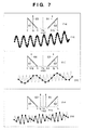
- Figs. 7(1-a) to 7(3-b) schematically show the states of artifacts to explain artifacts belonging to categories (A) and (B).
- A the first- and higher-order harmonics of a grid stripe pattern are not resolved.
- Fig. 7(1-a) shows the state of an artifact belonging to category (A) in the frequency domain (only the positive region).
- Reference numeral 61 denotes an image component region, which exhibits a substantially maximum frequency fi; and 62, an image harmonic component mathematically produced by sampling.
- a line spectrum 63 is a grid stripe pattern component having a frequency fg. As shown in Fig. 7(1-a), since this component overlaps the image component 61 to impair the image quality, and has a low frequency, the observer experiences a sense of incongruity from the stripe pattern.
- Fig. 7(1-b) one-dimensionally shows how sampling is performed.
- " ⁇ " bullet indicates a sampling point.
- Fig. 7(2-a) shows the state of another artifact belonging to category (A) in the frequency domain (only in the positive region).
- a region 61 is an image component region and exhibits the maximum frequency fi. Since the frequency fg of the grid is higher than the Nyquist frequency fnq that is 1/2 the sampling frequency fs, a frequency component 64 of fs - fg, which is aliasing, appears.
- the frequency component 64 as aliasing overlaps the image component 61 and impairs the image quality, and hence a stripe pattern gives the observer a sense of incongruity.
- Fig. 7(2-b) one-dimensionally shows how sampling is performed. In Fig.
- the frequency fg of the grid stripe pattern must satisfy the following inequality, in relation to the maximum frequency fi of the image and the sampling frequency fs: fi ⁇ fg ⁇ fs - fi (fi ⁇ fs/2)
- an artifact belonging to category (B) may be produced.
- Fig. 7(3-a) shows a state of an artifact when the grid stripe pattern frequency is set in the spatial frequency region which satisfies inequality (3).
- Fig. 7(3-b) one-dimensionally shows how sampling is performed.
- " ⁇ " (bullet) indicates a sampling point, and the dashed line indicates a signal form before sampling.
- beat noise is produced.
- a sine wave having the spatial frequency fg is sampled at the sampling frequency fs.
- fg > fs/2 is set in consideration of the grid actually used. This is not a necessary condition.
- a line spectrum pair corresponding to the frequency of the sine wave is produced. Let a/2 be the peak of each line spectrum, and a x cos (2 ⁇ fgx) be the initial grid image.
- a cosine wave having the frequency fg is sampled at the frequency fs, two cosine waves appear below fs.
- Equation (5) represents beat noise, which is equivalent to the amplitude modulated by a sine wave having a frequency corresponding to the difference between the two sine waves.
- (fg/2 - fs) becomes a small value other than 0, an unstable amplitude variation (beat) with a low frequency occurs.
- a sampled signal is reconstructed by connecting the sampling points with a straight line or the like. This means differs from an ideal filtering means according to the sampling theorem.
- a person with normal visual perception or display apparatus interpolates by connecting neighboring points with a straight line without using any ideal filter (convolution using a sinc function as a kernel) as in the sampling theorem.
- s(f) sin 2 ( ⁇ f/fs)/( ⁇ f/fs) 2
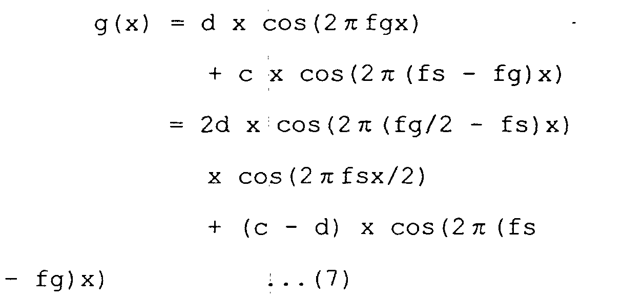
- c/2 and d/2 be the heights of a line spectrum pair at mirror-image positions after filtering.
- the first term of equation (7) represents beat component; and the second term, a general sine wave component.
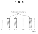
- the frequency of the grid stripe pattern is set to be equal to or less than 80% (equal to or less than 40% of the sampling frequency) of the Nyquist frequency. In practice, however, this frequency has its own lower limit. Since an artifact originating from the stripe pattern itself, i.e., stripe pattern information, is not allowed to overlap an image component, the maximum frequency of the image component needs to be lower than the lower limit frequency of the grid stripe pattern.
- the sampling pitch is often set such that a spatial frequency required generally is equal to or less than 60% of the Nyquist frequency (equal to or less than 30% of the sampling frequency). That is, the sampling pitch is set such that grid stripe pattern information appears at a frequency equal to or higher than the sampling frequency.
- the Nyquist frequency is 5 cyc/mm.
- the frequency of an image component which is generally used is equal to or less than 30% of the sampling frequency, i.e., 3 cyc/mm. That is, the lower limit frequency of stripe pattern information is 3 cyc/mm, and the upper limit frequency is 40% of the sampling frequency, i.e., 4 cyc/mm. If, therefore, the frequency of a grid stripe pattern is set within the range of 3 to 4 cyc/mm, no conspicuous beat appears in a grid stripe pattern and interferes with observation.
- the frequency range of the grid body is given by fs(n + 0.3) ⁇ fs(n + 0.4) or fs(n + 0.6) ⁇ fs(n + 0.8) [cyc/mm]
- the frequency of the grid body (the number of grid elements) is determined within the above range in consideration of scattered ray removing performance as the primary object of the grid, the resolution of a flat panel sensor, and the like.
- a grid stripe pattern frequency of 6 to 7 cyc/mm can be selected, at which the second harmonic is difficult to resolve and the scattered ray removing ratio is high.
- the frequency of the grid to be used is selected by the above calculation such that the observer can be satisfied to some degree without removing any grid stripe pattern information owing to some experience or depending on an application purpose, thus overcoming the problem.
- the grid stripe pattern information can be removed to some extent by filtering.
- removing the grid stripe pattern information by setting a grid stripe pattern frequency in the above manner even if the pattern information cannot be completely removed, reducing the intensity of the grid stripe pattern will minimize the influence on the observer.
- Fig. 1 is a schematic view of the first embodiment.
- Fig. 1 shows a system for imaging the human body lying on a table.
- Reference numeral 1 denotes an X-ray tube; 2, a human body as an object to be imaged; 11, a grid for removing scattered X-rays, which is a detachable grid for removing scattered X-rays from the object 2; 3, an X-ray sensor panel for converting an X-ray intensity distribution (X-ray transmission distribution) into a charge distribution, two-dimensionally sampling the distribution at desired intervals, and sequentially outputting the sampled data; 5, an analog/digital converter; 4, a controller for controlling the X-ray radiation timing and image acquisition timing; and 6, a memory for temporarily storing an image.
- the X-ray sensor panel 3 varies in offset and gain for each pixel.
- an offset value as an image acquired without any radiation of X-rays is stored in a memory 8, whereas data obtained by logarithmically converting a gain value acquired without the object 2 and grid 11 is stored in a memory 9.
- Reference numeral 7 denotes a conversion unit for logarithmic conversion, and more specifically, a lookup table.
- An acquired image of the human body is logarithmically converted after the offset value in the memory 8 is subtracted (removed) from the image.
- the difference between the resultant value and the gain value in the memory 9 is calculated (division) to obtain an X-ray intensity distribution image having undergone correction of a variation in gain value.
- This image is temporarily stored in a memory 10. Thereafter, the stored image is extracted and subjected to image storage, image processing, image display, and hardcopy operation, and the like to be used for diagnosis and the like.
- a block 12 is an image processing means (filtering means) for removing grid stripe pattern information by image processing (filtering).
- the image processing means 12 removes a grid stripe pattern component by spatial filtering using the image stored in the memory 10.
- a mechanism 13 is a selection means (switch) that is operated by the operator to choose between using the filtering means 12 or not using it in accordance with an output from an external output from a grid removing operation effective setting means (mechanism) 16 or operation panel 20. The flow of a signal can be changed to skip the operation of the block 12 in accordance with the selection made through the selection means 13.
- the X-ray sensor panel 3 has a plurality of pixels distributed vertically and horizontally at a pitch of-0.1 mm in a two-dimensional space.
- two-dimensional, discrete sampling is performed.
- the grid stripe pattern frequency (the number of grid elements) of the grid 11 is set to 6 to 7 cyc/mm, and hence the observer can observe an image without a sense of incongruity even if the grid tripe pattern information is not removed by filtering.
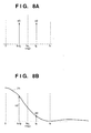
- Fig. 2A schematically shows the state of a one-dimensional amplitude spectrum in a direction perpendicular to the grid stripe pattern of the image stored in the memory 10.
- reference numeral 32 denotes a spectrum of an image component; and 31, a spectrum of a grid stripe pattern component, which exhibits a substantial spectrum form with noise being neglected. Even if the grid stripe pattern component 31 exists, the observer observes only this stable frequency component, and there is no component associated with beat noise. Therefore, as the observer becomes accustomed to the stripe pattern or recognizes it, the existence of the stripe pattern does not relatively interfere with the observation.
- Fig. 2B schematically shows the state of a spectrum upon execution of grid removing filtering.
- Reference numeral 33 denotes an example of a filter characteristic; and 34, an image spectrum after filtering.
- the filter cannot have a steep characteristic. If, therefore, the grid stripe pattern component 31 is removed, part of an image component inevitably deteriorates in response characteristic. In consideration of this, the operator chooses between removal and nonremoval of the grid. In this embodiment, when the acquired image exhibits the gain value stored in the memory 9, no problem arises if the image is acquired without removing the grid 11 because the frequency of the grid is constant.
- Fig. 3 is a flow chart for the implementation of this embodiment by means of software.
- a process block (step) is divided into operations in blocks Cl to C11.
- the operation in block C1 is executed to acquire an image of a gain value.
- An image A is obtained by radiating X-rays without any object.
- this image is logarithmically converted into an image B.
- an offset value is obtained; an image C is obtained without radiating any X-rays.
- an image of the object is actually acquired; the grid is installed, and an image D is obtained by irradiating the object with X-rays.
- the image C is subtracted from the image D to obtain an image E having undergone offset correction.
- the image E is logarithmically converted into an image F.
- the image B is subtracted from the image F to obtain an object image G having undergone gain correction.
- filtering i.e., grid removing operation, is performed for the image G to obtain an object image H from which grid stripe pattern information is removed.
- the object image H is output. If no grid removing instruction is received, the object image G is output without any processing in block C11.
- a nonvolatile storage medium such as a magnetic disk may be used to always store image data including grid stripe pattern information to allow the operator to select an image without any grid stripe pattern information or an image with grid stripe pattern information or output them at once.
- this embodiment can be practiced with an arrangement including only an image storage system without any image acquisition system.
- Fig. 4 is a block diagram showing the second embodiment, in which the frequency of a grid stripe pattern, the sampling pitch of an X-ray sensor panel, and the like are set in the same manner as in Fig. 1.
- an application purpose table 14 is prepared. After an image is acquired, the operator selects an application purpose through an application purpose setting means 17 with respect to the image stored in a memory 10 or magnetic disk. As a consequence, whether to remove the grid or not is automatically selected. If a switch 13 selects the A side, the image in the memory 10 is filtered by a filtering unit 12 and output. If the switch 13 selects the B side, the image in the memory 10 is output without being filtered.
- the grid stripe pattern frequency (the number of grid elements) of a grid 11 is set to 6 to 7 cyc/mm, and hence the observer can observe an image without a sense of incongruity even if the grid tripe pattern information is not removed by filtering.
- the switch 13 is set on the A side.
- the switch 13 In displaying an image or performing hardcopy operation on a larger scale, i.e., 100% or more, the switch 13 is set on the B side to inhibit removal of a grid image so as to minimize an image blur. In displaying an image or performing hardcopy operation upon reduction, the switch 13 is set on the A side to remove a grid image. If an image is to be stored in another storage means, since removal processing can be performed for the stored image, the switch 13 is set on the B side to inhibit removal of a grid image, thus increasing the information amount.
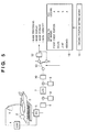
- Fig. 5 is a block diagram showing the third embodiment, in which the frequency of a grid stripe pattern, the sampling pitch of an X-ray sensor panel, and the like are set in the same manner as in Fig. 1.
- an imaging position table 18 is prepared. When the operator selects an application purpose through an imaging position setting means 19 with respect to the image stored in a memory 10 or magnetic dick upon imaging operation, whether to perform grid removing operation or not is automatically selected.
- the grid stripe pattern frequency (the number of grid elements) of a grid 11 is set to 6 to 7 cyc/mm, and hence the observer can observe an image without a sense of incongruity even if the grid tripe pattern information is not removed by filtering.
- a switch 13 is set on the B side to allow the observer to observe the image without any blur without removing a grid image.
- the switch 13 is set on the A side to allow the observer to observe the image without any grid image.
- the grid frequency is so set that a grid image does not relatively interfere with observation, if the contrast of the grid image is strong, it still interferes with the observer.
- the contrast of a grid image varies depending on the conditions (e.g., energy) of X-rays to be used. In some case, an object is imaged without any grid.
- the-spectrum of a given portion of an acquired image in a direction perpendicular to the grid is calculated, and whether to perform grid removing operation or not is selected depending on the peak value of the grid component (directly corresponding to the contrast value if it is a logarithmic image).
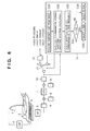
- Fig. 6 is a block diagram showing the fourth embodiment, in which the frequency of a grid stripe pattern, the sampling pitch of an X-ray sensor panel, and the like are set in the same manner as in Fig. 1.
- the grid stripe pattern frequency (the number of grid elements) of a grid 11 is set to 6 to 7 cyc/mm, and hence the observer can observe an image without a sense of incongruity even if the grid tripe pattern information is not removed by filtering.
- a block 15 in Fig. 6 includes software; a flow chart is shown in the block.
- block C21 in the flow chart an arbitrary line is acquired from an image from a memory 10.
- block C22 one-dimensional Fourier transformation is performed for this image to calculate an amplitude spectrum.
- an amplitude value (spectrum value) Vp corresponding to the grid frequency is measured from the amplitude spectrum value.
- the amplitude value Vp is compared with a threshold TH set in advance. If Vp is larger than TH, the corresponding grid image must be removed. To remove the grid image, therefore, a switch 13 is set on the A side in block C25. If Vp is not larger than TH, the switch 13 is set on the B side in block C26.
- the switch 13 may be selectively operated in accordance with the magnitude of contrast of a grid stripe pattern existing at the grid frequency. If the contrast is higher than a predetermined threshold, the switch 13 is set on the A side to remove a grid image. If the contrast is lower than the predetermined threshold, the switch 13 is set on the B side to inhibit the removal of a grid image.
- an image that can be observed by the observer with little sense of incongruity without removing a grid stripe pattern from the image can be formed by setting the frequency of the grid lead members to be equal to or lower than 40% of the sampling frequency at which the spatial frequency of a stripe image originating from the grid for removing scattered rays from the image and equal to or higher than the frequency (60% of the Nyquist frequency in general) at which a grid image does not easily interfere with observation of the image by the observer and does not overlap an image component.
- the filtering means 12 can choose between removal or nonremoval of a grid stripe pattern in accordance with selection through the switch 13. Since a grid stripe pattern is automatically removed in accordance with operation by the operator (observer), the application purpose of an image, imaging position, and the amplitude (intensity) of a grid stripe pattern, an appropriate image can be obtained by removing a grid stripe pattern only when required.
- an image that can be observed by the observer with little sense of incongruity without removing a grid stripe pattern from the image can be formed by setting the spatial frequency of a stripe pattern originating from the grid for removing scattered rays from the image to a predetermined value.
- an appropriate image can be obtained by removing a stripe pattern originating from the scattered ray removing grid.
- An image acquisition apparatus of the invention radiates X-rays by using a scattered ray removing grid (11) and two-dimensionally samples an X-ray transmission distribution on an object (2) to be imaged at desired sampling intervals.
- This apparatus includes an image acquisition means for acquiring an image by setting the intervals of elements of the scattered ray removing grid, without moving the scattered ray removing grid, such that the spatial frequency of a stripe pattern, in the image, which originates from the scattered ray removing grid becomes 40% or more of a sampling frequency that is the reciprocal of the sampling intervals.
Landscapes
- Health & Medical Sciences (AREA)
- Life Sciences & Earth Sciences (AREA)
- Engineering & Computer Science (AREA)
- Physics & Mathematics (AREA)
- High Energy & Nuclear Physics (AREA)
- Molecular Biology (AREA)
- Medical Informatics (AREA)
- Optics & Photonics (AREA)
- Heart & Thoracic Surgery (AREA)
- Biophysics (AREA)
- Spectroscopy & Molecular Physics (AREA)
- Nuclear Medicine, Radiotherapy & Molecular Imaging (AREA)
- General Physics & Mathematics (AREA)
- Pathology (AREA)
- Radiology & Medical Imaging (AREA)
- Biomedical Technology (AREA)
- Computer Vision & Pattern Recognition (AREA)
- Surgery (AREA)
- Animal Behavior & Ethology (AREA)
- General Health & Medical Sciences (AREA)
- Public Health (AREA)
- Veterinary Medicine (AREA)
- Apparatus For Radiation Diagnosis (AREA)
- Analysing Materials By The Use Of Radiation (AREA)
- Image Processing (AREA)
Abstract
Description
- Storage and transfer can be efficiently performed.
- Optimal images can be easily formed by digital image processing (a recovery from a failure in imaging operation can be made).
- Efficient diagnosis can be carried out.
- A reduction in the cost of diagnosis can be attained.
To reduce the influences of scattered X-rays and obtain a high-contrast image, an optimal means is to use a scattered ray removing grid having many lead plates arranged in the same direction as in a conventional scheme using silver-halide films.


(c - d)2/2d2 > 1 (condition under which the power of the second terminal exceeds that of the first term)

- A frequency that meets the approval of the observer when an acquired image is reproduced by a display apparatus or recording apparatus.
- When a maximum frequency is assumed, the sampling pitch is determined by regarding 1.5 to 2 times the assumed frequency as a maximum frequency (see Nakamizo et al., " Counting/Measurement" (Baihukan)).
Claims (54)
- An image acquisition apparatus characterized by comprising:a sensor for two-dimensionally sampling a radiation transmission distribution on an object to be imaged at desired sampling intervals; anda scattered ray removing grid for removing scattered rays, which is used without being moved during acquisition of an image by said sensor,wherein intervals of elements of said scattered ray removing grid are set such that a spatial frequency of a stripe pattern, in the image, which originates from said scattered ray removing grid becomes not less than 40% of a sampling frequency that is the reciprocal of the sampling intervals.
- The apparatus according to claim 1, characterized in that the spatial frequency of the stripe pattern originating from the scattered ray removing grid is not less than 30% of the sampling frequency.
- An image acquisition apparatus characterized by comprising:a sensor for two-dimensionally sampling a radiation transmission distribution on an object to be imaged at desired sampling intervals; anda scattered ray removing grid for removing scattered rays, which is used without being moved during acquisition of an image by said sensor,wherein intervals of elements of said scattered ray removing grid are set such that a spatial frequency of a stripe pattern, in the image, which originates from said scattered ray removing grid becomes not less than 30% of a sampling frequency that is the reciprocal of the sampling intervals.
- An image acquisition apparatus characterized by comprising:a sensor for two-dimensionally sampling a radiation transmission distribution on an object to be imaged at desired sampling intervals; anda scattered ray removing grid for removing scattered rays, which is used without being moved during acquisition of an image by said sensor,wherein intervals of elements of said scattered ray removing grid are set such that a spatial frequency of a stripe pattern, in the image, which originates from the scattered ray removing grid becomes fs(n + 0.3) ∼ fs(n + 0.4) or fs (n + 0.6) ∼ fs (n + 0.8) [cyc/mm] where 1/fs [mm] is the desired intervals (fs is an arbitrary positive number) and n is an integer not less than 0.
- The apparatus according to claim 4, characterized in that the intervals of the elements of the scattered ray removing grid are set such that the spatial frequency of the stripe pattern becomes 6 to 7 [cyc/mm].
- The apparatus according to claim 4, characterized in that the intervals of the elements of the scattered ray removing grid are set such that the spatial frequency of the stripe pattern becomes 3 to 4 [cyc/mm].
- The apparatus according to claim 1, characterized by further comprising offset value removing means for removing an offset value from the image acquired by radiating the radiation.
- The apparatus according to claim 7, characterized in that said offset value removing means includes first subtraction means, as a method of practicing claim 7, for subtracting an image acquired without radiating radiation from the image acquired by radiating the radiation.
- The apparatus according to claim 1, characterized by further comprising gain value correction means for correcting a variation in gain value with respect to the acquired image.
- The apparatus according to claim 9, characterized in that said gain value correction means includes division means for dividing the acquired image by an image acquired without the object.
- The apparatus according to claim 9, characterized in that said gain value correction means includes second subtraction means for subtracting an image obtained by logarithmically converting an image acquired without the object from an image obtained by logarithmically converting the acquired image.
- The apparatus according to claim 1, characterized by further comprising filtering means for removing a stripe pattern, in the image, which originates from the scattered ray removing grid by filtering the acquired image.
- The apparatus according to claim 12, characterized in that said filtering means performs filtering in accordance with operation performed by an operator.
- The apparatus according to claim 12, characterized in that said filtering means performs filtering in accordance with an application purpose of an image.
- The apparatus according to claim 14, characterized in that said filtering means performs filtering if the purpose is to perform spatial frequency emphasis processing for an image.
- The apparatus according to claim 14, characterized in that said filtering means performs no filtering if the purpose is to display an image or perform hardcopy operation on a scale not less than 100% or hardcopy operation.
- The apparatus according to claim 14, characterized in that said filtering means performs filtering if the purpose is to display an image or perform hardcopy operation upon reduction of the image.
- The apparatus according to claim 14, characterized in that said filtering means performs no filtering if the purpose is to store an image.
- The apparatus according to claim 12, characterized in that said filtering means performs filtering in accordance with an imaging position.
- The apparatus according to claim 19, characterized in that said filtering means performs no filtering if the imaging position is a bone portion.
- The apparatus according to claim 19, characterized in that said filtering means performs no filtering if the imaging position is a pelvis or joint.
- The apparatus according to claim 19, characterized in that said filtering means performs filtering if the imaging position is a chest portion or abdominal portion.
- The apparatus according to claim 12,
characterized in that said filtering means performs filtering in accordance with a magnitude of an amplitude of a frequency of a stripe pattern originating from the scattered ray removing grid. - The apparatus according to claim 12, characterized in that said filtering means performs filtering if the amplitude of the frequency of the stripe pattern originating from the scattered ray removing grid is larger than a predetermined threshold.
- An image acquisition method of radiating radiation by using a scattered ray removing grid without moving the scattered ray removing grid and two-dimensionally sampling a radiation transmission distribution on an object to be imaged at desired sampling intervals,
characterized by comprising
the step of acquiring an image by setting intervals of elements of the scattered ray removing grid such that a spatial frequency of a stripe pattern, in the image, which originates from the scattered ray removing grid becomes not less than 40% of a sampling frequency that is the reciprocal of the sampling intervals. - An image acquisition method of radiating radiation by using a scattered ray removing grid without moving the scattered ray removing grid and two-dimensionally sampling a radiation transmission distribution on an object to be imaged at desired sampling intervals,
characterized by comprising
the step of acquiring an image by setting intervals of elements of the scattered ray removing grid such that a spatial frequency of a stripe pattern, in the image, which originates from the scattered ray removing grid becomes not less than 30% of a sampling frequency that is the reciprocal of the sampling intervals. - An image acquisition method of radiating radiation by using a scattered ray removing grid without moving the scattered ray removing grid and two-dimensionally sampling a radiation transmission distribution on an object to be imaged at desired sampling intervals,
characterized by comprising
the step of acquiring an image by setting intervals of elements of the scattered ray removing grid such that a spatial frequency of a stripe pattern, in the image, which originates from the scattered ray removing grid becomes fs(n + 0.3) ∼ fs(n + 0.4) or fs(n + 0.6) ∼ fs(n + 0.8) [cyc/mm] where 1/fs [mm] is the desired intervals (fs is an arbitrary positive number) and n is an integer not less than 0. - An image acquisition apparatus characterized by comprising:image acquisition means for radiating radiation by using a scattered ray removing grid and acquiring an image by two-dimensionally sampling a radiation transmission distribution on an object to be imaged at desired intervals;image processing means for removing a stripe pattern originating from the scattered ray removing grid from the acquired image by image processing; andselection means for allowing selection between removal and nonremoval of the stripe pattern originating from the scattered ray removing grid by using said image processing means.
- The apparatus according to claim 28, characterized in that said image processing means removes the stripe pattern originating from the scattered ray removing grid by filtering.
- The apparatus according to-claim 28, characterized in that said selection means selects between removing the stripe pattern or not removing the stripe pattern in accordance with operation performed by an operator.
- The apparatus according to claim 28, characterized in that said selection means selects between removing the stripe pattern or not removing the stripe pattern in accordance with an application purpose of an image.
- The apparatus according to claim 31, characterized in that said selection means selects removing the stripe pattern if the purpose is to perform spatial frequency emphasis processing for an image.
- The apparatus according to claim 31, characterized in that said selection means selects not removing the stripe pattern if the purpose is to display an image or perform hardcopy operation on a scale not less than 100% or hardcopy operation.
- The apparatus according to claim 31, characterized in that said selection means selects removing the stripe pattern if the purpose is to display an image or perform hardcopy operation upon reduction of the image.
- The apparatus according to claim 31, characterized in that said selection means selects not removing the stripe pattern if the purpose is to store an image.
- The apparatus according to claim 28, characterized in that said selection means selects between removing the stripe pattern or not removing the stripe pattern in accordance with an imaging position.
- The apparatus according to claim 36, characterized in that said selection means selects not removing the stripe pattern if the imaging position is a bone portion.
- The apparatus according to claim 36, characterized in that said selection means selects not removing the stripe pattern if the imaging position is a pelvis or joint.
- The apparatus according to claim 36, characterized in that said selection means selects removing the stripe pattern if the imaging position is a chest portion or abdominal portion.
- The apparatus according to claim 28,
characterized in that said selection means selects between removing the stripe pattern and not removing the stripe pattern in accordance with a magnitude of an amplitude of a frequency of a stripe pattern originating from the scattered ray removing grid. - The apparatus according to claim 40, characterized in that said selection means selects removing the stripe pattern if the amplitude of the frequency of the stripe pattern originating from the scattered ray removing grid is larger than a predetermined threshold.
- The apparatus according to claim 28,
characterized in that said selection means selects between removal or nonremoval of the stripe pattern in accordance with a magnitude of contrast of the stripe pattern originating from the scattered ray removing grid. - The apparatus according to claim 28, characterized by further comprising offset value removing means for removing an offset value from the image acquired by radiating the radiation.
- The apparatus according to claim 43, characterized in that said offset value removing means includes first subtraction means for subtracting an image acquired without radiating radiation from the image acquired by radiating the radiation.
- The apparatus according to claim 28, characterized by further comprising gain value correction means for correcting a variation in gain value with respect to the acquired image.
- The apparatus according to claim 45, characterized in that said gain value correction means includes division means, as a method of implementing claim 45, which divides the acquired image by an image acquired without the object.
- The apparatus according to claim 45, characterized in that said gain value correction means includes second subtraction means for subtracting an image obtained by logarithmically converting an image acquired without the object from an image obtained by logarithmically converting the acquired image.
- An image acquisition method characterized by comprising:(a) the step of radiating radiation by using a scattered ray removing grid and acquiring an image by two-dimensionally sampling a radiation transmission distribution on an object to be imaged at desired intervals;(b) the step of selecting between removal and nonremoval of a stripe pattern originating from the scattered ray removing grid from the acquired image by image processing; and(c) the step of removing the stripe pattern originating from the scattered ray removing grid by image processing in accordance with the selection.
- The apparatus according to claim 28, characterized in thatthe scattered ray removing grid is used without being moved, andsaid image acquisition means acquires an image by setting intervals of elements of the scattered ray removing grid such that a spatial frequency of a stripe pattern, in the image, which originates from the scattered ray removing grid becomes not less than 40% of a sampling frequency that is the reciprocal of the sampling intervals.
- The apparatus, according to claim 28, characterized in thatthe scattered ray removing grid is used without being moved, andsaid image acquisition means acquires an image by setting intervals of elements of the scattered ray removing grid such that a spatial frequency of a stripe pattern, in the image, which originates from the scattered ray removing grid becomes not less than 30% of a sampling frequency that is the reciprocal of the sampling intervals.
- The apparatus according to claim 28, characterized in thatthe scattered ray removing grid is used without being moved, andsaid image acquisition means acquires an image by setting intervals of elements of the scattered ray removing grid such that a spatial frequency of a stripe pattern, in the image, which originates from the scattered ray removing grid becomes fs(n + 0.3) ∼ fs(n + 0.4) or fs(n + 0.6) ∼ fs (n + 0.8) [cyc/mm] where 1/fs [mm] is the desired intervals (fs is an arbitrary positive number) and n is an integer not less than 0.
- The method according to claim 48, characterized in thatthe scattered ray removing grid is used without being moved, andthe image acquisition step comprises acquiring an image by setting intervals of elements of the scattered ray removing grid such that a spatial frequency of a stripe pattern, in the image, which originates from the scattered ray removing grid becomes not less than 40% of a sampling frequency that is the reciprocal of the sampling intervals.
- The method according to claim 48, characterized in thatthe scattered ray removing grid is used without being moved, andthe image acquisition step comprises acquiring an image by setting intervals of elements of the scattered ray removing grid such that a spatial frequency of a stripe pattern, in the image, which originates from the scattered ray removing grid becomes not less than 30% of a sampling frequency that is the reciprocal of the sampling intervals.
- The method according to claim 48, characterized in thatthe scattered ray removing grid is used without being moved, andthe image acquisition step comprises acquiring an image by setting intervals of elements of the scattered ray removing grid such that a spatial frequency of a stripe pattern, in the image, which originates from the scattered ray removing grid becomes fs(n + 0.3) ∼ fs(n + 0.4) or fs(n + 0.6) ∼ fs (n + 0.8) [cyc/mm] where 1/fs [mm] is the desired intervals (fs is an arbitrary positive number) and n is an integer not less than 0.
Applications Claiming Priority (4)
| Application Number | Priority Date | Filing Date | Title |
|---|---|---|---|
| JP2000028161 | 2000-02-04 | ||
| JP2000028207 | 2000-02-04 | ||
| JP2000028207A JP4612754B2 (en) | 2000-02-04 | 2000-02-04 | Image acquisition apparatus and image acquisition method |
| JP2000028161A JP4500400B2 (en) | 2000-02-04 | 2000-02-04 | Image acquisition apparatus and image acquisition method |
Publications (3)
| Publication Number | Publication Date |
|---|---|
| EP1126289A2 true EP1126289A2 (en) | 2001-08-22 |
| EP1126289A3 EP1126289A3 (en) | 2006-01-25 |
| EP1126289B1 EP1126289B1 (en) | 2013-11-13 |
Family
ID=26584914
Family Applications (1)
| Application Number | Title | Priority Date | Filing Date |
|---|---|---|---|
| EP20010102319 Expired - Lifetime EP1126289B1 (en) | 2000-02-04 | 2001-02-01 | Image acquisition method and apparatus |
Country Status (2)
| Country | Link |
|---|---|
| US (1) | US20010033638A1 (en) |
| EP (1) | EP1126289B1 (en) |
Cited By (5)
| Publication number | Priority date | Publication date | Assignee | Title |
|---|---|---|---|---|
| EP1202555A3 (en) * | 2000-08-28 | 2004-12-29 | Fuji Photo Film Co., Ltd. | Image signal generating method, apparatus and program |
| US6912266B2 (en) | 2002-04-22 | 2005-06-28 | Siemens Aktiengesellschaft | X-ray diagnostic facility having a digital X-ray detector and a stray radiation grid |
| FR2939019A1 (en) * | 2008-11-28 | 2010-06-04 | Gen Electric | Medical imaging method for acquiring e.g. mammogram image, involves receiving radiation, and implementing low-pass filtering on images near Nyquist frequency at acquisition or subsequent occasion |
| EP2196148A4 (en) * | 2007-10-02 | 2013-06-26 | Shimadzu Corp | Radiation image processor and radiation image processing program |
| US9968316B2 (en) | 2010-12-29 | 2018-05-15 | General Electric Company | High-frequency anti-scatter grid movement profile for line cancellation |
Families Citing this family (10)
| Publication number | Priority date | Publication date | Assignee | Title |
|---|---|---|---|---|
| JP2003008885A (en) | 2001-06-19 | 2003-01-10 | Fuji Photo Film Co Ltd | Image reproduction system |
| JP3624173B2 (en) * | 2001-07-26 | 2005-03-02 | キヤノン株式会社 | Radiation imaging equipment |
| JP2004053584A (en) * | 2002-05-30 | 2004-02-19 | Canon Inc | Image correction apparatus and method |
| JP4596748B2 (en) * | 2003-05-07 | 2010-12-15 | キヤノン株式会社 | Radiographic imaging apparatus and reconstruction method in radiographic imaging apparatus |
| JP4497837B2 (en) * | 2003-05-12 | 2010-07-07 | キヤノン株式会社 | Radiation imaging equipment |
| US7729559B2 (en) * | 2006-05-22 | 2010-06-01 | Ge Healthcare Bio-Sciences Corp. | System and method for optical section image line removal |
| JP5375655B2 (en) * | 2010-02-18 | 2013-12-25 | 株式会社島津製作所 | Radiography equipment |
| JP6071853B2 (en) * | 2013-11-26 | 2017-02-01 | 富士フイルム株式会社 | Radiation image processing apparatus, method and program |
| CN107203983B (en) | 2016-03-17 | 2024-03-22 | 通用电气公司 | Method and system for reducing grid line artifacts in X-ray images |
| JP2024025163A (en) * | 2022-08-10 | 2024-02-26 | キヤノン株式会社 | Radiography apparatus and its control method, radiography system, program |
Citations (3)
| Publication number | Priority date | Publication date | Assignee | Title |
|---|---|---|---|---|
| US4317179A (en) | 1978-12-26 | 1982-02-23 | Fuji Photo Film Co., Ltd. | Method and apparatus for processing a radiographic image |
| JPH09283606A (en) | 1996-04-08 | 1997-10-31 | Sumitomo Osaka Cement Co Ltd | Electrostatic chuck |
| US6201249B1 (en) | 1997-10-16 | 2001-03-13 | Canon Kabushiki Kaisha | X-ray imaging system |
Family Cites Families (3)
| Publication number | Priority date | Publication date | Assignee | Title |
|---|---|---|---|---|
| EP0792061B1 (en) * | 1989-04-11 | 2003-01-29 | Fuji Photo Film Co., Ltd. | Method for generating radiation image signals and radiation read-out apparatus |
| JP3776485B2 (en) * | 1995-09-18 | 2006-05-17 | 東芝医用システムエンジニアリング株式会社 | X-ray diagnostic equipment |
| US6333990B1 (en) * | 1998-06-02 | 2001-12-25 | General Electric Company | Fourier spectrum method to remove grid line artifacts without changing the diagnostic quality in X-ray images |
-
2001
- 2001-01-31 US US09/773,095 patent/US20010033638A1/en not_active Abandoned
- 2001-02-01 EP EP20010102319 patent/EP1126289B1/en not_active Expired - Lifetime
Patent Citations (3)
| Publication number | Priority date | Publication date | Assignee | Title |
|---|---|---|---|---|
| US4317179A (en) | 1978-12-26 | 1982-02-23 | Fuji Photo Film Co., Ltd. | Method and apparatus for processing a radiographic image |
| JPH09283606A (en) | 1996-04-08 | 1997-10-31 | Sumitomo Osaka Cement Co Ltd | Electrostatic chuck |
| US6201249B1 (en) | 1997-10-16 | 2001-03-13 | Canon Kabushiki Kaisha | X-ray imaging system |
Cited By (5)
| Publication number | Priority date | Publication date | Assignee | Title |
|---|---|---|---|---|
| EP1202555A3 (en) * | 2000-08-28 | 2004-12-29 | Fuji Photo Film Co., Ltd. | Image signal generating method, apparatus and program |
| US6912266B2 (en) | 2002-04-22 | 2005-06-28 | Siemens Aktiengesellschaft | X-ray diagnostic facility having a digital X-ray detector and a stray radiation grid |
| EP2196148A4 (en) * | 2007-10-02 | 2013-06-26 | Shimadzu Corp | Radiation image processor and radiation image processing program |
| FR2939019A1 (en) * | 2008-11-28 | 2010-06-04 | Gen Electric | Medical imaging method for acquiring e.g. mammogram image, involves receiving radiation, and implementing low-pass filtering on images near Nyquist frequency at acquisition or subsequent occasion |
| US9968316B2 (en) | 2010-12-29 | 2018-05-15 | General Electric Company | High-frequency anti-scatter grid movement profile for line cancellation |
Also Published As
| Publication number | Publication date |
|---|---|
| US20010033638A1 (en) | 2001-10-25 |
| EP1126289B1 (en) | 2013-11-13 |
| EP1126289A3 (en) | 2006-01-25 |
Similar Documents
| Publication | Publication Date | Title |
|---|---|---|
| US6826256B2 (en) | Apparatus and method for a radiation image through a grid | |
| EP1126289A2 (en) | Image acquisition method and apparatus | |
| JP3193806B2 (en) | Noise reduction method and apparatus | |
| Seibert et al. | Removal of image intensifier veiling glare by mathematical deconvolution techniques | |
| US5644662A (en) | Multiple processing of radiographic images based on a pyramidal image decomposition | |
| US5960058A (en) | Method for generating X-ray image and apparatus therefor | |
| EP0777891B1 (en) | Image processing for noise reduction | |
| JP3467285B2 (en) | Radiation image processing method | |
| US5878108A (en) | Method for generating X-ray image and apparatus therefor | |
| JP3903027B2 (en) | Radiation image processing method and apparatus, and grid selection method and apparatus | |
| EP0117155A2 (en) | Multiple measurement noise reducing system using space-variant filters | |
| JPH08329242A (en) | Method for enhancement of image quality | |
| US5825846A (en) | Noise reduction in an image | |
| EP2640054B1 (en) | Image processing apparatus and control method | |
| EP1766570B1 (en) | System and method for the correction of temporal artifacts in tomographic images | |
| US6704437B1 (en) | Noise estimation method and apparatus for noise adaptive ultrasonic image processing | |
| JP2003037777A (en) | Radiation image processing apparatus, image processing system, radiation image processing method, storage medium, and program | |
| JP4500400B2 (en) | Image acquisition apparatus and image acquisition method | |
| JP4612754B2 (en) | Image acquisition apparatus and image acquisition method | |
| EP0589467B1 (en) | Nuclear medicine imaging apparatus | |
| JP3445258B2 (en) | Radiation image processing apparatus, image processing system, radiation image processing method, storage medium, program, radiation imaging apparatus, and radiation imaging system | |
| Busse et al. | Methodology to measure fundamental performance parameters of X-ray detectors | |
| JP2024013417A (en) | Image processing device, image processing method, and program | |
| JP3465028B2 (en) | How to read radiation image information | |
| JP2001292324A (en) | Image processing apparatus and image processing method |
Legal Events
| Date | Code | Title | Description |
|---|---|---|---|
| PUAI | Public reference made under article 153(3) epc to a published international application that has entered the european phase |
Free format text: ORIGINAL CODE: 0009012 |
|
| AK | Designated contracting states |
Kind code of ref document: A2 Designated state(s): AT BE CH CY DE DK ES FI FR GB GR IE IT LI LU MC NL PT SE TR |
|
| AX | Request for extension of the european patent |
Free format text: AL;LT;LV;MK;RO;SI |
|
| PUAL | Search report despatched |
Free format text: ORIGINAL CODE: 0009013 |
|
| AK | Designated contracting states |
Kind code of ref document: A3 Designated state(s): AT BE CH CY DE DK ES FI FR GB GR IE IT LI LU MC NL PT SE TR |
|
| AX | Request for extension of the european patent |
Extension state: AL LT LV MK RO SI |
|
| 17P | Request for examination filed |
Effective date: 20060725 |
|
| AKX | Designation fees paid |
Designated state(s): DE FR GB NL |
|
| 17Q | First examination report despatched |
Effective date: 20080613 |
|
| GRAP | Despatch of communication of intention to grant a patent |
Free format text: ORIGINAL CODE: EPIDOSNIGR1 |
|
| GRAP | Despatch of communication of intention to grant a patent |
Free format text: ORIGINAL CODE: EPIDOSNIGR1 |
|
| INTG | Intention to grant announced |
Effective date: 20130612 |
|
| GRAS | Grant fee paid |
Free format text: ORIGINAL CODE: EPIDOSNIGR3 |
|
| GRAA | (expected) grant |
Free format text: ORIGINAL CODE: 0009210 |
|
| AK | Designated contracting states |
Kind code of ref document: B1 Designated state(s): DE FR GB NL |
|
| REG | Reference to a national code |
Ref country code: GB Ref legal event code: FG4D |
|
| REG | Reference to a national code |
Ref country code: DE Ref legal event code: R096 Ref document number: 60148437 Country of ref document: DE Effective date: 20140109 |
|
| REG | Reference to a national code |
Ref country code: NL Ref legal event code: T3 |
|
| REG | Reference to a national code |
Ref country code: DE Ref legal event code: R097 Ref document number: 60148437 Country of ref document: DE |
|
| PLBE | No opposition filed within time limit |
Free format text: ORIGINAL CODE: 0009261 |
|
| STAA | Information on the status of an ep patent application or granted ep patent |
Free format text: STATUS: NO OPPOSITION FILED WITHIN TIME LIMIT |
|
| 26N | No opposition filed |
Effective date: 20140814 |
|
| REG | Reference to a national code |
Ref country code: DE Ref legal event code: R097 Ref document number: 60148437 Country of ref document: DE Effective date: 20140814 |
|
| REG | Reference to a national code |
Ref country code: FR Ref legal event code: PLFP Year of fee payment: 16 |
|
| PGFP | Annual fee paid to national office [announced via postgrant information from national office to epo] |
Ref country code: NL Payment date: 20160107 Year of fee payment: 16 |
|
| PGFP | Annual fee paid to national office [announced via postgrant information from national office to epo] |
Ref country code: GB Payment date: 20160224 Year of fee payment: 16 Ref country code: FR Payment date: 20160225 Year of fee payment: 16 |
|
| REG | Reference to a national code |
Ref country code: NL Ref legal event code: MM Effective date: 20170301 |
|
| GBPC | Gb: european patent ceased through non-payment of renewal fee |
Effective date: 20170201 |
|
| PG25 | Lapsed in a contracting state [announced via postgrant information from national office to epo] |
Ref country code: NL Free format text: LAPSE BECAUSE OF NON-PAYMENT OF DUE FEES Effective date: 20170301 |
|
| REG | Reference to a national code |
Ref country code: FR Ref legal event code: ST Effective date: 20171031 |
|
| PG25 | Lapsed in a contracting state [announced via postgrant information from national office to epo] |
Ref country code: FR Free format text: LAPSE BECAUSE OF NON-PAYMENT OF DUE FEES Effective date: 20170228 |
|
| PG25 | Lapsed in a contracting state [announced via postgrant information from national office to epo] |
Ref country code: GB Free format text: LAPSE BECAUSE OF NON-PAYMENT OF DUE FEES Effective date: 20170201 |
|
| PGFP | Annual fee paid to national office [announced via postgrant information from national office to epo] |
Ref country code: DE Payment date: 20180430 Year of fee payment: 18 |
|
| REG | Reference to a national code |
Ref country code: DE Ref legal event code: R119 Ref document number: 60148437 Country of ref document: DE |
|
| PG25 | Lapsed in a contracting state [announced via postgrant information from national office to epo] |
Ref country code: DE Free format text: LAPSE BECAUSE OF NON-PAYMENT OF DUE FEES Effective date: 20190903 |