EP1125820A2 - Steering device for car - Google Patents
Steering device for car Download PDFInfo
- Publication number
- EP1125820A2 EP1125820A2 EP01301278A EP01301278A EP1125820A2 EP 1125820 A2 EP1125820 A2 EP 1125820A2 EP 01301278 A EP01301278 A EP 01301278A EP 01301278 A EP01301278 A EP 01301278A EP 1125820 A2 EP1125820 A2 EP 1125820A2
- Authority
- EP
- European Patent Office
- Prior art keywords
- column
- inner column
- car
- clamp members
- outer column
- Prior art date
- Legal status (The legal status is an assumption and is not a legal conclusion. Google has not performed a legal analysis and makes no representation as to the accuracy of the status listed.)
- Granted
Links
- 238000005266 casting Methods 0.000 claims description 13
- 230000004048 modification Effects 0.000 description 8
- 238000012986 modification Methods 0.000 description 8
- 230000002093 peripheral effect Effects 0.000 description 8
- 230000003014 reinforcing effect Effects 0.000 description 6
- 238000005452 bending Methods 0.000 description 5
- 238000000034 method Methods 0.000 description 5
- 230000003449 preventive effect Effects 0.000 description 3
- 230000008569 process Effects 0.000 description 3
- HCHKCACWOHOZIP-UHFFFAOYSA-N Zinc Chemical compound [Zn] HCHKCACWOHOZIP-UHFFFAOYSA-N 0.000 description 2
- XAGFODPZIPBFFR-UHFFFAOYSA-N aluminium Chemical compound [Al] XAGFODPZIPBFFR-UHFFFAOYSA-N 0.000 description 2
- 229910052782 aluminium Inorganic materials 0.000 description 2
- 239000002775 capsule Substances 0.000 description 2
- 238000010276 construction Methods 0.000 description 2
- 238000004519 manufacturing process Methods 0.000 description 2
- 230000007246 mechanism Effects 0.000 description 2
- 230000003252 repetitive effect Effects 0.000 description 2
- 239000011701 zinc Substances 0.000 description 2
- 229910052725 zinc Inorganic materials 0.000 description 2
- 230000008901 benefit Effects 0.000 description 1
- 230000010485 coping Effects 0.000 description 1
- 230000002708 enhancing effect Effects 0.000 description 1
- 239000000463 material Substances 0.000 description 1
- 230000010355 oscillation Effects 0.000 description 1
- 230000000149 penetrating effect Effects 0.000 description 1
- 125000006850 spacer group Chemical group 0.000 description 1
Images








Classifications
-
- B—PERFORMING OPERATIONS; TRANSPORTING
- B62—LAND VEHICLES FOR TRAVELLING OTHERWISE THAN ON RAILS
- B62D—MOTOR VEHICLES; TRAILERS
- B62D1/00—Steering controls, i.e. means for initiating a change of direction of the vehicle
- B62D1/02—Steering controls, i.e. means for initiating a change of direction of the vehicle vehicle-mounted
- B62D1/16—Steering columns
- B62D1/18—Steering columns yieldable or adjustable, e.g. tiltable
- B62D1/184—Mechanisms for locking columns at selected positions
Definitions
- the present invention relates generally to a steering device for a car, and more particularly to a steering device for a car, which is capable of adjusting a tilt angle of a steering shaft and/or an axial position of the steering shaft.
- One of the steering devices for cars is a tilt telescopic type steering device capable of adjusting a tilt angle of a steering wheel and also adjusting an axial position of the steering wheel.
- an upper-sided inner column is slidably inserted into a lower-sided outer column.
- This upper-sided inner column is fitted with a distance bracket formed with a telescopic adjustment groove.
- This distance bracket is structured to come into contact with the inside of a car-body-sided bracket having a tilt adjustment groove.
- a fastening bolt is inserted through the telescopic adjustment groove and the tilt adjustment groove.
- An operation lever is fitted to one side end of this fastening bolt.
- the fastening bolt moves in the axial direction, thereby releasing the fastening of the car-body-sided bracket and the distance bracket. Then, the fastening bolt moves in up-and-down direction along the tilt adjustment groove, whereby a tilt angle of the upper-sided inner column can be adjusted and an axial position thereof can be adjusted with an axial movement of the inner column along the telescopic adjustment groove.
- the upper-sided inner column is slidably fitted in the lower-sided outer column, thereby enhancing rigidities of the two columns.
- the upper-sided inner column is not, however, necessarily directly clamped against the lower-sided outer column, and hence, if a bending load acts on the steering wheel (i.e., if the steering wheel is wrenched in the up-and-down directions), the upper-sided inner column might be moved with slight oscillations, and it can not necessarily be said that the rigidities of the two columns are high.
- the rigidities are, it may also be considered, increased by providing a plurality of reinforcing plates on the distance bracket provided in the upper-sided inner column, however, there might be a possibility in which manufacturing costs rise due to an increase in the number of components.
- a steering device for a car comprises an inner column for rotatably supporting one end of a steering shaft, an outer column, for rotatably supporting the other end of the steering shaft, in which the inner column is slidably fitted, a couple of clamp members formed integrally with the outer column and each having an embracing surface for embracing the inner column, and a fastening member for making the couple of clamp members embrace and thus fasten the inner column by moving the couple of clamp members close to each other.
- the steering shaft is movable in the axial direction by releasing the fastening by the fastening member, and a telescopic position of the steering shaft thereby is adjustable.
- the outer column is rotatably supported on the car body, and a tilt position of the steering shaft is adjustable when releasing the fastening by the fastening member.
- a steering device for a car comprises an inner column for rotatably supporting one end of a steering shaft, an outer column, for rotatably supporting the other end of the steering shaft, in which the inner column is slidably fitted, a couple of clamp members made by a casting process , disposed along an outer periphery of the outer column and each having an embracing surface for embracing the inner column, and a fastening member for making the couple of clamp members embrace and thus fasten the inner column by moving the couple of clamp members close to each other.
- the steering shaft is movable in the axial direction by releasing the fastening by the fastening member, and a telescopic position of the steering shaft thereby is adjustable.
- the inner column is directly clamped by the outer column.
- the inner column since the bending load acts on the steering wheel (i.e. , when the steering wheel is wrenched in the up-and-down directions), the inner column neither moves nor oscillates slightly, and the rigidities of the two columns can be highly increased.
- a tilt telescopic type steering device for a car in an embodiment of the present invention will hereinafter be described with reference to the accompanying drawings.
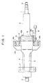
- FIG. 1 is a plan view showing a tilt telescopic type steering device for a car in a first embodiment of the present invention.
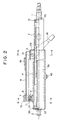
- FIG. 2 is a longitudinal vertical sectional view showing the steering device shown in FIG. 1.
- FIG. 3 is a cross-sectional view taken along the line A-A in FIG. 2.
- FIG. 4 is a cross-sectional view taken along the line B-B in FIG. 2.
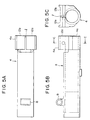
- FIG. 5A is a plan view of a lower-sided outer column.
- FIG. 5B is a side view of this outer column.
- FIG. 5C is a cross-sectional view taken along the line C-C in FIG. 5B.
- a steering shaft is, in an extensible/compressible manner, constructed of an upper shaft 1 for fixedly supporting a steering wheel (unillustrated) at a rear side end portion of the car, and a lower shaft 2 spline-fitted to this upper shaft 1.
- the steering column is slidably constructed of an upper-sided inner column 3 for rotatably supporting the upper shaft 1 at an upper side end through a ball bearing 31, and a lower-sided outer column 4 that rotatably supports the lower shaft 2 at a lower side end through a ball bearing 33 and is fitted on the upper-sided inner column 3.
- the upper shaft 1 is provided with a slip-in preventive C-ring 35 for preventing the upper shaft 1 from slipping into the inner column 3.
- the lower shaft 2 is provided with a slip-in preventive C-ring 37 for preventing the lower shaft 2 from slipping into the outer column 4.
- a bracket 6 formed with tilt adjustment grooves 5 is, as shown also in FIGS. 3 and 4, provided along the periphery of the lower-sided outer column 4.
- the bracket 6 has a flange 6a to be connected to the car body on the rear side of the car, taking an inverted U-shape directed downwards on the whole.
- the bracket 6 is also formed integrally with opposed side plate members 6b, 6c.
- a separate lower bracket 7 is so provided as to embrace the car-body-sided bracket 6.
- the lower bracket 7 includes an upper plate member 7a to be connected to the car body, and an opposed side plate members 7b, 7c, directed downwards, for holding the opposed side plate members 6b, 6c of the bracket 6 in a way of coming into contact with these members 6b, 6c.
- a front end of the outer column 4 is formed integrally with a cylindrical member 8 so that two side ends thereof are in contact with the insides of the opposed side plate members 6b, 6c of the bracket 6.
- a tilt center bolt 10 is inserted through the opposed side plate members 7b, 7c of the lower bracket 7, the opposed side plate members 6b, 6c of the bracket 6 and the cylindrical member 8 via a spacer cylinder 9, and is fastened by a nut 10a.
- the lower-sided outer column 4 is thereby capable of tilting about this tilt center bolt 10.
- the lower bracket 7 is, as shown in FIG. 2, formed with a come-off open slit 11 used for the tilt center bolt 10 to come off when collapsed upon a secondary collision.
- the lower-sided outer column 4 extends backward up to such a position as to cover almost all the fitting portion between the upper shaft 1 and the lower shaft 2, and has integrally, on a more rear side than this fitting portion, an outer jacket member 4a over a range of a certain length.
- the outer jacket member 4a is formed with a slitting 1 extending in an axial direction at the center of an upper portion thereof.
- the outer jacket member 4a is also provided with a pair of clamp members 12a, 12b for clamping the upper-sided inner column 3 so as to hold this column 3.
- Each of the clamp members 12a, 12b has an inner peripheral surface taking a configuration suited to an outer peripheral surface of the inner column 3, and an outside surface in contact with the inside of the car body sided bracket 6.
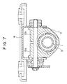
- each of the clamp members 12a, 12b be, it is desirable, brought in contact over 180° or greater in the peripheral direction with the outer peripheral surface of the inner column 3. Further, as shown in FIG.7, the inner peripheral surface thereof may be brought in contact therewith in at least three portions of the periphery.
- a fastening bolt 13 penetrates the clamp members 12a, 12b. A screw portion of this fastening bolt 13 is screwed into a fastening nut 14 and a lock nut 15 as well.
- the head of this fastening bolt 13 is fitted with an operation lever 16 and is provided with a cam lock mechanism.
- This cam lock mechanism is constructed of a fist cam member 17 rotating together with the operation lever 16, and a non-rotational second cam member 18 moving in the axial direction while engaging with a crest or bottom of the first cam member 17 with the rotation of this first cam member 17 and thus locking or unlocking.
- the first cam member 17 is structured so that a protrusion 17a of the first cam member 17 is fitted to the operation lever, whereby the first cam member 17 is capable of rotating integrally with the operation lever 16.
- the second cam member 18 is structured so that a protrusion 18a of the second cam member 18 is fitted in the tilt adjustment groove 5, whereby the second cam member 18 is always kept incapable of rotation.
- the flange 6a of the bracket 6 is provided with come-off capsules 19a, 19b used when collapsed upon the secondary collision. Namely, the bracket 6 is connected to the car body via the come-off capsules 19a, 19b.
- the operation lever 16 When making a tilt telescopic release, the operation lever 16 is rotated in a predetermined direction. Then, the first cam member 17 rotates simultaneously and engages with the bottom from the crest of the second cam member 18, and the second cam member 18 moves leftward in FIG. 3, thereby unlocking the car-body-sided bracket from the outer column 4.
- the fastening bolt 13 is moved along the tilt adjustment grooves 5, and the outer column 4 and the inner column 3 are tilted with the tilt center bolt 10 being centered, thus making it possible to adjust the steering wheel (unillustrated) at a desired tilt angle.
- the upper-sided inner column 3 When making a telescopic adjustment, the upper-sided inner column 3 is slid in the axial direction with respect to the lower-sided outer column 4, whereby the steering wheel (unillustrated) can be adjusted to a desired position in the axial direction.
- a stopper bolt 43 facing inwards in a radial direction is provided at a protruded portion on the lower side of the outer periphery of the outer column 4.
- the inner column 3 has an elongate groove 3b having a predetermined length, which is formed facing to the stopper bolt 43. An inner side end of the stopper bolt 43 engages with this elongate groove 3b, thus becoming a telescopic position adjustment stopper as well as becoming a rotation preventive member.
- the operation lever 16 When in a tilt telescopic fastening process, the operation lever 16 is rotated in the opposite direction, and simultaneously the first cam member 17 rotates and engages with the crest from the bottom of the second cam member 18, with the result that the second cam member 18 moves rightward in FIG. 3. Then, the car-body-sided bracket 6 presses the outer column 4 with the fastening bolt 13.
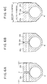
- FIG. 6A is a sectional view showing the lower-sided outer column in the first embodiment.
- FIG. 6B is a sectional view showing the lower-sided outer column in a modification of the first embodiment.
- FIG. 6C is a sectional view showing an operation of the lower-sided outer column in this modification.
- a couple of protrusions 12c, 12d are respectively provided at the portion formed with the [slitting] between the couple of clamp members 12a, 12b.
- FIG. 7 shows a second modification of the first embodiment.
- the outer periphery of the inner column 3 is brought into contact with the inner peripheries of the clamp members 12a, 12b at three areas disposed at equal angles.
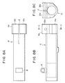
- the slitting 1 in the outer column 4 may, as shown in FIG. 8A, extend more forwards than in FIG. 5.
- the outer column 4 may be composed of castings such as an aluminum casting, a zinc casting, a magnesium-series casting and an iron-series casting.
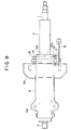
- FIG. 9 is a plan view of the tilt telescopic type steering device for the car in a second embodiment of the present invention.
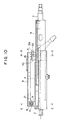
- FIG. 10 is a longitudinal vertical sectional view of the steering device shown in FIG. 9.
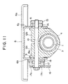
- FIG. 11 is a cross-sectional view taken along the line D-D in FIG. 10.
- FIG. 12 is a cross-sectional view taken along the line E-E in FIG. 10.
- the second embodiment uses a different come-off method when the secondary collision occurs and is substantially the same as the first embodiment discussed above other than the following configuration.
- the bracket 6 includes a rear flange 6a on the rear side of the car and a front flange 6d as integral members.
- the bracket 6 is fixedly held on the car side by these flanges so as to be impossible of coming off when collided.
- a hook 8 as a substitute for the cylindrical member in the first embodiment is formed integrally with the outer column 4.
- the steering shaft assembly consisting of the outer column 4, the inner column 3, the lower shaft 2 and the upper shaft 1, moves forwardly of the car with respect to the bracket 6 on the car side.
- FIG. 13 is a partial sectional view showing the principal components of the tilt telescopic type steering device for the car in the third embodiment of the present invention.
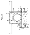
- FIG. 14 is an enlarged cross-sectional view taken along the line F-F in FIG. 13.
- the lower-sided outer column 4 to which the upper-sided inner column 3 is slidably fitted, is provided with the outer jacket configuring integrally the couple of clamp members 12a, 12b on the rear side of the car. In the third embodiment, however, a position where the clamp members clamp the inner column, is under the lower-sided outer column 4.
- a reinforcing telescopic bracket 26 formed with grooves 25 for the telescopic adjustment is provided in a position where the clamp members fasten the inner column on the car rear side of the bracket 6, in order to increase a holding force in the telescopic direction.
- the telescopic bracket 26 is fixed to the inner column 3.
- a reinforcing tilt bracket 24 having a tilt adjustment groove 23 is provided on an outer periphery of the bracket 6 to increase the holding force when tilted.
- the bracket 24 is fixed to the bracket 6.
- the operation lever 16 when making the tilt telescopic adjustment, is rotated and / or in a predetermined direction. Then, the first cam member 17 rotates simultaneously and engages with the bottom from the crest of the second cam member 18, and the second cam member 18 moves leftward in FIG. 15, thereby releasing the outer column 4 from being fastened by the car-body-sided bracket 6.
- the fastening bolt 13 is moved along the tilt adjustment groove 5 (and the tilt adjustment groove 23 of the reinforcing tilt bracket 24), and the outer column 4 and the inner column 3 are tilted, thus making it possible to adjust the steering wheel (unillustrated) at a desired tilt angle.
- the telescopic adjustment groove 25 moves along the fastening bolt 15, and the upper-sided inner column 3 is slid together with the upper shaft 1 in the axial direction with respect to the lower-sided outer column 4, whereby the steering wheel (unillustrated) can be adjusted to a desired position in the axial direction.
- the operation lever 16 is rotated in the opposite direction, and simultaneously the first cam member 17 rotates and engages with the crest from the bottom of the second cam member 18, with the result that the second cam member 18 moves rightward in FIG. 14. Then, the car-body-sided bracket 6 presses the outer column 4 with the fastening bolt 13 through the reinforcing tilt bracket 24 and the reinforcing telescopic bracket 26.
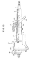
- FIG. 15 is a longitudinal vertical sectional view showing the tilt telescopic type steering device for the car in a fourth embodiment of the present invention.
- an electric power steering device 27 is provided.
- a gear box 27a of the electric power steering device 27 is formed integrally with the outer column 4, and is so supported as to be rockable about a tilt center pin 29 by a car-body-sided lower fitting bracket 28 at the front side end of the car.
- the outer jacket configuring the couple of clamp members 12a, 12b (only the member 12b is shown) that are the same as those in the first embodiment, is integrally formed behind the outer column 4 integral with the gear box 27a.
- Other configurations are-the same as those in the first through third embodiments discussed above.
- the lower-sided outer column 4 is molded integrally with the gear box of the electric power steering device 27, but may also be formed separately.
- the operation lever 16 is rotated in the fasten-canceling or releasing direction, and the inner column 3 is released from being fastened by the clamp members, whereby the telescopic adjustment and the tilt adjustment can be made.
- FIG. 16 is a plan view of the tilt telescopic type steering device for the car in a fifth embodiment of the present invention.
- FIG. 17 is a longitudinal vertical sectional view of the steering device shown in FIG. 16.
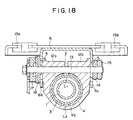
- FIG. 18 is a cross-sectional view taken along the line G-G in FIG. 17.
- the outer column 4 is a separate member from the clamp members 12a, 12b and the outer jacket 4a.
- the lower-sided outer column 4 is formed with two pieces of slittings L1, L2 extending in the axial direction, which are formed facing to each other in the radial direction at a portion fitted to and overlapped with the front side end of the upper-sided inner column with at rear side end of the outer column 4.
- the configurations and the structures of the clamp members 12a, 12b and the outer jacket 4a are the same as those in the first embodiment except that theses members are separate from the outer column 4.
- the outer jacket 4a that integrates the couple of clamp members 12a, 12b thus formed is disposed on the outer periphery of the outer column 4 on the outer peripheral side at the portion where the inner column 3 is overlapped with the outer column 4. Then, the outer jacket 4a fastens and fixes the outer column 4 directly the inner column 3 in a tilt adjustment position or in a telescopic adjustment position.
- the outer jacket 4a may be composed of castings such as an aluminum casting, a zinc casting, a magnesium-series casting and an iron-series casting. Then, the outer column 4 may be composed of a pipe material and a casting.
- FIG. 19 is a plan view of a tilt telescopic type steering device for a car in a sixth embodiment of the present invention.
- FIG. 20 is a longitudinal vertical sectional view of the steering device shown in FIG. 19.
- FIG. 21 is an enlarged vertical sectional view showing the principal components in enlargement of the steering device in FIG. 20.
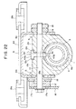
- FIG. 22 is a cross-sectional view taken along the line A-A in FIG. 20.
- Other components are the same as those in the first embodiment, and hence their repetitive explanations are omitted.
- a stopper member 44 is interposed in the gap (slitting) L between the couple clamp members 12a, 12b.
- this stopper member 44 is integrally constructed of a head 44a placed on shoulders 12c, 12d formed respectively on the clamp members 12a, 12b, and a lower end shaft member 44b fitted into a slot 3a so formed in the inner column 3 as to extend in the axial direction.
- a fastening bolt 13 tilt bolt
- a screw portion of this fastening bolt 13 is screwed into a fastening nut 14 and a lock nut 15.
- the shaft portion 44b of the stopper member 44 is movable through inside the axially-extending slot 3a of the inner column 3 and brought into contact with a side edge of the axially-extending slot 3a, whereby the stopper member 44 becomes capable of functioning as a stopper in the axial direction with respect to the inner column 3 making the telescopic slide.
- the provision of the stopper does not lead to an intricacy of the molds and eliminates the necessity of working the screw thread in a post-process.
- the stopper has an extremely simple structure, thereby making it feasible to reduce the manufacturing costs.
- the fastening bolt (tilt bolt) 13 penetrating the couple of clamp members 12a, 12b further penetrates the stopper member 44.
- This configuration induces no possibility in which the stopper member 44 comes off.
- the head 44a of the stopper member 44 comes into contact with the shoulders 12c, 12d of the clamp members 12a, 12b, and hence there is no possibility where the stopper member 44 itself rotates about the fastening bolt 13.
- the present invention is not limited to the embodiments discussed above and may be modified in a variety of forms.
- the couple of clamp members integral with or separate from the outer column are so provided as to embrace the inner column or the outer column.
- the fastening member forces the couple of clamp members to move close to each other, and the inner column or the outer column is embraced and clamped by the couple of clamp members. Accordingly, the inner column is thus directly clamped by the outer column.
Landscapes
- Engineering & Computer Science (AREA)
- Chemical & Material Sciences (AREA)
- Combustion & Propulsion (AREA)
- Transportation (AREA)
- Mechanical Engineering (AREA)
- Steering Controls (AREA)
Abstract
Description
Claims (6)
- A steering device for a car, comprising: an inner column for rotatably supporting one end of a steering shaft;an outer column, for rotatably supporting the other end of said steering shaft, in which said inner column is slidably fitted;a couple of clamp members formed integrally with said outer column and each having an embracing surface for embracing said inner column; andfastening means for making said couple of clamp members embrace and thus fasten said inner column by moving said couple of clamp members close to each other,wherein said steering shaft is moved in the axial direction by releasing the fastening by said fastening means so that a telescopic position of said steering shaft is adjustable.
- A steering device for a car according to claim 1, wherein said outer column is rotatably supported to the car body, and a tilt position of said steering shaft is adjustable when releasing the fastening by said fastening means.
- A steering device for a car, comprising:an inner column for rotatably supporting one end of a steering shaft;an outer column, for rotatably supporting the other end of said steering shaft, in which said inner column is slidably fitted;a couple of clamp members made by a casting process, disposed along an outer periphery of said outer column and each having an embracing surface for embracing said inner column; andfastening means for making said couple of clamp members embrace and thus fasten said inner column by moving said couple of clamp members close to each other,wherein said steering shaft is moved in the axial direction by releasing the fastening by said fastening means so that a telescopic position of said steering shaft is adjustable.
- A steering device for a car according to claim 3, wherein said outer column is rotatably supported to the car body, and, a tilt position of said steering shaft is adjustable when releasing the fastening by said fastening means.
- A steering device including an inner column slidably fitted within an outer column and releasable clamp means for clamping the inner column relative to the outer column when in a clamping condition and for allowing relative sliding movement between said columns when in a released condition.
- A device as claimed in claim 5, wherein said clamp means are integral with said outer column.
Priority Applications (1)
| Application Number | Priority Date | Filing Date | Title |
|---|---|---|---|
| DE60133331T DE60133331T3 (en) | 2000-02-15 | 2001-02-13 | Steering for an automobile |
Applications Claiming Priority (8)
| Application Number | Priority Date | Filing Date | Title |
|---|---|---|---|
| JP2000036936 | 2000-02-15 | ||
| JP2000036936 | 2000-02-15 | ||
| JP2000102693 | 2000-04-04 | ||
| JP2000102693 | 2000-04-04 | ||
| JP2000254210A JP4613402B2 (en) | 2000-02-15 | 2000-08-24 | Vehicle steering device |
| JP2000254210 | 2000-08-24 | ||
| JP2000312118A JP4581214B2 (en) | 2000-10-12 | 2000-10-12 | Vehicle steering device |
| JP2000312118 | 2000-10-12 |
Publications (4)
| Publication Number | Publication Date |
|---|---|
| EP1125820A2 true EP1125820A2 (en) | 2001-08-22 |
| EP1125820A3 EP1125820A3 (en) | 2003-01-22 |
| EP1125820B1 EP1125820B1 (en) | 2008-03-26 |
| EP1125820B2 EP1125820B2 (en) | 2012-07-11 |
Family
ID=27481036
Family Applications (1)
| Application Number | Title | Priority Date | Filing Date |
|---|---|---|---|
| EP01301278A Expired - Lifetime EP1125820B2 (en) | 2000-02-15 | 2001-02-13 | Steering device for car |
Country Status (3)
| Country | Link |
|---|---|
| US (1) | US6467807B2 (en) |
| EP (1) | EP1125820B2 (en) |
| DE (1) | DE60133331T3 (en) |
Cited By (22)
| Publication number | Priority date | Publication date | Assignee | Title |
|---|---|---|---|---|
| EP1661789A4 (en) * | 2003-09-01 | 2006-11-29 | Nsk Ltd | Position adjustment type steering column device for vehicles |
| EP1726508A1 (en) * | 2005-05-26 | 2006-11-29 | Delphi Technologies, Inc. | Clamp for friction lock mechanism on steering column |
| EP1612120A4 (en) * | 2003-03-26 | 2007-01-31 | Nsk Ltd | Steering device for motor vehicle |
| EP1529714A3 (en) * | 2003-11-07 | 2007-07-04 | NSK Ltd., | Steering column clamping apparatus |
| EP1645486A4 (en) * | 2003-07-16 | 2007-11-28 | Nsk Ltd | Steering device |
| CN102700598A (en) * | 2011-03-28 | 2012-10-03 | 株式会社山田制作所 | Steering apparatus |
| US8366149B2 (en) | 2008-07-24 | 2013-02-05 | Thyssenkrup Presta Aktiengesellschaft | Steering column for a motor vehicle |
| US8474869B2 (en) | 2009-12-16 | 2013-07-02 | Thyssenkrupp Presta Aktiengesellschaft | Steering column for a motor vehicle |
| CN103328306A (en) * | 2011-12-20 | 2013-09-25 | 日本精工株式会社 | Steering device |
| EP2647545A1 (en) * | 2012-04-06 | 2013-10-09 | Yamada Manufacturing Co., Ltd. | Steering device |
| CN103754254A (en) * | 2014-02-13 | 2014-04-30 | 安徽江淮汽车股份有限公司 | Four-way adjustable crumpling energy absorption steering column |
| US8827311B2 (en) | 2010-05-25 | 2014-09-09 | Thyssenkrupp Presta Aktiengesellschaft | Spring element |
| CN104071207A (en) * | 2013-03-28 | 2014-10-01 | 株式会社昭和 | Steering device |
| US8894097B2 (en) | 2010-06-28 | 2014-11-25 | Thyssenkrupp Presta Aktiengesellschaft | Adjustable steering column for a motor vehicle |
| EP2602170A4 (en) * | 2010-08-04 | 2015-03-18 | Nsk Ltd | STEERING APPARATUS |
| US8991862B2 (en) | 2011-10-19 | 2015-03-31 | Thyssenkrupp Presta Aktiengesellschaft | Steering column for a motor vehicle |
| US9010807B2 (en) | 2011-10-19 | 2015-04-21 | Thyssenkrupp Presta Aktiengesellschaft | Steering shaft bearing unit for rotatably mounting a steering shaft |
| US9022427B2 (en) | 2011-10-19 | 2015-05-05 | Thyssenkrupp Presta Aktiengeesllscahft | Steering shaft bearing unit |
| US9233706B2 (en) | 2011-10-19 | 2016-01-12 | Thyssenkrupp Presta Aktiengesellschaft | Steering shaft bearing unit for rotatably mounting a steering shaft |
| US9233707B2 (en) | 2010-12-15 | 2016-01-12 | Thyssenkrupp Presta Aktiengesellschaft | Steering column for a motor vehicle |
| DE102015002889B3 (en) * | 2015-03-09 | 2016-05-12 | Thyssenkrupp Ag | Adjustable steering column with improved rigidity |
| WO2018160788A1 (en) * | 2017-03-02 | 2018-09-07 | Nsk Americas, Inc. | Steering column telescope travel stop |
Families Citing this family (84)
| Publication number | Priority date | Publication date | Assignee | Title |
|---|---|---|---|---|
| DE10039794A1 (en) * | 2000-08-16 | 2002-02-28 | Daimler Chrysler Ag | Position adjustment device for a steering column |
| FR2818602B1 (en) * | 2000-12-26 | 2003-03-28 | Nacam | DEVICE FOR TIGHTENING AN ELEMENT ADJUSTABLE TO A SUPPORT ASSEMBLY |
| JP3886766B2 (en) * | 2001-01-11 | 2007-02-28 | 富士機工株式会社 | Tilt and telescopic steering column device |
| JP3738200B2 (en) * | 2001-06-27 | 2006-01-25 | 光洋精工株式会社 | Shock absorbing steering device |
| JP2003127874A (en) * | 2001-10-23 | 2003-05-08 | Fuji Kiko Co Ltd | Shock absorbing tilt steering column |
| KR100482056B1 (en) * | 2001-12-19 | 2005-04-13 | 현대자동차주식회사 | a knee protecting apparatus in vehicles |
| JP4147579B2 (en) * | 2002-01-17 | 2008-09-10 | 日本精工株式会社 | Steering device |
| US7024230B2 (en) * | 2002-02-22 | 2006-04-04 | Kyocera-Wireless Corp | Accessory interface system |
| US7028967B2 (en) * | 2002-05-01 | 2006-04-18 | Xerxes Corporation | Tank retaining system |
| US6948741B2 (en) * | 2002-05-09 | 2005-09-27 | Delphi Technologies, Inc. | Telescoping steering column assembly |
| JP4192891B2 (en) * | 2002-05-10 | 2008-12-10 | 日本精工株式会社 | Steering device |
| DE60332114D1 (en) * | 2002-07-10 | 2010-05-27 | Nsk Ltd | VEHICLE SHOCK ABSORPTION COLUMN DEVICE |
| JP4179049B2 (en) * | 2002-07-16 | 2008-11-12 | 日本精工株式会社 | Position-adjustable steering column device |
| EP1535824B1 (en) * | 2002-07-25 | 2008-08-27 | Nsk Ltd. | Steering column device |
| JPWO2004022410A1 (en) * | 2002-09-04 | 2005-12-22 | 日本精工株式会社 | Vehicle-adjustable steering column device |
| JP2004155268A (en) | 2002-11-05 | 2004-06-03 | Nsk Ltd | Telescopic steering column device |
| US7125048B2 (en) * | 2002-11-06 | 2006-10-24 | Lear Corporation | Dampener |
| JPWO2004043766A1 (en) * | 2002-11-11 | 2006-03-09 | 日本精工株式会社 | Vehicle steering device |
| JP4062082B2 (en) * | 2002-12-12 | 2008-03-19 | 日本精工株式会社 | Steering column device |
| JP2004203164A (en) * | 2002-12-25 | 2004-07-22 | Fuji Kiko Co Ltd | Impact absorbing structure of vehicle steering system |
| JP4308040B2 (en) * | 2003-06-05 | 2009-08-05 | 日本精工株式会社 | Steering device |
| JP2005014681A (en) * | 2003-06-24 | 2005-01-20 | Nsk Ltd | Steering column device for vehicle |
| JP4390134B2 (en) * | 2003-11-05 | 2009-12-24 | 日本精工株式会社 | Steering device |
| US7178832B2 (en) * | 2004-01-06 | 2007-02-20 | Delphi Technologies, Inc. | Telescoping steering column assembly with brake |
| US20050200111A1 (en) * | 2004-03-11 | 2005-09-15 | Cymbal William D. | Multi piece bearing for telescoping steering column assembly |
| US7516985B2 (en) * | 2004-03-11 | 2009-04-14 | Delphi Technologies, Inc. | Multi piece bearing for telescoping steering column assembly |
| JP4210853B2 (en) * | 2004-06-16 | 2009-01-21 | 三菱自動車工業株式会社 | Vehicle steering support device |
| CN100469638C (en) * | 2004-07-27 | 2009-03-18 | 日本精工株式会社 | steering column unit |
| JP4609203B2 (en) * | 2004-08-05 | 2011-01-12 | 日本精工株式会社 | Steering column device |
| US20060169089A1 (en) * | 2005-02-03 | 2006-08-03 | Delphi Technologies, Inc. | Rake and telescope mechanism |
| US20060207378A1 (en) * | 2005-03-17 | 2006-09-21 | Delphi Technologies, Inc. | Mounting structure for steering column |
| JP4373950B2 (en) * | 2005-03-31 | 2009-11-25 | 株式会社山田製作所 | Steering handle position adjustment device |
| US7503234B2 (en) * | 2005-05-26 | 2009-03-17 | Delphi Technologies, Inc. | One lever tilt and telescope mechanism |
| DE102005034952B3 (en) * | 2005-07-22 | 2007-02-22 | Thyssenkrupp Automotive Ag | Adjustable steering column for a motor vehicle |
| US7699344B2 (en) * | 2006-02-21 | 2010-04-20 | Nsk Ltd. | Steering device |
| US20070245845A1 (en) * | 2006-04-20 | 2007-10-25 | Ridgway Jason R | Steering column assembly for a vehicle |
| JP2007314122A (en) * | 2006-05-29 | 2007-12-06 | Jtekt Corp | Electric power steering device |
| US7625009B2 (en) * | 2007-02-06 | 2009-12-01 | Gm Global Technology Operations, Inc. | Collapsible steering column support |
| US7743681B2 (en) * | 2007-04-04 | 2010-06-29 | Gm Global Technology Operations, Inc. | Steering column assembly having an actuation mechanism for telescoping and tilting movement |
| JP5092880B2 (en) * | 2007-05-17 | 2012-12-05 | 日本精工株式会社 | Steering device |
| KR100980959B1 (en) * | 2007-07-18 | 2010-09-07 | 현대자동차주식회사 | Push-pull tilt lever of vehicle steering |
| GB0714161D0 (en) * | 2007-07-20 | 2007-08-29 | Trw Ltd | Steering column assembly |
| GB2451506B (en) * | 2007-08-02 | 2011-12-28 | Ford Global Tech Llc | An adjustable steering column assembly for a motor vehicle |
| JP2009119999A (en) * | 2007-11-14 | 2009-06-04 | Toyota Motor Corp | Vehicle steering column device |
| US7882761B2 (en) * | 2008-01-05 | 2011-02-08 | Nexteer (Beijing) Technology Co., Ltd. | Adjustable steering column assembly with compressive locking mechanism |
| US8100617B2 (en) * | 2008-01-22 | 2012-01-24 | Nexteer (Beijing) Technology Co., Ltd. | Fastener system with frangible member |
| US7874228B2 (en) * | 2008-02-14 | 2011-01-25 | Nexteer (Beijing) Technology Co., Ltd. | Non-translating telescopic rake pivot for steering column assembly |
| DE102008016742B4 (en) | 2008-03-31 | 2010-01-14 | Thyssenkrupp Presta Ag | Steering column for a motor vehicle |
| US7914043B2 (en) * | 2008-04-07 | 2011-03-29 | Nexteer (Beijing) Technology Co., Ltd. | Adjustable steering column assembly for a vehicle |
| CN102009683A (en) * | 2009-05-29 | 2011-04-13 | 通用汽车环球科技运作公司 | Collapsible steering column assembly |
| JP5428582B2 (en) * | 2009-06-30 | 2014-02-26 | 日本精工株式会社 | Steering device |
| KR101268248B1 (en) * | 2009-07-09 | 2013-05-31 | 주식회사 만도 | Steering Column for Vehicle |
| JP5662115B2 (en) * | 2010-01-20 | 2015-01-28 | 株式会社山田製作所 | Steering device |
| JP2011157015A (en) * | 2010-02-02 | 2011-08-18 | Fuji Kiko Co Ltd | Steering column device |
| KR20110096805A (en) * | 2010-02-23 | 2011-08-31 | 주식회사 만도 | Steering column of automobile and steering apparatus of automobile including same |
| JP5459272B2 (en) * | 2010-07-06 | 2014-04-02 | 日本精工株式会社 | Steering device |
| JP5723226B2 (en) * | 2011-06-07 | 2015-05-27 | 株式会社山田製作所 | Steering device |
| KR20130027122A (en) | 2011-09-07 | 2013-03-15 | 주식회사 만도 | Steering column for vehicle and steering apparatus for vehicle having the same |
| US20130160594A1 (en) * | 2011-12-21 | 2013-06-27 | Nexteer (Beijing) Technology Co., Ltd. | Telescoping Jacket Interface Mechanism |
| DE102012008836A1 (en) * | 2012-04-28 | 2013-10-31 | Daimler Ag | Steering column for a motor vehicle |
| JP2014058200A (en) * | 2012-09-14 | 2014-04-03 | Yamada Seisakusho Co Ltd | Steering device |
| US20140137693A1 (en) * | 2012-11-19 | 2014-05-22 | Donald A. Buzzard | On center rake and telescope clamp for an adjustable steering column |
| JP5886805B2 (en) * | 2013-09-03 | 2016-03-16 | 株式会社山田製作所 | Steering device |
| EP3052370B1 (en) | 2013-10-04 | 2017-06-14 | NSK Americas, Inc. | Collapsible steering column assembly |
| JP5983891B2 (en) | 2013-10-30 | 2016-09-06 | 日本精工株式会社 | Steering device |
| JP5971429B2 (en) | 2013-10-30 | 2016-08-17 | 日本精工株式会社 | Steering device |
| JP5987994B2 (en) | 2013-10-30 | 2016-09-07 | 日本精工株式会社 | Steering device |
| CN105473414B (en) | 2013-10-30 | 2017-04-05 | 日本精工株式会社 | Steering device |
| WO2015145845A1 (en) * | 2014-03-26 | 2015-10-01 | 日本精工株式会社 | Position adjustment device for steering wheel |
| DE102014009517B3 (en) * | 2014-06-25 | 2015-09-17 | Audi Ag | steering system |
| US9555825B2 (en) * | 2014-11-11 | 2017-01-31 | Trw Automotive U.S. Llc | Steering column |
| WO2017135384A1 (en) * | 2016-02-04 | 2017-08-10 | 日本精工株式会社 | Steering apparatus |
| GB201612606D0 (en) * | 2016-07-20 | 2016-08-31 | Trw Ltd | A steering column assembly |
| US11518428B2 (en) | 2018-08-30 | 2022-12-06 | Nsk Americas, Inc. | Steering column breakaway and energy absorption apparatus |
| JP7345737B2 (en) | 2019-05-30 | 2023-09-19 | 日本精工株式会社 | Steering column anti-rotation device |
| CN113939439B (en) | 2019-05-31 | 2024-04-12 | Nsk有限公司 | Forced locking driving mechanism for steering column |
| JP2021020505A (en) * | 2019-07-25 | 2021-02-18 | 富士機工株式会社 | Steering column device |
| JP7173451B2 (en) | 2019-08-20 | 2022-11-16 | 日本精工株式会社 | Steering column telescopic positive locking and unlocking device |
| CN112065859B (en) * | 2020-09-09 | 2022-07-01 | 山东兴和特种材料有限公司 | Wear-resisting bush component |
| JP2024535219A (en) | 2021-09-16 | 2024-09-30 | エヌエスケイ ステアリング システムズ アメリカ インコーポレイテッド | Steering column shroud breakaway interface |
| US20260184364A1 (en) | 2022-12-07 | 2026-07-02 | Nsk Steering Systems America, Inc. | Breakaway device for an automotive steering column |
| WO2025199180A1 (en) | 2024-03-19 | 2025-09-25 | Nsk Steering Systems America, Inc. | Positive lock and breakaway device |
| KR20250160749A (en) * | 2024-05-07 | 2025-11-14 | 에이치엘만도 주식회사 | Steering apparatus for vehicle |
| WO2025250867A1 (en) | 2024-05-31 | 2025-12-04 | Nsk Steering Systems America, Inc. | Steering column rotational fixer device |
Family Cites Families (53)
| Publication number | Priority date | Publication date | Assignee | Title |
|---|---|---|---|---|
| US3955439A (en) † | 1974-09-30 | 1976-05-11 | Eaton Corporation | Positioning device for adjustable steering column |
| FR2360454A1 (en) † | 1976-08-05 | 1978-03-03 | Chrysler France | Adjustable car steering column assembly - has movable steering column support and fixed support on car, both supports having slots for adjusting rake and length |
| IT1091449B (en) † | 1977-11-09 | 1985-07-06 | Fiat Veicoli Ind | DEVICE FOR THE REGISTRATION OF THE STEERING SETUP OF MOTOR VEHICLES |
| GB1572965A (en) † | 1978-02-23 | 1980-08-06 | Ford Motor Co | Steering column assemblies |
| BG30829A1 (en) † | 1980-02-26 | 1981-09-15 | Petrov | Wheel column |
| JPS5845171A (en) | 1981-09-11 | 1983-03-16 | 旭硝子株式会社 | Hot melt refractories of spinel-periclase tissue |
| GB2116496B (en) | 1982-03-09 | 1985-08-14 | Gen Motors Ltd | Steering column mounting assemblies |
| US4481838A (en) * | 1982-04-19 | 1984-11-13 | Douglas Components Corporation | Adjustable steering shaft |
| US4475744A (en) * | 1983-05-27 | 1984-10-09 | Douglas Components Corporation | Telescoping steering shaft with adjusted lash |
| DE3421273C2 (en) * | 1983-06-11 | 1987-01-22 | Aisin Seiki K.K., Kariya, Aichi | Shaft bushing unit |
| DE3324835A1 (en) | 1983-07-09 | 1985-01-17 | Cassella Ag, 6000 Frankfurt | CROSSLINKED COPOLYMER, PROCESS FOR PRODUCING IT AND ITS USE AS SORPENT |
| DE3619125C1 (en) † | 1986-06-06 | 1987-10-22 | Daimler Benz Ag | Receiving device for an adjustable steering column of a motor vehicle |
| US5009121A (en) * | 1989-07-07 | 1991-04-23 | Nippon Seiko Kabushiki Kaisha | Telescopic steering column device |
| JPH03128564A (en) | 1989-10-13 | 1991-05-31 | Nec Corp | Facsimile receiver |
| US5117707A (en) † | 1990-02-23 | 1992-06-02 | Fuji Kiko Company, Limited | Tilting steering column |
| JPH03128564U (en) * | 1990-04-10 | 1991-12-25 | ||
| US5090730A (en) * | 1991-01-23 | 1992-02-25 | Itt Corporation | Vehicle steering column apparatus |
| JP2989680B2 (en) * | 1991-02-15 | 1999-12-13 | 株式会社山田製作所 | Tilt and telescopic steering system |
| US5476284A (en) † | 1991-09-11 | 1995-12-19 | Itt Corporation | Energy absorbing collapsible steering apparatus |
| FR2688182B1 (en) † | 1992-03-04 | 1994-06-10 | Ecia Equip Composants Ind Auto | STEERING COLUMN ADJUSTABLE IN POSITION FOR MOTOR VEHICLE. |
| FR2701682B1 (en) † | 1993-02-17 | 1995-05-24 | Peugeot | Retractable steering column assembly in the event of an impact. |
| US5439252A (en) * | 1993-04-22 | 1995-08-08 | Trw Inc. | Dual pivot steering column |
| FR2714648B1 (en) † | 1994-01-06 | 1996-03-15 | Nacam | Axially-held energy absorption device for a motor vehicle steering column. |
| US5722299A (en) † | 1994-06-30 | 1998-03-03 | Fuji Kiko Co., Ltd. | Adjustable steering column assembly for a vehicle |
| JP3335485B2 (en) | 1994-09-13 | 2002-10-15 | 富士機工株式会社 | Vehicle steering column |
| US5520416A (en) * | 1994-10-03 | 1996-05-28 | Ford Motor Company | Power tilt, telescoping and internally collapsible steering column |
| US5555772A (en) * | 1994-10-31 | 1996-09-17 | General Motors Corporation | Position control apparatus for steering column |
| JPH08175400A (en) * | 1994-12-21 | 1996-07-09 | Toyota Motor Corp | Telescopic steering device |
| FR2729936B1 (en) † | 1995-01-30 | 1997-04-18 | Sipa Roller | SECURITY SYSTEM FOR LOAD SEPARATION DEVICE IN A DYNAMIC STORAGE CORRIDOR |
| JPH08225079A (en) † | 1995-02-20 | 1996-09-03 | Nippon Seiko Kk | Shock absorption type steering column |
| US5606892A (en) * | 1995-03-31 | 1997-03-04 | Ford Motor Company | Modular steering column assembly |
| US5527068A (en) * | 1995-05-30 | 1996-06-18 | General Motors Corporation | Motor vehicle steering column |
| DE19531278C1 (en) † | 1995-08-25 | 1997-01-30 | Daimler Benz Ag | Joint for the pivot mounting of a tubular casing of an inclinable steering column on a tubular casing suspension of a vehicle |
| US5697825A (en) | 1995-09-29 | 1997-12-16 | Micron Display Technology, Inc. | Method for evacuating and sealing field emission displays |
| FR2742718B1 (en) * | 1995-12-20 | 1998-03-06 | Ecia Equip Composants Ind Auto | STEERING COLUMN SET ADJUSTABLE TO POSITION AND SHOCK ENERGY ABSORPTION, PARTICULARLY FOR MOTOR VEHICLE |
| AU698974B2 (en) * | 1996-05-14 | 1998-11-12 | Trw Inc. | Steering column |
| US5711189A (en) * | 1996-05-20 | 1998-01-27 | Trw Inc. | Steering column |
| US5820163A (en) * | 1996-07-08 | 1998-10-13 | Ford Global Technologies, Inc. | Tilting, telescoping and energy absorbing steering column |
| DE19643203A1 (en) † | 1996-10-19 | 1998-04-23 | Supervis Ets | Device on a steering column for motor vehicles for length and / or height or inclination adjustment |
| DE19737034B4 (en) † | 1997-08-26 | 2006-09-07 | C. Rob. Hammerstein Gmbh & Co. Kg | Steering module of a motor vehicle with both in their inclination and in length adjustable steering column |
| US5979265A (en) † | 1997-09-11 | 1999-11-09 | Mando Machinery Corporation | Tilting and telescopic structure for steering columns |
| GB2329454B (en) † | 1997-09-19 | 2001-08-15 | Nastech Europ Ltd | Adjustable steering column mounting |
| US5979938A (en) * | 1997-12-15 | 1999-11-09 | General Motors Corporation | Adjustable steering column for motor vehicle |
| JPH11278283A (en) | 1998-03-31 | 1999-10-12 | Fuji Kiko Co Ltd | Automotive steering column |
| US6189405B1 (en) * | 1998-04-30 | 2001-02-20 | Kabushiki Kaisha Yamada Seisa Kusho | Position adjusting device for steering wheels |
| US6019391A (en) * | 1998-05-04 | 2000-02-01 | General Motors Corporation | Steering column for motor vehicle |
| US6036228A (en) † | 1998-05-04 | 2000-03-14 | General Motors Corporation | Adjustable steering column for motor vehicle |
| US6167777B1 (en) * | 1998-12-14 | 2001-01-02 | Chrysler Corporation | Tiltable steering column lock mechanism |
| GB9912346D0 (en) † | 1999-05-26 | 1999-07-28 | Nastech Europ Ltd | Collapsible steering column assembly for a vehicle |
| US6324935B1 (en) * | 1999-11-22 | 2001-12-04 | Daimlerchrysler Corporation | Collapsible steering assembly |
| JP3783524B2 (en) † | 2000-05-16 | 2006-06-07 | トヨタ自動車株式会社 | Tilt and telescopic steering device |
| FR2850934B1 (en) † | 2003-02-10 | 2005-04-08 | Nacam | PIVOT SLIDING AN ADJUSTABLE STEERING COLUMN OF A MOTOR VEHICLE |
| FR2877303B1 (en) † | 2004-10-28 | 2007-02-09 | Faurecia Interieur Ind Snc | CONNECTING DEVICE BETWEEN THE STEERING COLUMN AND THE BODY OF A MOTOR VEHICLE. |
-
2001
- 2001-02-13 EP EP01301278A patent/EP1125820B2/en not_active Expired - Lifetime
- 2001-02-13 DE DE60133331T patent/DE60133331T3/en not_active Expired - Lifetime
- 2001-02-14 US US09/782,523 patent/US6467807B2/en not_active Expired - Lifetime
Cited By (30)
| Publication number | Priority date | Publication date | Assignee | Title |
|---|---|---|---|---|
| EP1612120A4 (en) * | 2003-03-26 | 2007-01-31 | Nsk Ltd | Steering device for motor vehicle |
| US7401813B2 (en) | 2003-03-26 | 2008-07-22 | Nsk Ltd. | Steering apparatus for motor vehicle |
| EP1645486A4 (en) * | 2003-07-16 | 2007-11-28 | Nsk Ltd | Steering device |
| US7413222B2 (en) | 2003-09-01 | 2008-08-19 | Nsk Ltd. | Position adjustment type steering column device for vehicles |
| EP1661789A4 (en) * | 2003-09-01 | 2006-11-29 | Nsk Ltd | Position adjustment type steering column device for vehicles |
| EP1529714A3 (en) * | 2003-11-07 | 2007-07-04 | NSK Ltd., | Steering column clamping apparatus |
| EP1726508A1 (en) * | 2005-05-26 | 2006-11-29 | Delphi Technologies, Inc. | Clamp for friction lock mechanism on steering column |
| US7516682B2 (en) | 2005-05-26 | 2009-04-14 | Delphi Technologies, Inc. | Clamp for friction lock mechanism on steering column |
| US8366149B2 (en) | 2008-07-24 | 2013-02-05 | Thyssenkrup Presta Aktiengesellschaft | Steering column for a motor vehicle |
| US8474869B2 (en) | 2009-12-16 | 2013-07-02 | Thyssenkrupp Presta Aktiengesellschaft | Steering column for a motor vehicle |
| US8827311B2 (en) | 2010-05-25 | 2014-09-09 | Thyssenkrupp Presta Aktiengesellschaft | Spring element |
| US8894097B2 (en) | 2010-06-28 | 2014-11-25 | Thyssenkrupp Presta Aktiengesellschaft | Adjustable steering column for a motor vehicle |
| EP2602170A4 (en) * | 2010-08-04 | 2015-03-18 | Nsk Ltd | STEERING APPARATUS |
| US9233707B2 (en) | 2010-12-15 | 2016-01-12 | Thyssenkrupp Presta Aktiengesellschaft | Steering column for a motor vehicle |
| CN102700598A (en) * | 2011-03-28 | 2012-10-03 | 株式会社山田制作所 | Steering apparatus |
| US8991862B2 (en) | 2011-10-19 | 2015-03-31 | Thyssenkrupp Presta Aktiengesellschaft | Steering column for a motor vehicle |
| US9010807B2 (en) | 2011-10-19 | 2015-04-21 | Thyssenkrupp Presta Aktiengesellschaft | Steering shaft bearing unit for rotatably mounting a steering shaft |
| US9233706B2 (en) | 2011-10-19 | 2016-01-12 | Thyssenkrupp Presta Aktiengesellschaft | Steering shaft bearing unit for rotatably mounting a steering shaft |
| US9022427B2 (en) | 2011-10-19 | 2015-05-05 | Thyssenkrupp Presta Aktiengeesllscahft | Steering shaft bearing unit |
| CN103328306A (en) * | 2011-12-20 | 2013-09-25 | 日本精工株式会社 | Steering device |
| CN103328306B (en) * | 2011-12-20 | 2016-02-10 | 日本精工株式会社 | Steering hardware |
| US8967017B2 (en) | 2012-04-06 | 2015-03-03 | Yamada Manufacturing Co., Ltd. | Steering device |
| EP2647545A1 (en) * | 2012-04-06 | 2013-10-09 | Yamada Manufacturing Co., Ltd. | Steering device |
| CN104071207A (en) * | 2013-03-28 | 2014-10-01 | 株式会社昭和 | Steering device |
| CN104071207B (en) * | 2013-03-28 | 2017-06-30 | 株式会社昭和 | Transfer |
| CN103754254A (en) * | 2014-02-13 | 2014-04-30 | 安徽江淮汽车股份有限公司 | Four-way adjustable crumpling energy absorption steering column |
| CN103754254B (en) * | 2014-02-13 | 2016-02-10 | 安徽江淮汽车股份有限公司 | The crumple energy-absorbing steering tube column that four-way is adjustable |
| DE102015002889B3 (en) * | 2015-03-09 | 2016-05-12 | Thyssenkrupp Ag | Adjustable steering column with improved rigidity |
| US10137924B2 (en) | 2015-03-09 | 2018-11-27 | Thyssenkrupp Presta Ag | Adjustable steering column having improved rigidity |
| WO2018160788A1 (en) * | 2017-03-02 | 2018-09-07 | Nsk Americas, Inc. | Steering column telescope travel stop |
Also Published As
| Publication number | Publication date |
|---|---|
| EP1125820A3 (en) | 2003-01-22 |
| EP1125820B1 (en) | 2008-03-26 |
| US20010019205A1 (en) | 2001-09-06 |
| DE60133331T2 (en) | 2009-04-23 |
| DE60133331D1 (en) | 2008-05-08 |
| US6467807B2 (en) | 2002-10-22 |
| EP1125820B2 (en) | 2012-07-11 |
| DE60133331T3 (en) | 2012-12-06 |
Similar Documents
| Publication | Publication Date | Title |
|---|---|---|
| US6467807B2 (en) | Steering device for car | |
| KR101031627B1 (en) | Steering column unit | |
| CN100364831C (en) | steering gear | |
| JP4541297B2 (en) | Vehicle steering device | |
| US11148703B2 (en) | Support bracket for steering apparatus and steering apparatus | |
| EP1223096A1 (en) | Steering column assembly for a vehicle | |
| JP7424306B2 (en) | steering column device | |
| JP5811232B2 (en) | Vehicle steering device | |
| JP4470302B2 (en) | Vehicle steering device | |
| CN110450847B (en) | Steering device | |
| EP3865373B1 (en) | Steering column device | |
| JP2002104205A (en) | Vehicle steering system | |
| JP7347139B2 (en) | steering device | |
| JP2023169007A (en) | steering device | |
| JP2005335532A5 (en) | ||
| JPH04112168U (en) | Telescoping steering column device | |
| JP2005335532A (en) | Steering column device |
Legal Events
| Date | Code | Title | Description |
|---|---|---|---|
| PUAI | Public reference made under article 153(3) epc to a published international application that has entered the european phase |
Free format text: ORIGINAL CODE: 0009012 |
|
| AK | Designated contracting states |
Kind code of ref document: A2 Designated state(s): AT BE CH CY DE DK ES FI FR GB GR IE IT LI LU MC NL PT SE TR |
|
| AX | Request for extension of the european patent |
Free format text: AL;LT;LV;MK;RO;SI |
|
| PUAL | Search report despatched |
Free format text: ORIGINAL CODE: 0009013 |
|
| AK | Designated contracting states |
Kind code of ref document: A3 Designated state(s): AT BE CH CY DE DK ES FI FR GB GR IE IT LI LU MC NL PT SE TR |
|
| AX | Request for extension of the european patent |
Free format text: AL;LT;LV;MK;RO;SI |
|
| 17P | Request for examination filed |
Effective date: 20030328 |
|
| 17Q | First examination report despatched |
Effective date: 20030527 |
|
| AKX | Designation fees paid |
Designated state(s): DE GB |
|
| GRAP | Despatch of communication of intention to grant a patent |
Free format text: ORIGINAL CODE: EPIDOSNIGR1 |
|
| GRAS | Grant fee paid |
Free format text: ORIGINAL CODE: EPIDOSNIGR3 |
|
| GRAA | (expected) grant |
Free format text: ORIGINAL CODE: 0009210 |
|
| AK | Designated contracting states |
Kind code of ref document: B1 Designated state(s): DE GB |
|
| REG | Reference to a national code |
Ref country code: GB Ref legal event code: FG4D |
|
| REF | Corresponds to: |
Ref document number: 60133331 Country of ref document: DE Date of ref document: 20080508 Kind code of ref document: P |
|
| PLBI | Opposition filed |
Free format text: ORIGINAL CODE: 0009260 |
|
| 26 | Opposition filed |
Opponent name: THYSSENKRUPP PRESTA AKTIENGESELLSCHAFT Effective date: 20081219 |
|
| PLAX | Notice of opposition and request to file observation + time limit sent |
Free format text: ORIGINAL CODE: EPIDOSNOBS2 |
|
| PLAF | Information modified related to communication of a notice of opposition and request to file observations + time limit |
Free format text: ORIGINAL CODE: EPIDOSCOBS2 |
|
| PLBB | Reply of patent proprietor to notice(s) of opposition received |
Free format text: ORIGINAL CODE: EPIDOSNOBS3 |
|
| APBM | Appeal reference recorded |
Free format text: ORIGINAL CODE: EPIDOSNREFNO |
|
| APBP | Date of receipt of notice of appeal recorded |
Free format text: ORIGINAL CODE: EPIDOSNNOA2O |
|
| APAH | Appeal reference modified |
Free format text: ORIGINAL CODE: EPIDOSCREFNO |
|
| APBQ | Date of receipt of statement of grounds of appeal recorded |
Free format text: ORIGINAL CODE: EPIDOSNNOA3O |
|
| APBU | Appeal procedure closed |
Free format text: ORIGINAL CODE: EPIDOSNNOA9O |
|
| PUAH | Patent maintained in amended form |
Free format text: ORIGINAL CODE: 0009272 |
|
| STAA | Information on the status of an ep patent application or granted ep patent |
Free format text: STATUS: PATENT MAINTAINED AS AMENDED |
|
| 27A | Patent maintained in amended form |
Effective date: 20120711 |
|
| AK | Designated contracting states |
Kind code of ref document: B2 Designated state(s): DE GB |
|
| REG | Reference to a national code |
Ref country code: DE Ref legal event code: R102 Ref document number: 60133331 Country of ref document: DE Effective date: 20120711 |
|
| PGFP | Annual fee paid to national office [announced via postgrant information from national office to epo] |
Ref country code: DE Payment date: 20200129 Year of fee payment: 20 Ref country code: GB Payment date: 20200206 Year of fee payment: 20 |
|
| REG | Reference to a national code |
Ref country code: DE Ref legal event code: R071 Ref document number: 60133331 Country of ref document: DE |
|
| REG | Reference to a national code |
Ref country code: GB Ref legal event code: PE20 Expiry date: 20210212 |
|
| PG25 | Lapsed in a contracting state [announced via postgrant information from national office to epo] |
Ref country code: GB Free format text: LAPSE BECAUSE OF EXPIRATION OF PROTECTION Effective date: 20210212 |