EP1125809A2 - Vehicular brake control apparatus and vehicular brake control method - Google Patents
Vehicular brake control apparatus and vehicular brake control method Download PDFInfo
- Publication number
- EP1125809A2 EP1125809A2 EP01103373A EP01103373A EP1125809A2 EP 1125809 A2 EP1125809 A2 EP 1125809A2 EP 01103373 A EP01103373 A EP 01103373A EP 01103373 A EP01103373 A EP 01103373A EP 1125809 A2 EP1125809 A2 EP 1125809A2
- Authority
- EP
- European Patent Office
- Prior art keywords
- brake
- vehicle
- deceleration
- braking
- increased
- Prior art date
- Legal status (The legal status is an assumption and is not a legal conclusion. Google has not performed a legal analysis and makes no representation as to the accuracy of the status listed.)
- Granted
Links
Images


Classifications
-
- B—PERFORMING OPERATIONS; TRANSPORTING
- B60—VEHICLES IN GENERAL
- B60T—VEHICLE BRAKE CONTROL SYSTEMS OR PARTS THEREOF; BRAKE CONTROL SYSTEMS OR PARTS THEREOF, IN GENERAL; ARRANGEMENT OF BRAKING ELEMENTS ON VEHICLES IN GENERAL; PORTABLE DEVICES FOR PREVENTING UNWANTED MOVEMENT OF VEHICLES; VEHICLE MODIFICATIONS TO FACILITATE COOLING OF BRAKES
- B60T8/00—Arrangements for adjusting wheel-braking force to meet varying vehicular or ground-surface conditions, e.g. limiting or varying distribution of braking force
- B60T8/32—Arrangements for adjusting wheel-braking force to meet varying vehicular or ground-surface conditions, e.g. limiting or varying distribution of braking force responsive to a speed condition, e.g. acceleration or deceleration
- B60T8/72—Arrangements for adjusting wheel-braking force to meet varying vehicular or ground-surface conditions, e.g. limiting or varying distribution of braking force responsive to a speed condition, e.g. acceleration or deceleration responsive to a difference between a speed condition, e.g. deceleration, and a fixed reference
-
- B—PERFORMING OPERATIONS; TRANSPORTING
- B60—VEHICLES IN GENERAL
- B60T—VEHICLE BRAKE CONTROL SYSTEMS OR PARTS THEREOF; BRAKE CONTROL SYSTEMS OR PARTS THEREOF, IN GENERAL; ARRANGEMENT OF BRAKING ELEMENTS ON VEHICLES IN GENERAL; PORTABLE DEVICES FOR PREVENTING UNWANTED MOVEMENT OF VEHICLES; VEHICLE MODIFICATIONS TO FACILITATE COOLING OF BRAKES
- B60T8/00—Arrangements for adjusting wheel-braking force to meet varying vehicular or ground-surface conditions, e.g. limiting or varying distribution of braking force
- B60T8/26—Arrangements for adjusting wheel-braking force to meet varying vehicular or ground-surface conditions, e.g. limiting or varying distribution of braking force characterised by producing differential braking between front and rear wheels
- B60T8/266—Arrangements for adjusting wheel-braking force to meet varying vehicular or ground-surface conditions, e.g. limiting or varying distribution of braking force characterised by producing differential braking between front and rear wheels using valves or actuators with external control means
-
- B—PERFORMING OPERATIONS; TRANSPORTING
- B60—VEHICLES IN GENERAL
- B60T—VEHICLE BRAKE CONTROL SYSTEMS OR PARTS THEREOF; BRAKE CONTROL SYSTEMS OR PARTS THEREOF, IN GENERAL; ARRANGEMENT OF BRAKING ELEMENTS ON VEHICLES IN GENERAL; PORTABLE DEVICES FOR PREVENTING UNWANTED MOVEMENT OF VEHICLES; VEHICLE MODIFICATIONS TO FACILITATE COOLING OF BRAKES
- B60T8/00—Arrangements for adjusting wheel-braking force to meet varying vehicular or ground-surface conditions, e.g. limiting or varying distribution of braking force
- B60T8/17—Using electrical or electronic regulation means to control braking
- B60T8/176—Brake regulation specially adapted to prevent excessive wheel slip during vehicle deceleration, e.g. ABS
- B60T8/1766—Proportioning of brake forces according to vehicle axle loads, e.g. front to rear of vehicle
-
- B—PERFORMING OPERATIONS; TRANSPORTING
- B60—VEHICLES IN GENERAL
- B60T—VEHICLE BRAKE CONTROL SYSTEMS OR PARTS THEREOF; BRAKE CONTROL SYSTEMS OR PARTS THEREOF, IN GENERAL; ARRANGEMENT OF BRAKING ELEMENTS ON VEHICLES IN GENERAL; PORTABLE DEVICES FOR PREVENTING UNWANTED MOVEMENT OF VEHICLES; VEHICLE MODIFICATIONS TO FACILITATE COOLING OF BRAKES
- B60T2220/00—Monitoring, detecting driver behaviour; Signalling thereof; Counteracting thereof
- B60T2220/04—Pedal travel sensor, stroke sensor; Sensing brake request
Definitions
- the invention relates to a vehicular brake control apparatus and a vehicular brake control method that limits braking forces applied to rear wheels of a vehicle in comparison with those applied to front wheels of the vehicle.
- the braking forces applied to the rear wheels are limited once the predetermined deceleration is reached. Therefore, even if the driver has depressed a brake pedal in an attempt to increase braking forces, they do not increase. As a result, the driver feels a sense of incongruity during a braking operation.
- a vehicular brake control apparatus includes a brake controller that limits, if the vehicle is in a predetermined driving state, braking forces applied to rear wheels of the vehicle in comparison with braking forces applied to front wheels of the vehicle.
- the brake controller also determines a brake operating amount by a driver.
- the brake controller increases the braking forces applied to the rear wheels if the brake controllers determines during the braking force limiting that the brake operating amount has increased.
- the braking forces applied to the rear wheels, as well as those applied to the front wheels, are increased, whereby the decelerating force acting on the vehicle is increased.
- This provides a vehicle behavior suited for the feeling of the driver.
- the brake controller determines, if the deceleration of the vehicle is equal to or higher than a predetermined value, that the vehicle is in the predetermined driving state, and limits the braking forces applied to the rear wheels based on the deceleration, thereby preventing the locking of the wheels and stabilizing the behavior of the vehicle. As the braking force limiting is not performed if the deceleration is low, the braking performance is improved.
- the brake controller may determine that the brake operating amount by the driver has increased, by determining that the deceleration of the vehicle has increased. If the driver has further depressed the brake pedal during the braking force limiting, the braking forces applied to the front wheels are not limited. Therefore, the braking forces applied to the front wheels increase in accordance with the operation of the pedal, so that the deceleration of the vehicle increases. Accordingly, the increased brake operating amount can also be determined from an increase in the deceleration of the vehicle.
- Fig. 1 shows the structure of a vehicular brake control apparatus according to the invention.
- Fig. 2 shows the structure of a braking system of a vehicle equipped with the control apparatus shown in Fig. 1.
- Fig. 3 is a flowchart showing distribution control performed by the apparatus shown in Fig. 1.
- Fig. 4 is a graph showing a relation between deceleration thresholds and vehicle speeds.
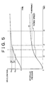
- Fig. 5 is a graph showing time-series changes in the deceleration and brake fluid pressure during brake control performed by the vehicular brake control apparatus according to the invention.
- Fig. 1 shows the structure of a vehicular brake control apparatus according to the invention.
- Fig. 2 shows the structure of a braking system of a vehicle equipped with this control apparatus.
- the vehicle has wheel cylinders 25-28 for applying a braking force to a front-right wheel FR, a front-left wheel FL, a rear-right wheel RR and a rear-left wheel RL, respectively.
- the braking of the vehicle is carried out by the wheel cylinders 25-28.
- a brake pedal 10 for operating the braking system is connected to a piston shaft of a master cylinder 11.
- a brake switch 40 for detecting an operating state of the brake pedal 10 is connected to the brake pedal 10.
- Two fluid lines including a fluid line for the front-right wheel FR and the rear-left wheel RL and a fluid line for the front-left wheel FL and the rear-right wheel RR, extend from the master cylinder 11.
- the working fluid lines are connected to the wheel cylinders 25-28 for the respective wheels through a brake actuator 50.
- the respective fluid lines branch in the brake actuator 50.
- Pressure-holding solenoid valves 15-18 and pressure-reducing solenoid valves 35-38 are disposed for the wheel cylinders 25-28 respectively.
- Pumps 12 and 13 and reservoirs 22 and 23 are disposed between the pressure-reducing solenoid valves 35, 38 and 36, 37 and branching portions, respectively.
- the output signals of wheel speed sensors 41-44 for detecting the speeds of the front wheels FR, FL and the rear wheels RR, RL and the output signal of the brake switch 40 are supplied to a brake controller 100.
- the brake controller 100 controls the solenoid valves 15-18 and 35-38 in the brake actuator 50.
- Fig. 3 is a flowchart showing the distribution control.
- Fig. 4 is a graph showing a relation between deceleration thresholds used for the distribution control and vehicle speeds.
- the piston shaft of the master cylinder 11 is pressed so that a fluid pressure (master pressure) corresponding to the brake operating amount is generated.
- master pressure a fluid pressure corresponding to the brake operating amount
- the pressure-holding solenoid valves 15-18 for the respective wheels are open, whereas the pressure-reducing solenoid valves 35-38 are shut off.
- the master pressure is introduced into the wheel cylinders 25-28 for the respective wheels, whereby the brake is operated and braking forces are applied to the respective wheels.
- step S1 the brake controller 100 monitors the vehicle speed V based on output signals of the respective wheel speed sensors 41-44, and calculates the deceleration G from a change in the vehicle speed V.
- step S2 it is judged whether or not a control for limiting the fluid pressures Pr is being performed.
- step S3 it is judged whether or not the current deceleration G has exceeded the deceleration threshold G H that is set according to the vehicle speed V as shown in Fig. 4. If the deceleration G is equal to or lower than the deceleration threshold G H (S3: No), the control is terminated without performing the braking force limiting. On the other hand, if the deceleration G has exceeded the deceleration threshold G H (S3: Yes), the operation proceeds to step S4.
- step S4 the pressure-holding solenoid valves 17, 18 connected to the wheel cylinders 27, 28 of the rear wheels RR, RL, respectively, are shut off, and the fluid pressures Pr supplied to the wheel cylinders 27, 28 are held as they are and thus prevented from increasing afterwards. Consequently, the braking forces applied to the rear wheels RR, RL are limited, the unnecessary locking of the rear wheels RR, RL is avoided, and the behavior of the vehicle is stabilized.
- the deceleration threshold G H for performing the braking force limiting is set smaller as the vehicle speed V increases. Thereby the vehicle is prevented from swaying due to the locking of the rear wheels as is often the case with a high-speed driving state, and the braking performance in the low-speed range can be guaranteed.
- the deceleration threshold G H is suitably set in accordance with the type of the vehicle, it may also be used by switching a plurality of functions in accordance with the shifting state or the like.
- the deceleration threshold G H may be set as a function of the vehicle speed V or stored in a memory in the brake controller 100 as a table in relation to the vehicle speed V.
- step S4 the deceleration at the start of the braking force limiting is incorporated into a variable Gx#M and stored in the memory in the brake controller 100.
- step S5 it is judged whether or not the current deceleration G has exceeded the value incorporated into the variable Gx#M by a predetermined value ⁇ . If Yes in step S5, the operation proceeds to step S6 where the pressure-holding solenoid valves 15, 18 connected to the wheel cylinders 27, 28 of the rear wheels RR, RL, respectively, are opened temporarily. Thereby the fluid pressures Pr supplied to the wheel cylinders 27, 28 are slightly increased pulsewise.
- the fluid pressures Pf supplied to the wheel cylinders 25, 26 for the front wheels FR, FL are not subjected to the braking force limiting. Therefore, if the brake pedal 10 has been depressed, the fluid pressures Pf increase accordingly, and the braking forces applied to the front wheels FR, FL increase so that the deceleration becomes high. In this control, if the deceleration has increased by the predetermined value ⁇ or more during the braking force limiting of the rear wheels, the braking forces applied to the rear wheels are increased slightly. Thus, if the driver has depressed the brake pedal 10 during the braking force limiting, the braking forces applied to the rear wheels can be increased accordingly.
- the driver does not feel a sense of incongruity when operating the brake.
- the stability of vehicle behavior is maintained during the braking operation, especially when the vehicle travels at a high speed.
- step S6 the deceleration at the time of changes in the braking forces for the rear wheels is substituted for the value incorporated into the variable Gx#M and stored in the memory in the brake controller 100.
- step S7 it is judged whether or not the current deceleration G has exceeded the deceleration threshold G H . If Yes in step S7, the operation is terminated without performing other processings, in order to continue the braking force limiting. If the current deceleration G is equal to or lower than the deceleration threshold G H (S7: No), the fluid pressures Pr are thereafter set in the same manner as the fluid pressures Pf by canceling the braking force limiting, that is, by opening the pressure-holding solenoid valves 17, 18. Thus, the braking forces applied to the rear wheels RR, RL are set in the same manner as those applied to the front wheels FR, FL.
- Fig. 5 is a graph showing time-series changes in the deceleration G and brake fluid pressure during brake control performed by the vehicular brake control apparatus according to the invention.
- the deceleration threshold is set to a relatively large value of G Ha as shown in Fig. 4. Therefore, the fluid pressures Pr are held as shown in Fig. 5, and the braking force limiting to the rear wheels RR, RL is performed at a time t 2 , which is after the start of the braking operation.
- the deceleration threshold is set to a relatively small value of G Hb as shown in Fig. 4. Therefore, the braking force limiting is started at the time t o , which is before the time t 2 . Because the deceleration thereafter becomes higher than the deceleration threshold G Hb at the time of the start of the control by the predetermined value a at a time t 1 , the fluid pressures Pr are then increased pulsewise. Furthermore, because the deceleration becomes higher than the deceleration threshold G Hb at a time t 3 , by 2 ⁇ , the fluid pressures Pr are again increased pulsewise.
- the fluid pressures Pr applied to the side of the rear wheels are changed along the passage of time pulsewise, that is, stepwise.
- the fluid pressures Pr may be changed smoothly by means of the brake controller 100 to prevent the driver and any passengers from feeling a sense of incongruity.
- the brake operating amount by the driver is determined based on changes in the deceleration.
- the increase in the brake operating amount may be determined by detecting an increase in the brake stroke or master pressure.
- the brake control for the rear wheels may be performed by detecting an increase in the slip amounts of the rear wheels based on the output values of the respective wheel speed sensors.
- the brake controller 100 can be implemented using a single special purpose integrated circuit (e.g., ASIC) having a main or central processor section for overall, system-level control, and separate sections dedicated to performing various different specific computations, functions and other processes under control of the PLC.
- the brake controller 100 also can be a plurality of separate dedicated or programmable integrated or other electronic circuits or devices (e.g., hardwired electronic or logic circuits such as discrete element circuits, or programmable logic devices such as PLDs, PLAs, PALs or the like).
- the brake controller 100 can be implemented using a suitably programmed general purpose computer, e.g., a microprocessor, microcontroller or other processor device (CPU or MPU), either alone or in conjunction with one or more peripheral (e.g., integrated circuit) data and signal processing devices.
- a suitably programmed general purpose computer e.g., a microprocessor, microcontroller or other processor device (CPU or MPU), either alone or in conjunction with one or more peripheral (e.g., integrated circuit) data and signal processing devices.
- CPU or MPU processor device
- peripheral e.g., integrated circuit
- a distributed processing architecture can be used for maximum data/signal processing capability and speed.
Landscapes
- Engineering & Computer Science (AREA)
- Transportation (AREA)
- Mechanical Engineering (AREA)
- Hydraulic Control Valves For Brake Systems (AREA)
- Regulating Braking Force (AREA)
Abstract
Description
Claims (8)
- A vehicular brake control apparatus, characterized by comprising:a brake controller (100) that:determines a brake operating amount by a driver;limits braking forces applied to rear wheels of the vehicle in comparison with braking forces applied to front wheels when the vehicle is in a predetermined driving state; andincreases the braking forces applied to the rear wheels, if the brake controller determines, during the braking force limiting, that the brake operating amount has increased.
- The apparatus according to claim 1, characterized in that
the brake controller (100) determines that the vehicle is in the predetermined driving state when the deceleration of the vehicle is equal to or higher than a threshold value, and performs the braking force limiting. - The apparatus according to claim 1 or 2, characterized in that
the brake controller (100) determines that the brake operating amount by the driver has increased by determining that the deceleration of the vehicle has increased. - The apparatus according to any one of claims 1 to 3, characterized in that the brake controller (100) determines that the brake operating amount by the driver has increased by detecting an increase in a stroke of a brake pedal (10).
- The apparatus according to any one of claims 1 to 4, characterized in that the brake controller (100) determines that the brake operating amount by the driver has increased by detecting an increase in pressure in a master cylinder (11).
- The apparatus according to any one of claims 1 to 5, characterized in that the brake controller (100) determines that the brake operating amount by the driver has increased during braking force limiting by determining that a deceleration at the start of the braking force limiting has increased by more than a predetermined value.
- The apparatus according to claim 6, characterized in thatthe brake controller (100) determines if the deceleration is equal to or lower than a threshold value when the deceleration at the start of the braking force limiting has not increased by more than the predetermined value; andcancels the braking force limiting when the deceleration is equal to or lower than the threshold value.
- A vehicular brake control method, characterized by comprising:determining a brake operating amount by a driver;:limiting braking forces applied to rear wheels of the vehicle in comparison with braking forces applied to front wheels when the vehicle is in a predetermined driving state; andincreasing the braking forces applied to the rear wheels, if it is determined, during the braking force limiting, that the brake operating amount has increased.
Applications Claiming Priority (2)
| Application Number | Priority Date | Filing Date | Title |
|---|---|---|---|
| JP2000035157 | 2000-02-14 | ||
| JP2000035157A JP3870652B2 (en) | 2000-02-14 | 2000-02-14 | Brake control device for vehicle |
Publications (3)
| Publication Number | Publication Date |
|---|---|
| EP1125809A2 true EP1125809A2 (en) | 2001-08-22 |
| EP1125809A3 EP1125809A3 (en) | 2003-05-14 |
| EP1125809B1 EP1125809B1 (en) | 2006-08-30 |
Family
ID=18559398
Family Applications (1)
| Application Number | Title | Priority Date | Filing Date |
|---|---|---|---|
| EP01103373A Expired - Lifetime EP1125809B1 (en) | 2000-02-14 | 2001-02-13 | Vehicular brake control apparatus and vehicular brake control method |
Country Status (6)
| Country | Link |
|---|---|
| US (1) | US6443540B2 (en) |
| EP (1) | EP1125809B1 (en) |
| JP (1) | JP3870652B2 (en) |
| KR (1) | KR100434209B1 (en) |
| CN (1) | CN1187213C (en) |
| DE (1) | DE60122605T2 (en) |
Cited By (3)
| Publication number | Priority date | Publication date | Assignee | Title |
|---|---|---|---|---|
| EP1388475A1 (en) * | 2002-08-06 | 2004-02-11 | Renault s.a.s. | Vehicle braking control method, braking force distribution control system and vehicle equipped with such a system |
| EP1621431A1 (en) * | 2004-07-26 | 2006-02-01 | Delphi Technologies, Inc. | Method and system for front/rear brake force distribution for a motor vehicle |
| CN100418818C (en) * | 2005-03-04 | 2008-09-17 | 本田技研工业株式会社 | brake control device |
Families Citing this family (18)
| Publication number | Priority date | Publication date | Assignee | Title |
|---|---|---|---|---|
| KR100721388B1 (en) * | 2002-07-11 | 2007-05-23 | 주식회사 만도 | Control Method of Electro-Hydraulic Braking System |
| JP2004306785A (en) | 2003-04-07 | 2004-11-04 | Toyota Motor Corp | Vehicle braking control device |
| JP4099096B2 (en) | 2003-04-07 | 2008-06-11 | トヨタ自動車株式会社 | Brake control device for vehicle |
| JP4554166B2 (en) | 2003-04-07 | 2010-09-29 | トヨタ自動車株式会社 | Brake control device for vehicle |
| US7020551B2 (en) * | 2003-12-23 | 2006-03-28 | Bendix Commercial Vehicle Systems Llc | Roll stability control system |
| CA2528903C (en) * | 2004-12-20 | 2008-01-15 | Honda Motor Co., Ltd. | Braking device for motorcycle |
| US7809486B2 (en) * | 2005-04-29 | 2010-10-05 | Kelsey-Hayes Company | Pressure boost for vehicle rear brake circuits |
| CN100486843C (en) * | 2006-05-17 | 2009-05-13 | 比亚迪股份有限公司 | Method for building and controlling brake force in motor automobile |
| JP5217834B2 (en) * | 2008-09-22 | 2013-06-19 | トヨタ自動車株式会社 | Traction drive vehicle with different braking assistance when towing and when not towing |
| US8738248B2 (en) * | 2008-10-21 | 2014-05-27 | Allison Transmission, Inc. | System for controlling vehicle overspeeding via control of one or more exhaust brake devices |
| JP2010247730A (en) * | 2009-04-17 | 2010-11-04 | Toyota Motor Corp | Vehicle control device |
| JP5131498B2 (en) * | 2010-11-25 | 2013-01-30 | トヨタ自動車株式会社 | Braking force control device for vehicle |
| JP5196203B2 (en) * | 2010-11-30 | 2013-05-15 | トヨタ自動車株式会社 | Braking force control device for vehicle |
| EP3082417B1 (en) * | 2013-12-19 | 2019-08-14 | Dow Global Technologies LLC | Additive package compositions for pesticide suspension concentrate formulations |
| JP6520874B2 (en) * | 2016-09-12 | 2019-05-29 | トヨタ自動車株式会社 | Vehicle control device |
| JP2019051810A (en) * | 2017-09-14 | 2019-04-04 | 日立オートモティブシステムズ株式会社 | Vehicle brake control device, vehicle brake control method and vehicle brake system |
| JP7522075B2 (en) * | 2021-05-27 | 2024-07-24 | 日立Astemo株式会社 | Brake control device and brake control method |
| CN117480079A (en) * | 2021-06-18 | 2024-01-30 | 沃尔沃卡车集团 | Method for evaluating the reliability of a vehicle brake assembly |
Family Cites Families (22)
| Publication number | Priority date | Publication date | Assignee | Title |
|---|---|---|---|---|
| JPH0585327A (en) * | 1991-09-25 | 1993-04-06 | Aisin Seiki Co Ltd | Anti-skid device |
| JPH05213169A (en) | 1992-02-04 | 1993-08-24 | Rhythm Corp | Hydraulic control device of brake |
| DE4326256C1 (en) * | 1993-08-05 | 1994-12-01 | Daimler Benz Ag | Method for determining a wear-dependent braking force distribution |
| DE4417935A1 (en) * | 1994-05-21 | 1995-11-23 | Teves Gmbh Alfred | Circuit arrangement for a brake system with electronic control of the brake force distribution |
| DE4424317C2 (en) * | 1994-07-09 | 2003-11-13 | Bosch Gmbh Robert | Anti-lock control system |
| JP3346041B2 (en) * | 1994-07-20 | 2002-11-18 | アイシン精機株式会社 | Anti-skid control device |
| US5620240A (en) * | 1994-09-09 | 1997-04-15 | Kelsey-Hayes Company | Anti-lock brake method and system including a variable primary to secondary apply hold stage |
| DE19510746A1 (en) * | 1995-03-24 | 1996-09-26 | Bosch Gmbh Robert | Method and device for controlling the brake system of a vehicle |
| US5646849A (en) * | 1995-08-09 | 1997-07-08 | General Motors Corporation | Method for proportionally controlling the brakes of a vehicle based on front and rear wheel speeds |
| US5632535A (en) * | 1995-08-28 | 1997-05-27 | Kelsey-Hayes Company | Dynamic rear proportioning brake system |
| JP3132371B2 (en) * | 1995-10-06 | 2001-02-05 | トヨタ自動車株式会社 | Vehicle behavior control device |
| DE19541601B4 (en) * | 1995-11-08 | 2007-08-09 | Robert Bosch Gmbh | Method and device for controlling the brake system of a vehicle |
| JP3497304B2 (en) * | 1995-11-17 | 2004-02-16 | 本田技研工業株式会社 | Vehicle braking force control device |
| JP3257392B2 (en) * | 1996-02-23 | 2002-02-18 | トヨタ自動車株式会社 | Vehicle behavior control device |
| JP3456835B2 (en) | 1996-06-10 | 2003-10-14 | 日信工業株式会社 | Anti-lock brake control device for vehicle |
| JPH1035461A (en) | 1996-07-19 | 1998-02-10 | Nisshinbo Ind Inc | Cascade lock tendency detecting method and anti-lock brake controlling method |
| JP3473659B2 (en) * | 1996-09-09 | 2003-12-08 | トヨタ自動車株式会社 | Braking force distribution control device |
| DE19812554A1 (en) * | 1997-11-06 | 1999-05-12 | Itt Mfg Enterprises Inc | Method for controlling the brake pressure curve in the rear wheel brakes for a vehicle brake system with EBV |
| JP4440459B2 (en) | 1997-11-20 | 2010-03-24 | コンティネンタル・テーベス・アクチエンゲゼルシヤフト・ウント・コンパニー・オッフェネ・ハンデルスゲゼルシヤフト | Method and apparatus for controlling or adjusting braking force distribution |
| US6079800A (en) * | 1998-08-20 | 2000-06-27 | General Motors Corporation | Active brake control with front-to-rear proportioning |
| US6241326B1 (en) * | 1998-10-28 | 2001-06-05 | Kelsey-Hayes Company | Electronic brake proportioning for a rear wheel anti-lock brake system |
| JP2000168534A (en) * | 1998-12-08 | 2000-06-20 | Nisshinbo Ind Inc | Braking force distribution control method |
-
2000
- 2000-02-14 JP JP2000035157A patent/JP3870652B2/en not_active Expired - Fee Related
-
2001
- 2001-01-19 US US09/764,155 patent/US6443540B2/en not_active Expired - Fee Related
- 2001-02-08 KR KR10-2001-0006107A patent/KR100434209B1/en not_active Expired - Fee Related
- 2001-02-13 DE DE60122605T patent/DE60122605T2/en not_active Expired - Lifetime
- 2001-02-13 EP EP01103373A patent/EP1125809B1/en not_active Expired - Lifetime
- 2001-02-14 CN CNB011045094A patent/CN1187213C/en not_active Expired - Fee Related
Cited By (4)
| Publication number | Priority date | Publication date | Assignee | Title |
|---|---|---|---|---|
| EP1388475A1 (en) * | 2002-08-06 | 2004-02-11 | Renault s.a.s. | Vehicle braking control method, braking force distribution control system and vehicle equipped with such a system |
| FR2843350A1 (en) * | 2002-08-06 | 2004-02-13 | Renault Sa | METHOD FOR CONTROLLING THE BRAKING OF THE WHEELS OF A MOTOR VEHICLE, DEVICE FOR CONTROLLING THE DISTRIBUTION OF BRAKING EFFORTS AND VEHICLE PROVIDED WITH SUCH A DEVICE |
| EP1621431A1 (en) * | 2004-07-26 | 2006-02-01 | Delphi Technologies, Inc. | Method and system for front/rear brake force distribution for a motor vehicle |
| CN100418818C (en) * | 2005-03-04 | 2008-09-17 | 本田技研工业株式会社 | brake control device |
Also Published As
| Publication number | Publication date |
|---|---|
| JP3870652B2 (en) | 2007-01-24 |
| US6443540B2 (en) | 2002-09-03 |
| KR20010082070A (en) | 2001-08-29 |
| EP1125809B1 (en) | 2006-08-30 |
| DE60122605T2 (en) | 2007-08-30 |
| CN1309044A (en) | 2001-08-22 |
| US20010013724A1 (en) | 2001-08-16 |
| CN1187213C (en) | 2005-02-02 |
| JP2001219834A (en) | 2001-08-14 |
| EP1125809A3 (en) | 2003-05-14 |
| KR100434209B1 (en) | 2004-06-04 |
| DE60122605D1 (en) | 2006-10-12 |
Similar Documents
| Publication | Publication Date | Title |
|---|---|---|
| EP1125809B1 (en) | Vehicular brake control apparatus and vehicular brake control method | |
| US4881785A (en) | Anti-lock brake control method and system for motor vehicles | |
| US6089682A (en) | Antilock brake control system for vehicle | |
| JPH10509111A (en) | Circuit device for anti-lock control type brake device | |
| US6491358B2 (en) | Braking force control system for vehicle | |
| JPH04218453A (en) | Braking liquid pressure controller for vehicle | |
| US6582034B2 (en) | Vehicular brake control method and apparatus | |
| US6126250A (en) | Braking system for a motor vehicle | |
| JP3034453B2 (en) | Anti-lock brake control device | |
| US6470255B2 (en) | Vehicular braking control apparatus and control method thereof | |
| US12049214B2 (en) | Braking control apparatus | |
| US6789858B2 (en) | Braking force control system for vehicle | |
| US6246946B1 (en) | Automotive brake control system with skid control unit | |
| US6443541B1 (en) | Braking control apparatus and method for vehicles | |
| US6116705A (en) | Anti-skid control system | |
| JP4858110B2 (en) | Vehicle braking force control device | |
| JP3329181B2 (en) | Geared vibration determination device and braking force control device using the same | |
| JPH0789426A (en) | Braking force distribution control device | |
| JP2000127936A (en) | Anti-lock brake control method for vehicle | |
| KR0154054B1 (en) | Idle up control device and method of abs system | |
| JP2001315631A (en) | Vehicle brake control device | |
| JP2024173005A (en) | Vehicle brake control device | |
| KR100751258B1 (en) | How to determine road surface change during braking | |
| JPH04342649A (en) | anti-skid control device | |
| JP5133555B2 (en) | Vehicle braking force control device |
Legal Events
| Date | Code | Title | Description |
|---|---|---|---|
| PUAI | Public reference made under article 153(3) epc to a published international application that has entered the european phase |
Free format text: ORIGINAL CODE: 0009012 |
|
| 17P | Request for examination filed |
Effective date: 20010307 |
|
| AK | Designated contracting states |
Kind code of ref document: A2 Designated state(s): AT BE CH CY DE DK ES FI FR GB GR IE IT LI LU MC NL PT SE TR |
|
| AX | Request for extension of the european patent |
Free format text: AL;LT;LV;MK;RO;SI |
|
| PUAL | Search report despatched |
Free format text: ORIGINAL CODE: 0009013 |
|
| AK | Designated contracting states |
Designated state(s): AT BE CH CY DE DK ES FI FR GB GR IE IT LI LU MC NL PT SE TR |
|
| AX | Request for extension of the european patent |
Extension state: AL LT LV MK RO SI |
|
| RIC1 | Information provided on ipc code assigned before grant |
Ipc: 7B 60T 8/00 B Ipc: 7B 60T 8/26 A |
|
| AKX | Designation fees paid |
Designated state(s): DE FR GB |
|
| 17Q | First examination report despatched |
Effective date: 20050704 |
|
| GRAP | Despatch of communication of intention to grant a patent |
Free format text: ORIGINAL CODE: EPIDOSNIGR1 |
|
| GRAS | Grant fee paid |
Free format text: ORIGINAL CODE: EPIDOSNIGR3 |
|
| RIN1 | Information on inventor provided before grant (corrected) |
Inventor name: SHIMIZU, SATOSHI Inventor name: TSUCHIYA, YOSHIAKI |
|
| RAP1 | Party data changed (applicant data changed or rights of an application transferred) |
Owner name: TOYOTA JIDOSHA KABUSHIKI KAISHA |
|
| GRAA | (expected) grant |
Free format text: ORIGINAL CODE: 0009210 |
|
| AK | Designated contracting states |
Kind code of ref document: B1 Designated state(s): DE FR GB |
|
| REG | Reference to a national code |
Ref country code: GB Ref legal event code: FG4D |
|
| REF | Corresponds to: |
Ref document number: 60122605 Country of ref document: DE Date of ref document: 20061012 Kind code of ref document: P |
|
| ET | Fr: translation filed | ||
| PLBE | No opposition filed within time limit |
Free format text: ORIGINAL CODE: 0009261 |
|
| STAA | Information on the status of an ep patent application or granted ep patent |
Free format text: STATUS: NO OPPOSITION FILED WITHIN TIME LIMIT |
|
| 26N | No opposition filed |
Effective date: 20070531 |
|
| REG | Reference to a national code |
Ref country code: GB Ref legal event code: 746 Effective date: 20090616 |
|
| PGFP | Annual fee paid to national office [announced via postgrant information from national office to epo] |
Ref country code: FR Payment date: 20120221 Year of fee payment: 12 |
|
| PGFP | Annual fee paid to national office [announced via postgrant information from national office to epo] |
Ref country code: DE Payment date: 20120208 Year of fee payment: 12 |
|
| PGFP | Annual fee paid to national office [announced via postgrant information from national office to epo] |
Ref country code: GB Payment date: 20120208 Year of fee payment: 12 |
|
| GBPC | Gb: european patent ceased through non-payment of renewal fee |
Effective date: 20130213 |
|
| REG | Reference to a national code |
Ref country code: FR Ref legal event code: ST Effective date: 20131031 |
|
| REG | Reference to a national code |
Ref country code: DE Ref legal event code: R119 Ref document number: 60122605 Country of ref document: DE Effective date: 20130903 |
|
| PG25 | Lapsed in a contracting state [announced via postgrant information from national office to epo] |
Ref country code: DE Free format text: LAPSE BECAUSE OF NON-PAYMENT OF DUE FEES Effective date: 20130903 Ref country code: GB Free format text: LAPSE BECAUSE OF NON-PAYMENT OF DUE FEES Effective date: 20130213 Ref country code: FR Free format text: LAPSE BECAUSE OF NON-PAYMENT OF DUE FEES Effective date: 20130228 |