EP1125802A2 - Buckle Device - Google Patents
Buckle Device Download PDFInfo
- Publication number
- EP1125802A2 EP1125802A2 EP01301414A EP01301414A EP1125802A2 EP 1125802 A2 EP1125802 A2 EP 1125802A2 EP 01301414 A EP01301414 A EP 01301414A EP 01301414 A EP01301414 A EP 01301414A EP 1125802 A2 EP1125802 A2 EP 1125802A2
- Authority
- EP
- European Patent Office
- Prior art keywords
- tongue plate
- latch
- sensor
- buckle device
- buckle
- Prior art date
- Legal status (The legal status is an assumption and is not a legal conclusion. Google has not performed a legal analysis and makes no representation as to the accuracy of the status listed.)
- Granted
Links
Images


Classifications
-
- B—PERFORMING OPERATIONS; TRANSPORTING
- B60—VEHICLES IN GENERAL
- B60R—VEHICLES, VEHICLE FITTINGS, OR VEHICLE PARTS, NOT OTHERWISE PROVIDED FOR
- B60R22/00—Safety belts or body harnesses in vehicles
- B60R22/48—Control systems, alarms, or interlock systems, for the correct application of the belt or harness
- B60R2022/4808—Sensing means arrangements therefor
- B60R2022/4816—Sensing means arrangements therefor for sensing locking of buckle
-
- Y—GENERAL TAGGING OF NEW TECHNOLOGICAL DEVELOPMENTS; GENERAL TAGGING OF CROSS-SECTIONAL TECHNOLOGIES SPANNING OVER SEVERAL SECTIONS OF THE IPC; TECHNICAL SUBJECTS COVERED BY FORMER USPC CROSS-REFERENCE ART COLLECTIONS [XRACs] AND DIGESTS
- Y10—TECHNICAL SUBJECTS COVERED BY FORMER USPC
- Y10T—TECHNICAL SUBJECTS COVERED BY FORMER US CLASSIFICATION
- Y10T24/00—Buckles, buttons, clasps, etc.
- Y10T24/45—Separable-fastener or required component thereof [e.g., projection and cavity to complete interlock]
- Y10T24/45225—Separable-fastener or required component thereof [e.g., projection and cavity to complete interlock] including member having distinct formations and mating member selectively interlocking therewith
- Y10T24/45602—Receiving member includes either movable connection between interlocking components or variable configuration cavity
- Y10T24/45623—Receiving member includes either movable connection between interlocking components or variable configuration cavity and operator therefor
- Y10T24/45639—Receiving member includes either movable connection between interlocking components or variable configuration cavity and operator therefor including pivotally connected element on receiving member
-
- Y—GENERAL TAGGING OF NEW TECHNOLOGICAL DEVELOPMENTS; GENERAL TAGGING OF CROSS-SECTIONAL TECHNOLOGIES SPANNING OVER SEVERAL SECTIONS OF THE IPC; TECHNICAL SUBJECTS COVERED BY FORMER USPC CROSS-REFERENCE ART COLLECTIONS [XRACs] AND DIGESTS
- Y10—TECHNICAL SUBJECTS COVERED BY FORMER USPC
- Y10T—TECHNICAL SUBJECTS COVERED BY FORMER US CLASSIFICATION
- Y10T24/00—Buckles, buttons, clasps, etc.
- Y10T24/45—Separable-fastener or required component thereof [e.g., projection and cavity to complete interlock]
- Y10T24/45225—Separable-fastener or required component thereof [e.g., projection and cavity to complete interlock] including member having distinct formations and mating member selectively interlocking therewith
- Y10T24/45602—Receiving member includes either movable connection between interlocking components or variable configuration cavity
- Y10T24/45623—Receiving member includes either movable connection between interlocking components or variable configuration cavity and operator therefor
- Y10T24/4566—Receiving member includes either movable connection between interlocking components or variable configuration cavity and operator therefor including slidably connected and guided element on receiving member
- Y10T24/4567—Receiving member includes either movable connection between interlocking components or variable configuration cavity and operator therefor including slidably connected and guided element on receiving member for shifting slidably connected and guided, nonself-biasing, interlocking component
Abstract
Description
- The present invention relates to a buckle device, which, in a seat belt device for a vehicle, maintains a state in which a webbing belt restrains the body of a vehicle occupant.
- A buckle device forms a portion of a seat belt device for restraining, by an elongated webbing belt, the body of a vehicle occupant who is seated in a seat of a vehicle. The buckle device is locked by passing a latch through a hole formed in a tongue plate provided at the webbing belt in a state in which the tongue plate is inserted into a case of the buckle device, so as to apply the webbing belt to the vehicle occupant.
Among such buckle devices, there are those of the type which are provided with a detecting means for detecting whether the latch is engaged with the tongue plate. The detecting means detects unlocked states, such as the tongue plate not being completely inserted into the case or the latch not being
engaged even if the tongue plate is completely inserted. Notice can be given of the locked state by, for example, having an indicator be lit only at times when the buckle device is in a locked state.
One example of such a detecting means is a structure using a so-called Hall sensor. (For an example of a structure using a Hall sensor, refer to Japanese Patent Application Laid-Open (JP-A) No. 10-230815, whose counterpart US patent is USP No. 5,742,986.) The Hall sensor is an electronic part whose electrical resistance value varies in accordance with the intensity of a magnetic field by application of the so-called Hall effect.
In such a detecting means utilizing a Hall sensor, for example, the Hall sensor is disposed so as to oppose the latch along the moving direction of the latch within the buckle body, and a magnet (a permanent magnet)is disposed at the side of the Hall sensor which is opposite the side at which the latch is provided. The latch is formed of a magnetic body of iron or the like. The Hall sensor detects changes in the intensity of the magnetic field of the magnet with respect to the Hall sensor, which changes are caused by the latch approaching or moving away from the Hall sensor and the magnet when the latch is engaged with the tongue plate and locked or when this locking is released. Due to the Hall sensor detecting such changes, it can be detected whether or not the latch is engaged with the tongue plate and locked.
However, buckle devices, in which whether or not the tongue plate is locked is detected by using a Hall sensor, have the following problems.
First, as described above, the Hall sensor is of a structure in which the intensity of a magnetic field is fed out as an electric signal by using the Hall effect. Accordingly, when the magnetic force of the magnet, which is the source of the magnetic field, deteriorates due to the passage of time or the like, there is the possibility that, regardless of whether the latch has approached the Hall sensor, the Hall sensor can only detect a magnetic field of an intensity which is the same as that if the latch had not approached the Hall sensor. Thus, a structure utilizing a Hall sensor lacks reliability for use in a buckle device which is used over a relatively long period of time.
Second, Hall sensors generally have poor temperature characteristics. They thus lack reliability for use in buckle devices which are provided in vehicles in which temperature variations are great. - In view of the aforementioned, an object of the present invention is to provide a buckle device in which it can be detected whether or not a tongue plate inserted into a case is locked, and in which the reliability of such detection is high.
- In order to solve the above-described problems, a buckle device of the present invention comprises: a tongue plate; a buckle main body; a movable latch interlocking with the tongue plate which is inserted into the buckle main body; at least one movable magnetic body related to interlock operation; and a sensor operable for detecting movement of the magnetic body, wherein the sensor includes a magnetoresistance element utilizing an anisotropic magnetoresistance effect, and a bias magnet.
- A belt buckle device of the present invention comprises: a belt having a tongue plate at one end of the belt; a buckle main body; a latch which releasably interlocks with the tongue plate within the buckle main body; and a sensor for detecting interlock operation, the sensor including a magnetoresistance element utilizing an anisotropic magnetoresistance effect, and a bias magnet.
- A seat belt device for a vehicle of the present invention comprises: a flexible belt, one end of the flexible belt being mounted one of directly and indirectly to one of a vehicle body and a seat, the other end of the flexible belt having a tongue plate; a buckle main body, one end of the buckle main body being mounted one of directly and indirectly to one of the vehicle body and the seat, the other end of the buckle main body having an opening; a movable latch for interlocking with a tongue plate which is inserted into the opening of the buckle main body; and a sensor operable for detecting interlocking operation, the sensor including a magnetoresistance element utilizing an anisotropic magnetoresistance effect, and a bias magnet.
- Fig. 1 is a cross-sectional view illustrating the structure of a buckle device relating to a first embodiment of the present invention.
- Fig. 2 is an exploded perspective view illustrating the structure of the buckle device relating to the first embodiment of the present invention.
- Fig. 3 is a drawing which schematically illustrates the positional relationships between a magnetoresistance sensor, a magnet and a magnetic body.
- Fig. 4 is a graph showing electric potential differences at respective positions of the magnetic body.
- Fig. 5 is a cross-sectional view illustrating the structure of a buckle device relating to a second embodiment of the present invention.
- Figs. 6A through 6E are drawings which schematically illustrate the positional relationships between a magnetoresistance sensor, a magnet, a tongue plate, and a latch.
- Fig. 7 is a graph showing electric potential differences at respective positions of a magnetic body.
- Fig. 8 is a drawing which schematically illustrates a modified example in which the positional relationship of the magnet and the magnetoresistance sensor is changed.
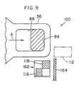
- Fig. 9 is a schematic plan view illustrating the structure of a buckle device relating to a third embodiment of the present invention.
- Fig. 2 is an exploded perspective view of a
buckle device 10 relating to a first embodiment of the present invention. Fig. 1 is a cross-sectional view of thebuckle device 10 in an appropriate position. As illustrated in these drawings, thebuckle device 10 is provided with a substantially box-shaped case 12. Thecase 12 is formed from a synthetic resin material. Anelongated slit hole 14 is formed along the transverse direction of thecase 12 at one longitudinal direction end portion of thecase 12. Anopening 16 is formed in the other longitudinal direction end portion of thecase 12.
A bucklemain body 20 is accommodated in thecase 12. The bucklemain body 20 is provided with ananchor plate 26 serving as a guide and mounted byrivets 24 to amounting portion 22 which extends from a vehicle body (not shown). Theanchor plate 26 is formed as an elongated plate which has been folded over at the longitudinal direction central portion thereof, such that an
upper plate 28 and alower plate 30, which are disposed parallel to each other with a predetermined interval therebetween, are formed at theanchor plate 26. Aninsertion hole 32 is formed in the center of one end (the folded-over portion) of theanchor plate 26. Atongue plate 36 is inserted, from thisinsertion hole 32, into aninsertion portion 34 which is formed between theupper plate 28 and thelower plate 30. A through hole (not shown) is formed in thetongue plate 36. The webbing of a seat belt device is inserted through this through hole. Further, themounting portion 22 is inserted and fixed from the other end side of theanchor plate 26.
Anejector 38 is accommodated within theanchor plate 26 so as to be slidable along the longitudinal direction of the anchor plate 26 (i.e., in the direction of arrow A in Figs. 1 and 2 and the direction opposite thereto). Anejector spring 40 is disposed between theejector 38 and themounting portion 22, and urges theejector 38 toward the insertion hole 32 (i.e., in the direction opposite to the direction of arrow A in Figs. 1 and 2).
A pair ofcorner portions 42, which are directed toward themounting plate 22, project out from both transverse direction ends of theejector 38.Projections 44 formed substantially at the longitudinal direction centers of thecorner portions 42 are formed at predetermined positions such that, when theejector 38 is pushed by thetongue plate 36 and moves toward themounting portion 22, theprojections 44 press against projections (not shown) which are formed to project from abutton 50. Further, sliding of theejector 38 is limited to a fixed range by abuttingportions 46, which are formed in vicinities of the distal ends of thecorner portions 42, abutting projections (not shown) which project from theanchor plate 26 into theinsertion portion 34.
Thebutton 50 is mounted to theupper plate 28 of theanchor plate 26. Thebutton 50 is formed in a substantially rectangular frame shape as viewed from above. Thebutton 50 has anoperation portion 52 for push operation, a pair of parallelouter plates 54 which project from vicinities of transverse direction end portions of theoperation portion 52, and a pair of parallelinner plates 58 which project from a region of thebutton 50 further toward the transverse direction inner side thereof than theouter plates 54.
Aclaw 62 is formed at the projecting end of eachouter plate 54 and is directed inwardly. Theclaw 62 engages from the outer side of theanchor plate 26 with the region between theupper plate 28 and thelower plate 30 of theanchor plate 26, such that thebutton 50 cannot be separated from theanchor plate 26. Further, theclaw 62 is slidable along the longitudinal direction of the anchor plate 26 (in the direction of arrow A in Figs. 1 and 2 and the direction opposite thereto).
Aprojection 64 is formed at the inner side of theinner plate 58. Aninclined surface 66 is formed further toward theoperation portion 52 side than theprojection 64 is. Theinclined surface 66 slants in the direction of gradually moving away from theanchor plate 26, along the direction toward theoperation portion 52. In a state in which thetongue plate 36 is not inserted into theinsertion portion 34, theprotrusions 64 abut alatch 84, which serves as a lock member and which will be described later, so as to prevent movement of thelatch 84 in an engaging direction (the direction of arrow B in Figs. 1 and 2). Further, in the state in which thetongue plate 36 is inserted into theinsertion portion 34 and thelatch 84 is engaged with an engagement
hole 88 of the tongue plate 36 (i.e., in the locked state), theprotrusions 64 abut upper surfaces ofabutment portions 86 of thelatch 84, such that movement of thelatch 84 in the engagement releasing direction (the direction opposite to the direction of arrow B in Figs. 1 and 2) is prevented.
In the locked state, when thebutton 50 is moved in the lock releasing direction (the direction of arrow A in Figs. 1 and 2), theinclined surfaces 66 convert this pressing force into force for moving thelatch 84 in the engagement releasing direction (the direction opposite to the direction of arrow B in Figs. 1 and 2), and press theabutment portions 86 from the lower surfaces thereof. In this way, thelatch 84 is moved in the engagement releasing direction.
A holdingblock 80, which straddles over theinner plates 58, is formed to stand from at theupper plate 28 at a position which is further inward than theouter plates 54 of thebutton 50. The holdingblock 80 has a pair ofparallel holding plates 82. Thelatch 84 is disposed between the holdingplates 82. The holdingplates 82 prevent movement of thelatch 84 in the longitudinal direction of the anchor plate 26 (in the direction of arrow A in Figs. 1 and 2 and the direction opposite thereto), and allow thelatch 84 to move in the engaging direction and the engagement releasing direction (the direction of arrow B in Figs. 1 and 2 and the direction opposite thereto).
Thelatch 84 is formed in a substantial U-shape as seen from the front. Theabutment portions 86 project toward the transverse direction outer sides from the upper surface of thelatch 84. Anengagement portion 90 projects toward thetongue plate 36 from the transverse direction center of thelatch 84. When thetongue plate 36 is inserted in theinsertion portion 34 to a predetermined position, theengagement portion 90 passes through a throughhole 92 formed in theupper plate 28 of theanchor plate 26, and engages with theengagement hole 88 of theanchor plate 26, and passes through a through hole 94 (see Fig. 1) formed in thelower plate 30.
A pair ofplate spring portions 96 are formed to project from the holdingblock 80 toward theoperation portion 52 of thebutton 50. Theplate spring portions 96 urge thebutton 50 in the direction opposite to the direction of arrow A in Figs. 1 and 2. In this way, an appropriate resistance is generated at the time when theoperation button 52 is pushed.
A middle plate 76, in which an opening is appropriately formed, is provided between theouter plates 52 of thebutton 50. Aleg portion 68 is formed so as to project downwardly from the middle plate 76. Theleg portion 68 passes through anelongated hole 70 formed in theupper plate 28, and is positioned between theupper plate 28 and thelower plate 30. The longitudinal direction of theelongated hole 70 runs along the sliding direction of thebutton 50. Due to thebutton 50 being slid, theleg portion 68 moves along theelongated hole 70. Further, due to theleg portion 68 being moved along theelongated hole 70, thebutton 50 is slid. Theleg portion 68 which has passed through theelongated hole 70 is positioned on the locus of movement of thetongue plate 36 which moves between theupper plate 28 and thelower plate 30. When thetongue plate 36 reaches a predetermined position between theupper plate 28 and thelower plate 30, thetongue plate 36 abuts theleg portion 68. In this state, when thetongue plate 36 is further slid, theleg portion 68 is pressed by thetongue plate 36 and moves.
Amagnetic plate 72, which serves as a magnetic body and is formed of iron or the like, is adhered and fixed to the end surface of theleg portion 68 at the side opposite the side facing thetongue plate 36 which is positioned between theupper plate 28 and thelower plate 30.
One end of a plate-spring-shapedlock spring 98 is mounted to thebutton 50. The other end of thelock spring 98 abuts the upper surface of thelatch 84 and urges thelatch 84 in the engaging direction (the direction of arrow B in Figs. 1 and 2).
Thepresent buckle device 10 is provided with asensing portion 112 which forms alock detecting device 110. Thesensing portion 112 has amagnet 116. Themagnet 116 is disposed at the side of theleg portion 68 which is opposite the side at which thetongue plate 36, positioned between theupper plate 28 and thelower plate 30, is located. Themagnet 116 has polarity along the direction in which thetongue plate 36 slides between theupper plate 28 and thelower plate 30. (Specifically, the N pole of themagnet 116 is positioned at theleg portion 68 side, and the S pole is positioned at the opposite side.) An MRE sensor (magnetoresistance sensor) 118 is disposed adjacent to themagnet 116 at theleg portion 68 side of themagnet 116. TheMRE sensor 118 may be formed by a so-called "strong magnetic body magnetoresistance element" which is formed by a strong magnetic body of a nickel-cobalt (Ni-Co) alloy whose main components are nickel and cobalt, or the like. Or, theMRE sensor 118 may be formed by a so-called "semiconductor magnetoresistance element" formed from indium antimonide, or the like. TheMRE sensor 118 is a type of variable resistance element which varies the electrical resistance value in accordance with the orientation of the magnetic field crossing theMRE sensor 118.
The electrical circuit including thesensing portion 112 is electrically connected to a control device (not shown) such as a computer or the like. This electrical circuit is electrically connected, via the control device, to a lamp (not shown) provided at the instrument panel or the like of the vehicle. The control device fetches the electric potential difference which varies in accordance with changes in the electrical resistance value of theMRE sensor 118 detected by a detector provided at the aforementioned electrical circuit. If the fetched electric potential difference is the same as or is within a range which is judged to be the same as a predetermined electric potential difference stored in advance in the control device, the lamp is lit.
Next, operation and effects of the present embodiment will be described.
In a state in which thetongue plate 36 is not inserted in theinsertion portion 34, theprojections 64 of thebutton 50 abut theabutment portions 86 of thelatch 84 from the lower sides thereof. Movement of thelatch 84 in the engaging direction (in the direction of arrow B in Figs. 1 and 2) due to the urging force of thelock spring 98 is prevented.
When thetongue plate 36 is inserted in theinsertion portion 34, thetongue plate 36 engages with theejector 38 and presses theejector 38, such that the
ejector 38 is slid against the urging force of theeject spring 40. Further, when theejector 38 is slid to a predetermined position, theejector 38 abuts theleg portion 68 of thebutton 50, and pushes theleg portion 68 such that thebutton 50 is moved. Due to movement of thebutton 50, theprojections 64 of thebutton 50 move away from theabutment portions 86 of thelatch 84. Thus, thelatch 84 receives the urging force of thelock spring 98, and becomes able to move in the engaging direction (in the direction of arrow B in Figs. 1 and 2). Theengagement portion 90 of thelatch 84 thereby passes through the throughhole 92 of theupper plate 28, and enters into theengagement hole 88 of thetongue plate 36. Next, thebutton 50 is pushed by theplate spring portions 96 so as to move in the direction opposite to the direction of arrow A in Figs. 1 and 2. Then, theprojections 64 of thebutton 50 abut theabutment portions 86 of thelatch 84 from the upper sides thereof, such that movement of thelatch 84 in the engagement releasing direction (the direction opposite to the direction of arrow B in Figs. 1 and 2) is prevented (the locked state).
Here, the initial position of theleg portion 68, i.e., the position of theleg portion 68 at the time when theejector 38, which is slid by the pushing force from thetongue plate 36, abuts theleg portion 68 and attempts to push theleg portion 68, is denoted by L1 as illustrated in Fig. 3. A magnetic field B of themagnet 116 in this state is affected by themagnetic plate 72 provided at theleg portion 68 and by other magnetic members. However, basically, the relative positional relationships between these magnetic members and themagnet 116 do not change. As a result, the magnetic field B of themagnet 116 at this time is basically a static magnetic field B. The orientation of a portion of the magnetic field B is the direction denoted by the solid line arrow in Fig. 3. At this time as well, the magnetic field B of themagnet 116 crosses theMRE sensor 118. Thus, due to the component, of the magnetic field B which crosses theMRE sensor 118, which component is in the direction
orthogonal to the orientation of the current flowing through theMRE sensor 118, the electrical resistance value of theMRE sensor 118 changes to a value which is different from the original electrical resistance value. Namely, the electrical resistance value of theMRE sensor 118 at this time is the initial electrical resistance value of theMRE sensor 118 in thepresent buckle device 10. This value is called V1 (see Fig. 4).
By theejector 38 abutting against theleg portion 68 and thetongue plate 36 pressing theleg portion 68, theleg portion 68 moves to a position L2 at which theprojections 64 move apart from theabutment portions 86 of thelatch 84. (Namely, theleg portion 68 moves to the position illustrated by the one-dot chain line in Fig. 3.) When theleg portion 68 moves to this position, the distance between theleg portion 68 and themagnet 116 is sufficiently smaller than when theleg portion 68 is positioned at previous position L1. Thus, the magnetic field B of themagnet 116 is drawn by themagnetic plate 72 provided at theleg portion 68. As illustrated by the one-dot chain line arrow in Fig. 3, the orientation of the magnetic field B is bent toward theleg portion 68.
When the orientation of the magnetic field B of themagnet 116 changes, the component of the magnetic field B of themagnet 116 crossing theMRE sensor 118, which component is in the direction orthogonal to the orientation
of the current flowing through theMRE sensor 118, changes. As a result, the electrical resistance value of theMRE sensor 118 varies. As illustrated in Fig. 4, the electric potential difference detected at the detector increases to become V2. As a result, first, the control device detects that thetongue plate 36 has been inserted to the position at which thelatch 84 can enter into theengagement hole 88 of thetongue plate 36.
Next, from this state, when thelatch 84 enters into theengagement hole 88 of thetongue plate 36, thebutton 50 is pressed by thespring plate portions 96 and is moved in the direction opposite to the direction in which thetongue plate 36 is inserted, such that thetongue plate 36 is locked. At this time, theleg portion 68 also moves in the direction opposite to the direction of insertion of thetongue plate 36, and reaches the position L3 shown in Fig. 3 (the position shown by the two-dot chain line in Fig. 3). When theleg portion 68 is positioned at L3, theleg portion 68 is spaced apart from themagnet 116 slightly more than when theleg portion 68 is positioned at L2. Thus, as illustrated by the two-dot chain line arrow in Fig. 3, the effect that themagnetic plate 72 has on the magnetic field B of themagnet 116 slightly lessens. As a result, as illustrated in Fig. 4, when theleg portion 68 is positioned at L3, the electric potential difference detected by the detector is V3, which is less than V2. Due to the detector detecting this electric potential difference V3, the control device detects that the locked state has arisen, and the control device lights the lamp. In this way, the vehicle occupant can confirm whether or not thetongue plate 36 is locked.
Even if some problem were to arise such that thelatch 84 were to fall down even though thetongue plate 36 were not inserted, there would be no changes whatsoever in theleg portion 68 itself. Thus, there would be no changes in the
electric potential difference detected by the detector. As a result, in such a case, the detector would not detect the electric potential difference V3, and the control device would not light the lamp.
A method using a Hall sensor which applies the so-called "Hall effect" is a method of detecting whether or not thetongue plate 36 is in a locked state from the movement of theleg portion 68 at which themagnetic plate 72 is provided. However, the Hall sensor, which is the main body portion of the Hall sensor, is an element which measures the intensity of the magnetic field B. When the Hall sensor detects a magnetic field B of a predetermined magnitude, it is detected that thetongue plate 36 is locked or that thetongue plate 36 is not yet locked. As a result, when the magnetic field B of themagnet 116 weakens due to the passage of time or the like, regardless of the fact that thetongue plate 36 is not locked, the sensor detects a magnetic field B which is equivalent to that of a locked state, or conversely, regardless of the fact that thetongue plate 36 is locked, the sensor detects a magnetic field B which is equivalent to that of an unlocked state.
In contrast, theMRE sensor 118 used in thepresent buckle device 10 does not detect the intensity of the magnetic field B, and detects changes in the electric potential difference which accompany changes in the orientation of the magnetic field B. Thus, problems such as those described above do not arise.
Accordingly, reliability of detection can be maintained over a relatively long period of time, and maintenance such as replacement of themagnet 116 or the like is unnecessary.
Further, in general, the Hall sensor is greatly affected by changes in the
ambient temperature. This is compensated for usually by including in the circuit a thermistor of a different temperature coefficient. However, with theMRE sensor 118, there is no need for such compensation, and the cost is therefore low.
Next, other embodiments of the present invention will be described. Portions and parts which are fundamentally the same as those of the first embodiment or those of preceding embodiments are denoted by the same reference numerals, and description of such portions and parts is omitted. - The structure of a buckle device 150 relating to a second embodiment of the present invention is illustrated in cross-section in Fig. 5. As is shown in Fig. 5, comparing the present buckle device 150 with the
buckle device 10 of the first embodiment, the mounting position of thesensing portion 112 of thelock detecting device 110 is different in the present buckle device 150.
Namely, in the present buckle device 150, thesensing portion 112 of thelock detecting device 110 is in extremely close proximity to thetongue plate 36 which is in the locked state. Thesensing portion 112 is provided, with respect to thetongue plate 36, at thetongue plate 36 insertion direction side and at the side at which thelatch 84 is located prior to engagement (i.e., thesensing portion 112 is provided at a position higher than the tongue plate 36). Further, in the above-described first embodiment, the materials of thetongue plate 36 and thelatch 84 are not particularly specified. However, in the present buckle device 150, thetongue plate 36 and thelatch 84 are formed by magnetic bodies formed of metal or the like. Namely, in the above-described first
embodiment, themagnetic plate 72 serving as the magnetic body is provided separately from thetongue plate 36 and thelatch 84. However, in the present second embodiment, thetongue plate 36 and thelatch 84 serve also as the "magnetic body" ofclaim 1.
Operation and the effects of the present second embodiment will be described hereinafter with reference to Figs. 6A through 6E and Fig. 7.
As described above, thetongue plate 36 and thelatch 84 are formed by magnetic bodies of metal or the like. Further, thesensing portion 112 is disposed at a position which is extremely close to thetongue plate 36 which is in the locked state. Thus, the magnetic field B of themagnet 116 is affected by thetongue plate 36 and thelatch 84.
First, as illustrated in Fig. 6A and Fig. 7, in the state before thetongue plate 36 is inserted into theinsertion portion 34 or in the state in which thetongue plate 36 is far enough away from themagnet 116 even though thetongue plate 36 is inserted in theinsertion portion 34, thetongue plate 36 does not affect the magnetic field B of themagnet 116. Further, although there is the possibility that thelatch 84 will affect the magnetic field B of themagnet 116, because thelatch 84 is stopped at a predetermined position, the magnetic field B does not change. In this state, the electric potential difference detected by the detector is 0.
Next, as illustrated in Fig. 6B, when thetongue plate 36 inserted in theinsertion portion 34 reaches a predetermined position S1 at which the magnetic field B of themagnet 116 may be affected (i.e., the magnetic field of themagnet 116 may be drawn), the magnetic field B of themagnet 116 changes. The electrical resistance value of theMRE sensor 118 changes, and the electric potential difference V1 is detected at the detector as illustrated in Fig. 7.
From this state, when thetongue plate 36 reaches position S2 at which thelatch 84 can engage with theengagement hole 88 of thetongue plate 36 as illustrated in Fig. 6C, the magnetic field B of themagnet 116 again varies. As illustrated in Fig. 7, the electric potential difference V2 is detected at the detector, and it is detected that thetongue plate 36 has reached S2.
When thetongue plate 36 which has reached S2 pushes, in the same way as in the first embodiment, theleg portion 68 via theejector 38 such that theleg portion 68 moves, theprojections 64 of thebutton 50 move apart from theabutment portions 86 of thelatch 84. The urging force of thelock spring 98 is applied to thelatch 84 such that thelatch 84 moves in the engaging direction (the direction of arrow B). Theengagement portion 90 of thelatch 84 passes through the throughhole 92 of theupper plate 28 and engages with theengagement hole 88 of thetongue plate 36.
At this time, thelatch 84, which is a magnetic body, affects the magnetic field B of themagnet 116. Namely, as illustrated in Fig. 6D, at thesensing portion 112, which is at a position higher than thetongue plate 36 in the same way as thelatch 84 in the state before engagement with theengagement hole 88, the magnetic field B is drawn downward by thelatch 84 due to thelatch 84 moving downward and a portion thereof or theentire latch 84 being positioned at a position lower than thesensing portion 112. Accordingly, in this case as well, the orientation of the magnetic field B of themagnet 116 which crosses theMRE sensor 118 changes, and the component of the magnetic field B in the direction orthogonal to the orientation the electric current flowing through theMRE sensor 118 changes. In this way, regardless of the fact that thetongue plate 36 is at the position S2, the electrical resistance value of theMRE sensor 118 changes, and accordingly, the electric potential difference detected by the detector changes to V3 as illustrated in Fig. 7. It can thereby be detected that thelatch 84 has moved downward.
Next, in the same way as in the above-described first embodiment, from this state, when thelatch 84 enters into theengagement hole 88 of thetongue plate 36, thebutton 50 is pushed by thespring plate portions 96 and moves in the direction opposite to the direction in which thetongue plate 36 is inserted, resulting in the locked state. At this time, as illustrated in Fig. 6E, thetongue plate 36 moves in the direction opposite to the direction of insertion thereof and reaches the position S3, and the distance between thetongue plate 36 and themagnet 116 increases slightly. As a result, the affect of thetongue plate 36 on the magnetic field B of themagnet 116 decreases slightly, and as shown in Fig. 7, the electric potential difference detected by the detector decreases to V4. It can thereby be detected that thetongue plate 36 is locked.
Here, even if, due to some problem, thelatch 84 were to not move downward although thetongue plate 36 were inserted in theinsertion portion 34, even if thetongue plate 36 were at the position S3, the magnetic field B of themagnet 116 would not be affected at the time thelatch 84 moved downward. As a result, the electric potential difference detected by the detector would be greater than V4. Thus, the control device would not recognize a locked state.
Further, in a case in which thelatch 84 moves downward regardless of the fact that thetongue plate 36 is not inserted, the magnetic field B of themagnet 116 would be affected by thelatch 84 moving downward, but would not be affected by thetongue plate 36 being inserted. Thus, the variation in the magnetic field B would be slight, and the electric potential difference detected by the detector would not reach V4. Accordingly, in this case as well, the control device would not recognize a locked state.
In this way, in the present buckle device 150, the control device does not recognize that thetongue plate 36 is in a locked state unless thelatch 84 has moved downward and thetongue plate 36 has reached the position S3. Thus, more reliable detection of the locked state is made possible.
Further, the control device causes lighting of a lamp or emitting of a sound such as a buzzer or the like in cases in which the detector detects the electric potential difference when thelatch 84 has not moved downward although thetongue plate 36 is positioned at the position S3, or in cases in which the detector detects the electric potential difference when thelatch 84 moves downward regardless of the fact that thetongue plate 36 is not inserted. Thus, the buckle device 150 can be notified that a problem such as those described above has occurred.
In the above-described first embodiment and in the present second embodiment, theMRE sensor 118 detects the change in the orientation of the electric field B (more specifically, the change in the orientation of the magnetic lines of force forming the magnetic field B) to the direction along the moving direction of thelatch 84 with respect to thetongue plate 36 insertion direction. However, for example, as illustrated simply in Fig. 8, theMRE sensor 118 may detect the change in the orientation of the magnetic field B (more specifically, the change in the orientation of the magnetic lines of force forming the magnetic field B) to the direction orthogonal to both thelatch 84 moving direction and thetongue plate 36 insertion direction with respect to thetongue plate 36 insertion direction (i.e., the change in the orientation of the magnetic field B to the direction of arrow C in Fig. 8, which is the transverse direction of thecase 12 shown in Fig. 2). - Next, a third embodiment of the present invention will be described.
Fig. 9 illustrates, in plan view, the schematic structure of abuckle device 160 relating to a third embodiment of the present invention. In this plan view, thesensing portion 112 illustrated by the two-dot chain line is at the position of thesensing portion 112 in the buckle device 150 of the previously-described second embodiment. Asensing portion 162 illustrated by solid lines is at its position in thepresent buckle device 160. As illustrated in Fig. 9, in the buckle device 150 of the second embodiment, thesensing portion 112 is positioned at the side at which thelatch 84 is disposed in the state before engagement with thetongue plate 36. However, in plan view, thesensing portion 112 is positioned on an extension of the locus of insertion movement of thetongue plate 36. In contrast, thesensing portion 162 of thepresent buckle device 160 is provided at a transverse direction side of thetongue plate 36 in the locked state.
Further, although thesensing portion 162 is provided with theMRE sensor 118 and themagnet 116 in the same way as thesensing portion 112, the arrangement thereof is different than in thesensing portion 112. Namely, in thesensing portion 162, theMRE sensor 118 is disposed further toward thetongue plate 36 locus of movement side and thetongue plate 36 moving direction side than themagnet 116.
Moreover, thepresent buckle device 160 is provided with a shield plate 164 formed from a magnetic material such as metal or the like. The shield plate 164 is provided at the side of themagnet 116 opposite the side at which theMRE sensor 118 is provided.
In thebuckle device 160 having the above-described structure, the position at which thesensing portion 162 is disposed is different than the position at which thesensing portion 112 is disposed in the buckle device 150 relating to the second embodiment. However, both are similar with regard to the point that the orientation of the magnetic field of themagnet 116 crossing theMRE sensor 118 is changed by movement of thetongue plate 36 or thelatch 84. Accordingly, thepresent buckle device 160 has operation and effects which are basically similar to those of the buckle device 150 of the second embodiment.
Further, in thepresent buckle device 160, even if a magnetic field is generated by a member other than themagnet 116 at the side of the shield plate 164 opposite to the side at which themagnet 116 is provided, theMRE sensor 118 is not affected by the magnetic field of this other member, and reliability of detection is improved even more.
As described above, in the present invention, whether a tongue plate is locked or not can be reliably detected by variations in the resistance value of a magnetoresistance element, and even if the coercive force of the magnet deteriorates due to the passage of time or the like, accuracy of detection can be ensured.
Claims (20)
- A buckle device comprising:a tongue plate;a buckle main body;a movable latch interlocking with the tongue plate which is inserted into the buckle main body;at least one movable magnetic body related to interlock operation; anda sensor operable for detecting movement of the magnetic body,wherein the sensor includes a magnetoresistance element utilizing an anisotropic magnetoresistance effect, and a bias magnet.
- The buckle device according to claim 1, wherein the magnetoresistance element has a resistance variation characteristic corresponding to changes in a magnetic field due to movement of the magnetic body.
- The buckle device according to claim 2, wherein the sensor outputs a signal corresponding to changes in resistance of the magnetoresistance element.
- The buckle device according to claim 1, further comprising an interlock element which moves along with the tongue plate when the tongue plate is being inserted.
- The buckle device according to claim 4, wherein the interlock element includes a magnetic plate, and the sensor detects movement of the magnetic plate.
- The buckle device according to claim 1, wherein the tongue plate is polarized, and the sensor detects movement of the tongue plate.
- The buckle device according to claim 1, wherein the latch is polarized, and the sensor detects movement of the latch.
- The buckle device according to claim 1, wherein the tongue plate and the latch are both polarized, and the sensor separately detects movement of the tongue plate and movement of the latch.
- The buckle device according to claim 1, further comprising a switch operable for releasing interlocking.
- The buckle device according to claim 9, wherein the switch moves together with the tongue plate which is inserted.
- The buckle device according to claim 1, wherein the tongue plate has a through hole into which the latch enters for the interlocking.
- The buckle device according to claim 1, wherein the latch linearly reciprocates for interlocking with the tongue plate.
- The buckle device according to claim 12, wherein a direction of reciprocal movement of the latch and a direction of insertion of the tongue plate intersect each other.
- The buckle device according to claim 1, wherein the latch is movable between an interlock position at which the latch engages with the tongue plate and anchors the tongue plate, and a non-interlock position at which the latch does not engage with the tongue plate.
- The buckle device according to claim 14, wherein when the latch is at the interlock position, the sensor produces a first output, and when the latch is at the non-interlock position, the sensor produces a second output different than the first output.
- The buckle device according to claim 1, further comprising a shield plate for preventing malfunctioning of the sensor provided in a vicinity of the sensor.
- A belt buckle device comprising:a belt having a tongue plate at one end of the belt;a buckle main body;a latch which releasably interlocks with the tongue plate within the buckle main body; anda sensor for detecting interlock operation, the sensor including a magnetoresistance element utilizing an anisotropic magnetoresistance effect, and a bias magnet.
- The belt buckle device according to claim 17, wherein the sensor detects movement of the tongue plate.
- A seat belt device for a vehicle, comprising:a flexible belt, one end of the flexible belt being mounted one of directly and indirectly to one of a vehicle body and a seat, the other end of the flexible belt having a tongue plate;a buckle main body, one end of the buckle main body being mounted one of directly and indirectly to one of the vehicle body and the seat, the other end of the buckle main body having an opening;a movable latch for interlocking with a tongue plate which is inserted into the opening of the buckle main body; anda sensor operable for detecting interlocking operation, the sensor including a magnetoresistance element utilizing an anisotropic magnetoresistance effect, and a bias magnet.
- The seat belt device for a vehicle according to claim 19, wherein the sensor detects insertion of the tongue plate into the buckle main body.
Applications Claiming Priority (2)
| Application Number | Priority Date | Filing Date | Title |
|---|---|---|---|
| JP2000041947 | 2000-02-18 | ||
| JP2000041947A JP4567835B2 (en) | 2000-02-18 | 2000-02-18 | Buckle device |
Publications (3)
| Publication Number | Publication Date |
|---|---|
| EP1125802A2 true EP1125802A2 (en) | 2001-08-22 |
| EP1125802A3 EP1125802A3 (en) | 2002-09-18 |
| EP1125802B1 EP1125802B1 (en) | 2008-05-14 |
Family
ID=18565087
Family Applications (1)
| Application Number | Title | Priority Date | Filing Date |
|---|---|---|---|
| EP01301414A Expired - Lifetime EP1125802B1 (en) | 2000-02-18 | 2001-02-19 | Buckle Device |
Country Status (4)
| Country | Link |
|---|---|
| US (1) | US6742229B2 (en) |
| EP (1) | EP1125802B1 (en) |
| JP (1) | JP4567835B2 (en) |
| DE (1) | DE60133957D1 (en) |
Cited By (1)
| Publication number | Priority date | Publication date | Assignee | Title |
|---|---|---|---|---|
| DE10255324A1 (en) * | 2002-11-27 | 2004-06-17 | Cherry Gmbh | Device for querying the locking status of a belt buckle for vehicles |
Families Citing this family (7)
| Publication number | Priority date | Publication date | Assignee | Title |
|---|---|---|---|---|
| JP4414611B2 (en) * | 2001-05-25 | 2010-02-10 | 株式会社東海理化電機製作所 | Buckle device |
| JP3869247B2 (en) * | 2001-10-29 | 2007-01-17 | 株式会社東海理化電機製作所 | Buckle device |
| US7340809B2 (en) * | 2002-08-16 | 2008-03-11 | Illinois Tool Works Inc. | Smart closure |
| JP3961920B2 (en) * | 2002-09-27 | 2007-08-22 | 株式会社東海理化電機製作所 | Buckle device |
| US20060080812A1 (en) * | 2003-04-09 | 2006-04-20 | Eggshell Restraints Pty Ltd | Remotely lockable seat belt arrangement |
| CH708643A2 (en) * | 2013-09-25 | 2015-03-31 | Polycontact Ag | Buckle with Hall sensor. |
| SE2050035A1 (en) * | 2020-01-16 | 2021-07-17 | Holmbergs Safety System Holding Ab | Belt buckle for a safety belt in a child restraint system |
Citations (1)
| Publication number | Priority date | Publication date | Assignee | Title |
|---|---|---|---|---|
| US5742986A (en) | 1997-02-13 | 1998-04-28 | Trw Inc. | Seat belt buckle with hall effect locking indicator and method of use |
Family Cites Families (18)
| Publication number | Priority date | Publication date | Assignee | Title |
|---|---|---|---|---|
| US3766612A (en) * | 1972-05-02 | 1973-10-23 | Tokai Rika Co Ltd | Seat belt buckle provided with a switch means |
| GB1503493A (en) * | 1974-05-02 | 1978-03-08 | Kangol Magnet Ltd | Two-part buckles for vehicle seat belt systems |
| JPS60184241U (en) * | 1984-05-17 | 1985-12-06 | 株式会社 日本オ−トメ−シヨン | actuator switch |
| JPS63247148A (en) * | 1987-04-03 | 1988-10-13 | Alps Electric Co Ltd | Seat belt device |
| JPS63275902A (en) * | 1987-05-07 | 1988-11-14 | Alps Electric Co Ltd | Detecting device of position |
| US5218744A (en) * | 1989-03-01 | 1993-06-15 | Nippon Seiko Kabushiki Kaisha | Magnet-inclusive component suitable for use in occupant-protecting means for motor vehicle |
| US5648885A (en) * | 1995-08-31 | 1997-07-15 | Hitachi, Ltd. | Giant magnetoresistive effect sensor, particularly having a multilayered magnetic thin film layer |
| JPH10134682A (en) * | 1996-10-29 | 1998-05-22 | Yazaki Corp | Switch without contact-making |
| JPH10233146A (en) * | 1997-02-19 | 1998-09-02 | Nec Corp | Ferromagnet passage sensor |
| DE19715133B4 (en) * | 1997-04-11 | 2014-03-27 | TAKATA Aktiengesellschaft | buckle |
| US5839174A (en) * | 1997-06-13 | 1998-11-24 | Breed Automotive Technology, Inc. | Seat belt buckle |
| US5966784A (en) * | 1997-07-25 | 1999-10-19 | Trw Inc. | Method and apparatus for indicating the locked or unlocked condition of a seat belt buckle |
| JPH11180250A (en) * | 1997-12-19 | 1999-07-06 | Naldec Kk | Seat belt mounting detecting device |
| US6079744A (en) * | 1998-04-24 | 2000-06-27 | Breed Automotive Technology, Inc. | Device to detect seat belt buckle status |
| US5960523A (en) | 1998-08-25 | 1999-10-05 | Breed Automotive Technology, Inc. | Seat belt buckle sensor |
| JP4323643B2 (en) * | 1998-12-17 | 2009-09-02 | 本田技研工業株式会社 | Seat belt lock detector |
| US6304162B1 (en) * | 1999-06-22 | 2001-10-16 | Toda Kogyo Corporation | Anisotropic permanent magnet |
| US6282942B1 (en) * | 2000-01-19 | 2001-09-04 | Breed Automotive Technology, Inc. | Crash sensor with magnetic field sensor |
-
2000
- 2000-02-18 JP JP2000041947A patent/JP4567835B2/en not_active Expired - Fee Related
-
2001
- 2001-02-15 US US09/783,398 patent/US6742229B2/en not_active Expired - Fee Related
- 2001-02-19 DE DE60133957T patent/DE60133957D1/en not_active Expired - Lifetime
- 2001-02-19 EP EP01301414A patent/EP1125802B1/en not_active Expired - Lifetime
Patent Citations (2)
| Publication number | Priority date | Publication date | Assignee | Title |
|---|---|---|---|---|
| US5742986A (en) | 1997-02-13 | 1998-04-28 | Trw Inc. | Seat belt buckle with hall effect locking indicator and method of use |
| JPH10230815A (en) | 1997-02-13 | 1998-09-02 | Trw Vehicle Safety Syst Inc | Seat belt buckle with hall effect latch display device and using method therefor |
Cited By (1)
| Publication number | Priority date | Publication date | Assignee | Title |
|---|---|---|---|---|
| DE10255324A1 (en) * | 2002-11-27 | 2004-06-17 | Cherry Gmbh | Device for querying the locking status of a belt buckle for vehicles |
Also Published As
| Publication number | Publication date |
|---|---|
| JP4567835B2 (en) | 2010-10-20 |
| US20010025403A1 (en) | 2001-10-04 |
| EP1125802A3 (en) | 2002-09-18 |
| JP2001233178A (en) | 2001-08-28 |
| EP1125802B1 (en) | 2008-05-14 |
| DE60133957D1 (en) | 2008-06-26 |
| US6742229B2 (en) | 2004-06-01 |
Similar Documents
| Publication | Publication Date | Title |
|---|---|---|
| KR100473971B1 (en) | Device to detect seat belt buckle status | |
| US6729427B1 (en) | Locking state detecting apparatus of vehicle's buckle | |
| US20080163468A1 (en) | Buckle device attached with switch | |
| US7116220B2 (en) | Seat belt latch sensor assembly | |
| US6931696B2 (en) | Multi-purpose buckle sensor assembly | |
| US6742229B2 (en) | Buckle device | |
| WO2008029702A1 (en) | Position sensor and vehicle seat position sensor | |
| US7014005B2 (en) | Seat belt latch sensor assembly | |
| US8547217B2 (en) | Belt lock with status detector | |
| US8796571B2 (en) | Switch for a belt lock | |
| US6889408B2 (en) | Buckle apparatus | |
| US6895643B2 (en) | Buckle device | |
| CN108501860B (en) | Buckle device | |
| US8558684B2 (en) | Belt lock with a means for detecting the locking status | |
| US9663064B2 (en) | Seat belt lock with hall sensor | |
| US6737862B1 (en) | Magnetosensitive latch engagement detector for a mechanical fastening system | |
| JP2003197078A (en) | Magnetic proximity switch and buckle switch | |
| US8610011B2 (en) | Belt lock with a switch arrangement for detection of the locking status | |
| JP2001224408A (en) | Buckle device | |
| JP2003081057A (en) | Seat belt device | |
| JP3600597B2 (en) | Seat belt wearing state detection device | |
| JP2004049358A (en) | Buckle | |
| JP3814634B2 (en) | Sensor, coupling device sensor, buckle and seat belt device | |
| JP4308400B2 (en) | Buckle device | |
| JP2004135779A (en) | Buckle device |
Legal Events
| Date | Code | Title | Description |
|---|---|---|---|
| PUAI | Public reference made under article 153(3) epc to a published international application that has entered the european phase |
Free format text: ORIGINAL CODE: 0009012 |
|
| AK | Designated contracting states |
Kind code of ref document: A2 Designated state(s): AT BE CH CY DE DK ES FI FR GB GR IE IT LI LU MC NL PT SE TR |
|
| AX | Request for extension of the european patent |
Free format text: AL;LT;LV;MK;RO;SI |
|
| PUAL | Search report despatched |
Free format text: ORIGINAL CODE: 0009013 |
|
| AK | Designated contracting states |
Kind code of ref document: A3 Designated state(s): AT BE CH CY DE DK ES FI FR GB GR IE IT LI LU MC NL PT SE TR |
|
| AX | Request for extension of the european patent |
Free format text: AL;LT;LV;MK;RO;SI |
|
| 17P | Request for examination filed |
Effective date: 20030130 |
|
| 17Q | First examination report despatched |
Effective date: 20030328 |
|
| AKX | Designation fees paid |
Designated state(s): DE GB |
|
| GRAP | Despatch of communication of intention to grant a patent |
Free format text: ORIGINAL CODE: EPIDOSNIGR1 |
|
| GRAS | Grant fee paid |
Free format text: ORIGINAL CODE: EPIDOSNIGR3 |
|
| GRAA | (expected) grant |
Free format text: ORIGINAL CODE: 0009210 |
|
| AK | Designated contracting states |
Kind code of ref document: B1 Designated state(s): DE GB |
|
| REG | Reference to a national code |
Ref country code: GB Ref legal event code: FG4D |
|
| REF | Corresponds to: |
Ref document number: 60133957 Country of ref document: DE Date of ref document: 20080626 Kind code of ref document: P |
|
| PLBE | No opposition filed within time limit |
Free format text: ORIGINAL CODE: 0009261 |
|
| STAA | Information on the status of an ep patent application or granted ep patent |
Free format text: STATUS: NO OPPOSITION FILED WITHIN TIME LIMIT |
|
| 26N | No opposition filed |
Effective date: 20090217 |
|
| PGFP | Annual fee paid to national office [announced via postgrant information from national office to epo] |
Ref country code: DE Payment date: 20160216 Year of fee payment: 16 |
|
| PGFP | Annual fee paid to national office [announced via postgrant information from national office to epo] |
Ref country code: GB Payment date: 20160217 Year of fee payment: 16 |
|
| REG | Reference to a national code |
Ref country code: DE Ref legal event code: R119 Ref document number: 60133957 Country of ref document: DE |
|
| GBPC | Gb: european patent ceased through non-payment of renewal fee |
Effective date: 20170219 |
|
| PG25 | Lapsed in a contracting state [announced via postgrant information from national office to epo] |
Ref country code: DE Free format text: LAPSE BECAUSE OF NON-PAYMENT OF DUE FEES Effective date: 20170901 |
|
| PG25 | Lapsed in a contracting state [announced via postgrant information from national office to epo] |
Ref country code: GB Free format text: LAPSE BECAUSE OF NON-PAYMENT OF DUE FEES Effective date: 20170219 |