EP1125693A1 - Parallel kinematics system - Google Patents
Parallel kinematics system Download PDFInfo
- Publication number
- EP1125693A1 EP1125693A1 EP00102940A EP00102940A EP1125693A1 EP 1125693 A1 EP1125693 A1 EP 1125693A1 EP 00102940 A EP00102940 A EP 00102940A EP 00102940 A EP00102940 A EP 00102940A EP 1125693 A1 EP1125693 A1 EP 1125693A1
- Authority
- EP
- European Patent Office
- Prior art keywords
- control device
- kinematic system
- end effector
- actuators
- parallel kinematic
- Prior art date
- Legal status (The legal status is an assumption and is not a legal conclusion. Google has not performed a legal analysis and makes no representation as to the accuracy of the status listed.)
- Withdrawn
Links
Images

Classifications
-
- B—PERFORMING OPERATIONS; TRANSPORTING
- B25—HAND TOOLS; PORTABLE POWER-DRIVEN TOOLS; MANIPULATORS
- B25J—MANIPULATORS; CHAMBERS PROVIDED WITH MANIPULATION DEVICES
- B25J9/00—Programme-controlled manipulators
- B25J9/16—Programme controls
- B25J9/1615—Programme controls characterised by special kind of manipulator, e.g. planar, scara, gantry, cantilever, space, closed chain, passive/active joints and tendon driven manipulators
- B25J9/1623—Parallel manipulator, Stewart platform, links are attached to a common base and to a common platform, plate which is moved parallel to the base
-
- B—PERFORMING OPERATIONS; TRANSPORTING
- B25—HAND TOOLS; PORTABLE POWER-DRIVEN TOOLS; MANIPULATORS
- B25J—MANIPULATORS; CHAMBERS PROVIDED WITH MANIPULATION DEVICES
- B25J17/00—Joints
- B25J17/02—Wrist joints
- B25J17/0258—Two-dimensional joints
- B25J17/0266—Two-dimensional joints comprising more than two actuating or connecting rods
-
- G—PHYSICS
- G05—CONTROLLING; REGULATING
- G05B—CONTROL OR REGULATING SYSTEMS IN GENERAL; FUNCTIONAL ELEMENTS OF SUCH SYSTEMS; MONITORING OR TESTING ARRANGEMENTS FOR SUCH SYSTEMS OR ELEMENTS
- G05B2219/00—Program-control systems
- G05B2219/30—Nc systems
- G05B2219/41—Servomotor, servo controller till figures
- G05B2219/41309—Hydraulic or pneumatic drive
-
- G—PHYSICS
- G05—CONTROLLING; REGULATING
- G05B—CONTROL OR REGULATING SYSTEMS IN GENERAL; FUNCTIONAL ELEMENTS OF SUCH SYSTEMS; MONITORING OR TESTING ARRANGEMENTS FOR SUCH SYSTEMS OR ELEMENTS
- G05B2219/00—Program-control systems
- G05B2219/30—Nc systems
- G05B2219/50—Machine tool, machine tool null till machine tool work handling
- G05B2219/50162—Stewart platform, hexapod construction
Definitions
- the invention relates to a parallel kinematic system positioning at least two actuators in parallel kinematics act on an end effector device and each with this by connecting means in at least two degrees of freedom of movement are articulated and in which the actuators one through a stator along a longitudinal axis of movement have guided runners.
- the invention further relates to a method for operating a parallel kinematic system of the type mentioned above as well a control device and a program module for each parallel kinematic system of the type mentioned above.
- the object is further achieved by a method according to the Technical teaching of claim 17, a control device according to the technical teaching of claim 19 and a program module according to the technical teaching of claim 20.
- the invention is based on the idea of a parallel kinematic System with fluid technology, especially with pneumatic drives.
- the runners of these drives not only between the respective end positions in the stators leading them be operated in the so-called "point-to-point” mode, but take any intermediate positions, so point a so-called path following behavior.
- This is what drives everyone Adjusting means, in particular at least one proportional valve assigned, via which the fluid power drive effect on the respective runner, especially the Effect of compressed air continuously, i.e. continuously, adjustable is.
- the actuating means are controlled by a control device, e.g. a microprocessor control, depending that of detection means, e.g.
- the control device expediently controls the adjusting means in such a way that the end effector device, when required Positioning runs through a defined trajectory, the end effector device in intermediate positions runs over a predetermined time sequence. So that can ensure that the end effector device is not with any objects in their work area collided.
- control device advantageously monitors the actuators in that the end effector device as much as possible, but not overly accelerated or is slowed down, for example if one with liquid filled vessel through the end effector device is transported. Furthermore, the control device can also the respective travel speed of the end effector device control and control.
- the Stators or housings of the components carrying the actuators the device frame of the parallel kinematic system, so that in itself necessary for the construction of a frame Frame components can be omitted and a special one light and inexpensive construction arises.
- control device is modular constructed and has, for example, a central control module as well as decentralized, assigned to the respective drives, so-called axis controller modules.
- the axis controller modules then set positions predetermined by the central control module of the respective runner and correct if necessary Deviations of the actual position values from by Central control module predetermined position target values.
- the control device it is also possible for the control device to be the central one Control device is formed and one of the control device software used in the above Way is modular.
- control device in particular the central control module, to what extent non-linear forces, especially gravitational forces, Centrifugal forces, Coriolis forces and coupling forces, act on and control the end effector device Adjusting means, if necessary compensating for these non-linear forces, on.
- the compensation control module controls the adjusting means for the compensation of the non-linear forces either directly to or expediently indirectly via the axis controller modules, which are then used accordingly have provided "compensation force input".
- Figure 1 shows three pneumatic linear drives as actuators 10, 11 and 12, which are arranged columnar with vertical orientation and are between a substantially star-shaped Base plate 8 and the same as the base plate 8 designed cover plate 9 extend in such a way that between the longitudinal axes of the linear drives 10, 11 and 12 a work space, preferably in the form of a regular one Prisms on the base of an isosceles triangle is spanned.
- the longitudinal axes of the linear drives show 10, 11 and 12 each at one end perpendicular to the corner points of the isosceles spanned on the base plate 8 Triangle and other ends on the corner points of the on the Cover plate 9 stretched isosceles triangle.
- a hexagonal work table 7 is arranged on the base plate 8. In this way, a device frame 6 of the parallel kinematic Systems defined.
- the cover plate 9 is omitted or is closer together Has corner points as the base plate 8 and the linear drives 10, 11 and 12 then a pyramidal or truncated pyramid Open the work area.
- the linear drives 10, 11 and 12 can also be used as required be arranged differently or inclined than in Figure 1.
- Die Linear drives 10, 11 and 12 can for example also in parallel be arranged side by side.
- the cover plate 9 can e.g. also hung on a ceiling surface or side wall surface be and the base plate 8 omitted.
- the first linear drive 10 has a rotor 14a which is guided by a stator 15a.
- the second linear drive 11 is a rotor 14b in a stator 15b in which third linear drive 12 a rotor 14c in a rotor 15c guided.
- the runners 14a, 14b and 14c is an end effector device 13 connected, the following only as "End effector 13" is called.
- End effector 13 is for example a gripper, a drill or as in the present In case a pneumatic suction device is attached, the is moved by positioning the runners 14a, 14b and 14c.
- linear drives 10, 11 and 12 each basically are constructed in the same way, in the following only the first linear drive 10 explained in more detail, the components of each Reference characters are provided, which consist of a number and an the number appended "a".
- Each of the components of the linear drive 10 corresponding components of the second Linear drives 11 are with the same numbers, but with one added "b", corresponding components of the third Linear actuator 12 designated with an attached "c".
- the stator 14a essentially comprises one as an elongated one Hollow body designed profile rod 16a, the axial Longitudinal direction at one end on the base plate 8 completed with the help of angle brackets foot 17a and is held at the other end by one with the Cover plate 9 connected head piece 18a is completed. Other shapes would also be for these end elements possible. Furthermore, the angle brackets can also be omitted, if the foot 17a, for example with the base plate 8 of the Bottom is screwed here.
- the profile bar 16a has in the present case a square cross-section on the outside on. In the interior of the profile bar 16a extends in Longitudinal direction over a cavity not visible in Figure 1 the entire length of the profile bar 16a.
- the rotor 14a is designed as a carriage with a e.g. L-shaped Profile executed, one leg of the profile with the Driver is connected and the other leg of the profile bar 16a encompasses.
- the runner 14a is by a reason the clarity, not shown, on the profile bar 16a arranged longitudinal guide guided safely and precisely.
- the first linear actuator 10 also referred to as "rodless linear drive”.
- rodless linear drive In principle, it can be of a type known per se.
- piston rods in particular also conventional pneumatic cylinders. Mixed forms too both drive types in a parallel kinematic Systems are easily possible.
- the rotor 14a from the piston instead of by mechanical driving action can also be moved, for example, by magnetic action, so that the slots 19a, 19b, 19c are not necessary.
- the rotor 14a is via parallel connecting rods 20a and 21a connected to the end effector 13.
- the connecting rods In the present case, 20a and 21a consist of special lightweight, yet resilient and torsion-resistant carbon fiber material.
- ball joints 23a, 24a, 25a and 26a are arranged, with which the connecting rods 20a and 21a one end with the Runner 14a and the other end connected to the end effector 13 are.
- the parallel connecting rods 20a and 21a as well as the Ball joints 23a, 24a, 25a and 26a form connecting means, with which the runner 14a in at least two degrees of freedom of movement is articulated to the end effector 13.
- ball joints for example, universal joints can also be used or other joint arrangements with at least two Degrees of freedom of movement are used.
- the runners 14b and 14c are similar to the runner 14a by parallel connecting rods 20b and 21b or 20c and 21c and corresponding by the ball joints 23a, 24a, 25a and 26a Ball joints 23b-26b and 23c-26c each with the end effector 13 connected.
- the connecting rods 20c and 21c are however in Figure 1 in part by the connecting rods 20b and 21b and the second linear drive 11 are covered. Through the The use of parallel connecting rods is described here If a rotary movement of the end effector 13 is suppressed, a translational movement with three degrees of freedom however enables.
- the stators form the linear drives 10, 11 and 12, in particular their profile bars 16a, 16b, 16c already supporting frame components of the parallel kinematic Systems, so that hardly any further frame components are necessary are.
- the base plate 8 and the cover plate 9 can are even completely eliminated if the linear drives 10, 11 and 12 via the head pieces 18a, 18b, 18c directly with each other are connected.
- valve assembly 27 Two compressed air connections each lead from a valve arrangement 27 28a, 28b and 28c at the feet 17a, 17b and 17c the linear drives 10, 11 and 12.
- the valve assembly 27 is connected via a line 29 from a Compressed air source, not shown, supplied with compressed air.
- the valve assembly 27 includes for each of the linear actuators 10, 11 and 12 adjusting means, the fluidic drive effect continuously on the respective rotor of a linear drive influence. Compressed air doses both on the side of the head pieces 18a, 18b and 18c also on the side of the feet 17a, 17b and 17c, that is to say both Sides of the respective piston, into the profile bars 16a, 16b and 16c can be fed. Furthermore, this means the profile bars 16a, 16b and 16c on both sides Head pieces 18a, 18b and 18c as well as on the side of the feet 17a, 17b and 17c are vented in a controlled manner.
- Adjustment means for each linear drive with at least one and preferably two proportional valves, each with functionality of a 3/3 valve, so that the pressure on the side of the respective head piece and on the side of the respective Foot can be individually adjusted. It is also possible, for example, that instead of two each Proportional valves functioning as 3/3 valves a valve with the functionality of a 5/3 proportional valve is provided.
- the adjusting means each have individually adjustable funding or that, for example, compressed air is only supplied via the feet is, then the pistons of the linear drives either by mechanical springs, by so-called air springs or be reset by gravity.
- the valve assembly 27 can also be constructed in a decentralized manner, with the respective to an actuator belonging to a linear drive also in the linear drive can be integrated.
- the linear drives 10, 11 and 12 are each in FIG. 1 Invisible position detection means for recording the Positions of the runners 14a, 14b and 14c arranged.
- the position detection means are inside the stators 15a, 15b and 15c arranged sensors, for example by radar or ultrasound the position of the respective runner 14a, 14b and 14c.
- the path measurement by the position detection means can also e.g. on magnetostrictive or inductive way, in particular in this If necessary, the sensors along the profile bars 16a, 16b and 16c can be attached.
- Signaling lines 30a lead from the position detection means, 30b and 30c to a merely shown schematically Control device 40 that performs the functions of parallel kinematic Systems controls.
- the control device 40 has a Input / output module 41, a processor 42 and storage means 43, each with connections not shown to each other are connected.
- the control device 40 is operated by an operating system and operated by software modules that are stored in the storage means 43 and their program code sequences executed by processor 42.
- RAM Random Access Memory
- ROM Read Only Memory
- From the tax facility 40 leads a control line 44 to the valve arrangement 27 to control them and thus to influence them the linear drives 10, 11 and 12.
- Via a signal line 45 the valve arrangement 27 of the control device 40 can be current Report statuses and settings.
- the control device 40 detects the respective of the position detection means via the message lines 30a, 30b and 30c to the control device 40 reported positions of Runner 14a, 14b and 14c and sends depending on the respective Positions control commands on the control line 44 the valve arrangement 27.
- the linear drives are then used for this 10, 11 and 12 either via feet 17a, 17b and 17c or via the head pieces 18a, 18b and 18c Compressed air or vented that the rotor 14a, 14b and 14c move in the profile bars 16a, 16b and 16c and a position desired by the control device 40 take in.
- About the runners 14a, 14b and 14c the end effector 13 according to the specifications of the control device 40 moves.
- the control device 40 is for the runners 14a, 14b and 14c not just their respective, for a particular positioning of the end effector 13 necessary end position, but also controls the movement of the runners 14a, 14b and 14c between these end positions so that the end effector 13 passes through a predetermined trajectory. In this way is avoided that the end effector 13 during a positioning process with possibly on the work table 7 Objects collided.
- the control device also provides 40 by appropriate activation of the valve arrangement 27 for this, that the end effector 13 accelerates as quickly as possible or is braked, but acceleration values are too high be avoided.
- the control device 40 is in the embodiment in Figure 2 is modular, wherein the modules as individual software modules within a central one Control device 40 can be formed or as decentralized control modules, for example on a common Bus work. Such decentralized control modules can also in whole or in part as analog electrical circuits be constructed or each have a processor, memory, Have input / output modules and control software. Mixed forms are also possible.
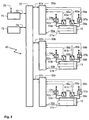
- Figure 2 shows the linear drives 10, 11 and 12, for simplification the representation in the design already mentioned above designed as a working cylinder with pistons and piston rods are.
- first linear drive 10 Components with a reference number consisting of a number and a "a” provided components assigned to the second linear drive 11 accordingly with a digit and "b" and the third Components assigned to linear drive 12 correspondingly with a Number and "c" designated.
- FIG. 2 only those assigned to the first linear drive 10 Components explained.
- the first linear drive 10 is controlled by an axis controller module 50a monitored and regulated.
- the position of his piston will detected by a sensor system 51a and via the signal line 30a reported to the axis controller module 50a.
- the first linear drive 10 is passed through on the bearing cover side Actuating means 52a pressurized with compressed air via a line 53a or vented.
- the adjusting means 52a are replaced by a compressed air supply device indicated by a double arrow supplied with compressed air.
- the actuating means 52a are represented very simplified by a proportional valve, can however also comprise other proportionally acting valves, especially a 3/3 proportional valve, so the Compressed air and targeted ventilation can be controlled.
- the Actuating means 52a are controlled by a control line 54a Axis controller module 50a controlled.
- the bearing cap pending Pressure is through one connected to line 53a Pressure sensor 55a monitors the respective Pressure values via a signal line 56a to the axis controller module 50a reports.
- the first linear drive 10 is passed through the adjusting means 57a corresponding to the adjusting means 52a via a Line 58a pressurized with compressed air or vented.
- the Adjustment means 57a are controlled by a control line 59a Axis controller module 50a controlled.
- the one on the end cover Pressure is through one connected to line 58a Pressure sensor 60a monitors the respective Pressure values via a signal line 61a to the axis controller module 50a reports.
- the pressure sensors 60a and 55a can also attached directly to the working cylinder of the linear drive 10 his. In the case of control without a pressure sensor system, the Pressure sensors 60a and 55a can also be dispensed with.
- the positioning means 52a and the adjusting means 57a can also, for example be implemented as a single 5/3 proportional valve.
- the axis controller module is via a control and signaling connection 62a 50a connected to a bus 70. Instead of bus 70 individual connection lines can also be provided his.
- a central control module 71 is also connected to the bus 70 connected via a bidirectional connection 72 as well a central compensation control module 73 via a bidirectional Connection 74.
- the central control module 71 can an interface 75 position setpoints, preferably in Cartesian world coordinates, specified for the end effector 13 become. For example, at the interface 75 Operator terminal with keyboard, mouse and monitor or a parent Master computer can be connected.
- the central control module 71 and the compensation control module 73 are from the axis controller modules 50a, 50b and 50c both with the Pressure sensors 52a, 60a, 52b, 60b, 52c and 60c reported Pressure measured values as well as from the sensors 51a, 51b and 51c determined measured position values supplied. It is also possible that the central control module 71 and the compensation control module 73 each directly with the sensors mentioned are connected. Furthermore, the central control module 71 or each of the axis controller modules 50a, 50b and 50c based on the current position measurement the current acceleration and the current speed of the runners 14a, 14b and 14c determine.
- the central control module 71 determines Axis position setpoints to be set from the default value for the individual axes of the linear drives 10, 11 and 12.
- Cartesian coordinates are in related to the parallel kinematic system or the end effector 13 Coordinates converted.
- the central control module also takes into account 71 possible collisions and determines one Path curve for the end effector 13, in which no collisions may occur.
- the central control module 71 then transmits the axis controller modules 50a, 50b and 50c each have a sequence of axis position setpoints, which the axis controller modules 50a, 50b and 50c on the linear drives assigned to them 10, 11 and 12 must be set. Furthermore, the sequences of axis position setpoints also to the compensation control module 73 transmitted.
- the axis controller modules 50a, 50b and 50c then set the Axis position setpoints each by controlling the actuating means 52a, 57a, 52b, 57b, 52b and 57c, respectively the axis controller modules 50a, 50b and 50c each the current one Position of the respective runner 14a, 14b and 14c as well the pressure conditions currently available as on the respective Take linear forces into account.
- the axis controller modules 50a, 50b and 50c also determine e.g. based on the runner speed to be set, which Frictional forces between the pistons and the profile bars 16a, 16b and 16c and between these and the runners 14a, 14b and 14c occur.
- the linear drives then depend on this 10, 11 and 12 correspondingly more or less compressed air fed.
- the axis controller modules 50a, 50b and 50c can be dimensioned very easily because this only takes one linear drive into account control in a single axis direction.
- the central control module 71 via the interface 75 can also be specified, which acceleration the End effector 13 may experience.
- the central control module depends on this 71 the axis controller modules 50a, 50b and 50c then modified sequences of axis position setpoints.
- the axis controller modules 50a, 50b and 50c setpoints for the respective acceleration of the are assigned to them assigned linear drive, which Axis controller modules 50a, 50b and 50c then control the take into account the respective positioning means.
- the compensation control module 73 Based on the axis position target values obtained from the central control module 71 determines the compensation control module 73, which nonlinear forces, i.e. which gravitational forces, Centrifugal forces, Coriolis forces and reciprocally through the Linear drives 10, 11 and 12 exerted coupling forces on the End effector 13 act. To compensate for these forces the compensation control module 73 in a function as a controller without feedback the axis controller modules 50a, 50b and 50c each on the adjusting means 52a, 57a, 52b, 57b, 52b and 57c Send pressure correction values to be set so that the non-linear forces be compensated.
- the axis controller modules 50a, 50b and 50c each on the adjusting means 52a, 57a, 52b, 57b, 52b and 57c Send pressure correction values to be set so that the non-linear forces be compensated.
- the compensation control module 73 detects those from the axis controller modules 50a, 50b and 50c reported current pressure readings and position readings and evaluates them in a function as a controller for determination the pressure correction values.
- the compensation control module 73 however expediently only such Pressure correction values that the axis controller modules 50a, 50b and 50c to compensate for those non-linear forces, that result from the coupling via the end effector 13.
- the Axis controller modules 50a, 50b and 50c one provided for this Entrance on.
- the axis controller modules 50a, 50b and 50c must therefore not to be determined by the coupling via the End effector 13 designed pressure correction values his.
- the compensation control module 73 measured values for determining Report non-linear forces.
- the central control module 71 also on the basis of the pressure measurement values of the linear drives 10, 11 and 12 determine which forces are currently acting on the Runners 14a, 14b and 14c and thus act on the end effector 13.
- a collision sensor system e.g. from ultrasonic or radar sensors be the central control module 71 in the action area of the end effector 13, possibly causing a collision Reports objects.
- the type of breakdown into individual modules of the control device 40 in FIG. 2 is only to be understood as an example, another breakdown, adding more Function modules or another grouping of the modules are easily possible.
- a central conversion module to convert between Cartesian and related to the parallel kinematic system or the end effector 13 Coordinates and vice versa can be provided by the others Modules operated.
- the axis controller modules 50a, 50b and 50c, the central control module 71 and the central compensation control module 73 also designed as program modules be executed by a central processor. Furthermore, depending on the required control accuracy, the measurement the current pressure conditions on the linear drives 10, 11 and 12 are completely or partially eliminated.
Abstract
Description
Die Erfindung betrifft ein parallelkinematisches System, bei dem zumindest zwei Aktuatoren parallelkinematisch positionierend auf eine Endeffektor-Vorrichtung wirken und jeweils mit dieser durch Verbindungsmittel in zumindest zwei Bewegungsfreiheitsgraden gelenkig verbunden sind und bei dem die Aktuatoren jeweils einen durch einen Stator entlang einer Längsbewegungsachse geführten Läufer aufweisen.The invention relates to a parallel kinematic system positioning at least two actuators in parallel kinematics act on an end effector device and each with this by connecting means in at least two degrees of freedom of movement are articulated and in which the actuators one through a stator along a longitudinal axis of movement have guided runners.
Die Erfindung betrifft ferner ein Verfahren zum Betreiben eines parallelkinematischen Systems der obengenannten Art sowie eine Steuereinrichtung und ein Programm-Modul jeweils für ein parallelkinematisches System der obengenannten Art.The invention further relates to a method for operating a parallel kinematic system of the type mentioned above as well a control device and a program module for each parallel kinematic system of the type mentioned above.
Für einen Einsatz auf dem Gebiet der Fertigungstechnik sowie in zunehmendem Maße auf dem Gebiet der Handhabungstechnik sind parallelkinematische Systeme bekannt. Bei einem parallelkinematischen System sind im Unterschied zu seriellen Systemen die angetriebenen Achsen nicht seriell einander zugeordnet, sondern greifen parallel an einer zu bewegenden Vorrichtung, beispielsweise einem Greifer an. Beispiele für seriell-kinematisch aufgebaute Systeme sind Knickarmroboter oder SCARA-Roboter (SCARA = Selective Compliance Assembly Robot). Da bei serieller Kinematik der an einer Achse jeweils angeordnete Antrieb oder Antriebs-Übertragungseinrichtung für einen Antrieb durch die jeweils seriell vorgeschalteten Antriebsachsen bewegt werden muss, sind serielle Kinematiken meist schwer und langsam.For use in the field of manufacturing technology as well increasingly in the field of handling technology parallel kinematic systems are known. With a parallel kinematic Systems are different from serial systems the driven axes are not serially assigned to each other, but grab a device to be moved in parallel, for example a gripper. Examples of serial kinematic constructed systems are articulated arm robots or SCARA robot (SCARA = Selective Compliance Assembly Robot). Because with serial kinematics the one on each axis arranged drive or drive transmission device for a drive through the respective upstream drive axes must be moved are serial kinematics mostly difficult and slow.
Bei einem parallelkinematischen System hingegen ist das Verhältnis zwischen Eigenmasse des Systems, insbesondere der bewegten Anteile des Systems und des durch das System zu bewegenden Gegenstandes, sehr viel günstiger, was eine hohe Arbeitsgeschwindigkeit sowie gute Antriebswirkungsgrade zur Folge hat. Typische parallelkinematische Systeme sind beispielsweise in dem US-amerikanischen Patent 4,976,582 beschrieben. Dort werden beispielsweise Drehantriebe zum Antrieb der jeweiligen Antriebsachsen eingesetzt, mit denen Parallelstab-Fußpunkte auf einem Kreisbogen bewegt werden. Alternativ sind als "Motoren" bezeichnete Linearantriebe vorgesehen, die über Verstärker durch einen Steuercomputer überwacht und gesteuert werden. Es werden also elektrische Antriebe eingesetzt. Diese sind jedoch teuer und aufgrund der zu beschleunigenden und zu bewegenden Massen teilweise auch träge.In the case of a parallel kinematic system, on the other hand, the ratio is between dead weight of the system, especially the moving one Proportions of the system and those to be moved by the system Object, much cheaper, what a high working speed as well as good drive efficiency for Consequence. Typical parallel kinematic systems are, for example in U.S. Patent 4,976,582. There, for example, rotary drives become drives of the respective drive axles with which parallel rod base points are used be moved on an arc. Alternatively linear drives designated as "motors" are provided, which is monitored via amplifiers by a control computer and be controlled. So there are electric drives used. However, these are expensive and due to the masses to be accelerated and moved sluggish.
Es ist daher Aufgabe der vorliegenden Aufgabe, ein kostengünstiges parallelkinematisches System zu schaffen, das eine hohe Positioniergenauigkeit aufweist.It is therefore the task of the present task, an inexpensive one parallel kinematic system to create one has high positioning accuracy.
Diese Aufgabe wird gelöst durch ein parallelkinematisches System der eingangs genannten Art, wobei die Aktuatoren als durch fluidische Antriebswirkung angetriebene Antriebe ausgebildet sind, wobei pro Aktuator jeweils kontinuierlich wirkende Stellmittel zur Beeinflussung der fluidischen Antriebswirkung auf den Läufer vorgesehen sind, wobei pro Aktuator Positionserfassungsmittel zur Erfassung der Position des Läufers vorgesehen sind und wobei eine Steuereinrichtung zur Steuerung der Stellmittel in Abhängigkeit von den jeweiligen von den Positionserfassungsmitteln erfassten und an die Steuereinrichtung gemeldeten Positionen der Läufer vorgesehen sind, so dass die Endeffektor-Vorrichtung durch Positionieren der Läufer relativ zu den ihnen zugeordneten Statoren positionierbar ist.This problem is solved by a parallel kinematic System of the type mentioned, wherein the actuators as Drives formed by fluidic drive action are, with each actuator acting continuously Adjustment means for influencing the fluidic drive effect are provided on the rotor, with each actuator Position detection means for detecting the position of the runner are provided and wherein a control device for Control of the actuating means depending on the respective detected by the position detection means and to the control device reported positions of the runners are so that the end effector device by positioning the rotor can be positioned relative to the stators assigned to it is.
Die Aufgabe wird ferner gelöst durch ein Verfahren gemäß der technischen Lehre des Anspruchs 17, eine Steuereinrichtung gemäß der technischen Lehre des Anspruchs 19 sowie ein Programm-Modul gemäß der technischen Lehre des Anspruchs 20.The object is further achieved by a method according to the Technical teaching of claim 17, a control device according to the technical teaching of claim 19 and a program module according to the technical teaching of claim 20.
Der Erfindung liegt dabei der Gedanke zugrunde, ein parallelkinematisches System mit fluidtechnischen, insbesondere mit pneumatischen Antrieben auszurüsten. Die Läufer dieser Antriebe können erfindungsgemäß jedoch nicht nur zwischen den jeweiligen Endpositionen in den sie jeweils führenden Statoren im sogenannten "Punkt-zu-Punkt"-Modus verfahren werden, sondern beliebige Zwischenpositionen einnehmen, weisen also ein sogenanntes Bahnfolgeverhalten auf. Dazu sind jedem Antrieb Stellmittel, insbesondere jeweils zumindest ein Proportionalventil zugeordnet, über das die fluidtechnische Antriebswirkung auf den jeweiligen Läufer, insbesondere die Wirkung von Druckluft kontinuierlich, das heißt stetig, einstellbar ist. Die Stellmittel werden durch eine Steuereinrichtung, z.B. eine Mikroprozessorsteuerung, in Abhängigkeit der von Erfassungsmitteln, z.B. von Sensoren, erfassten Positionen der Läufer so angesteuert, dass die jeweiligen Läufer vorbestimmte Positionen in den Statoren einnehmen und damit über die Positionierung der Läufer die sogenannte Endeffektor-Vorrichtung positioniert wird. An der Endeffektor-Vorrichtung ist beispielsweise ein Greifer, ein Bohrer, eine Ansaugvorrichtung oder eine sonstige Handhabungs- und/oder Antriebsvorrichtung angeordnet. Die eingesetzten pneumatischen Antriebe sind kostengünstig und erlauben eine präzise Positionierung bei geringen Bahn-Konturfehlern während des Verfahrvorgangs der Endeffektor-Vorrichtung, so dass sogenannte "Pick-and-Place"-Aufgaben wie auch sogenannte "Bahnaufgaben" durch das erfindungsgemäße parallelkinematische System gelöst werden können. Dabei sind hohe Beschleunigungs- und Geschwindigkeitswerte zu erzielen, da die bewegte Masse der fluitechnischen Antriebe verhältnismäßig gering ist.The invention is based on the idea of a parallel kinematic System with fluid technology, especially with pneumatic drives. The runners of these drives However, according to the invention, not only between the respective end positions in the stators leading them be operated in the so-called "point-to-point" mode, but take any intermediate positions, so point a so-called path following behavior. This is what drives everyone Adjusting means, in particular at least one proportional valve assigned, via which the fluid power drive effect on the respective runner, especially the Effect of compressed air continuously, i.e. continuously, adjustable is. The actuating means are controlled by a control device, e.g. a microprocessor control, depending that of detection means, e.g. of sensors, detected positions the runner is controlled so that the respective runner Assume predetermined positions in the stators and thus the so-called end effector device via the positioning of the runners is positioned. At the end effector device is, for example, a gripper, a drill, a Suction device or other handling and / or Drive device arranged. The pneumatic used Drives are inexpensive and allow precise Positioning with small path contour errors during the Travel process of the end effector device, so-called "Pick-and-place" tasks as well as so-called "Path tasks" through the parallel kinematic according to the invention System can be solved. Here are high acceleration and to achieve speed values since the moving Mass of the fluitechnical drives relatively small is.
Weitere vorteilhafte Ausgestaltungen der Erfindung finden sich in den abhängigen Ansprüchen sowie in der Beschreibung.Find further advantageous embodiments of the invention themselves in the dependent claims as well as in the description.
Zweckmäßigerweise steuert die Steuereinrichtung die Stellmittel so an, dass die Endeffektor-Vorrichtung bei ihrer bedarfsgemäßen Positionierung eine definierte Bahnkurve durchläuft, die Endeffektor-Vorrichtung also Zwischenpositionen in einer vorbestimmten zeitlichen Abfolge überfährt. Damit kann sichergestellt werden, dass die Endeffektor-Vorrichtung nicht mit eventuell in ihrem Arbeitsbereich befindlichen Gegenständen kollidiert. The control device expediently controls the adjusting means in such a way that the end effector device, when required Positioning runs through a defined trajectory, the end effector device in intermediate positions runs over a predetermined time sequence. So that can ensure that the end effector device is not with any objects in their work area collided.
Ferner überwacht die Steuereinrichtung die Aktuatoren vorteilhafterweise dahingehend, dass die Endeffektor-Vorrichtung zwar so stark wie möglich, jedoch nicht übermäßig beschleunigt oder abgebremst wird, beispielsweise wenn ein mit Flüssigkeit gefülltes Gefäß durch die Endeffektor-Vorrichtung transportiert wird. Ferner kann die Steuereinrichtung dabei auch die jeweilige Verfahrgeschwindigkeit der Endeffektor-Vorrichtung kontrollieren und steuern.Furthermore, the control device advantageously monitors the actuators in that the end effector device as much as possible, but not overly accelerated or is slowed down, for example if one with liquid filled vessel through the end effector device is transported. Furthermore, the control device can also the respective travel speed of the end effector device control and control.
In einer vorteilhaften Weiterbildung der Erfindung bilden die Statoren beziehungsweise Gehäuse der Aktuatoren tragende Bauteile des Vorrichtungsgestells des parallelkinematischen Systems, so dass an sich für den Aufbau eines Gestelles notwendige Gestellbauteile entfallen können und eine besonders leichte und kostengünstige Konstruktion entsteht.In an advantageous development of the invention, the Stators or housings of the components carrying the actuators the device frame of the parallel kinematic system, so that in itself necessary for the construction of a frame Frame components can be omitted and a special one light and inexpensive construction arises.
In einer bevorzugten Variante ist die Steuereinrichtung modular aufgebaut und weist dabei beispielsweise ein Zentral-Steuermodul sowie dezentrale, den jeweiligen Antrieben zugeordnete, sogenannte Achsreglermodule auf. Die Achsreglermodule stellen dann von dem Zentral-Steuermodul vorgegebene Positionen der jeweiligen Läufer ein und korrigieren gegebenenfalls Abweichungen der Positions-Ist-Werte von durch das Zentral-Steuermodul vorgegebenen Positions-Soll-Werten. Es ist jedoch auch möglich, dass die Steuereinrichtung als zentrale Steuereinrichtung ausgebildet ist und eine von der Steuereinrichtung eingesetzte Software in der oben beschriebenen Weise modular aufgebaut ist. In a preferred variant, the control device is modular constructed and has, for example, a central control module as well as decentralized, assigned to the respective drives, so-called axis controller modules. The axis controller modules then set positions predetermined by the central control module of the respective runner and correct if necessary Deviations of the actual position values from by Central control module predetermined position target values. It However, it is also possible for the control device to be the central one Control device is formed and one of the control device software used in the above Way is modular.
Zweckmäßigerweise wird nicht nur die Position der jeweiligen Läufer erfasst, sondern es sind auch Krafterfassungsmittel vorgesehen, die die jeweiligen auf die Aktuatoren, insbesondere auf deren Läufer einwirkenden Kräfte erfassen. Dadurch wird es beispielsweise möglich, dass über die Endeffektor-Vorrichtung auf den jeweiligen Aktuator einwirkenden Rückwirkungskräfte erfasst werden und durch eines der erwähnten Achsreglermodule und/oder durch das Zentral-Steuermodul kompensiert werden.Expedient not only the position of the respective Runners recorded, but there are also force detection means provided that the respective on the actuators, in particular detect forces acting on their runners. Thereby it becomes possible, for example, that the end effector device reaction forces acting on the respective actuator be recorded and by one of the mentioned Axis controller modules and / or compensated by the central control module become.
In einer weiteren vorteilhaften Variante der Erfindung ermittelt die Steuereinrichtung, insbesondere das Zentral-Steuermodul, inwieweit Nichtlinear-Kräfte, insbesondere Gravitationskräft, Zentrifugalkräfte, Corioliskräfte und Koppelkräfte, auf die Endeffektor-Vorrichtung einwirken und steuern die Stellmittel, diese Nichtlinear-Kräften gegebenenfalls kompensierend, an. Dazu wird vorteilhafterweise in Fortsetzung der modularen Vorgehensweise innerhalb der Steuereinrichtung ein Kompensationsregelmodul eingesetzt. Das Kompensationsregelmodul steuert die Stellmittel zur Kompensation der Nichtlinear-Kräfte entweder direkt an oder zweckmäßigerweise indirekt über die Achsreglermodule, die dann einen entsprechend dafür vorgesehenen "Kompensationskraft-Eingang" aufweisen.Determined in a further advantageous variant of the invention the control device, in particular the central control module, to what extent non-linear forces, especially gravitational forces, Centrifugal forces, Coriolis forces and coupling forces, act on and control the end effector device Adjusting means, if necessary compensating for these non-linear forces, on. This is advantageously continued in the modular procedure within the control device Compensation control module used. The compensation control module controls the adjusting means for the compensation of the non-linear forces either directly to or expediently indirectly via the axis controller modules, which are then used accordingly have provided "compensation force input".
Im Folgenden werden die Erfindung und ihre Vorteile anhand von Ausführungsbeispielen unter Zuhilfenahme der Zeichnungen dargestellt. Es zeigen
- Figur 1
- ein Ausführungsbeispiel eines erfindungsgemäßen parallelkinematischen Systemes sowie
- Figur 2
- ein Ausführungsbeispiel einer erfindungsgemäßen Steuereinrichtung.
- Figure 1
- an embodiment of a parallel kinematic system according to the invention and
- Figure 2
- an embodiment of a control device according to the invention.
Figur 1 zeigt als Aktuatoren drei pneumatische Linearantriebe
10, 11 und 12, die säulenartig mit vertikaler Ausrichtung angeordnet
sind und sich zwischen einer im Wesentlichen sternförmigen
Grundplatte 8 und einer gleichartig wie die Grundplatte
8 gestalteten Deckplatte 9 solchermaßen erstrecken,
dass zwischen den Längsachsen der Linearantriebe 10, 11 und
12 ein Arbeitsraum vorzugsweise in Gestalt eines regulären
Prismas auf der Grundfläche eines gleichschenkligen Dreiecks
aufgespannt wird. Dabei zeigen die Längsachsen der Linearantriebe
10, 11 und 12 jeweils einenends senkrecht auf die Eckpunkte
des auf der Grundplatte 8 aufgespannten gleichschenkligen
Dreiecks und anderenends auf die Eckpunkte des auf der
Deckplatte 9 aufgespannten gleichschenkligen Dreiecks. Auf
der Grundplatte 8 ist ein hexagonaler Arbeitstisch 7 angeordnet.
Auf diese Weise ist ein Vorrichtungsgestell 6 des parallelkinematischen
Systems definiert.Figure 1 shows three pneumatic linear drives as
Anstelle der Grundplatte 8 und der Deckplatte 9 könnten auch
andere, die Linearantriebe 10, 11 und 12 gegeneinander abstützende
Stützmittel vorgesehen sein. Vorteilhaft ist jedenfalls,
wenn die Linearantriebe 10, 11 und 12 wie beim Ausführungsbeispiel
tragende Gestellbauteile des Vorrichtungsgestelles
6 des parallelkinematischen Systems bilden.Instead of the
Es ist jedoch auch möglich, dass bei dem Vorrichtungsgestell
6 die Deckplatte 9 entfällt oder näher beieinander liegende
Eckpunkte aufweist als die Grundplatte 8 und die Linearantriebe
10, 11 und 12 dann einen pyramidenförmigen oder Pyramidenstumpf-förmigen
Arbeitsraum aufspannen. Ferner können
die Linearantriebe 10, 11 und 12 je nach Bedarf auch beliebig
andersartig angeordnet oder geneigt sein als in Figur 1. Die
Linearantriebe 10, 11 und 12 können beispielsweise auch parallel
nebeneinander angeordnet sein. Die Deckplatte 9 kann
z.B. auch an einer Deckenfläche oder Seitenwandfläche aufgehängt
sein und die Grundplatte 8 entfallen.However, it is also possible for the
Der erste Linearantrieb 10 weist einen Läufer 14a auf, der
durch einen Stator 15a geführt wird. Bei dem zweiten Linearantrieb
11 ist ein Läufer 14b in einem Stator 15b, bei dem
dritten Linearantrieb 12 ein Läufer 14c in einem Läufer 15c
geführt. Mit den Läufern 14a, 14b und 14c ist eine Endeffektor-Vorrichtung
13 verbunden, die im Folgenden nur als
"Endeffektor 13" bezeichnet wird. An dem Endeffektor 13 ist
beispielsweise ein Greifer, ein Bohrer oder wie im vorliegenden
Fall eine pneumatische Ansaugvorrichtung angebracht, die
durch Positionieren der Läufer 14a, 14b und 14c bewegt wird.The first
Da die Linearantriebe 10, 11 und 12 jeweils grundsätzlich
gleich aufgebaut sind, wird im Folgenden nur der erste Linearantrieb
10 näher erläutert, dessen Bestandteile jeweils mit
Bezugzeichen versehen sind, die aus einer Ziffer und einem an
die Ziffer angefügten "a" bestehen. Jeweils den Bestandteilen
des Linearantriebs 10 entsprechende Bestandteile des zweiten
Linearantriebs 11 sind mit denselben Ziffern, jedoch mit einem
angefügten "b", entsprechende Bestandteile des dritten
Linearantriebs 12 mit einem angefügten "c" bezeichnet. Since the
Der Stator 14a umfasst im Wesentlichen einen als langgestreckter
Hohlkörper ausgeführten Profilstab 16a, der in axialer
Längsrichtung einenends durch einen auf der Grundplatte
8 mit Hilfe von Winkellaschen befestigten Fuß 17a abgeschlossen
und gehalten wird, anderenends durch ein mit der
Deckplatte 9 verbundenes Kopfstück 18a abgeschlossen wird.
Für diese Abschlusselemente wären aber auch andere Formgebungen
möglich. Ferner können auch die Winkellaschen entfallen,
wenn der Fuß 17a beispielsweise mit der Grundplatte 8 von deren
Unterseite her verschraubt wird. Der Profilstab 16a weist
im vorliegenden Fall äußerlich einen quadratischen Querschnitt
auf. Im Inneren des Profilstabs 16a erstreckt sich in
Längsrichtung ein in Figur 1 nicht sichtbarer Hohlraum über
die gesamte Länge des Profilstabs 16a. Durch in dem Fuß 17a
sowie in dem Kopfstück 18a befindliche, nicht sichtbare Ein-
und Auslässe kann der Hohlraum des das Gehäuse des Linearantriebs
10 bildenden Profilstabes 16a mit Druckluft beaufschlagt
werden oder entlüftet werden, so dass ein sich in dem
Hohlraum des Profilstabes 16a befindlicher, in Figur 1 nicht
sichtbarer Kolben in Längsrichtung des Profilstabs 16a zu dem
Kopfstück 18a oder dem Fuß 17a hin bewegt wird.The
An dem Kolben ist ein in Figur 1 nicht sichtbarer Mitnehmer
angebracht, der aus dem Hohlraum des Profilstabes 16a durch
einen sich in Längsrichtung des Profilstabes 16a erstreckenden
Schlitz 19a herausragt und mit dem Läufer 14a verbunden
ist. Dadurch wird der Läufer 14a zusammen mit dem Kolben bewegt.
Damit aus dem Schlitz 19a keine Druckluft entweichen
kann, ist dieser durch ein Dichtband abgedichtet, das durch
den Mitnehmer oder den Kolben lokal abgehoben werden kann. At the piston is a driver not visible in Figure 1
attached, which from the cavity of the profile rod 16a
an extending in the longitudinal direction of the profile bar 16a
Slot 19a protrudes and is connected to
Der Läufer 14a ist als Schlitten mit einem z.B. L-förmigen
Profil ausgeführt, wobei ein Schenkel des Profiles mit dem
Mitnehmer verbunden ist und der andere Schenkel den Profilstab
16a umgreift. Der Läufer 14a wird durch eine aus Gründen
der Übersichtlichkeit nicht dargestellte, an dem Profilstab
16a angeordnete Längsführung sicher und präzise geführt.The
Da für den ersten Linearantrieb 10 keinerlei Bauraum erfordernde
Kolbenstange notwendig ist, wird der erste Linearantrieb
10 auch als "kolbenstangenloser Linearantrieb" bezeichnet.
Er kann prinzipiell von an sich bekannter Bauart sein.
Es ist jedoch auch möglich, dass anstatt kolbenstangenloser
Linearantriebe solche mit Kolbenstangen eingesetzt werden,
insbesondere auch übliche pneumatische Zylinder. Auch Mischformen
beider Antriebstypen in einem parallelkinematischen
System sind ohne Weiteres möglich. Ferner kann der Läufer 14a
von dem Kolben auch anstatt durch mechanische Mitnehmerwirkung
auch beispielsweise durch Magnetwirkung bewegt werden,
so dass die Schlitze 19a, 19b, 19c nicht notwendig sind.Since no space is required for the first
Der Läufer 14a ist über parallele Verbindungsstäbe 20a und
21a mit dem Endeffektor 13 verbunden. Die Verbindungsstäbe
20a und 21a bestehen im vorliegenden Fall aus besonders
leichtem, jedoch belastbarem und verwindungssteifem Kohlefasermaterial.
An den Enden der Verbindungsstäbe 20a und 21a
sind jeweils Kugelgelenke 23a, 24a, 25a und 26a angeordnet,
mit denen die Verbindungsstäbe 20a und 21a einenends mit dem
Läufer 14a und anderenends mit dem Endeffektor 13 verbunden
sind. Die parallelen Verbindungsstäbe 20a und 21a sowie die
Kugelgelenke 23a, 24a, 25a und 26a bilden Verbindungsmittel,
mit denen der Läufer 14a in zumindest zwei Bewegungsfreiheitsgraden
mit dem Endeffektor 13 gelenkig verbunden ist.
Anstatt der Kugelgelenke können beispielsweise auch Kardangelenke
oder sonstige Gelenkanordnungen mit zumindest zwei
Bewegungsfreiheitsgraden eingesetzt werden.The
Ähnlich wie der Läufer 14a sind auch die Läufer 14b und 14c
durch parallele Verbindungsstäbe 20b und 21b bzw. 20c und 21c
sowie durch den Kugelgelenken 23a, 24a, 25a und 26a entsprechende
Kugelgelenke 23b-26b bzw. 23c-26c jeweils mit dem Endeffektor
13 verbunden. Die Verbindungsstäbe 20c und 21c sind
jedoch in Figur 1 zum Teil durch die Verbindungsstäbe 20b und
21b sowie den zweiten Linearantrieb 11 verdeckt. Durch die
Verwendung paralleler Verbindungsstäbe wird im vorliegenden
Fall eine rotatorische Bewegung des Endeffektors 13 unterdrückt,
eine translatorische Bewegung mit drei Freiheitsgraden
hingegen ermöglicht.The runners 14b and 14c are similar to the
Werden geringere Anforderungen an die Qualität der Bewegung
des Endeffektors 13 oder dessen Belastbarkeit gestellt, kann
beispielsweise zumindest bei einem der Linearantriebe nur ein
Verbindungsstab statt der parallelen Verbindungsstäbe verwendet
werden. Ferner ist es bei anderen Anforderungen an die
Stabilisierung und Antriebswirkung auf den Endeffektor 13
möglich, dass einer der Linearantriebe ganz entfällt, insbesondere
wenn die Ankoppelpunkte von jeweils zwei parallelen
Verbindungsstäben an einem Läufer befestigt sind, oder dass
einer der Linearantriebe durch eine antriebslose Anordnung
aus Profilstab und Läufer ersetzt wird. Weiter können weitere,
den Endeffektor 13 positionierende und stabilisierende
Linearantriebe hinzukommen. Wenn nicht nur die Position des
Endeffektors 13, sondern auch dessen Orientierung vorgegeben
werden soll, können in einer weiteren Variante auch beispielsweise
sechs Linearantriebe vorgesehen sein, die mit dem
Endeffektor 13 jeweils über lediglich einen Verbindungsstab
verbunden sind.Will lower demands on the quality of the movement
the
Bei der Anordnung in Figur 1 bilden die Statoren der Linearantriebe
10, 11 und 12, insbesondere deren Profilstäbe 16a,
16b, 16c bereits tragende Gestellbauteile des parallelkinematischen
Systems, so dass kaum weitere Gestellbauteile notwendig
sind. Die Grundplatte 8 und die Deckplatte 9 können
sogar ganz entfallen, wenn die Linearantriebe 10, 11 und 12
über deren Kopfstücke 18a, 18b, 18c unmittelbar miteinander
verbunden sind.In the arrangement in Figure 1, the stators form the
Von einer Ventilanordnung 27 führen jeweils zwei Druckluft-Verbindungen
28a, 28b und 28c zu den Füßen 17a, 17b und 17c
der Linearantriebe 10, 11 und 12. In den Profilstäben 16a,
16b und 16c verlaufen integrierte Kanäle, die die Verbindung
zu den jeweiligen Kopfstücken der Linearantriebe herstellen.
Die Ventilanordnung 27 wird über eine Leitung 29 von einer
nicht dargestellten Druckluft-Quelle mit Druckluft versorgt.Two compressed air connections each lead from a
Die Ventilanordnung 27 umfasst für jeden der Linearantriebe
10, 11 und 12 Stellmittel, die die fluidische Antriebswirkung
auf den jeweiligen Läufer eines Linearantriebs kontinuierlich
wirkend beeinflussen. Über diese Stellmittel kann Druckluft
dosiert sowohl auf Seiten der Kopfstücke 18a, 18b und 18c als
auch auf Seiten der Füße 17a, 17b und 17c, also zu beiden
Seiten des jeweiligen Kolbens, in die Profilstäbe 16a, 16b
und 16c eingespeist werden. Ferner können über diese Stellmittel
die Profilstäbe 16a, 16b und 16c sowohl auf Seiten der
Kopfstücke 18a, 18b und 18c als auch auf Seiten der Füße 17a,
17b und 17c kontrolliert entlüftet werden. Dazu sind die
Stellmittel jeweils pro Linearantrieb mit zumindest einem und
vorzugsweise zwei Proportionalventilen, jeweils mit der Funktionalität
eines 3/3-Ventiles, ausgerüstet, so dass der Druck
auf Seiten des jeweiligen Kopfstückes und auf Seiten des jeweiligen
Fußes jeweils individuell eingestellt werden kann.
Es ist beispielsweise auch möglich, dass anstatt zweier jeweils
als 3/3-Ventile funktionierender Proportionalventile
ein Ventil mit der Funktionalität eines 5/3-Proportionalventiles
vorgesehen ist.The
Es ist jedoch grundsätzlich auch möglich, dass die Stellmittel
jeweils individuell einstellbare Fördermittel aufweisen
oder dass beispielsweise nur über die Füße Druckluft zugeführt
wird, wobei dann die Kolben des Linearantriebe entweder
durch mechanische Federn, durch sogenannte Luftfedern oder
durch Schwerkraft zurückgestellt werden. Die Ventilanordnung
27 kann auch dezentral aufgebaut sein, wobei die jeweils zu
einem Linearantrieb gehörenden Stellmittel auch in den Linearantrieb
integriert sein können.In principle, however, it is also possible for the adjusting means
each have individually adjustable funding
or that, for example, compressed air is only supplied via the feet
is, then the pistons of the linear drives either
by mechanical springs, by so-called air springs or
be reset by gravity. The
An den Linearantrieben 10, 11 und 12 sind jeweils in Figur 1
nicht sichtbare Positionserfassungsmittel zur Erfassung der
Positionen der Läufer 14a, 14b und 14c angeordnet. Die Positionserfassungsmittel
sind jeweils im Innern der Statoren
15a, 15b und 15c angeordnete Sensoren die beispielsweise
durch Radar oder Ultraschall die Position der jeweiligen Läufer
14a, 14b und 14c erfassen. Die Wegemessung durch die Positionserfassungsmittel
kann auch z.B. auf magnetostriktivem
oder induktivem Weg erfolgen, wobei insbesondere in diesen
Fällen die dazu erforderliche Sensorik auch entlang der Profilstäbe
16a, 16b und 16c angebracht sein kann.The linear drives 10, 11 and 12 are each in FIG. 1
Invisible position detection means for recording the
Positions of the
Von den Positionserfassungsmitteln führen Meldeleitungen 30a,
30b und 30c zu einer lediglich schematisch dargestellten
Steuereinrichtung 40, die die Funktionen des parallelkinematischen
Systems steuert. Die Steuereinrichtung 40 weist ein
Ein-/Ausgabemodul 41, einen Prozessor 42 und Speichermittel
43 auf, die jeweils durch nicht gezeigte Verbindungen untereinander
verbunden sind. Die Steuereinrichtung 40 wird durch
ein Betriebssystem sowie durch Software-Module betrieben, die
in dem Speichermittel 43 gespeichert sind und deren Programmcode-Sequenzen
durch den Prozessor 42 ausgeführt werden.
Das Speichermittel 43 umfasst beispielsweise RAM-Module (RAM
= Random Access Memory) für temporär zu speichernde Daten sowie
Flash-Memory-Module und/oder ROM-Module (ROM = Read Only
Memory) für langfristig zu speichernde Daten. Von der Steuer-einrichtung
40 führt eine Steuerleitung 44 zu der Ventilanordnung
27 zur deren Steuerung und damit zur Beeinflussung
der Linearantriebe 10, 11 und 12. Über eine Meldeleitung
45 kann die Ventilanordnung 27 der Steuereinrichtung 40 aktuelle
Zustände und Einstellungen rückmelden. Die Meldeleitungen
30a, 30b und 30c sowie die Steuerleitung 44 und die
Meldeleitung 45 können sich auch auf einem Bus befinden.
Die Steuereinrichtung 40 erfasst die jeweiligen von den Positionserfassungsmitteln
über die Meldeleitungen 30a, 30b und
30c an die Steuereinrichtung 40 gemeldeten Positionen der
Läufer 14a, 14b und 14c und sendet in Abhängigkeit der jewei-ligen
Positionen Steuerbefehle über die Steuerleitung 44 an
die Ventilanordnung 27. Über diese werden dann die Linearantriebe
10, 11 und 12 entweder über die Füße 17a, 17b und 17c
oder über die Kopfstücke 18a, 18b und 18c jeweils so mit
Druckluft beaufschlagt oder entlüftet, dass die Läufer 14a,
14b und 14c in den Profilstäben 16a, 16b und 16c verfahren
werden und eine durch die Steuereinrichtung 40 gewünschte Position
einnehmen. Über die Läufer 14a, 14b und 14c wird auch
der Endeffektor 13 entsprechend der Vorgaben der Steuereinrichtung
40 bewegt.The
Die Steuereinrichtung 40 gibt jedoch für die Läufer 14a, 14b
und 14c nicht nur deren jeweilige, für eine bestimmte Positionierung
des Endeffektors 13 notwendige End-Position vor,
sondern steuert auch das Verfahren der Läufer 14a, 14b und
14c zwischen diesen End-Positionen, so dass der Endeffektor
13 eine vorbestimmte Bahnkurve durchläuft. Auf diese Weise
wird vermieden, das der Endeffektor 13 bei einem Positioniervorgang
mit eventuell auf dem Arbeitstisch 7 befindlichen
Gegenständen kollidiert. Ferner sorgt die Steuereinrichtung
40 durch entsprechende Ansteuerung der Ventilanordnung 27 dafür,
dass der Endeffektor 13 zwar schnellstmöglich beschleunigt
oder abgebremst wird, jedoch zu hohe Beschleunigungswerte
vermieden werden. The
Ein beispielhafter funktionaler Aufbau der Steuereinrichtung
40 ist in Figur 2 gezeigt. Die Steuereinrichtung 40 ist in
dem Ausführungsbeispiel in Figur 2 modular aufgebaut, wobei
die Module als einzelne Software-Module innerhalb einer zentralen
Steuereinrichtung 40 ausgebildet sein können oder als
dezentrale Steuermodule, die beispielsweise an einem gemeinsamen
Bus arbeiten. Solche dezentralen Steuermodule können
auch ganz oder teilweise als analoge elektrische Schaltungen
aufgebaut sein oder jeweils einen Prozessor, Speicher,
Ein-/Ausgabebaugruppen und eine Steuerungssoftware aufweisen.
Mischformen sind ebenfalls möglich.An exemplary functional structure of the
Figur 2 zeigt die Linearantriebe 10, 11 und 12, die zur Vereinfachung
der Darstellung in der oben bereits erwähnten Bauform
als Arbeitszylinder mit Kolben und Kolbenstangen ausgeführt
sind. Wie bereits anhand der Figur 1 praktiziert, sind
auch im Folgenden dem ersten Linearantrieb 10 zugeordnete
Komponenten mit einem Bezugzeichen aus einer Ziffer und einem
"a" versehen, dem zweiten Linearantrieb 11 zugeordnete Komponenten
entsprechend mit einer Ziffer und "b" und dem dritten
Linearantrieb 12 zugeordnete Komponenten entsprechend mit einer
Ziffer und "c" bezeichnet. Zur Vereinfachung werden auch
in Figur 2 nur die dem ersten Linearantrieb 10 zugeordneten
Komponenten erläutert.Figure 2 shows the
Der erste Linearantrieb 10 wird durch ein Achsreglermodul 50a
überwacht und geregelt. Die Position seines Kolbens wird
durch eine Sensorik 51a erfasst und über die Meldeleitung 30a
an das Achsreglermodul 50a gemeldet. The first
Lagerdeckelseitig wird der erste Linearantrieb 10 durch
Stellmittel 52a über eine Leitung 53a mit Druckluft beaufschlagt
oder entlüftet. Die Stellmittel 52a werden durch eine
durch einen Doppelpfeil angedeutete Druckluft-Versorgungseinrichtung
mit Druckluft versorgt. Die Stellmittel 52a sind
stark vereinfachend durch ein Proportionalventil dargestellt,
können jedoch auch andere proportional wirkende Ventile umfassen,
insbesondere ein 3/3-Proportionalventil, so dass die
Druckluft sowie eine gezielte Entlüftung steuerbar sind. Die
Stellmittel 52a werden über eine Steuerleitung 54a von dem
Achsreglermodul 50a gesteuert. Der lagerdeckelseitig anstehende
Druck wird durch einen an die Leitung 53a angeschlossenen
Drucksensor 55a überwacht, der die jeweiligen
Druckwerte über eine Meldeleitung 56a an das Achsreglermodul
50a meldet.The first
Abschlussdeckelseitig wird der erste Linearantrieb 10 durch
den Stellmitteln 52a entsprechende Stellmittel 57a über eine
Leitung 58a mit Druckluft beaufschlagt oder entlüftet. Die
Stellmittel 57a werden über eine Steuerleitung 59a von dem
Achsreglermodul 50a gesteuert. Der abschlussdeckelseitig anstehende
Druck wird durch einen an die Leitung 58a angeschlossenen
Drucksensor 60a überwacht, der die jeweiligen
Druckwerte über eine Meldeleitung 61a an das Achsreglermodul
50a meldet. Die Drucksensoren 60a und 55a können aber auch
direkt am Arbeitszylinder des Linearantriebs 10 angebracht
sein. Bei einer Regelung ohne Drucksensorik kann auf die
Drucksensoren 60a und 55a auch verzichtet werden. Die Stellmitteln
52a und die Stellmittel 57a können auch beispielsweise
als ein einziges 5/3-Proportionalventil realisiert sein. On the end cover side, the first
Über eine Steuer- und Meldeverbindung 62a ist das Achsreglermodul
50a mit einem Bus 70 verbunden. Anstatt des Busses 70
können auch individuelle Verbindungsleitungen vorgesehen
sein. An den Bus 70 sind ferner ein Zentral-Steuermodul 71
über eine bidirektionale Verbindung 72 angeschlossen sowie
ein zentrales Kompensationsregelmodul 73 über eine bidirektionale
Verbindung 74. Dem Zentral-Steuermodul 71 können über
eine Schnittstelle 75 Positions-Sollwerte, vorzugsweise in
kartesischen Weltkoordinaten, für den Endeffektor 13 vorgegeben
werden. An die Schnittstelle 75 kann beispielsweise ein
Bediener-Terminal mit Tastatur, Maus und Monitor oder ein übergeordneter
Leitrechner angeschlossen werden. Das Zentral-Steuermodul
71 und das Kompensationsregelmodul 73 werden von
den Achsreglermodulen 50a, 50b und 50c sowohl mit von den
Drucksensoren 52a, 60a, 52b, 60b, 52c und 60c gemeldeten
Druckmesswerten als auch mit von den Sensoren 51a, 51b und
51c ermittelten Positionsmesswerten versorgt. Es ist auch
möglich, dass das Zentral-Steuermodul 71 und das Kompensationsregelmodul
73 jeweils direkt mit den genannten Sensoren
verbunden sind. Ferner kann das Zentral-Steuermodul 71 oder
auch jedes der Achsreglermodule 50a, 50b und 50c anhand der
jeweiligen Positionsmesswerten die momentane Beschleunigung
und die momentane Geschwindigkeit der Läufer 14a, 14b und 14c
ermitteln.The axis controller module is via a control and
Wird dem Zentral-Steuermodul 71 über die Schnittstelle 75 ein
Vorgabewert für eine einzustellende Position für den Endeffektor
13 vorgegeben, ermittelt das Zentral-Steuermodul 71
aus dem Vorgabewert einzustellende Achspositions-Sollwerte
für die einzelnen Achsen der Linearantriebe 10, 11 und 12. Will the
Dabei werden gegebenenfalls kartesische Koordinaten in auf
das parallelkinematische System oder den Endeffektor 13 bezogene
Koordinaten umgerechnet. Ferner berücksichtigt das Zentral-Steuermodul
71 mögliche Kollisionen und ermittelt eine
Bahnkurve für den Endeffektor 13, bei dem keine Kollisionen
auftreten können. Das Zentral-Steuermodul 71 übermittelt dann
den Achsreglermodulen 50a, 50b und 50c jeweils eine Sequenz
von Achspositions-Sollwerten, die die Achsreglermodule 50a,
50b und 50c an den ihnen jeweils zugeordneten Linearantrieben
10, 11 und 12 einzustellen haben. Ferner werden die Sequenzen
von Achspositions-Sollwerten auch an das Kompensationsregelmodul
73 übertragen.If necessary, Cartesian coordinates are in
related to the parallel kinematic system or the
Die Achsreglermodule 50a, 50b und 50c stellen dann die
Achspositions-Sollwerte jeweils durch Ansteuerung der Stellmittel
52a, 57a, 52b, 57b, 52b und 57c entsprechend ein, wobei
die Achsreglermodule 50a, 50b und 50c jeweils die momentane
Position des jeweiligen Läufers 14a, 14b und 14c sowie
die momentan vorhandenen Druckverhältnisse als auf den jeweiligen
Linearantrieb einwirkende Kräfte berücksichtigen.
Ferner ermitteln die Achsreglermodule 50a, 50b und 50c z.B.
anhand der einzustellenden Läufergeschwindigkeit, welche
Reibkräfte jeweils zwischen den Kolben und den Profilstäben
16a, 16b und 16c sowie zwischen diesen und den Läufern 14a,
14b und 14c auftreten. Davon abhängig wird dann den Linearantrieben
10, 11 und 12 entsprechend mehr oder weniger Druckluft
zugeführt. Insgesamt können die Achsreglermodule 50a,
50b und 50c jedoch sehr leicht dimensioniert werden, weil
diese nämlich nur jeweils einen Linearantrieb unter Berücksichtigung
einer einzigen Achsrichtung regeln. The
Bei Bedarf kann dem Zentral-Steuermodul 71 über die Schnittstelle
75 auch vorgegeben werden, welche Beschleunigung der
Endeffektor 13 erfahren darf. Davon abhängig gibt das Zentral-Steuermodul
71 den Achsreglermodulen 50a, 50b und 50c
dann modifizierte Sequenzen von Achspositions-Sollwerten vor.
Es ist jedoch auch möglich, dass den Achsreglermodulen 50a,
50b und 50c Sollwerte für die jeweilige Beschleunigung des
ihnen zugeordneten Linearantriebs vorgegeben werden, die die
Achsreglermodule 50a, 50b und 50c dann bei der Steuerung der
jeweiligen Stellmittel berücksichtigen.If necessary, the
Anhand der von dem Zentral-Steuermodul 71 erhaltenen Achspositions-Sollwerte
ermittelt das Kompensationsregelmodul 73,
welche Nichtlinear-Kräfte, also welche Gravitationskräfte,
Zentrifugalkräfte, Corioliskräfte und wechselseitig durch die
Linearantriebe 10, 11 und 12 ausgeübte Koppelkräfte auf den
Endeffektor 13 wirken. Zur Kompensation dieser Kräfte kann
das Kompensationsregelmodul 73 in einer Funktion als Steuerung
ohne Rückkopplung den Achsreglermodulen 50a, 50b und 50c
jeweils an den Stellmitteln 52a, 57a, 52b, 57b, 52b und 57c
einzustellende Druckkorrekturwerte senden, so dass die Nichtlinear-Kräfte
kompensiert werden. Das Kompensationsregelmodul
73 erfasst jedoch die von den Achsreglermodule 50a, 50b und
50c gemeldeten aktuellen Druckmesswerte und Positionsmesswerte
und wertet diese in einer Funktion als Regler zur Ermittlung
der Druckkorrekturwerte aus. Dabei gibt das Kompensationsregelmodul
73 jedoch zweckmäßigerweise nur solche
Druckkorrekturwerte vor, die die Achsreglermodule 50a, 50b
und 50c zum Ausgleich derjenigen Nichtlinear-Kräfte benötigen,
die durch die Verkoppelung über den Endeffektor 13 entstehen.
Zur Vorgabe solcher Druckkorrekturwerte weisen die
Achsreglermodule 50a, 50b und 50c einen dafür vorgesehenen
Eingang auf. Die Achsreglermodule 50a, 50b und 50c müssen daher
nicht zur Ermittlung von durch die Verkoppelung über den
Endeffektor 13 hervorgerufenen Druckkorrekturwerte ausgelegt
sein.Based on the axis position target values obtained from the
Es ist auch möglich, dass an dem Endeffektor 13 sowie beispielsweise
auch an den Verbindungsstäben 20a und 21a jeweils
z.B. Zugkraft- oder Gravitationssensoren angeordnet sind, die
dem Kompensationsregelmodul 73 Messewerte zur Ermittlung von
Nichtlinear-Kräften melden. Ferner kann das Zentral-Steuermodul
71 auch anhand der Druckmesswerte der Linearantriebe 10,
11 und 12 ermitteln, welche Kräfte momentan jeweils auf die
Läufer 14a, 14b und 14c und damit auf den Endeffektor 13 einwirken.
Weiter kann an dem Endeffektor 13 eine Kollisionssensorik,
z.B. aus Ultraschall- oder Radarsensoren, angebracht
sein, die dem Zentral-Steuermodul 71 im Aktionsbereich
des Endeffektors 13 liegende, eventuell eine Kollision bedingende
Gegenstände meldet.It is also possible that at the
Die Art der Aufgliederung in einzelne Module der Steuereinrichtung
40 in Figur 2 ist lediglich beispielhaft zu verstehen,
eine weitere Untergliederung, das Hinzufügen weiterer
Funktionsmodule oder eine andere Gruppierung der Module sind
ohne Weiteres möglich. Beispielsweise kann ein zentrales Umrechnungsmodul
zur Umrechung zwischen kartesischen und auf
das parallelkinematische System oder den Endeffektor 13 bezogenen
Koordinaten und umgekehrt vorgesehen sein, das die anderen
Module bedient. Weiter können die Achsreglermodule 50a,
50b und 50c, das Zentral-Steuermodul 71 und das zentrale Kompensationsregelmodul
73 auch als Programm-Module ausgebildet
sein, die von einem zentralen Prozessor ausgeführt werden.
Ferner können je nach geforderter Regelgenauigkeit die Messung
der momentanen Druckverhältnisse an den Linearantrieben
10, 11 und 12 vollständig oder teilweise entfallen.The type of breakdown into individual modules of the
Claims (20)
Priority Applications (1)
| Application Number | Priority Date | Filing Date | Title |
|---|---|---|---|
| EP00102940A EP1125693A1 (en) | 2000-02-14 | 2000-02-14 | Parallel kinematics system |
Applications Claiming Priority (1)
| Application Number | Priority Date | Filing Date | Title |
|---|---|---|---|
| EP00102940A EP1125693A1 (en) | 2000-02-14 | 2000-02-14 | Parallel kinematics system |
Publications (1)
| Publication Number | Publication Date |
|---|---|
| EP1125693A1 true EP1125693A1 (en) | 2001-08-22 |
Family
ID=8167839
Family Applications (1)
| Application Number | Title | Priority Date | Filing Date |
|---|---|---|---|
| EP00102940A Withdrawn EP1125693A1 (en) | 2000-02-14 | 2000-02-14 | Parallel kinematics system |
Country Status (1)
| Country | Link |
|---|---|
| EP (1) | EP1125693A1 (en) |
Cited By (19)
| Publication number | Priority date | Publication date | Assignee | Title |
|---|---|---|---|---|
| WO2003086717A1 (en) * | 2002-04-13 | 2003-10-23 | 1 1 Prototyping Herbak Gmbh | Hybrid parallel manipulator for moving a workhead in space |
| WO2004076132A3 (en) * | 2003-02-28 | 2004-11-25 | Faude Dieter | Parallel robots for tools |
| DE102008025845A1 (en) | 2008-05-29 | 2009-12-03 | Festo Ag & Co. Kg | Drive system, has coupling struts clamped together by spring in transverse direction for retaining components in opposite intervention, and detection unit producing output of electrical warning signal when components reach intervention |
| CN100586666C (en) * | 2008-03-28 | 2010-02-03 | 北京工业大学 | Four-DOF parallel mechanism |
| DE102009015977A1 (en) | 2009-03-26 | 2010-09-30 | Festo Ag & Co. Kg | driving device |
| DE102009051442A1 (en) * | 2009-10-30 | 2011-05-05 | Technische Universität Braunschweig | Insertion device for use with motion machines, has binary drives and end effectors, where binary drives are pressed by end effectors and contain unified kinematic chain |
| CN102172911A (en) * | 2011-02-11 | 2011-09-07 | 中国电力科学研究院 | Mobile input-type robot used for testing power transmission line dancing performance |
| CN102922512A (en) * | 2012-11-02 | 2013-02-13 | 清华大学 | Four-degree-of-freedom single action platform parallel mechanism capable of achieving three-dimensional translation and one-dimensional rotation |
| EP2133181A3 (en) * | 2008-06-10 | 2013-03-27 | Murata Machinery, Ltd. | Parallel mechanism |
| CN103231364A (en) * | 2013-05-07 | 2013-08-07 | 林发明 | Three-freedom-degree and four-freedom-degree parallel mechanism |
| CN103406897A (en) * | 2013-07-31 | 2013-11-27 | 浙江理工大学 | Two-dimensional translation and one-dimensional rotation parallel mechanism with three degrees of freedom |
| CN103659793A (en) * | 2012-09-04 | 2014-03-26 | 哈尔滨工业大学深圳研究生院 | Three-horizontal-moving parallel mechanism with single branch chains containing closed rings |
| NL2010312C2 (en) * | 2013-02-15 | 2014-08-18 | Oldin Beheer B V | Load handling robot with three single degree of freedom actuators. |
| CN104354154A (en) * | 2014-09-19 | 2015-02-18 | 深圳职业技术学院 | Tri-translation parallel robot mechanism |
| CN104858859A (en) * | 2015-05-27 | 2015-08-26 | 北京交通大学 | Multi-output 3D printing redundant parallel robot |
| CN105729137A (en) * | 2016-03-31 | 2016-07-06 | 苏州亚思科精密数控有限公司 | Working table of small drilling machine |
| DE102019202898A1 (en) * | 2019-03-04 | 2020-09-10 | Festo Se & Co. Kg | Drive system |
| DE102019205042A1 (en) * | 2019-04-09 | 2020-10-15 | Carl Zeiss Industrielle Messtechnik Gmbh | Device and method for positioning a sensor or sensor part |
| CN113053228A (en) * | 2021-03-17 | 2021-06-29 | 深圳市大峡谷科技发展有限公司 | Connecting rod type combined lifting free-swing intelligent dynamic model |
Citations (5)
| Publication number | Priority date | Publication date | Assignee | Title |
|---|---|---|---|---|
| US5179525A (en) * | 1990-05-01 | 1993-01-12 | University Of Florida | Method and apparatus for controlling geometrically simple parallel mechanisms with distinctive connections |
| US5489168A (en) * | 1989-09-01 | 1996-02-06 | Giddings & Lewis | Metrology instrument arm system |
| WO1997022436A1 (en) * | 1995-12-20 | 1997-06-26 | Alexander Konrad Wiegand | Device for spatially moving a body with three to six degrees of freedom in a controlled manner |
| DE19611130A1 (en) * | 1996-03-21 | 1997-09-25 | Vdw Verein Deutscher Werkzeugm | Machine tool or toolholder platform orientation system |
| WO1999028095A1 (en) * | 1997-12-01 | 1999-06-10 | Giddings & Lewis | System and method for compensating for compliance of a hexapod positioning device |
-
2000
- 2000-02-14 EP EP00102940A patent/EP1125693A1/en not_active Withdrawn
Patent Citations (5)
| Publication number | Priority date | Publication date | Assignee | Title |
|---|---|---|---|---|
| US5489168A (en) * | 1989-09-01 | 1996-02-06 | Giddings & Lewis | Metrology instrument arm system |
| US5179525A (en) * | 1990-05-01 | 1993-01-12 | University Of Florida | Method and apparatus for controlling geometrically simple parallel mechanisms with distinctive connections |
| WO1997022436A1 (en) * | 1995-12-20 | 1997-06-26 | Alexander Konrad Wiegand | Device for spatially moving a body with three to six degrees of freedom in a controlled manner |
| DE19611130A1 (en) * | 1996-03-21 | 1997-09-25 | Vdw Verein Deutscher Werkzeugm | Machine tool or toolholder platform orientation system |
| WO1999028095A1 (en) * | 1997-12-01 | 1999-06-10 | Giddings & Lewis | System and method for compensating for compliance of a hexapod positioning device |
Cited By (29)
| Publication number | Priority date | Publication date | Assignee | Title |
|---|---|---|---|---|
| WO2003086717A1 (en) * | 2002-04-13 | 2003-10-23 | 1 1 Prototyping Herbak Gmbh | Hybrid parallel manipulator for moving a workhead in space |
| WO2004076132A3 (en) * | 2003-02-28 | 2004-11-25 | Faude Dieter | Parallel robots for tools |
| CN100586666C (en) * | 2008-03-28 | 2010-02-03 | 北京工业大学 | Four-DOF parallel mechanism |
| DE102008025845A1 (en) | 2008-05-29 | 2009-12-03 | Festo Ag & Co. Kg | Drive system, has coupling struts clamped together by spring in transverse direction for retaining components in opposite intervention, and detection unit producing output of electrical warning signal when components reach intervention |
| DE102008025845B4 (en) * | 2008-05-29 | 2013-07-11 | Festo Ag & Co. Kg | drive system |
| US8456124B2 (en) | 2008-06-10 | 2013-06-04 | Murata Machinery, Ltd. | Parallel mechanism |
| EP2133181A3 (en) * | 2008-06-10 | 2013-03-27 | Murata Machinery, Ltd. | Parallel mechanism |
| DE102009015977A1 (en) | 2009-03-26 | 2010-09-30 | Festo Ag & Co. Kg | driving device |
| DE102009051442A1 (en) * | 2009-10-30 | 2011-05-05 | Technische Universität Braunschweig | Insertion device for use with motion machines, has binary drives and end effectors, where binary drives are pressed by end effectors and contain unified kinematic chain |
| CN102172911A (en) * | 2011-02-11 | 2011-09-07 | 中国电力科学研究院 | Mobile input-type robot used for testing power transmission line dancing performance |
| CN102172911B (en) * | 2011-02-11 | 2014-12-03 | 中国电力科学研究院 | Mobile input-type robot used for testing power transmission line dancing performance |
| CN103659793A (en) * | 2012-09-04 | 2014-03-26 | 哈尔滨工业大学深圳研究生院 | Three-horizontal-moving parallel mechanism with single branch chains containing closed rings |
| CN103659793B (en) * | 2012-09-04 | 2016-11-09 | 哈尔滨工业大学深圳研究生院 | The driven in translation three-translational parallel connection mechanism containing closed loop for single side chain |
| CN102922512A (en) * | 2012-11-02 | 2013-02-13 | 清华大学 | Four-degree-of-freedom single action platform parallel mechanism capable of achieving three-dimensional translation and one-dimensional rotation |
| DE102014101912B4 (en) * | 2013-02-15 | 2021-01-14 | Oldin Beheer B.V. | Load handling robot with three actuators for individual degrees of freedom |
| DE102014101912A1 (en) | 2013-02-15 | 2014-08-21 | Oldin Beheer B.V. | Load handling robot with three actuators for individual degrees of freedom |
| NL2010312C2 (en) * | 2013-02-15 | 2014-08-18 | Oldin Beheer B V | Load handling robot with three single degree of freedom actuators. |
| US9505139B2 (en) | 2013-02-15 | 2016-11-29 | Oldin Beheer B.V. | Load handling robot with three single degree of freedom actuators |
| CN103231364A (en) * | 2013-05-07 | 2013-08-07 | 林发明 | Three-freedom-degree and four-freedom-degree parallel mechanism |
| CN103406897A (en) * | 2013-07-31 | 2013-11-27 | 浙江理工大学 | Two-dimensional translation and one-dimensional rotation parallel mechanism with three degrees of freedom |
| CN103406897B (en) * | 2013-07-31 | 2015-08-12 | 浙江理工大学 | There is the 3-freedom parallel mechanism that two move a turn |
| CN104354154A (en) * | 2014-09-19 | 2015-02-18 | 深圳职业技术学院 | Tri-translation parallel robot mechanism |
| CN104858859A (en) * | 2015-05-27 | 2015-08-26 | 北京交通大学 | Multi-output 3D printing redundant parallel robot |
| CN105729137A (en) * | 2016-03-31 | 2016-07-06 | 苏州亚思科精密数控有限公司 | Working table of small drilling machine |
| WO2020178158A1 (en) | 2019-03-04 | 2020-09-10 | Festo Se & Co. Kg | Drive system |
| DE102019202898A1 (en) * | 2019-03-04 | 2020-09-10 | Festo Se & Co. Kg | Drive system |
| DE102019205042A1 (en) * | 2019-04-09 | 2020-10-15 | Carl Zeiss Industrielle Messtechnik Gmbh | Device and method for positioning a sensor or sensor part |
| DE102019205042B4 (en) | 2019-04-09 | 2023-05-17 | Carl Zeiss Industrielle Messtechnik Gmbh | Device and method for positioning a sensor or sensor part |
| CN113053228A (en) * | 2021-03-17 | 2021-06-29 | 深圳市大峡谷科技发展有限公司 | Connecting rod type combined lifting free-swing intelligent dynamic model |
Similar Documents
| Publication | Publication Date | Title |
|---|---|---|
| EP1125693A1 (en) | Parallel kinematics system | |
| EP1561526B1 (en) | Device for setting rivets in components | |
| AT391459B (en) | DEVICE FOR HANDLING COMPONENTS WITH A GRIP DEVICE | |
| EP2359988A1 (en) | Robot with calibration position | |
| DE3217966A1 (en) | ARM CONTROL UNIT CONTROLLED BY A COMPUTER SYSTEM | |
| EP0016330A1 (en) | Manipulator provided with a gravity-compensating device | |
| WO2008104167A2 (en) | Singularity-based machine test and calibration method | |
| EP2460618B1 (en) | Production assembly and method for window or door frames | |
| DE10333067B4 (en) | Electric actuator and method of controlling the same | |
| DE102016120808A1 (en) | Vacuum gripper for sucking and holding a workpiece | |
| DE3710688C2 (en) | Robotic tool | |
| EP3087022B1 (en) | Work device | |
| EP1068044B1 (en) | Tripod mounting device and method for compensating for torsion | |
| DE3819122C2 (en) | Method and device for regulating the position of control valves | |
| EP1430985B1 (en) | Welding gun comprising a programmable linear drive with two independent controlling circuits and process for driving the linear drive such a welding gun | |
| DE4405525A1 (en) | Crane with drive for horizontal transfer of cable-suspended load | |
| DE102021130823B4 (en) | BALANCING MECHANISM FOR ROBOT AUXILIARY DEVICE | |
| DE102014112547A1 (en) | Device for manually moving loads | |
| EP0747535A1 (en) | Apparatus and method for moving buildings | |
| DE4140687C2 (en) | Robot drive device according to the Cartesian principle for multi-axis, spatially arranged transport systems, in particular for NC linear axes | |
| EP2072171B1 (en) | Device for processing workpieces | |
| EP0729083A1 (en) | Double acting electropneumatic position controller | |
| DE102019102453B4 (en) | Adjustable counterweight for a robotic manipulator | |
| DE4037262C2 (en) | Target boring bar | |
| DE102020106741A1 (en) | 6-axis positioning system with locking component |
Legal Events
| Date | Code | Title | Description |
|---|---|---|---|
| PUAI | Public reference made under article 153(3) epc to a published international application that has entered the european phase |
Free format text: ORIGINAL CODE: 0009012 |
|
| AK | Designated contracting states |
Kind code of ref document: A1 Designated state(s): AT BE CH CY DE DK ES FI FR GB GR IE IT LI LU MC NL PT SE Kind code of ref document: A1 Designated state(s): DE FR GB IT |
|
| AX | Request for extension of the european patent |
Free format text: AL;LT;LV;MK;RO;SI |
|
| 17P | Request for examination filed |
Effective date: 20010821 |
|
| AKX | Designation fees paid |
Free format text: DE FR GB IT |
|
| RAP1 | Party data changed (applicant data changed or rights of an application transferred) |
Owner name: FESTO AG & CO. KG |
|
| STAA | Information on the status of an ep patent application or granted ep patent |
Free format text: STATUS: THE APPLICATION IS DEEMED TO BE WITHDRAWN |
|
| 18D | Application deemed to be withdrawn |
Effective date: 20100605 |