EP1125650A1 - Continuous production facilities for wire - Google Patents
Continuous production facilities for wire Download PDFInfo
- Publication number
- EP1125650A1 EP1125650A1 EP00931542A EP00931542A EP1125650A1 EP 1125650 A1 EP1125650 A1 EP 1125650A1 EP 00931542 A EP00931542 A EP 00931542A EP 00931542 A EP00931542 A EP 00931542A EP 1125650 A1 EP1125650 A1 EP 1125650A1
- Authority
- EP
- European Patent Office
- Prior art keywords
- steel wire
- cooling
- coils
- train
- line
- Prior art date
- Legal status (The legal status is an assumption and is not a legal conclusion. Google has not performed a legal analysis and makes no representation as to the accuracy of the status listed.)
- Granted
Links
Images



Classifications
-
- C—CHEMISTRY; METALLURGY
- C21—METALLURGY OF IRON
- C21D—MODIFYING THE PHYSICAL STRUCTURE OF FERROUS METALS; GENERAL DEVICES FOR HEAT TREATMENT OF FERROUS OR NON-FERROUS METALS OR ALLOYS; MAKING METAL MALLEABLE, e.g. BY DECARBURISATION OR TEMPERING
- C21D9/00—Heat treatment, e.g. annealing, hardening, quenching or tempering, adapted for particular articles; Furnaces therefor
- C21D9/52—Heat treatment, e.g. annealing, hardening, quenching or tempering, adapted for particular articles; Furnaces therefor for wires; for strips ; for rods of unlimited length
- C21D9/54—Furnaces for treating strips or wire
- C21D9/56—Continuous furnaces for strip or wire
- C21D9/573—Continuous furnaces for strip or wire with cooling
- C21D9/5732—Continuous furnaces for strip or wire with cooling of wires; of rods
-
- B—PERFORMING OPERATIONS; TRANSPORTING
- B21—MECHANICAL METAL-WORKING WITHOUT ESSENTIALLY REMOVING MATERIAL; PUNCHING METAL
- B21B—ROLLING OF METAL
- B21B1/00—Metal-rolling methods or mills for making semi-finished products of solid or profiled cross-section; Sequence of operations in milling trains; Layout of rolling-mill plant, e.g. grouping of stands; Succession of passes or of sectional pass alternations
-
- B—PERFORMING OPERATIONS; TRANSPORTING
- B21—MECHANICAL METAL-WORKING WITHOUT ESSENTIALLY REMOVING MATERIAL; PUNCHING METAL
- B21C—MANUFACTURE OF METAL SHEETS, WIRE, RODS, TUBES, PROFILES OR LIKE SEMI-MANUFACTURED PRODUCTS OTHERWISE THAN BY ROLLING; AUXILIARY OPERATIONS USED IN CONNECTION WITH METAL-WORKING WITHOUT ESSENTIALLY REMOVING MATERIAL
- B21C47/00—Winding-up, coiling or winding-off metal wire, metal band or other flexible metal material characterised by features relevant to metal processing only
- B21C47/26—Special arrangements with regard to simultaneous or subsequent treatment of the material
-
- B—PERFORMING OPERATIONS; TRANSPORTING
- B21—MECHANICAL METAL-WORKING WITHOUT ESSENTIALLY REMOVING MATERIAL; PUNCHING METAL
- B21B—ROLLING OF METAL
- B21B1/00—Metal-rolling methods or mills for making semi-finished products of solid or profiled cross-section; Sequence of operations in milling trains; Layout of rolling-mill plant, e.g. grouping of stands; Succession of passes or of sectional pass alternations
- B21B1/16—Metal-rolling methods or mills for making semi-finished products of solid or profiled cross-section; Sequence of operations in milling trains; Layout of rolling-mill plant, e.g. grouping of stands; Succession of passes or of sectional pass alternations for rolling wire rods, bars, merchant bars, rounds wire or material of like small cross-section
- B21B1/18—Metal-rolling methods or mills for making semi-finished products of solid or profiled cross-section; Sequence of operations in milling trains; Layout of rolling-mill plant, e.g. grouping of stands; Succession of passes or of sectional pass alternations for rolling wire rods, bars, merchant bars, rounds wire or material of like small cross-section in a continuous process
-
- C—CHEMISTRY; METALLURGY
- C21—METALLURGY OF IRON
- C21D—MODIFYING THE PHYSICAL STRUCTURE OF FERROUS METALS; GENERAL DEVICES FOR HEAT TREATMENT OF FERROUS OR NON-FERROUS METALS OR ALLOYS; MAKING METAL MALLEABLE, e.g. BY DECARBURISATION OR TEMPERING
- C21D8/00—Modifying the physical properties of ferrous metals or ferrous alloys by deformation combined with, or followed by, heat treatment
- C21D8/06—Modifying the physical properties of ferrous metals or ferrous alloys by deformation combined with, or followed by, heat treatment during manufacturing of rods or wires
-
- Y—GENERAL TAGGING OF NEW TECHNOLOGICAL DEVELOPMENTS; GENERAL TAGGING OF CROSS-SECTIONAL TECHNOLOGIES SPANNING OVER SEVERAL SECTIONS OF THE IPC; TECHNICAL SUBJECTS COVERED BY FORMER USPC CROSS-REFERENCE ART COLLECTIONS [XRACs] AND DIGESTS
- Y10—TECHNICAL SUBJECTS COVERED BY FORMER USPC
- Y10T—TECHNICAL SUBJECTS COVERED BY FORMER US CLASSIFICATION
- Y10T29/00—Metal working
- Y10T29/51—Plural diverse manufacturing apparatus including means for metal shaping or assembling
- Y10T29/5184—Casting and working
-
- Y—GENERAL TAGGING OF NEW TECHNOLOGICAL DEVELOPMENTS; GENERAL TAGGING OF CROSS-SECTIONAL TECHNOLOGIES SPANNING OVER SEVERAL SECTIONS OF THE IPC; TECHNICAL SUBJECTS COVERED BY FORMER USPC CROSS-REFERENCE ART COLLECTIONS [XRACs] AND DIGESTS
- Y10—TECHNICAL SUBJECTS COVERED BY FORMER USPC
- Y10T—TECHNICAL SUBJECTS COVERED BY FORMER US CLASSIFICATION
- Y10T29/00—Metal working
- Y10T29/51—Plural diverse manufacturing apparatus including means for metal shaping or assembling
- Y10T29/5187—Wire working
Definitions
- the present invention relates to a train of equipment to continuously manufacture steel wire and, more specifically, to a train of equipment to continuously manufacture steel wire of carbon steel for machine structure use or alloy steel having an excellent cold working property.
- the present invention relates to temperature controlling apparatuses for hot rolled steel wire and, in more detail, to temperature controlling apparatuses which are so designed that desired treatment patterns can be chosen, in one line, from among various kinds of cooling and heat retention treatments and heat treatments of wire in coils in accordance with the material quality and the final use of hot rolled steel wire.
- a common process to manufacture steel wire comprises the steps of; heating a billet to a prescribed temperature in a reheating furnace, hot rolling the billet into wire of an intended size, winding the wire into continuous rings, cooling and appropriately heat-treating the wire, packing the wire into a bundled coil, and banding the coil.
- the bundled coil may undergo treatments such as annealing as required, before being shipped to a secondary work process.
- treatments such as annealing as required, before being shipped to a secondary work process.
- a block mill developed as a finish rolling mill for steel wire, has advantages especially of high speed rolling, compact equipment design and fewer surface defects.
- a block mill in which 8 to 10 roll stands are closely arranged in tandem in one frame, can roll a material without twisting it and, for this reason, it has been introduced in many rolling lines recently.
- the hot rolling of steel wire from the viewpoint of material property and structure, it is possible to refine a ⁇ structure by employing a method to hot-roll at as low a temperature as possible, for example not exceeding 800°C, and make the rolling finishing temperature lower than that in normal rolling practices (such a rolling method being hereunder referred to as controlled rolling).
- a technology has been known to soften the material of steel wire by dividing and granulating a laminated cementite of a pearlite structure through a combination of the above rolling method with slow cooling in the downstream process steps.
- the rolling finishing temperature is usually 900°C or higher in the normal practice of steel wire rolling, the refinement of ⁇ structure cannot be achieved, and it is necessary to anneal steel wire off-line to soften the wire material.
- Japanese Patent No. 2857279 discusses a conventional example of using a rolling mill resembling the one employed in the present invention.
- Figures 1 and 2 of the patent show an equipment configuration where a 4-stand post-finishing block mill is provided after an 8-stand finishing block mill to realize free-size rolling and precision rolling.
- the patent also proposes to provide a cooling apparatus at the entry side of the post-finishing block mill.
- H7-98977 to provide a line for normal heat treatment and another line for slow cooling, in a manner to allow switching, and to feed steel wire to a conveyer of a selected succeeding process, can be counted as conventional examples to treat steel wire in the form of bundled coils for the purpose of slow cooling after the winding.
- the total area reduction rate through 8 stands is as high as about 85%, and controlled rolling is practically impossible with hard materials generating large amounts of heat during working and used mainly for machine structure, such as carbon steels with 0.4% or more of carbon, alloy steels, spring steels and bearing steels.
- a 4-stand block mill is installed as a finish rolling mill and a cooling apparatus is provided at the entry side of the mill. This arrangement, however, aims at suppression of abnormal growth of crystal grains and not at on-line manufacturing of soft steel wire having an excellent cold working property through a combination of grain size refinement by controlled rolling with a cooling means in a succeeding process, which is the feature of the present invention.
- Japanese Examined Patent Publication No. S60-55572 discloses a technology whereby hot rolled steel wire laid on a conveyer in rings is cooled with an air blast or a water spray and then, after being packed into bundled coils on pallets, is charged by a branching conveyer into an annealing furnace for a continuous heat treatment.
- Cooling with a water spray has a shortcoming in that it is incapable of cooling evenly and the wire material becomes inhomogeneous. What is more, this technology inevitably requires very large equipment occupying a huge area, resulting in a big disadvantage in the plant space requirement.
- the same publication discloses also a water cooling method used after forming the wire into bundled coils, but this method results in a highly inhomogeneous cooling.
- Japanese Unexamined Patent Publication No. H6-336620 discloses a technology whereby hot rolled steel wire laid on a conveyer in rings is rapid-cooled by directly submerging it into a cooling tank, then, after being packed into bundled coils, heat-treated (quenched and tempered) in a tempering furnace.
- This technology employs a method to heat the bundled coils suspended on a hook conveyer. Since a maximum furnace atmosphere temperature in this method of transportation cannot surpass 650°C or so as the bundled coils deform at a temperature exceeding 650°C, the method has a problem in that it is inapplicable to a quick heat treatment at high temperatures.
- Japanese Unexamined Patent Publication No. H8-193222 proposes apparatuses to selectively supply hot rolled wire to different lines for different kinds of heat treatment.
- the wire in transferring steel wire wound into rings on a conveyer, heat-treating it and packing it into bundled coils on the conveyer, the wire is first packed into bundled coils after winding and is then transferred to a separate line for cooling in an immersion type cooling apparatus or, otherwise, bundled coils of wire are covered individually with heat-insulating hoods and gathered in a covered pit for heating, and processing lines for these and other heat treatments are arranged so that each of them may be selected as required.
- An object of the present invention which was completed in view of the above situation, is to provide a train of equipment, to manufacture steel wire, capable of easily realizing controlled rolling (low temperature rolling), which has been conventionally regarded as being difficult with a block mill, and efficiently performing the controlled rolling and slow cooling through an effective in-line combination of a controlled rolling apparatus with slow cooling apparatuses.
- Another object of the present invention is to provide a train of equipment, to manufacture steel wire, capable of manufacturing every size of steel wire while eliminating annealing processes, which have been considered indispensable in secondary working stages which requires as short a line as possible for slow cooling.
- a further object of the present invention is to remarkably expand the degree of freedom in in-line treatment of hot rolled steel wire by continuously combining a controlled cooling section, for steel wire in rings, covering a wide range of cooling methods from water cooling to slow cooling with a heat treatment section for the wire in coils as well as to make the space required for equipment as small as possible by vertically and rationally arranging a controlled cooling zone, including an immersion cooling means, and by providing a common conditioning and banding line for coils paid off from each of the treatment lines.
- a train of equipment to continuously manufacture steel wire according to the present invention for achieving the above objects is characterized by sequentially connecting a hot rolling mill, to roll billets of carbon steel for machine structure use or alloy steel to a desired diameter, a winder to wind and form the rolled steel wire into rings, bundling apparatuses to pack the wire in rings into bundled coils and an in-line heat treatment furnace to slow-cool the wire packed into bundled coils, and by using a block mill having at most 4 roll stands as a final finishing mill of said hot rolling mill.
- the restriction of the area reduction rate of the final finishing block mill to a range of 25 to 60% and the design of the mill to have at most 4 roll stands prevent the generation of excessive working heat and make the envisaged controlled rolling possible.
- the train of equipment to continuously manufacture steel wire according to the present invention is characterized, besides the above, in that an in-line heat treatment furnace has a capacity to accommodate 1/4 to all of the number of bundled coils of wire rolled in 1 hr. at the maximum rolling capability. Even with this capacity, the heat treatment furnace can cool the wire at a very mild cooling rate of 0.1°C/sec., or slower, and slow enough to cause division and granulation of laminated cementite of pearlite structure and thus the slow cooling line does not need to be very long.
- the train of equipment, to continuously manufacture steel wire is characterized, besides the above, by having, between a winder and bundling apparatuses, a controlled cooling and transporting apparatus equipped with heat retention covers to transfer steel wire, formed into continuous non-concentric rings, while holding it without lowering the temperature.
- the train of equipment is characterized also by winding steel wire using a winder at a temperature not below the Ar 1 transformation point, transporting the wound wire without lowering the temperature below the Ar 1 transformation point in a controlled cooling and transporting apparatus having heat retention covers and feeding the wire to bundling apparatuses and a slow cooling line.
- the holding and transportation apparatus With the holding and transportation apparatus, it is possible to feed the steel wire in rings always in a stable condition to the slow cooling line without involving a special winding apparatus such as a one covered with a closed cover.
- the apparatus also makes it possible to apply the present invention to an existing manufacturing line easily and economically even when there is a restriction in the layout such that the distance between its winder and bundling apparatus is too long.
- the apparatus also has a function to homogenize the temperature of steel wire as well as to control the wire temperature to the commencement temperature of the. succeeding slow cooling process by properly controlling the atmosphere temperature inside the apparatus when transferring the wire inside the heat retention covers.
- the train of equipment to continuously manufacture steel wire according to the present invention is characterized, further to the above, by having, at the entry side of a final finishing mill, a water cooling and recuperation zone having a length equal to or longer than 1/10 of the distance traveled by the steel wire in 1 sec. at the maximum rolling speed.
- the water cooling and recuperation zone makes controlled rolling possible by supplying the final finishing block mill with the desired steel wire without causing material deterioration.
- the train of equipment to continuously manufacture steel wire according to the present invention is further characterized by packing steel wire, bundled in bundling apparatuses, into tight coils by the use of stems inserted into the inner space of the coils and transporting the coils to a succeeding in-line heat treatment furnace. Feeding the steel wire coils tightly packed, rather than loosely, to the heat treatment furnace prevents a slow cooling line from becoming too lengthy, makes the mild cooling effective and secures stability during the transportation.
- the train of equipment to continuously manufacture steel wire according to the present invention is further characterized, in terms of specific equipment configuration: by having;
- No.1 controlled cooling zone has the functions of 3 selectable lines, namely a water cooling line, a blast and natural cooling line and a slow cooling and heat retention line
- the No.2 controlled cooling zone has the functions of 2 selectable lines, namely a blast and natural cooling line and a slow cooling and heat retention line
- both the retractable transfer means and the No. 1 bundling means to pack the wire rings into bundled coils are provided at the boundary between Nos. 1 and 2 controlled cooling zones, and No.
- 1 bundling means is connected with the heat treatment furnace, makes it possible to carry out on-line, in addition to ordinary blast cooling and natural cooling of the steel wire in rings, treatments conventionally carried out off-line such as heating of packed wire coils after a water cooling (immersion cooling) of the wire in rings, holding bundled coils after blast cooling or natural cooling of the wire in rings, and slow cooling of bundled coils after slow cooling and heat retention of the wire in rings.
- treatments conventionally carried out off-line such as heating of packed wire coils after a water cooling (immersion cooling) of the wire in rings, holding bundled coils after blast cooling or natural cooling of the wire in rings, and slow cooling of bundled coils after slow cooling and heat retention of the wire in rings.
- the train of equipment for continuously manufacturing steel wire is further characterized in that a temperature controlling apparatus for steel wire after winding has, as a water cooling means of No. 1 controlled cooling zone, a cooling tank to directly immerse steel wire and a capability to use either cold water or hot water alternatively. It is preferable to install the immersion cooling tank beneath the transportation line for the blast and natural cooling and slow cooling and heat retention to make the equipment arrangement space-efficient.
- temperature controlling apparatuses are characterized by employing heat retention covers or heat retention covers with heat sources as slow cooling means in Nos. 1 and 2 controlled cooling zones.
- the heat retention covers secure a very low cooling rate of the steel wire in rings passing through them and are useful for efficient utilization of rolling heat.
- the steel wire may be actively heated by the heat sources when required.
- the temperature controlling apparatuses are further characterized by their continuous arrangement at the rear of a steel wire rolling line having, as a finishing rolling mill, a high rigidity block mill with a mill rigidity of at least 40 ton/mm or more.
- the manufacturing equipment of the above arrangement rationally combines the controlled rolling apparatuses with the cooling apparatuses to efficiently manufacture steel wire having an excellent secondary working property.
- a heat treatment means for slow cooling or heating of the steel wire in bundled coils may be of a tunnel type to receive and transport the coils or of a pot type to cover each of them. Either of the types may be selected in consideration of factors such as ease of operation, relationship with other facilities and cost efficiency.
- the train of equipment to continuously manufacture steel wire is characterized by transporting and supplying steel wire coils, coming from No. 2 bundling means and a heat treatment means, to a common conditioning and banding means.
- This arrangement realizes a rational and compact layout of the whole manufacturing line equipment, resulting in great advantages in the plant space and work efficiency.
- Fig. 1 is a general schematic perspective view showing an embodiment of a train of equipment to continuously manufacture steel wire according to the present invention.
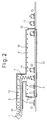
- Fig. 2 is a sectional view showing each of the apparatuses at the rear of a winder in a train of equipment to continuously manufacture steel wire according to the present invention.
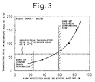
- Fig. 3 is a graph showing the relationship between the area reduction rate and the temperature rise in a rolling mill in the case where a 4-roll stand block mill employed in the present invention is used.
- Fig. 4 is a graph showing the relationship between residence time in an in-line heat treatment furnace employed in the present invention and the temperature of a steel wire coil.
- Fig. 5 is a block diagram of the case where a train of equipment composed of the temperature control apparatuses according to the present invention is incorporated in a steel wire manufacturing line.
- Fig. 6 is a general schematic view of an embodiment of the temperature control apparatuses for steel wire according to the present invention showing the case where heat retention covers are removed.
- Fig. 7 is a schematic view showing the embodiment shown in Fig. 7 in the case where the heat retention covers are in place.
- Fig. 8 is explanatory side views showing embodiments of No. 1 controlled cooling zone, which is a component of the equipment of the present invention.
- Fig. 9 is an explanatory view showing an example of pot type heat treatment furnaces employed in the present invention.
- the present inventors have accomplished this invention as a result of research and experiments aiming at inventing a train of steel wire manufacturing apparatuses having excellent productivity and practicability: capable of;
- Fig. 1 is a schematic view showing an example of a train of equipment to manufacture steel wire according to the present invention.
- reference numeral 1 is a pre-finishing block mill, which is, for example, a mill of a known type comprising 8 to 10 roll stands having a total area reduction rate of 85% or more.
- a reheating furnace to heat steel billets to be raw materials and roughing mill trains and intermediate mill trains to hot-roll the billets, heated to a prescribed temperature, into a desired size, are installed.
- the following reference numerals in the figure indicate the following apparatuses, respectively: 2 a finishing block mill to reduce the sectional area of steel wire to a final size, installed at the delivery side of said pre-finishing block mill 1; 3b a water cooling zone provided at the entry side of the finishing block mill 2; 3c another water cooling zone provided at the exit side of the finishing block mill 2; 4 a winder to wind the hot rolled steel wire into rings of a prescribed diameter using a laying head; 5 a controlled cooling conveyer to spread the wound steel wire into non-concentric rings and transport it; 6 a heat retention cover covering the wire transportation route of said controlled cooling conveyer 5; and 7 a bundling apparatus to let steel wire in rings 10 transferred on the conveyer fall vertically and to form a bundled coil around a bundling stem 9 waiting underneath.
- reference numeral 8 is an in-line heat treatment furnace one end of which is connected with the position of the bundling apparatus 7 and the other end of which extends in any chosen direction by any chosen length.
- Said heat treatment furnace 8 has a transfer conveyer 12 at its bottom for transporting, at a prescribed speed, and slow-cooling the steel wire coils 11 bundled and supported by the stems 9. Note that the interior of the heat treatment furnace 8 is transparently shown in the figure, different from the real appearance, for convenience sake.
- each of the water cooling zones 3b and 3c may consist of plural sections.
- Fig. 2 is a sectional view showing a specific example of structures of the controlled cooling conveyer 5, the bundling apparatus 7 and the in-line heat treatment furnace 8, each installed at the rear of the winder 4.
- the controlled cooling conveyer 5 to transfer the steel wire in rings 10 is covered over all its circumference with a heat-insulating heat retention cover 6 to prevent a temperature drop, during the stages after the rolling to the bundling, for the purpose of obtaining the maximum effect of the controlled rolling and, at the same time, to make the conveyer function as a holding conveyer to allow the slow cooling process to start from a prescribed temperature not below Ar 1 transformation point.
- the heat retention cover 6 is equipped, preferably, with heating apparatuses 13 such as radiant tubes or heaters to heat its interior as required for preventing temperature drop. Note that the controlled cooling conveyer 5 must have a length to secure a required holding time and that, if the temperature holding is not necessary, it can be omitted and the steel wire may be packed into bundled coils immediately after being wound.
- the bundling apparatus 7 provided at the rear end of the controlled cooling conveyer 5 is for receiving the wire rings falling from the conveyer in a manner that the stem 9 waiting underneath is inserted into the internal space of the rings to form a bundled coil of wire of a prescribed weight. It is desirable to form the bundled coils as tightly as possible to minimize temperature variance within a coil occurring during slow cooling. It is preferable to cover the bundling position, too, with heat-insulating walls continuously connected to the heat retention cover 6.
- the walls of the in-line heat treatment furnace 8 extending from the bundling position are also constructed of a continuous heat-insulating material.
- a door is provided at each end of said heat treatment furnace 8 (entry door 14 and exit door 15) for introducing the bundling stems 9 into the furnace and discharging them therefrom.
- Any suitable transfer means such as a roller conveyer or a chain conveyer may be selected as the conveyer 12 to transport the stems inside the heat treatment furnace 8.
- radiant tubes or any other suitable heating apparatuses 16 inside the heat treatment furnace 8 to prevent a temperature drop when necessary and to secure slow cooling at a very mild cooling rate of 0.1°C/sec. or slower in the furnace.
- Described hereafter are a preferable construction of the rolling mill, and preferable lengths of the water cooling and recuperation zones (especially the water cooling and recuperation zone at the entry side of the finishing block mill 2) and the in-line heat treatment furnace according to the present invention.
- the finishing block mill 2 consists of a block mill having at most 4 roll stands and its area reduction rate is in a range from 25 to 60%.
- Fig. 3 shows the relationship between the area reduction rate at finish rolling and the temperature rise in a finishing mill in the case of a 4-roll stand block mill. It can be understood from the figure that, assuming that an allowable temperature rise during finish rolling is 60°C, an appropriate range of area reduction rate is from 25 to 60%. The above figure for an allowable temperature rise was selected because the present inventors had confirmed, through studies, that the advantages of controlled rolling could be fully enjoyed when the material was cooled at a water cooling zone 3b, described hereafter, to a maximum extent but not to allow formation of an over-cooled structure and the temperature rise during finish rolling was controlled not to exceed 60°C.
- the strain imposed on the material is not enough to prevent uneven sectional strain distribution, which fact causes local growth of crystal grains and widely varied grain size, resulting in a phenomenon called coarse grains. This phenomenon markedly deteriorates cutting property and other aspects of workability.
- the area reduction rate exceeds 60%, on the other hand, temperature rise is rapidly accelerated by the rolling work, hindering the desired controlled rolling.
- the number of roll stands of the block mill is preferably 2, 3 or 4. Any number of roll stands not exceeding 4 may be chosen depending on the size of the steel wire to roll and other conditions.
- the water cooling zone 3b at the entry side of the finishing block mill 2 has a crucial function to maintain the material temperature at around 700°C, which is the entry temperature required for making the controlled rolling at the succeeding finishing block mill 2 effective.
- the zone between the mills including the water cooling zone 3b must have, besides the water cooling function, a recuperation function to homogenize the sectional temperature distribution created during the water cooling. It is important to specify the distance between the mills (denominated as d in Fig.1) for fulfilling this function.
- a very short time is enough for the water cooling, but the recuperation requires at least 0.1 sec. or so. Unless a time enough for the recuperation is secured, an excessive differential temperature will remain in the material section, resulting in an inhomogeneous material property created at the finish rolling.
- said distance has to be at least 1/10 of the distance traveled at the maximum rolling speed (exit speed from the finishing block mill) or longer.
- the maximum rolling speed is 100 m/sec.
- water cooling and a recuperation zone of at least 10 m long has to be provided.
- the speed at the entry of the finishing block mill is slower than the maximum rolling speed by a proportion corresponding to the area reduction rate of the finishing block mill, a little longer time than said 0.1 sec. necessary for the recuperation is secured and, hence, the water cooling process can be completed within the time thus secured.
- the length of the in-line heat treatment furnace 8 in other words, resident time of the steel wire coils in said furnace, to make the slow cooling after the controlled rolling effective.
- the resident time can be defined under the restriction of a standard target slow cooling rate of 0.1°C/sec. or slower.
- the coil interior portion is the portion cooled at a cooling rate slower than the target cooling rate even when left to cool naturally outside a furnace and, hence, a sufficiently slow cooling rate is achieved even if it is discharged from a furnace before completion of transformation.
- the present inventors discovered that, when a slow cooling operation proceeds under a furnace temperature set to cool the fastest cooled portion of the coil surface layer (A in Fig.4) at the target cooling rate of 0.1°C/sec., the slowest cooled portion of the surface layer (B in Fig.4) was cooled at a cooling rate of 0.07°C/sec., regardless of coil shape or wire diameter.
- the effect of slow cooling is saturated and no better result can be obtained if the resident time is prolonged to 1.0 hr. or longer: the furnace would simply be too long in such a case.
- the heat treatment furnace must have a capacity to accommodate 1/4 to all of the number of coils produced in 1 hr. at the maximum rolling capacity of the mill.
- Manufacturing steps are sequentially described hereafter based on the train of equipment to manufacture steel wire according to the present invention shown in Fig. 1.
- a billet of carbon steel or alloy steel is heated to 1,000°C or above in a reheating furnace, not shown in the figure, then it is rolled into a prescribed size by a roughing mill train and an intermediate mill train, and the rolled material is fed to a pre-finishing block mill 1 via a water cooling zone 3a.
- the material rolled by the pre-finishing block mill 1 at an area reduction rate of at least 85% is water-cooled and recuperated at another water cooling zone 3b, enters a finishing block mill 2 to be finish-rolled to a final product diameter at an area reduction rate of 25 to 60%, comes out from the mill at a finishing temperature of 750 to 800°C and, then, after passing through a third cooling zone 3c, is wound by a winder 4 into rings 10 of a prescribed diameter and laid onto a controlled/water cooling conveyer 5.
- the steel wire in rings is transferred in the shape of non-concentric circles while maintaining a temperature not below the Ar 1 transformation point. Then, reaching the bundling apparatus 7, it is left to fall around a bundling stem 9 to form a tightly bundled coil 11 of a prescribed weight, and the coil is slow-cooled while being transferred at a constant speed in an in-line heat treatment furnace 8.
- the stems, each loaded with a bundled steel wire coil, are transferred in the furnace, in order, at fixed intervals.
- the coil temperature at the commencement of the slow cooling is roughly 710 to 780°C.
- the steel wire in a coil is slow-cooled inside the heat treatment furnace at a cooling rate of 0.1°C/sec., then discharged through the furnace exit door roughly at 650°C to be left to cool naturally.
- the coiled wire completes the transformation during the natural cooling and is paid off for banding at a suitable position.
- the steel wire may be heated inside the heat retention cover 6 and/or the heat treatment furnace 8, using heating apparatuses, when its temperature drops.
- Fig.5 is a basic block diagram showing a series of manufacturing processes from rolling to conditioning and banding of the steel wire.
- the rolling equipment to heat the billets and hot roll them to a prescribed diameter and the winder to wind the rolled wire with a laying head into rings have already been described above.
- the temperature controlling apparatuses according to the present invention comprise, further:
- Fig. 6 is a general schematic view specifically showing main parts of the process equipment shown in Fig.1, wherein the heat retention covers of the conveyer lines after the winder are omitted and the in-line heat treatment furnace is shown transparently for convenience sake.
- Fig. 7 is, contrarily, a schematic view showing the heat retention covers and the heat treatment furnace as installed, and Fig. 8 is explanatory sectional side views of No. 1 controlled cooling zone after the winder and No. 1 bundling means.
- Fig. 6 the following reference numerals indicate the following apparatuses, respectively: 2 a high rigidity finishing block mill to reduce the sectional area of steel wire to a final diameter; 3c a water cooling zone provided at the exit side of the block mill 2; 4 a winder; 5 a blast and natural cooling conveyer to transfer steel wire 10 wound and spread in non-concentric rings by the winder 4; 17 an immersion cooling apparatus beneath the former part of said blast and natural cooling conveyer 5, virtually in parallel to the conveyer; 7-1 No. 1 bundling apparatus at the middle of the blast and natural cooling conveyer 5; 7-2 No. 2 bundling apparatus at the rear end of the blast and natural cooling conveyer 5; 18 a line switching conveyer at the position of No.
- 1 bundling apparatus 7-1 in a manner to allow switching to and from said No. 1 bundling apparatus 7-1; 8 a tunnel type in-line heat treatment furnace extending from the position of No. 1 bundling apparatus 7-1; 9 a bundling stem to be fed to the bundling apparatuses for receiving the wire rings; and 11 a bundled coil of steel wire being transferred in the in-line heat treatment furnace 8 by a transfer means such as a conveyer, after being bundled around a bundling stem 9.
- the blast and natural cooling conveyer 5 is installed from a position below the winder 4 to the position of No. 2 bundling apparatus 7-2 via No. 1 bundling apparatus 7-1 and the line switching conveyer 18.
- the former part and the latter part of the blast and natural cooling conveyer 5, divided at the position of No. 1 bundling apparatus 7-1, are covered over all their circumferences with respective heat retention covers 6a and 6b as shown in Fig.7.
- Said heat retention covers 6a and 6b are made of a heat insulation material and heat sources such as radiant tubes or heaters are provided inside them to heat their interiors as required for slow-cooling or heat retention of the steel wire in rings.
- a blast means not shown in the figure is provided somewhere beneath the blast and natural cooling conveyer 5 for cooling the wire rings with an air blast.
- the former part of the blast and natural cooling conveyer 5, from immediately after the winder to No. 1 bundling means, covered with a heat retention cover, and the immersion cooling apparatus 17 provided beneath it are collectively called No. 1 controlled cooling zone, and the latter part 19 of the blast and natural cooling conveyer 5, from immediately after No. 1 bundling means to No. 2 bundling means, covered with a heat retention cover, is called No. 2 controlled cooling zone (see Figs. 6 and 7).
- Fig. 8 (a) shows a case where the steel wire in rings 10 supplied from the winder 4 is led downward to the immersion cooling apparatus 17 for a rapid cooling, is packed into bundled coils at No. 1 bundling apparatus 7-1, and is fed to the heat treatment furnace 8 for a suitable heat treatment.
- line switching conveyers at the entry side of the blast and natural cooling conveyer 5 and at the position of No.1 bundling apparatus 7-1 are moved beforehand to their respective retracted positions (although Fig.
- FIG. 6 shows only one switching conveyer 18 at the position of No.1 bundling apparatus 7-1, actually there is a similar switching conveyer 20 also at the entry side of the blast and natural cooling conveyer 5).
- Any retraction method such as a vertical movement, as shown in the figure, a lateral movement or a swiveling movement is acceptable.
- the steel wire in rings 10 laid by the winder 4 is immediately immersed in an immersion tank 21 of the immersion cooling apparatus 17, transferred by a conveyer 22 in the tank, raised to the level of the blast and natural cooling conveyer 5, then falls around the bundling stem 9 at No. 1 bundling apparatus 7-1 to form a coil of a prescribed weight.
- a possible heat treatment is, for example, that the wire in rings 10 is quenched through rapid cooling in the immersion cooling apparatus 17 and then tempered in the heat treatment furnace 8 in the form of a coil.
- Either cold water or hot water may be used for the water cooling, allowing a choice in accordance with the steel grade and the required treatment pattern.
- Fig. 8 (b) shows a case where the switching conveyers 20 and 18 are set beforehand at the level of the blast and natural cooling conveyer 5 in order to transfer the wire in rings 10 directly to No. 2 bundling apparatus 7-2 for bundling into coils.
- the wire in rings 10 while being transferred on the conveyer 5, may be left to cool naturally, blast-cooled by blowing a chosen fluid onto the rings or, otherwise, slow-cooled or heat-retained by the heat retention covers 6a and 6b.
- the heat retention covers may be constructed so as to be capable of opening and closing.
- independent pot type furnaces 23 to cover the bundled steel wire coils 11 individually as shown in Fig. 9 may be used for slow-cooling or heating the coils in place of a tunnel type continuous furnace such as the in-line heat treatment furnace 8 shown in Figs. 6 and 7.
- the pot furnaces 23, each of which may be provided with internal heat sources, will be transported on a conveyer at a prescribed speed and at constant intervals.
Landscapes
- Engineering & Computer Science (AREA)
- Chemical & Material Sciences (AREA)
- Mechanical Engineering (AREA)
- Physics & Mathematics (AREA)
- Thermal Sciences (AREA)
- Crystallography & Structural Chemistry (AREA)
- Materials Engineering (AREA)
- Metallurgy (AREA)
- Organic Chemistry (AREA)
- Heat Treatment Of Strip Materials And Filament Materials (AREA)
- Metal Rolling (AREA)
- Winding, Rewinding, Material Storage Devices (AREA)
Abstract
Description
and not requiring a large scale modification of an existing steel wire rolling line.
Claims (13)
- A train of equipment to continuously manufacture steel wire characterized by sequentially connecting a hot rolling mill, to roll billets of carbon steel for machine structure use or alloy steel to a desired diameter, a winder to wind and form the rolled steel wire into rings, bundling apparatuses to pack the wire in rings into bundled coils and an in-line heat treatment furnace to slow-cool the wire packed into bundled coils, and by using a block mill having at most 4 roll stands as a final finishing mill of said hot rolling mill.
- A train of equipment to continuously manufacture steel wire, according to claim 1, characterized by controlling the area reduction rate of a block mill to within the range of 25 to 60%.
- A train of equipment to continuously manufacture steel wire, according to claim 1 or 2, characterized in that an in-line heat treatment furnace has a capacity to accommodate 1/4 to all of the number of bundled coils of wire rolled in 1 hr. at the maximum rolling capability.
- A train of equipment to continuously manufacture steel wire, according to any one of claims 1 to 3, characterized by installing, between a winder and bundling apparatuses, a controlled cooling and transporting apparatus equipped with heat retention covers to transfer steel wire formed into continuous non-concentric rings while holding it without lowering the temperature.
- A train of equipment to continuously manufacture steel wire, according to claim 4, characterized by winding steel wire using a winder at a temperature not below the Ar1 transformation point, transporting the wound wire without lowering the temperature below the Ar1 transformation point in a controlled cooling and transporting apparatus having heat retention covers and feeding the wire to bundling apparatuses.
- A train of equipment to continuously manufacture steel wire, according to any one of claims 1 to 5, characterized by installing, at the entry side of a final finishing mill, a water cooling and recuperation zone having a length equal to or longer than 1/10 of the distance traveled by steel wire in 1 sec. at the maximum rolling speed.
- A train of equipment to continuously manufacture steel wire, according to any one of claims 1 to 6, characterized by packing steel wire bundled in bundling apparatuses into tight coils by the use of stems inserted into the inner space of the coils and transporting the coils to a succeeding in-line heat treatment furnace.
- A train of equipment to continuously manufacture steel wire, according to claim 1, characterized: by installing;No. 1 controlled cooling zone easily and selectively convertible into any of a water cooling line, a blast cooling and natural cooling line and a slow cooling and heat retention line at the exit side of the winder to wind the hot-rolled steel wire into rings using a laying head,No. 2 controlled cooling zone easily and selectively convertible into any of a blast cooling and natural cooling line and a slow cooling and heat retention line, succeeding said No. 1 controlled cooling zone,a transfer means to transfer the steel wire in rings between the Nos. 1 and 2 controlled cooling zones and No. 1 bundling apparatus to pack the steel wire rings into bundled coils in a manner that each of them can be alternatively placed, at a boundary position between Nos. 1 and 2 controlled cooling zones,No. 2 bundling apparatus at the rear of said No. 2 controlled cooling zone, anda heat treatment means to slow-cool or heat the bundled coils of steel wire packed by said No. 1 bundling means connected to the position where said No. 1 bundling means is installed: andby selectively using the controlled cooling zones and/or the heat treatment means in accordance with the temperature pattern required for obtaining desired material properties of the steel wire.
- A train of equipment to continuously manufacture steel wire, according to claim 8, wherein a water cooling means of No. 1 controlled cooling zone has a cooling tank to directly immerse steel wire and a capability to use either cold water or hot water alternatively.
- A train of equipment to continuously manufacture steel wire, according to claim 8 or 9, wherein slow cooling means of Nos. 1 and 2 controlled cooling zones have heat retention covers or heat retention covers with heat sources.
- A train of equipment to continuously manufacture steel wire, according to any one of claims 8 to 10, wherein a heat treatment means for slow-cooling or heating the steel wire in bundled coils has a construction of a tunnel type to receive and transport steel wire packed into bundled coils or of a pot type to cover each of the coils.
- A train of equipment to continuously manufacture steel wire, according to any one of claims 8 to 11, characterized by continuously arranging temperature controlling apparatuses at the rear of a steel wire rolling line having, as a finishing rolling mill, a high rigidity block mill with a mill rigidity of at least 40 ton/mm or more.
- A train of equipment to continuously manufacture steel wire, according to claim 11, characterized by transporting and supplying steel wire coils coming from No. 2 bundling means and a heat treatment means to a common conditioning and banding means.
Applications Claiming Priority (5)
| Application Number | Priority Date | Filing Date | Title |
|---|---|---|---|
| JP14315699A JP3802707B2 (en) | 1999-05-24 | 1999-05-24 | Continuous production equipment line for wire |
| JP14315699 | 1999-05-24 | ||
| JP15228299A JP3686549B2 (en) | 1999-05-31 | 1999-05-31 | Hot rolled wire temperature control device |
| JP15228299 | 1999-05-31 | ||
| PCT/JP2000/003317 WO2000071274A1 (en) | 1999-05-24 | 2000-05-24 | Continuous production facilities for wire |
Publications (3)
| Publication Number | Publication Date |
|---|---|
| EP1125650A1 true EP1125650A1 (en) | 2001-08-22 |
| EP1125650A4 EP1125650A4 (en) | 2005-06-29 |
| EP1125650B1 EP1125650B1 (en) | 2007-07-18 |
Family
ID=26474950
Family Applications (1)
| Application Number | Title | Priority Date | Filing Date |
|---|---|---|---|
| EP00931542A Expired - Lifetime EP1125650B1 (en) | 1999-05-24 | 2000-05-24 | Continuous production facilities for wire |
Country Status (8)
| Country | Link |
|---|---|
| US (1) | US6634073B1 (en) |
| EP (1) | EP1125650B1 (en) |
| KR (1) | KR100408489B1 (en) |
| CN (1) | CN1156348C (en) |
| CA (1) | CA2338413C (en) |
| DE (1) | DE60035571T2 (en) |
| TW (1) | TW458819B (en) |
| WO (1) | WO2000071274A1 (en) |
Cited By (1)
| Publication number | Priority date | Publication date | Assignee | Title |
|---|---|---|---|---|
| EP1880777A1 (en) * | 2006-07-19 | 2008-01-23 | Morgan Construction Company | Method of transporting and heat treating coils of hot rolled products in a rolling mill |
Families Citing this family (20)
| Publication number | Priority date | Publication date | Assignee | Title |
|---|---|---|---|---|
| DE10103677B4 (en) * | 2001-01-27 | 2011-04-07 | Sms Siemag Aktiengesellschaft | Method for the production of wire ties low height |
| KR100544581B1 (en) * | 2001-12-21 | 2006-01-24 | 주식회사 포스코 | Cooling temperature adjusting device of hot rolled wire |
| US20050115646A1 (en) * | 2003-12-02 | 2005-06-02 | Accelerated Technologies Corporation | Stress free steel and rapid production of same |
| US8545645B2 (en) * | 2003-12-02 | 2013-10-01 | Franklin Leroy Stebbing | Stress free steel and rapid production of same |
| US7211687B2 (en) * | 2004-08-25 | 2007-05-01 | Unilever Home & Personal Care Usa | Process for making carboxyalkylates of branched alcohols |
| KR100815718B1 (en) | 2006-11-07 | 2008-03-20 | 주식회사 포스코 | Double layer heat treatment device of wire rod coil |
| KR100856295B1 (en) * | 2006-12-27 | 2008-09-03 | 주식회사 포스코 | Method of manufacturing flexible wire rods that can be omitted for heat treatment |
| KR101125958B1 (en) * | 2009-06-12 | 2012-03-21 | 주식회사 포스코 | Variable heat treatment apparatus and manufacturing method of high strength and high ductility wire rod using the same |
| US20110158767A1 (en) * | 2009-12-29 | 2011-06-30 | Ohio Rod Products | Reduced material, content fasteners and systems and methods for manufacturing the same |
| CN104308552B (en) * | 2014-09-28 | 2017-05-24 | 惠安县冠威机械设备有限公司 | System for producing condenser copper material |
| MX2017006869A (en) * | 2014-11-27 | 2017-08-14 | Jfe Steel Corp | EQUIPMENT LINE FOR MANUFACTURING PIPE AND STEEL PIPE WITHOUT SEWING AND METHOD FOR MANUFACTURING STAINLESS STEEL PIPE WITHOUT SEWING DUPLEX. |
| CN115328052B (en) * | 2022-08-23 | 2024-05-28 | 阳春新钢铁有限责任公司 | System and method for shortening double-channel period of high-line packing area |
| CN116371948A (en) * | 2023-02-07 | 2023-07-04 | 青岛雷霆重工股份有限公司 | A high-speed wire rod cooling method and its slow cooling line |
| CN116274436B (en) * | 2023-02-10 | 2025-08-29 | 马鞍山钢铁股份有限公司 | A method for eliminating extremely fine structure on the surface of GCr15 bearing steel bar |
| CN116716466A (en) * | 2023-05-24 | 2023-09-08 | 紫江炉业南京有限公司 | A kind of roller annealing furnace |
| CN116689479B (en) * | 2023-08-08 | 2023-12-26 | 中冶检测认证有限公司 | A process for producing vanadium-free low-silicon hot-rolled ribbed steel bars |
| CN117753777B (en) * | 2023-11-30 | 2026-06-19 | 常熟市龙腾特种钢有限公司 | Production method of ML40Cr hot rolled wire rod |
| CN118023286A (en) * | 2024-01-18 | 2024-05-14 | 天津市渤海大通冶金设备有限公司 | A method for rolling a bar by single wire after multi-wire slitting |
| TWI915008B (en) | 2024-10-09 | 2026-02-11 | 中國鋼鐵股份有限公司 | Insulation cover for Panyuan's cooling production line |
| CN119634468A (en) * | 2025-02-18 | 2025-03-18 | 常州机械刀片有限公司 | Alloy steel hot rolling mill and use method thereof |
Family Cites Families (15)
| Publication number | Priority date | Publication date | Assignee | Title |
|---|---|---|---|---|
| US3711918A (en) * | 1970-08-03 | 1973-01-23 | Morgan Construction Co | Split level conveyor and collecting means for controlled cooled steel rod |
| US4242153A (en) * | 1978-10-16 | 1980-12-30 | Morgan Construction Company | Methods for hot rolling and treating rod |
| US4546957A (en) * | 1982-11-22 | 1985-10-15 | Morgan Construction Company | Apparatus for combined hot rolling and treating steel rod |
| JPS6055572A (en) | 1983-09-05 | 1985-03-30 | Hitachi Ltd | Disk store case |
| NO166455C (en) * | 1984-09-07 | 1991-07-31 | Sumitomo Electric Industries | PROCEDURE AND DEVICE FOR DIRECT HEAT TREATMENT OF A STEEL STEEL WITH HIGH CARBON CONTENT. |
| JPS61257417A (en) | 1985-05-07 | 1986-11-14 | Sumitomo Metal Ind Ltd | Production of wire having excellent cold workability |
| JPH0437898Y2 (en) * | 1985-10-17 | 1992-09-04 | ||
| DE3830101A1 (en) * | 1988-09-05 | 1990-03-15 | Schloemann Siemag Ag | METHOD FOR OPERATING A STEEL ROLLING MILL WITH A REFRIGERATION LINE ARRANGED ON A ROLLING LINE FOR THERMOMECHANICAL FINISHED ROLLS AND ROLLING STEEL ROLLING MILL FOR IMPLEMENTING THE METHOD |
| IT1234063B (en) * | 1989-02-13 | 1992-04-27 | Danieli Off Mecc | MULTIFUNCTIONAL COOLING LINE. |
| JPH0437898A (en) | 1990-06-04 | 1992-02-07 | Mitsubishi Electric Corp | Stereoscopic character display device |
| CA2066475C (en) * | 1991-05-06 | 1997-06-03 | Terence M. Shore | Method and apparatus for continuously hot rolling of ferrous long products |
| JP2795588B2 (en) * | 1992-10-26 | 1998-09-10 | 住友重機械工業株式会社 | Rolling equipment for round bars and wires |
| JP3393677B2 (en) * | 1993-05-31 | 2003-04-07 | 新日本製鐵株式会社 | Direct heat treatment method for wire rod |
| JPH0798977A (en) | 1993-09-30 | 1995-04-11 | Nippon Conlux Co Ltd | Information recording / reproducing device |
| DE4436712A1 (en) | 1994-10-14 | 1996-04-18 | Schloemann Siemag Ag | Device for the heat treatment of steel wire |
-
2000
- 2000-05-23 TW TW089109930A patent/TW458819B/en not_active IP Right Cessation
- 2000-05-24 US US09/744,370 patent/US6634073B1/en not_active Expired - Lifetime
- 2000-05-24 CA CA002338413A patent/CA2338413C/en not_active Expired - Lifetime
- 2000-05-24 DE DE60035571T patent/DE60035571T2/en not_active Expired - Lifetime
- 2000-05-24 WO PCT/JP2000/003317 patent/WO2000071274A1/en not_active Ceased
- 2000-05-24 CN CNB008009953A patent/CN1156348C/en not_active Expired - Lifetime
- 2000-05-24 EP EP00931542A patent/EP1125650B1/en not_active Expired - Lifetime
- 2000-05-24 KR KR10-2001-7000870A patent/KR100408489B1/en not_active Expired - Fee Related
Cited By (1)
| Publication number | Priority date | Publication date | Assignee | Title |
|---|---|---|---|---|
| EP1880777A1 (en) * | 2006-07-19 | 2008-01-23 | Morgan Construction Company | Method of transporting and heat treating coils of hot rolled products in a rolling mill |
Also Published As
| Publication number | Publication date |
|---|---|
| US6634073B1 (en) | 2003-10-21 |
| CA2338413C (en) | 2005-06-21 |
| DE60035571T2 (en) | 2008-04-10 |
| DE60035571D1 (en) | 2007-08-30 |
| CN1156348C (en) | 2004-07-07 |
| KR100408489B1 (en) | 2003-12-06 |
| WO2000071274A1 (en) | 2000-11-30 |
| CA2338413A1 (en) | 2000-11-30 |
| KR20010053586A (en) | 2001-06-25 |
| EP1125650A4 (en) | 2005-06-29 |
| TW458819B (en) | 2001-10-11 |
| CN1310649A (en) | 2001-08-29 |
| EP1125650B1 (en) | 2007-07-18 |
Similar Documents
| Publication | Publication Date | Title |
|---|---|---|
| EP1125650B1 (en) | Continuous production facilities for wire | |
| US6783612B2 (en) | Method and apparatus for in-line heat treatment of hot rolled stock | |
| AU2008300996C1 (en) | Compact, flexible CSP facility for continuous, semi-continuous and batch operation | |
| RU2320431C2 (en) | Method for producing super-thin hot rolled strips of hot slabs and production line for performing the same | |
| KR100530925B1 (en) | Process and device for producing a ferritically rolled steel strip | |
| US5873960A (en) | Method and facility for manufacturing seamless steel pipe | |
| JPH09287028A (en) | Seamless steel pipe manufacturing method and manufacturing equipment | |
| KR970001550B1 (en) | Method and equipment for manufacturing hot rolled steel strip from continuous precast material | |
| US6289972B1 (en) | Integrated plant for the production of rolled stock | |
| US20020104597A1 (en) | Method and apparatus for producing steel | |
| JP3023030B2 (en) | Method and apparatus for producing rolled and coiled wires or round bars of carbon steel or special steel with various cross-sectional dimensions | |
| US5014412A (en) | Strip casting installation with rotary hearth furnace and method for producing hot-rolled steel strip therefrom | |
| US6240763B1 (en) | Automated rolling mill administration system | |
| US6264769B1 (en) | Coil area for in-line treatment of rolled products | |
| US4090697A (en) | Apparatus and method for treating wire | |
| JP3802707B2 (en) | Continuous production equipment line for wire | |
| EP0033194B1 (en) | Steel rod rolling process, and apparatus | |
| KR100507573B1 (en) | Method for cooling wire-rod with controlled rolling and apparatus for cooling the same | |
| KR101490600B1 (en) | Method for manufacturing wire rod | |
| JP3686549B2 (en) | Hot rolled wire temperature control device | |
| US5299783A (en) | Rod cooling apparatus | |
| US4491488A (en) | Steel rod rolling process | |
| Mitchell | Allied Steel and Wire-Six Months On | |
| JPS61257417A (en) | Production of wire having excellent cold workability |
Legal Events
| Date | Code | Title | Description |
|---|---|---|---|
| PUAI | Public reference made under article 153(3) epc to a published international application that has entered the european phase |
Free format text: ORIGINAL CODE: 0009012 |
|
| 17P | Request for examination filed |
Effective date: 20010221 |
|
| AK | Designated contracting states |
Kind code of ref document: A1 Designated state(s): AT BE CH CY DE DK ES FI FR GB GR IE IT LI LU MC NL PT SE |
|
| AX | Request for extension of the european patent |
Free format text: AL;LT;LV;MK;RO;SI |
|
| RBV | Designated contracting states (corrected) |
Designated state(s): DE FR GB IT |
|
| A4 | Supplementary search report drawn up and despatched |
Effective date: 20050513 |
|
| RIC1 | Information provided on ipc code assigned before grant |
Ipc: 7B 21C 47/26 B Ipc: 7B 21B 45/00 B Ipc: 7B 21B 43/00 A Ipc: 7C 21D 9/573 B |
|
| GRAP | Despatch of communication of intention to grant a patent |
Free format text: ORIGINAL CODE: EPIDOSNIGR1 |
|
| GRAS | Grant fee paid |
Free format text: ORIGINAL CODE: EPIDOSNIGR3 |
|
| GRAA | (expected) grant |
Free format text: ORIGINAL CODE: 0009210 |
|
| AK | Designated contracting states |
Kind code of ref document: B1 Designated state(s): DE FR GB IT |
|
| REG | Reference to a national code |
Ref country code: GB Ref legal event code: FG4D |
|
| REF | Corresponds to: |
Ref document number: 60035571 Country of ref document: DE Date of ref document: 20070830 Kind code of ref document: P |
|
| ET | Fr: translation filed | ||
| PLBE | No opposition filed within time limit |
Free format text: ORIGINAL CODE: 0009261 |
|
| STAA | Information on the status of an ep patent application or granted ep patent |
Free format text: STATUS: NO OPPOSITION FILED WITHIN TIME LIMIT |
|
| 26N | No opposition filed |
Effective date: 20080421 |
|
| REG | Reference to a national code |
Ref country code: DE Ref legal event code: R082 Ref document number: 60035571 Country of ref document: DE Representative=s name: VOSSIUS & PARTNER, DE Effective date: 20130227 Ref country code: DE Ref legal event code: R081 Ref document number: 60035571 Country of ref document: DE Owner name: NIPPON STEEL & SUMITOMO METAL CORPORATION, JP Free format text: FORMER OWNER: NIPPON STEEL CORP., TOKIO/TOKYO, JP Effective date: 20130227 Ref country code: DE Ref legal event code: R082 Ref document number: 60035571 Country of ref document: DE Representative=s name: VOSSIUS & PARTNER PATENTANWAELTE RECHTSANWAELT, DE Effective date: 20130227 |
|
| REG | Reference to a national code |
Ref country code: FR Ref legal event code: CD Owner name: NIPPON STEEL & SUMITOMO METAL CORPORATION, JP Effective date: 20130913 Ref country code: FR Ref legal event code: CA Effective date: 20130913 |
|
| REG | Reference to a national code |
Ref country code: FR Ref legal event code: PLFP Year of fee payment: 17 |
|
| REG | Reference to a national code |
Ref country code: FR Ref legal event code: PLFP Year of fee payment: 18 |
|
| REG | Reference to a national code |
Ref country code: FR Ref legal event code: PLFP Year of fee payment: 19 |
|
| REG | Reference to a national code |
Ref country code: DE Ref legal event code: R082 Ref document number: 60035571 Country of ref document: DE Representative=s name: VOSSIUS & PARTNER PATENTANWAELTE RECHTSANWAELT, DE Ref country code: DE Ref legal event code: R081 Ref document number: 60035571 Country of ref document: DE Owner name: NIPPON STEEL CORPORATION, JP Free format text: FORMER OWNER: NIPPON STEEL & SUMITOMO METAL CORPORATION, TOKYO, JP |
|
| PGFP | Annual fee paid to national office [announced via postgrant information from national office to epo] |
Ref country code: IT Payment date: 20190527 Year of fee payment: 20 Ref country code: DE Payment date: 20190514 Year of fee payment: 20 |
|
| PGFP | Annual fee paid to national office [announced via postgrant information from national office to epo] |
Ref country code: FR Payment date: 20190410 Year of fee payment: 20 |
|
| PGFP | Annual fee paid to national office [announced via postgrant information from national office to epo] |
Ref country code: GB Payment date: 20190522 Year of fee payment: 20 |
|
| REG | Reference to a national code |
Ref country code: DE Ref legal event code: R071 Ref document number: 60035571 Country of ref document: DE |
|
| REG | Reference to a national code |
Ref country code: GB Ref legal event code: PE20 Expiry date: 20200523 |
|
| PG25 | Lapsed in a contracting state [announced via postgrant information from national office to epo] |
Ref country code: GB Free format text: LAPSE BECAUSE OF EXPIRATION OF PROTECTION Effective date: 20200523 |