EP1125543A2 - Oral cavity washer with video scope - Google Patents
Oral cavity washer with video scope Download PDFInfo
- Publication number
- EP1125543A2 EP1125543A2 EP01101005A EP01101005A EP1125543A2 EP 1125543 A2 EP1125543 A2 EP 1125543A2 EP 01101005 A EP01101005 A EP 01101005A EP 01101005 A EP01101005 A EP 01101005A EP 1125543 A2 EP1125543 A2 EP 1125543A2
- Authority
- EP
- European Patent Office
- Prior art keywords
- video scope
- oral cavity
- grip portion
- image
- cavity washer
- Prior art date
- Legal status (The legal status is an assumption and is not a legal conclusion. Google has not performed a legal analysis and makes no representation as to the accuracy of the status listed.)
- Withdrawn
Links
Images
Classifications
-
- A—HUMAN NECESSITIES
- A61—MEDICAL OR VETERINARY SCIENCE; HYGIENE
- A61C—DENTISTRY; APPARATUS OR METHODS FOR ORAL OR DENTAL HYGIENE
- A61C17/00—Devices for cleaning, polishing, rinsing or drying teeth, teeth cavities or prostheses; Saliva removers; Dental appliances for receiving spittle
- A61C17/02—Rinsing or air-blowing devices, e.g. using fluid jets or comprising liquid medication
- A61C17/024—Rinsing or air-blowing devices, e.g. using fluid jets or comprising liquid medication with constant liquid flow
-
- A—HUMAN NECESSITIES
- A61—MEDICAL OR VETERINARY SCIENCE; HYGIENE
- A61B—DIAGNOSIS; SURGERY; IDENTIFICATION
- A61B1/00—Instruments for performing medical examinations of the interior of cavities or tubes of the body by visual or photographical inspection, e.g. endoscopes; Illuminating arrangements therefor
- A61B1/24—Instruments for performing medical examinations of the interior of cavities or tubes of the body by visual or photographical inspection, e.g. endoscopes; Illuminating arrangements therefor for the mouth, i.e. stomatoscopes, e.g. with tongue depressors; Instruments for opening or keeping open the mouth
-
- A—HUMAN NECESSITIES
- A61—MEDICAL OR VETERINARY SCIENCE; HYGIENE
- A61C—DENTISTRY; APPARATUS OR METHODS FOR ORAL OR DENTAL HYGIENE
- A61C17/00—Devices for cleaning, polishing, rinsing or drying teeth, teeth cavities or prostheses; Saliva removers; Dental appliances for receiving spittle
- A61C17/02—Rinsing or air-blowing devices, e.g. using fluid jets or comprising liquid medication
- A61C17/0202—Hand-pieces
-
- A—HUMAN NECESSITIES
- A61—MEDICAL OR VETERINARY SCIENCE; HYGIENE
- A61B—DIAGNOSIS; SURGERY; IDENTIFICATION
- A61B2560/00—Constructional details of operational features of apparatus; Accessories for medical measuring apparatus
- A61B2560/04—Constructional details of apparatus
- A61B2560/0456—Apparatus provided with a docking unit
Definitions
- the present invention relates to a video scope incorporating an image pick-up device such as a CCD for picking up an image of an interior of an oral cavity, and an oral cavity washer for washing the interior of the oral cavity by jetting fluid such as water onto teeth or gums.
- an image pick-up device such as a CCD for picking up an image of an interior of an oral cavity
- an oral cavity washer for washing the interior of the oral cavity by jetting fluid such as water onto teeth or gums.
- the video scope and the oral cavity washer have been separately used. More specifically, teeth or gums attached with leftovers and the like are observed by the video scope, and after those are removed by jetting water to those portions, it is necessary to confirm the result with the video scope. In this case, it is difficult to actually confirm on an image that a place which an operator observed with the video scope, and a place, to which water was jetted, coincide with each other.
- the present invention has been achieved in the light of the above described points, and an object of the present invention is to provide an oral cavity washer with a video scope capable of washing the interior of the oral cavity while actually confirming on an image that a place which the operator observes with the video scope and a place, to which fluid is jetted, coincide with each other.
- the 1 st invention of the present invention is an oral cavity washer with a video scope, comprising:
- a place where this liquid is jetted is confirmed on the image while jetting liquid, whereby not only washing, but also a massage effect the gums and the like by pressure of water, can also be expected. Therefore the practical utility is improved.
- the 2 nd invention of the present invention is the oral cavity washer with a video scope according to 1 st invention, wherein said display displays an aiming marker for indicating a reaching target point of said fluid jetted from said nozzle on an image picked up by said video scope.
- the 3 rd invention of the present invention is the oral cavity washer with a video scope according to 1 st or 2 nd inventions, further comprising a toothbrush portion having a brush portion and a third grip portion for being held by the operator, wherein said third grip portion and said first grip portion are capable of being made integral with each other.
- the 4 th invention of the present invention is the oral cavity washer with a video scope according to any of 1 st to 3rd inventions, further comprising illuminating meams of illuminating said object.
- the 5 th invention of the present invention is the oral cavity washer with a video scope according to any of 1 st to 4 th inventions, wherein said video scope has an optical window for transmitting light from said object, has further removal meams of removing any deposit on said optical window, and said image-forming means forms an image from light from said object which transmits said optical window.
- the 6 th invention of the present invention is the oral cavity washer with a video scope according to 5 th invention, wherein said removal means is jetting meams of jetting the fluid.
- the 7 th invention of the present invention is the oral cavity washer with a video scope according to 5 th or 6 th inventions , wherein the fluid is alternately jetted onto said object and said optical window.
- the 8 th invention of the present invention is the oral cavity washer with a video scope according to 6 th or 7 th inventions, wherein said nozzle serves as said jetting means .
- the 9 th invention of the present invention is the oral cavity washer with a video scope according to 7 th or 8 th inventions, wherein said nozzle causes said fluid to pulsate for jetting, and said fluid is alternately jetted to said object and said optical window in synchronism with the pulsation.
- the 10 th invention of the present invention is the oral cavity washer with a video scope according to any of 6 th to 9 th inventions, wherein a jetting velocity of the fluid to said optical window is controlled so as to be lower than a jetting velocity of the fluid to said object.
- the 11 th invention of the present invention is the oral cavity washer with a video scope according to 5 th invention, wherein said removal means is vibration meams of vibrating said optical window.
- the 12 th invention of the present invention is the oral cavity washer with a video scope according to any of 5 th to 11 th inventions, further comprising control means provided in said first grip portion, said second grip portion or said third grip portion, for controlling an operation of said removal means.
- the 13 th invention of the present invention is the oral cavity washer with a video scope according to any of 5 th to 12 th inventions, wherein said optical window is subjected to a water-repellent treatment, which secures transmission of visible light.
- the 14 th invention of the present invention is the oral cavity washer with a video scope according to 13 th invention, wherein said water-repellent treatment uses dimethyl silicone-based organic polymer water repellant or silane coupling agent having straight alkyl chain.
- the 15 th invention of the present invention is the oral cavity washer with a video scope according to any of 5 th to 12 th inventions, wherein said optical window is subjected to a hydrophilic treatment, which secures transmission of visible light.
- the 16 th invention of the present invention is the oral cavity washer with a video scope according to any of 1 st to 15 th inventions, wherein said display is provided on a charger for charging an apparatus installed in said first grip portion or said second grip portion, or on an installation apparatus on which said first grip portion is installed when the washer is not used.
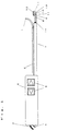
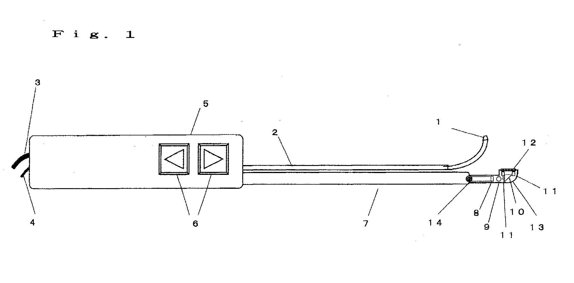
- FIG. 1 is a side view showing a portion of an oral cavity washer with a video scope according to a first embodiment of the present invention.
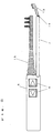
- FIG. 2 is a view showing that an oral cavity washer in the oral cavity washer with a video scope of FIG. 1 has been replaced with a toothbrush.
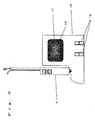
- FIG. 3 is an overall view showing an oral cavity washer with a video scope according to each embodiment of the present invention.
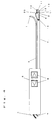
- FIG. 4 is a side view showing a portion of an oral cavity washer with a video scope according to the second to fifth embodiments of the present invention.
- FIG. 5 is a side view showing a portion of an oral cavity washer with a video scope according to a sixth embodiment of the present invention.
- the nozzle for jetting liquid to an object can be replaced with a toothbrush. These are replaced as required, whereby it becomes possible not only to perform washing for jetting liquid, but also to clean teeth by a toothbrush.
- the video scope can be utilized not only on jetting liquid, but also on cleaning teeth, which is effective.
- FIG. 1 is a side view showing a portion of an oral cavity washer with a video scope according to the present embodiment.
- reference numeral 1 denotes a nozzle for jetting liquid
- reference numeral 2 denotes a pipe for supplying liquid to be jetted to the nozzle 1 and fixing the nozzle 1 to a grip portion 5.
- Reference numeral 3 denotes a tube for supplying liquid to the nozzle 1 from the main body 16 shown in FIG. 3 through the grip portion 5 and the pipe 2.
- Reference numeral 4 denotes electric wire for supplying power supply to the grip portion 5 and the video scope and transmitting a signal from the video scope to the main body 16.
- this grip portion 5 there are incorporated: a power battery; a toothbrush driving motor; a signal processing circuit for a video scope; an image transmission circuit; various control circuits and the like. Also, this gripportion 5 is provided with a control switch 6 for controlling an operation of the video scope, and jetting of the liquid, and driving of an electric toothbrush. Further, this grip portion 5 is mounted with a video scope base 7 for supporting a head portion 13 of the video scope.
- Reference numeral 8 denotes a CCD unit in which a CCD, which is a solid state image pick-up device, is disposed at the tip end, and substrates for a driving circuit and a signal processing circuit are disposed at each terminal thereof.
- Reference numeral 9 denotes an objective lens, which forms an image on the light receiving surface of the CCD of the CCD unit 8.
- Reference numeral 10 denotes a prism mirror, to reflect pick-up light.
- An iris diaphragm is provided between the CCD unit 8 and the prism mirror 10 to adjust the angle of visibility, focal depth and the like, but is omitted in this drawing.
- the image-forming means is configured by the prism mirror 10, the iris diaphragm and the objective lens 9.
- Reference numeral 11 denotes a white LED for illuminating the object.
- Reference numeral 12 denotes an optical window consisting of glass or the like which performs a waterproof function by hermetically sealing from the outside, and transmits visible light such that light from the object is capable of being incident to the prism mirror 10.
- a image pick-up system is configured by these CCD unit 8 and image-forming means.
- a head portion 13 of the video scope is configured by this image pick-up system and the illumination means (white LED 11). This head portion 13 is mounted to a video scope base 7 through a hinge 14, and the head portion 13 is tilted to an adequate angle about the hinge 14.
- the video scope base 7 is fixed to the grip portion 5, and with in the video scope base 7, electric wiring for supplying various signals and electric power is provided, but is omitted in this figure.
- the main body 16 of FIG. 3 is provided with a tank for accumulating liquid to be jetted, and a pump for sending the liquid within this tank to the nozzle 1 through the tube 3, which are omitted in this figure.
- An image picked up by the video scope is displayed on a display 17 provided on the main body 16.
- the main body 16 has also a charging function. This is also utilized as an installation apparatus when not used. Further, there are installed an image receiving circuit for receiving an image which has been picked up by the video scope and has been transmitted and a display circuit. These provide ease of operation and space saving, enabling spread in homes and the like to be promoted.
- Each component of an oral cavity washer with a video scope according to the present embodiment is disposed as shown in FIG. 1, whereby it is possible to wash by jetting liquid while confirming an object tooth or gum on an image by using the video scope. Jetting of this liquid is controlled by a switch 6.
- the portion ahead of the pipe 2 and the video scope base 7 enters the oral cavity to observe the tooth or gum on a display 17, and to wash by jetting liquid.
- the angle of the head portion 13 and/or the position of an aiming marker 18 on the display 17 are adjusted in such a manner that a reaching target point of the liquid from the nozzle 1, that is, the object comes to the position of the aiming marker indicated by reference numeral 18 on the image of the display 17.
- an angle of visibility, a focal length and focal depth of the image-forming system, and an illumination angle and intensity of illumination means are adjusted in such a manner that the object can be clearly picked up to a suitable size.
- the washing can be more effectively performed.
- a switch 19 for adjusting the position of the aiming marker 18 and the jetting intensity is provided on the main body 16.
- FIG. 4 is a side view showing a portion of an oral cavity washer with a video scope according to a second embodiment of the present invention except for the display (display 17) .
- reference numerals 1 to 14 denote the same objects as those denoted by reference numerals 1 to 14 of FIG. 1, and have the same functions.
- Reference numeral 20 denotes a nozzle, which jets liquid such as water to the optical window 12. This liquid is sent from the main body 16 to the grip portion 5 through the tube 3, and is sent from the grip portion 5 to the nozzle 20 through the pipe housed in the video scope base 7. Jetting of liquid for washing this optical window 12 is controlled by a switch 6 provided at the grip portion 5 as described below.
- the switch 6 is operated to jet the liquid to the optical window 12 from the nozzle 20 for removing the adhered bubbles or water droplets.
- the control switch 6 can be operated to stop the jetting of the liquid from the nozzle 20.
- the optical window 12 is provided with the nozzle 20, which is means of jetting the liquid, and this nozzle 20 is controlled, whereby when bubbles or water droplets adhere to the optical window 12 to hinder the image pick-up during the washing operation while actually confirming on the image that a place which has been observed with the video scope coincides with a place, to which the liquid is j etted, those bubbles or water droplets can be removed. Thereby, it is possible to confirm with a stable image even during the washing operation, and the practical effect is very great.
- it may also be gas, not liquid, that is jetted from the nozzle 20. In short, it will suffice if only it is fluid.
- the switch 6 has been operated to jet the liquid to the optical window 12 from the nozzle 20 for removing the adhered bubbles or water droplets.
- the jetting velocity of the liquid from the nozzle 1 to the washing object is high among others, bubbles or water droplets may adhere to the optical window 12 in a moment by rebounding even after removal due to jetting of the liquid from the nozzle 20 to hinder the image pick-up.
- the nozzle 1 and the nozzle 20 automatically jet the liquid alternately.
- the liquid sent by a pump installed in the main body 16 is controlled by a change-over valve installed within the grip portion 5, whereby the liquid can be alternately jetted from the nozzle 1 and the nozzle 20.
- one pump is installed within the main body 16 as described above, it is possible to remove any bubbles or water droplets on the optical window 12 without reducing an amount of jet from the nozzle 1 and the velocity by alternately jetting.
- the nozzle 20 which is the meams of jetting the liquid to the optical window 12, and the nozzle 1, which jets the liquid to the washing object, alternately jet the liquid, whereby the amount of jet from the nozzle 1 and the velocity are not reduced even in the case of one pump, but the practical effect is very great.
- the liquid on jetting the liquid from the nozzle 1 for washing, the liquid is caused to pulsate.
- the amount of jetting and/or the velocity of the liquid from the nozzle 1 are caused to change, for example, periodically.
- the instantaneous maximum amount of jetting and velocity are caused to increase for improving the washing effect and exhibiting a massage effect.
- Such a pulsation is synchronized with switching timing when the nozzle 1 and the nozzle 20 automatically jet the liquid alternately.
- the present embodiment is advantageous in the practical use because it is prone to be used together with the conventional pulsating operation.
- the pulsating frequency is set at about 20 Hz or higher, a visual perception degree for the alternate jetting to this washing object and the optical window 12 is decreased, and therefore, continuous observation can be performed without any discomfort.
- jetting to the washing object is caused to pulsate, and this jetting is caused to synchronize with the switching timing between the nozzle 1 and the nozzle 20, whereby bubbles and water droplets on the optical window 12 can be removed without reducing the amount of jetting from the nozzle 1 and the velocity even in the case of one pump.
- the configuration of the mechanism is advantageous in the practical use. Also, continuous observation can be performed without any discomfort, and the practical effect is quite great.
- the nozzle 1 and the nozzle 20 automatically jet the liquid alternately as shown in the third and fourth embodiments, but it is characterized in that the amount of jetting from the nozzle 20 for jetting to the optical window 12 and the velocity are caused to be reduced lower than the nozzle 1.
- a flow rate and flow velocity required to remove bubbles or water droplets may be sufficiently lower than a flow rate and flow velocity required to wash. Therefore, particularly in the case of one pump, the amount of jetting from the nozzle 20 and velocity are reduced, whereby the amount of jetting from the nozzle 1 and the velocity can be increased as a result. In other words, the amount of jetting from the nozzle 20 and the velocity are limited, whereby the jetting capacity can be accumulated during a period of time for jetting from the nozzle 20.
- the nozzle 20 which is meams of jetting the liquid
- the nozzle 1 which jets the liquid to the washing object, alternately jet the liquid to the optical window 12 to reduce the amount of jetting from the nozzle 20 and the velocity, whereby even in the case of one pump, the amount of jetting from the nozzle 1 and the velocity can be sufficiently secured, and the practical effect is very great.
- the nozzle 20 for removing deposit onto the optical window 12 has been separately provided from the nozzle 1, but it may be possible to cause the nozzle 1 to have the function of the nozzle 20, and not to provide the nozzle 20.
- FIG. 5 is a side view showing a portion of an oral cavity washer with a video scope according to a sixth embodiment of the present invention except for a display (display 17).
- Reference numerals 3,4 and 7 to 14 of FIG. 5 denote the same components as those denoted by reference numerals 3,4 and 7 to 14 of FIG. 1 disposed similarly.
- Reference numeral 21 denotes a nozzle for jetting the liquid to the object, which jets the liquid supplied from the main body through a pipe installed within a video scope base 7, a grip portion 23 and a tube 3.
- Reference numeral 23 denotes a grip portion
- reference numeral 24 denotes a control switch provided in the grip portion 23, for controlling jetting and the like.
- the grip portion 23 shown in the present embodiment cannot be provided with a toothbrush , but can be made that much smaller than the grip portion 5, and has improved ease of operation.
- reference numeral 22 denotes a piezo-electric vibrator made of, for example, barium titanate porcelain, which micro-vibrates the optical window 12 at a frequency of, for example, 28 KHz. The operation of this piezo-electric vibrator 22 is controlled by the control switch 24.
- the switch 24 When bubbles or water droplets, which have occurred during a washing operation, adhere to the optical window 12 to hinder the image pick-up, the switch 24 is operated to micro-vibrate the piezo-electric vibrator 22 to remove the bubbles or water droplets adhered to the optical window 12. At a point of time whereat the removal can be confirmed by the pick-up image or the like, the control switch 24 is operated to stop the micro-vibration.
- the piezo-electric vibrator 22 has been made of barium titanate porcelain, but the material for the piezo-electric vibrator 22 is not limited to the barium titanate porcelain. In short, the piezo-electric vibrator 22 may be made of any material so long as it vibrates the optical window 12. Also, the piezo-electric vibrator 22 has vibrated the optical window 12 at a frequency of, for example, 28 KHz, but the vibration frequency is not limited to 28 KHz.
- the present embodiment is configured as shown in FIG. 5 as in the sixth embodiment, but the optical window 12 has been subjected to the water-repellent treatment.
- the outside surface of the optical window 12 is made water-repellent using a silane coupling agent having straight alkyl chain represented by CF 3 (CF 2 ) n (CH 2 ) 2 SiCl 3 (where n is 0 or an integer of 1 or higher) or the like .
- the film thickness of this water-repellent treatment is 10 nm or less, and actually transmits visible light completely.
- the switch 24 When bubbles or water droplets, which have occurred during a washing operation, adhere to the optical window 12 to hinder the image pick-up, the switch 24 is operated to micro-vibrate the piezo-electric vibrator 22 to remove the bubbles or water droplets adhered to the optical window 12. At a point of time whereat the removal can be confirmed by the pick-up image or the like , the control switch 24 is operated to stop the micro-vibration. At this time, since the optical window 12 has been subj ected to the water-repellent treatment, it is easy to remove the bubbles or water droplets.
- dimethyl silicone-based organic polymer water repellant is capable of obtaining an effect that it is made easier to remove deposit such as bubbles if only transmission of visible light is secured.
- the optical window 12 in FIGS . 1, 2, 4 and 5 has been subjected to a hydrophilic treatment.
- the nozzle 1 or the nozzle 21 has only to wash the object such as the teeth or gums by jetting fluid.
- the display 17 may be mounted by embedding it in a portion of a mirror in a toilet room among others, or may be mounted onto the user's head.
- an oral cavity washer with a video scope capable of washing the interior of the oral cavity while actually confirming on the image that a place which the operator has observed with the video scope coincides with a place, to which the fluid is jetted.
Landscapes
- Health & Medical Sciences (AREA)
- Life Sciences & Earth Sciences (AREA)
- Surgery (AREA)
- Dentistry (AREA)
- Animal Behavior & Ethology (AREA)
- General Health & Medical Sciences (AREA)
- Public Health (AREA)
- Veterinary Medicine (AREA)
- Optics & Photonics (AREA)
- Biomedical Technology (AREA)
- Biophysics (AREA)
- Nuclear Medicine, Radiotherapy & Molecular Imaging (AREA)
- Oral & Maxillofacial Surgery (AREA)
- Pathology (AREA)
- Radiology & Medical Imaging (AREA)
- Molecular Biology (AREA)
- Engineering & Computer Science (AREA)
- Physics & Mathematics (AREA)
- Heart & Thoracic Surgery (AREA)
- Medical Informatics (AREA)
- Epidemiology (AREA)
- Brushes (AREA)
- Endoscopes (AREA)
- Dental Tools And Instruments Or Auxiliary Dental Instruments (AREA)
- Closed-Circuit Television Systems (AREA)
- Instruments For Viewing The Inside Of Hollow Bodies (AREA)
Abstract
Description
- The present invention relates to a video scope incorporating an image pick-up device such as a CCD for picking up an image of an interior of an oral cavity, and an oral cavity washer for washing the interior of the oral cavity by jetting fluid such as water onto teeth or gums.
- In recent years, a video scope using a CCD capable of picking up an image of a limited part while illuminating has been used for medical examination for a diseased part within the oral cavity in density, oral surgery and the like, and further for an operator to observe conditions of his own teeth or gums. In addition, in homes, there have become popular oral cavity washers for jetting water onto the teeth or gums with the aim of washing the interior of the oral cavity.
- For a video scope for performing such local image pick-up and a nozzle portion for jetting liquid of the oral cavity washer, there is required one easy to handle, capable of being operated by holding by one hand.
- Conventionally, the video scope and the oral cavity washer have been separately used. More specifically, teeth or gums attached with leftovers and the like are observed by the video scope, and after those are removed by jetting water to those portions, it is necessary to confirm the result with the video scope. In this case, it is difficult to actually confirm on an image that a place which an operator observed with the video scope, and a place, to which water was jetted, coincide with each other.
- Also, since oral cavity washing is usually performed within a limited space such as a lavatory, it is often difficult in ordinary households to newly secure space to install a display for displaying a video scope image.
- Further, in order to observe or wash all the teeth or gums thoroughly, complicated operations, such as shifting the video scope or the nozzle from one hand to the other or rotation, is necessary, and therefore, it is desirable to make it cordless.
- The present invention has been achieved in the light of the above described points, and an object of the present invention is to provide an oral cavity washer with a video scope capable of washing the interior of the oral cavity while actually confirming on an image that a place which the operator observes with the video scope and a place, to which fluid is jetted, coincide with each other.
- The 1st invention of the present invention is an oral cavity washer with a video scope, comprising:
- a video scope having image-forming means of forming an image from light from an object, an image pick-up device for converting the light from which the image is formed by said image-forming means into an electric signal, and a first grip portion for being held by an operator;
- a display for displaying an image picked up by said video scope; and
- an oral cavity washer having a nozzle for jetting a fluid and a second grip portion for being held by the operator, for washing an oral cavity by jetting said fluid to teeth or gums,
- wherein said first grip portion and said second grip portion are capable of being made integral with each other.
-
- A place where a liquid jetted for washing collides with an object, that is, teeth or gums, is located within the image pick-up range of the video scope, so that a washing operation can be performed while confirming a place to be washed on an image. In this manner, a place where this liquid is jetted is confirmed on the image while jetting liquid, whereby not only washing, but also a massage effect the gums and the like by pressure of water, can also be expected. Therefore the practical utility is improved.
- The 2nd invention of the present invention is the oral cavity washer with a video scope according to 1st invention, wherein said display displays an aiming marker for indicating a reaching target point of said fluid jetted from said nozzle on an image picked up by said video scope.
- The 3rd invention of the present invention is the oral cavity washer with a video scope according to 1st or 2nd inventions, further comprising a toothbrush portion having a brush portion and a third grip portion for being held by the operator, wherein said third grip portion and said first grip portion are capable of being made integral with each other.
- The 4th invention of the present invention is the oral cavity washer with a video scope according to any of 1st to 3rd inventions, further comprising illuminating meams of illuminating said object.
- The 5th invention of the present invention is the oral cavity washer with a video scope according to any of 1st to 4th inventions, wherein said video scope has an optical window for transmitting light from said object, has further removal meams of removing any deposit on said optical window, and said image-forming means forms an image from light from said object which transmits said optical window.
- The 6th invention of the present invention is the oral cavity washer with a video scope according to 5th invention, wherein said removal means is jetting meams of jetting the fluid.
- The 7th invention of the present invention is the oral cavity washer with a video scope according to 5th or 6th inventions , wherein the fluid is alternately jetted onto said object and said optical window.
- The 8th invention of the present invention is the oral cavity washer with a video scope according to 6th or 7th inventions, wherein said nozzle serves as said jetting means .
- The 9th invention of the present invention is the oral cavity washer with a video scope according to 7th or 8th inventions, wherein said nozzle causes said fluid to pulsate for jetting, and said fluid is alternately jetted to said object and said optical window in synchronism with the pulsation.
- The 10th invention of the present invention is the oral cavity washer with a video scope according to any of 6th to 9th inventions, wherein a jetting velocity of the fluid to said optical window is controlled so as to be lower than a jetting velocity of the fluid to said object.
- The 11th invention of the present invention is the oral cavity washer with a video scope according to 5th invention, wherein said removal means is vibration meams of vibrating said optical window.
- The 12th invention of the present invention is the oral cavity washer with a video scope according to any of 5th to 11th inventions, further comprising control means provided in said first grip portion, said second grip portion or said third grip portion, for controlling an operation of said removal means.
- The 13th invention of the present invention is the oral cavity washer with a video scope according to any of 5th to 12th inventions, wherein said optical window is subjected to a water-repellent treatment, which secures transmission of visible light.
- The 14th invention of the present invention is the oral cavity washer with a video scope according to 13th invention, wherein said water-repellent treatment uses dimethyl silicone-based organic polymer water repellant or silane coupling agent having straight alkyl chain.
- The 15th invention of the present invention is the oral cavity washer with a video scope according to any of 5th to 12th inventions, wherein said optical window is subjected to a hydrophilic treatment, which secures transmission of visible light.
- The 16th invention of the present invention is the oral cavity washer with a video scope according to any of 1st to 15th inventions, wherein said display is provided on a charger for charging an apparatus installed in said first grip portion or said second grip portion, or on an installation apparatus on which said first grip portion is installed when the washer is not used.
- FIG. 1 is a side view showing a portion of an oral cavity washer with a video scope according to a first embodiment of the present invention.
- FIG. 2 is a view showing that an oral cavity washer in the oral cavity washer with a video scope of FIG. 1 has been replaced with a toothbrush.
- FIG. 3 is an overall view showing an oral cavity washer with a video scope according to each embodiment of the present invention.
- FIG. 4 is a side view showing a portion of an oral cavity washer with a video scope according to the second to fifth embodiments of the present invention.
- FIG. 5 is a side view showing a portion of an oral cavity washer with a video scope according to a sixth embodiment of the present invention.
-
- 1
- NOZZLE
- 2
- PIPE
- 3
- TUBE
- 4
- ELECTRIC WIRE
- 5
- GRIP PORTION
- 6
- CONTROL SWITCH
- 7
- VIDEO SCOPE BASE
- 8
- CCD UNIT
- 9
- OBJECTIVE LENS
- 10
- PRISM MIRROR
- 11
- WHITE LED
- 12
- OPTICAL WINDOW
- 13
- HEAD PORTION OF VIDEO SCOPE
- 14
- HINGE
- Hereinafter with reference to the drawings, embodiments of the present invention will be described.
- Hereinafter, with reference to FIGS. 1 to 3, the description will be made of an embodiment of the present invention.
- In the present embodiment, the nozzle for jetting liquid to an object can be replaced with a toothbrush. These are replaced as required, whereby it becomes possible not only to perform washing for jetting liquid, but also to clean teeth by a toothbrush. By having this replacement function, the video scope can be utilized not only on jetting liquid, but also on cleaning teeth, which is effective.
- FIG. 1 is a side view showing a portion of an oral cavity washer with a video scope according to the present embodiment. In FIG. 1,
reference numeral 1 denotes a nozzle for jetting liquid, andreference numeral 2 denotes a pipe for supplying liquid to be jetted to thenozzle 1 and fixing thenozzle 1 to agrip portion 5.Reference numeral 3 denotes a tube for supplying liquid to thenozzle 1 from themain body 16 shown in FIG. 3 through thegrip portion 5 and thepipe 2.Reference numeral 4 denotes electric wire for supplying power supply to thegrip portion 5 and the video scope and transmitting a signal from the video scope to themain body 16. - In the
grip portion 5, there are incorporated: a power battery; a toothbrush driving motor; a signal processing circuit for a video scope; an image transmission circuit; various control circuits and the like. Also, thisgripportion 5 is provided with acontrol switch 6 for controlling an operation of the video scope, and jetting of the liquid, and driving of an electric toothbrush. Further, thisgrip portion 5 is mounted with avideo scope base 7 for supporting a head portion 13 of the video scope. - Reference numeral 8 denotes a CCD unit in which a CCD, which is a solid state image pick-up device, is disposed at the tip end, and substrates for a driving circuit and a signal processing circuit are disposed at each terminal thereof. Reference numeral 9 denotes an objective lens, which forms an image on the light receiving surface of the CCD of the CCD unit 8.
Reference numeral 10 denotes a prism mirror, to reflect pick-up light. An iris diaphragm is provided between the CCD unit 8 and theprism mirror 10 to adjust the angle of visibility, focal depth and the like, but is omitted in this drawing. The image-forming means is configured by theprism mirror 10, the iris diaphragm and the objective lens 9. - Reference numeral 11 denotes a white LED for illuminating the object. Reference numeral 12 denotes an optical window consisting of glass or the like which performs a waterproof function by hermetically sealing from the outside, and transmits visible light such that light from the object is capable of being incident to the
prism mirror 10. A image pick-up system is configured by these CCD unit 8 and image-forming means. A head portion 13 of the video scope is configured by this image pick-up system and the illumination means (white LED 11). This head portion 13 is mounted to avideo scope base 7 through ahinge 14, and the head portion 13 is tilted to an adequate angle about thehinge 14. - The
video scope base 7 is fixed to thegrip portion 5, and with in thevideo scope base 7, electric wiring for supplying various signals and electric power is provided, but is omitted in this figure. - The
main body 16 of FIG. 3 is provided with a tank for accumulating liquid to be jetted, and a pump for sending the liquid within this tank to thenozzle 1 through thetube 3, which are omitted in this figure. An image picked up by the video scope is displayed on adisplay 17 provided on themain body 16. Themain body 16 has also a charging function. This is also utilized as an installation apparatus when not used. Further, there are installed an image receiving circuit for receiving an image which has been picked up by the video scope and has been transmitted and a display circuit. These provide ease of operation and space saving, enabling spread in homes and the like to be promoted. - Each component of an oral cavity washer with a video scope according to the present embodiment is disposed as shown in FIG. 1, whereby it is possible to wash by jetting liquid while confirming an object tooth or gum on an image by using the video scope. Jetting of this liquid is controlled by a
switch 6. - The portion ahead of the
pipe 2 and thevideo scope base 7 enters the oral cavity to observe the tooth or gum on adisplay 17, and to wash by jetting liquid. In this washing, when thenozzle 1 and the object are located at a suitable distance, the angle of the head portion 13 and/or the position of an aimingmarker 18 on thedisplay 17 are adjusted in such a manner that a reaching target point of the liquid from thenozzle 1, that is, the object comes to the position of the aiming marker indicated byreference numeral 18 on the image of thedisplay 17. - With this adjustment, an angle of visibility, a focal length and focal depth of the image-forming system, and an illumination angle and intensity of illumination means are adjusted in such a manner that the object can be clearly picked up to a suitable size. By displaying the aiming
marker 18 on the image of thedisplay 17 in this manner, the washing can be more effectively performed. On themain body 16, there is provided aswitch 19 for adjusting the position of the aimingmarker 18 and the jetting intensity. In this respect, when such an object as, for example, a specific tooth is clearly displayed on thedisplay 17 and the object comes to the position of the aimingmarker 18, it is structured such that the liquid from thenozzle 1 reaches the object. - When the
nozzle 1 and thepipe 2 are removed from thegrip portion 5 and thetoothbrush 15 is installed to the toothbrush base of thegrip portion 5 as shown in FIG. 2, it is also possible to clean the teeth by using the toothbrush. In this case, it is also possible to use by removing thetube 3. At this time, when the angle of the head portion 13 is adjusted such that the tip end portion of the brush comes within the image-forming range, it can be more easily used. Further, if the video scope is driven by the power supply within thegrip portion 5 and the image is transmitted to themain body 16 through electromagnetic wave or the like, it will be able to be used by removing theelectric wire 4. By making it cordless in this manner, the usability will be further improved. - As described above, it is possible to wash while actually confirming on the image that a place which has been observed with the video scope coincides with a place, to which the liquid is jetted, and the practical effect is very significant. Further, it is also possible to clean the teeth as required, which is effective.
- In this respect, in the present embodiment, there has been shown an example in which the
nozzle 1 and thepipe 2 have been removed on mounting thetoothbrush 15, but it is not always necessary to do so. However, if thetoothbrush 15, thenozzle 1 and thepipe 2 are arranged so as to be able to be mounted to the video scope at the same time, thegrip portion 5 and the like will become larger in size. - FIG. 4 is a side view showing a portion of an oral cavity washer with a video scope according to a second embodiment of the present invention except for the display (display 17) . In FIG. 4,
reference numerals 1 to 14 denote the same objects as those denoted byreference numerals 1 to 14 of FIG. 1, and have the same functions.Reference numeral 20 denotes a nozzle, which jets liquid such as water to the optical window 12. This liquid is sent from themain body 16 to thegrip portion 5 through thetube 3, and is sent from thegrip portion 5 to thenozzle 20 through the pipe housed in thevideo scope base 7. Jetting of liquid for washing this optical window 12 is controlled by aswitch 6 provided at thegrip portion 5 as described below. - During the washing operation for the object using liquid from the
nozzle 1, bubbles or water droplets are prone to occur, and these bubbles or water droplets may adhere to the optical window 12 to hinder the image pick-up. At this time, theswitch 6 is operated to jet the liquid to the optical window 12 from thenozzle 20 for removing the adhered bubbles or water droplets. At a point of time whereat this removal can be confirmed by an image picked up, thecontrol switch 6 can be operated to stop the jetting of the liquid from thenozzle 20. - As described above, the optical window 12 is provided with the
nozzle 20, which is means of jetting the liquid, and thisnozzle 20 is controlled, whereby when bubbles or water droplets adhere to the optical window 12 to hinder the image pick-up during the washing operation while actually confirming on the image that a place which has been observed with the video scope coincides with a place, to which the liquid is j etted, those bubbles or water droplets can be removed. Thereby, it is possible to confirm with a stable image even during the washing operation, and the practical effect is very great. - In this respect, it may also be gas, not liquid, that is jetted from the
nozzle 20. In short, it will suffice if only it is fluid. - With reference to FIG. 4, the description will be made of a third embodiment according to the present invention.
- In the second embodiment, when bubbles or water droplets adhere to the optical window 12 to hinder the image pick-up during the washing operation, the
switch 6 has been operated to jet the liquid to the optical window 12 from thenozzle 20 for removing the adhered bubbles or water droplets. At this time, when the jetting velocity of the liquid from thenozzle 1 to the washing object is high among others, bubbles or water droplets may adhere to the optical window 12 in a moment by rebounding even after removal due to jetting of the liquid from thenozzle 20 to hinder the image pick-up. - In order to cope with such a case, according to the present embodiment, the
nozzle 1 and thenozzle 20 automatically jet the liquid alternately. The liquid sent by a pump installed in themain body 16 is controlled by a change-over valve installed within thegrip portion 5, whereby the liquid can be alternately jetted from thenozzle 1 and thenozzle 20. In the case where one pump is installed within themain body 16 as described above, it is possible to remove any bubbles or water droplets on the optical window 12 without reducing an amount of jet from thenozzle 1 and the velocity by alternately jetting. - As described above, the
nozzle 20, which is the meams of jetting the liquid to the optical window 12, and thenozzle 1, which jets the liquid to the washing object, alternately jet the liquid, whereby the amount of jet from thenozzle 1 and the velocity are not reduced even in the case of one pump, but the practical effect is very great. - With reference to FIG. 4, the description will be made of a fourth embodiment according to the present invention.
- In the present embodiment, on jetting the liquid from the
nozzle 1 for washing, the liquid is caused to pulsate. In other words, the amount of jetting and/or the velocity of the liquid from thenozzle 1 are caused to change, for example, periodically. As described above, the instantaneous maximum amount of jetting and velocity are caused to increase for improving the washing effect and exhibiting a massage effect. Such a pulsation is synchronized with switching timing when thenozzle 1 and thenozzle 20 automatically jet the liquid alternately. Thereby, as in the third embodiment, even in the case of one pump, bubbles or water droplets on the optical window 12 can be removed without reducing the jet velocity of thenozzle 1. Further, the present embodiment is advantageous in the practical use because it is prone to be used together with the conventional pulsating operation. - Also, when the pulsating frequency is set at about 20 Hz or higher, a visual perception degree for the alternate jetting to this washing object and the optical window 12 is decreased, and therefore, continuous observation can be performed without any discomfort.
- As described above, jetting to the washing object is caused to pulsate, and this jetting is caused to synchronize with the switching timing between the
nozzle 1 and thenozzle 20, whereby bubbles and water droplets on the optical window 12 can be removed without reducing the amount of jetting from thenozzle 1 and the velocity even in the case of one pump. Further, the configuration of the mechanism is advantageous in the practical use. Also, continuous observation can be performed without any discomfort, and the practical effect is quite great. - With reference to FIG. 4, the description will be made of a fifth embodiment according to the present invention.
- In the present embodiment, the
nozzle 1 and thenozzle 20 automatically jet the liquid alternately as shown in the third and fourth embodiments, but it is characterized in that the amount of jetting from thenozzle 20 for jetting to the optical window 12 and the velocity are caused to be reduced lower than thenozzle 1. - A flow rate and flow velocity required to remove bubbles or water droplets may be sufficiently lower than a flow rate and flow velocity required to wash. Therefore, particularly in the case of one pump, the amount of jetting from the
nozzle 20 and velocity are reduced, whereby the amount of jetting from thenozzle 1 and the velocity can be increased as a result. In other words, the amount of jetting from thenozzle 20 and the velocity are limited, whereby the jetting capacity can be accumulated during a period of time for jetting from thenozzle 20. - As described above, the
nozzle 20, which is meams of jetting the liquid, and thenozzle 1, which jets the liquid to the washing object, alternately jet the liquid to the optical window 12 to reduce the amount of jetting from thenozzle 20 and the velocity, whereby even in the case of one pump, the amount of jetting from thenozzle 1 and the velocity can be sufficiently secured, and the practical effect is very great. - In this respect, in the above described second to fifth embodiments, the
nozzle 20 for removing deposit onto the optical window 12 has been separately provided from thenozzle 1, but it may be possible to cause thenozzle 1 to have the function of thenozzle 20, and not to provide thenozzle 20. - FIG. 5 is a side view showing a portion of an oral cavity washer with a video scope according to a sixth embodiment of the present invention except for a display (display 17).
Reference numerals reference numerals -
Reference numeral 21 denotes a nozzle for jetting the liquid to the object, which jets the liquid supplied from the main body through a pipe installed within avideo scope base 7, agrip portion 23 and atube 3.Reference numeral 23 denotes a grip portion, andreference numeral 24 denotes a control switch provided in thegrip portion 23, for controlling jetting and the like. Thegrip portion 23 shown in the present embodiment cannot be provided with a toothbrush , but can be made that much smaller than thegrip portion 5, and has improved ease of operation. In FIG. 5,reference numeral 22 denotes a piezo-electric vibrator made of, for example, barium titanate porcelain, which micro-vibrates the optical window 12 at a frequency of, for example, 28 KHz. The operation of this piezo-electric vibrator 22 is controlled by thecontrol switch 24. - When bubbles or water droplets, which have occurred during a washing operation, adhere to the optical window 12 to hinder the image pick-up, the
switch 24 is operated to micro-vibrate the piezo-electric vibrator 22 to remove the bubbles or water droplets adhered to the optical window 12. At a point of time whereat the removal can be confirmed by the pick-up image or the like, thecontrol switch 24 is operated to stop the micro-vibration. - Also, when micro-vibration is caused to be performed so as to make it difficult for bubbles or water droplets to adhere with commencement of the washing operation, the effect is further improved.
- When there is provided means of micro-vibrating the optical window 12 and this means is controlled as described above , whereby bubbles or water droplets adhere to the optical window 12 to hinder the image pick-up during the washing operation while actually confirming on an image that a place which has been observed with the video scope coincides with a place, to which the liquid is jetted, these can be removed. Thereby, it is possible to confirm on a stable image even during the washing operation, and the practical effect is very great.
- In this respect, in the above described sixth embodiment, the piezo-
electric vibrator 22 has been made of barium titanate porcelain, but the material for the piezo-electric vibrator 22 is not limited to the barium titanate porcelain. In short, the piezo-electric vibrator 22 may be made of any material so long as it vibrates the optical window 12. Also, the piezo-electric vibrator 22 has vibrated the optical window 12 at a frequency of, for example, 28 KHz, but the vibration frequency is not limited to 28 KHz. - The present embodiment is configured as shown in FIG. 5 as in the sixth embodiment, but the optical window 12 has been subjected to the water-repellent treatment. Concretely, the outside surface of the optical window 12 is made water-repellent using a silane coupling agent having straight alkyl chain represented by CF3(CF2)n(CH2)2SiCl3 (where n is 0 or an integer of 1 or higher) or the like . The film thickness of this water-repellent treatment is 10 nm or less, and actually transmits visible light completely.
- When bubbles or water droplets, which have occurred during a washing operation, adhere to the optical window 12 to hinder the image pick-up, the
switch 24 is operated to micro-vibrate the piezo-electric vibrator 22 to remove the bubbles or water droplets adhered to the optical window 12. At a point of time whereat the removal can be confirmed by the pick-up image or the like , thecontrol switch 24 is operated to stop the micro-vibration. At this time, since the optical window 12 has been subj ected to the water-repellent treatment, it is easy to remove the bubbles or water droplets. - As described above, it is easy to remove the bubbles or water droplets by making the optical window 12 water-repellent, and even during the washing operation, it is possible to confirm with a stable image, and the practical effect is very great.
- Also, as the water-repellent treatment, there has been shown an example using the silane coupling agent having straight alkyl chain represented by CF3(CF2)n(CH2)2SiCl3 (where n is 0 or an integer of 1 or higher) or the like, but even dimethyl silicone-based organic polymer water repellant is capable of obtaining an effect that it is made easier to remove deposit such as bubbles if only transmission of visible light is secured.
- In this respect, in the present embodiment, there has been shown an example in which the optical window 12 subjected to the water-repellent treatment is micro-vibrated to thereby remove bubbles or water droplets, but this water-repellent treatment is similarly effective even when gas or liquid is jetted to the optical window 12 to thereby remove bubbles or water droplets.
- In the present embodiment, the optical window 12 in FIGS . 1, 2, 4 and 5 has been subjected to a hydrophilic treatment.
- Since the outside surface of the optical window 12 has been subjected to the hydrophilic treatment, bubbles or water droplets are prone to be collapsed, and it is difficult to hinder the image pick-up. In addition, this hydrophilic treatment has a defogging effect, it is possible to prevent the pick-up image from being clouded at the commencement of use, and the practical effect is very great.
- As described above, in an oral cavity washer with a video scope according to each embodiment of the present invention, it is possible to perform maintenance operations such as observation and check on the interior of the oral cavity, and tooth cleaning at the same time, and the practical effect is very great.
- In this respect, in each of the above described embodiments, the description has been made of a case where the
nozzle 1 or thenozzle 21 jets liquid, but it may jet a gas. In short, thenozzle 1 or thenozzle 21 has only to wash the object such as the teeth or gums by jetting fluid. - The
display 17 may be mounted by embedding it in a portion of a mirror in a toilet room among others, or may be mounted onto the user's head. - As seen from the above description, according to the present invention, it is possible to provide an oral cavity washer with a video scope capable of washing the interior of the oral cavity while actually confirming on the image that a place which the operator has observed with the video scope coincides with a place, to which the fluid is jetted.
Claims (16)
- An oral cavity washer with a video scope, comprising:a video scope having image-forming means of forming an image from light from an object, an image pick-up device for converting the light from which the image is formed by said image-forming means into an electric signal, and a first grip portion for being held by an operator;a display for displaying an image picked up by said video scope; andan oral cavity washer having a nozzle for jetting a fluid and a second grip portion for being held by the operator, for washing an oral cavity by jetting said fluid to teeth or gums,wherein said first grip portion and said second grip portion are capable of being made integral with each other.
- The oral cavity washer with a video scope according to claim 1, wherein said display displays an aiming marker for indicating a reaching target point of said fluid jetted from said nozzle on an image picked up by said video scope.
- The oral cavity washer with a video scope according to claim 1 or 2, further comprising a toothbrush portion having a brush portion and a third grip portion for being held by the operator, wherein said third grip portion and said first grip portion are capable of being made integral with each other.
- The oral cavity washer with a video scope according to any of claims 1 to 3, further comprising illuminating meams of illuminating said object.
- The oral cavity washer with a video scope according to any of claims 1 to 4, wherein said video scope has an optical window for transmitting light from said object, has further removal meams of removing any deposit on said optical window, and said image-forming means forms an image from light from said object which transmits said optical window.
- The oral cavity washer with a video scope according to claim 5 , wherein said removal means is j etting meams of jetting the fluid.
- The oral cavity washer with a video scope according to claim 5 or 6, wherein the fluid is alternately jetted onto said object and said optical window.
- The oral cavity washer with a video scope according to claim 6 or 7, wherein said nozzle serves as said jetting means.
- The oral cavity washer with a video scope according to claim 7 or 8, wherein said nozzle causes said fluid to pulsate for jetting, and said fluid is alternately jetted to said object and said optical window in synchronism with the pulsation.
- The oral cavity washer with a video scope according to any of claims 6 to 9, wherein a jetting velocity of the fluid to said optical window is controlled so as to be lower than a jetting velocity of the fluid to said object.
- The oral cavity washer with a video scope according to claim 5, wherein said removal means is vibration meams of vibrating said optical window.
- The oral cavity washer with a video scope according to any of claims 5 to 11, further comprising control means provided in said first grip portion, said second grip portion or said third grip portion, for controlling an operation of said removal means.
- The oral cavity washer with a video scope according to any of claims 5 to 12 , wherein said optical window is subj ected to a water-repellent treatment, which secures transmission of visible light.
- The oral cavity washer with a video scope according to claim 13, wherein said water-repellent treatment uses dimethyl silicone-based organic polymer water repellant or silane coupling agent having straight alkyl chain.
- The oral cavity washer with a video scope according to any of claims 5 to 12, wherein said optical window is subjected to a hydrophilic treatment, which secures transmission of visible light.
- The oral cavity washer with a video scope according to any of claims 1 to 15, wherein said display is provided on a charger for charging an apparatus installed in said first grip portion or said second grip portion, or on an installation apparatus on which said first grip portion is installed when the washer is not used.
Applications Claiming Priority (2)
| Application Number | Priority Date | Filing Date | Title |
|---|---|---|---|
| JP2000022852 | 2000-01-31 | ||
| JP2000022852A JP2001212161A (en) | 2000-01-31 | 2000-01-31 | Mouth washer with videoscope |
Publications (2)
| Publication Number | Publication Date |
|---|---|
| EP1125543A2 true EP1125543A2 (en) | 2001-08-22 |
| EP1125543A3 EP1125543A3 (en) | 2002-08-21 |
Family
ID=18549090
Family Applications (1)
| Application Number | Title | Priority Date | Filing Date |
|---|---|---|---|
| EP01101005A Withdrawn EP1125543A3 (en) | 2000-01-31 | 2001-01-17 | Oral cavity washer with video scope |
Country Status (4)
| Country | Link |
|---|---|
| US (1) | US6468076B2 (en) |
| EP (1) | EP1125543A3 (en) |
| JP (1) | JP2001212161A (en) |
| KR (1) | KR20010078180A (en) |
Cited By (4)
| Publication number | Priority date | Publication date | Assignee | Title |
|---|---|---|---|---|
| US7531471B2 (en) | 2007-01-30 | 2009-05-12 | Kimberly-Clark Worldwide, Inc. | Substrate containing a deodorizing ink |
| WO2012126022A1 (en) * | 2011-03-18 | 2012-09-27 | A.Tron3D Gmbh | Device for recording images of three-dimensional objects |
| WO2015120348A1 (en) * | 2014-02-06 | 2015-08-13 | Dentsply International Inc. | Inspection of dental roots and the endodontic cavity space therein |
| US10016231B2 (en) | 2015-04-22 | 2018-07-10 | Olympus Corporation | Medical apparatus |
Families Citing this family (70)
| Publication number | Priority date | Publication date | Assignee | Title |
|---|---|---|---|---|
| US6685471B1 (en) * | 1999-11-19 | 2004-02-03 | Matsushita Electric Industrial Co., Ltd. | Tooth brushing device with video scope |
| US6965914B2 (en) | 2000-10-27 | 2005-11-15 | Eric Morgan Dowling | Negotiated wireless peripheral systems |
| US6891619B2 (en) * | 2002-04-19 | 2005-05-10 | Maytag Corporation | Flame treated turbidity sensor |
| US7255558B2 (en) * | 2002-06-18 | 2007-08-14 | Cadent, Ltd. | Dental imaging instrument having air stream auxiliary |
| US6752627B2 (en) * | 2002-09-13 | 2004-06-22 | Chang Gung University | Light emitting tooth brush having whitening and sterilizing effects |
| JP3959644B2 (en) * | 2003-09-30 | 2007-08-15 | 英宏 藤江 | Dental care equipment |
| US20050251072A1 (en) * | 2004-05-10 | 2005-11-10 | Patel Lalit A | Buccal Cavity Washer |
| US20050271998A1 (en) * | 2004-06-07 | 2005-12-08 | Kung-Nan Chi | Tooth-cleaning device having inspecting function |
| JP4538280B2 (en) * | 2004-08-19 | 2010-09-08 | Hoya株式会社 | Electronic endoscope system with water supply device |
| US20060068361A1 (en) * | 2004-09-24 | 2006-03-30 | Dentalview, Inc. | Adapter for integrating an endoscope and ultrasonic scaler |
| US7916282B2 (en) * | 2006-06-29 | 2011-03-29 | Koninklijke Philips Electronics N.V. | Surface detection system for use with a droplet spray oral cleaning device |
| JP5734658B2 (en) * | 2007-10-22 | 2015-06-17 | コーニンクレッカ フィリップス エヌ ヴェ | Interdental tea screening device with air-driven spray |
| EP2174615A1 (en) * | 2008-10-10 | 2010-04-14 | W & H Dentalwerk Bürmoos GmbH | Medical, in particular dental, treatment device |
| US20100309302A1 (en) * | 2009-06-09 | 2010-12-09 | Jiandong Yang | Apparatus and a System for Visualizing Teeth Cleaning |
| CA2824665C (en) | 2011-01-11 | 2016-11-01 | Nobuchika Urakabe | Intraoral video camera and display system |
| US8817259B2 (en) * | 2011-03-25 | 2014-08-26 | Parker-Hannifin Corporation | Optical sensors for monitoring biopharmaceutical solutions in single-use containers |
| KR101255573B1 (en) * | 2011-05-11 | 2013-04-17 | 서성덕 | A pumping equipment of pulsatory type for dental cleaner with function of washing and sterilizing |
| EP2934296A1 (en) * | 2012-12-21 | 2015-10-28 | Koninklijke Philips N.V. | Plaque detection using a stream probe |
| USD780182S1 (en) * | 2013-03-11 | 2017-02-28 | D4D Technologies, Llc | Handheld scanner |
| JP2017514639A (en) | 2014-03-11 | 2017-06-08 | コーラー、クレイグ、エス. | Dental instrument camera device and method of use thereof |
| JP6505138B2 (en) * | 2014-03-12 | 2019-04-24 | チョウ,シン | Interdental brush |
| CN105338924B (en) | 2014-05-16 | 2017-05-03 | 皇家飞利浦有限公司 | Oral cleaning device with adjustable fluid dynamics |
| GB2538309B (en) | 2015-05-15 | 2017-09-20 | Dyson Technology Ltd | Cleaning appliance |
| JP6040513B1 (en) * | 2015-09-03 | 2016-12-07 | 株式会社Ndc | Oral observation device |
| US12285307B2 (en) * | 2016-02-17 | 2025-04-29 | Peter Wohrle | System and method for guiding medical instruments |
| CN107714214B (en) * | 2016-08-10 | 2024-12-10 | 周星 | Visible dental floss |
| JP7016320B2 (en) * | 2016-06-05 | 2022-02-04 | チョウ,シン | Multi-functional visible oral cleaner |
| CN107456289B (en) * | 2016-06-05 | 2023-05-16 | 周星 | Detachable visual interdental brush |
| CN207412251U (en) * | 2016-09-29 | 2018-05-29 | 周星 | visual dental irrigator |
| GB2555620B (en) | 2016-11-04 | 2019-03-13 | Dyson Technology Ltd | Cleaning appliance |
| US10582764B2 (en) | 2016-11-14 | 2020-03-10 | Colgate-Palmolive Company | Oral care system and method |
| US11361672B2 (en) | 2016-11-14 | 2022-06-14 | Colgate-Palmolive Company | Oral care system and method |
| US10835028B2 (en) | 2016-11-14 | 2020-11-17 | Colgate-Palmolive Company | Oral care system and method |
| US11213120B2 (en) | 2016-11-14 | 2022-01-04 | Colgate-Palmolive Company | Oral care system and method |
| US11043141B2 (en) | 2016-11-14 | 2021-06-22 | Colgate-Palmolive Company | Oral care system and method |
| CN109172018B (en) * | 2016-12-28 | 2023-07-18 | 张雨同 | Tooth cleaning equipment and have water-splashing-preventing camera function's tooth washer |
| CN108309489A (en) * | 2017-01-16 | 2018-07-24 | 周星 | Multifunctional visible electric toothbrush |
| GB2559380B (en) | 2017-02-03 | 2019-09-25 | Dyson Technology Ltd | Dental treatment appliance |
| DE202017102229U1 (en) * | 2017-04-13 | 2018-07-19 | Kds Holding Gmbh | Scanners, in particular intraoral scanners for digital impressions and compressed air ducts |
| DE202017103656U1 (en) | 2017-06-20 | 2017-07-12 | Kds Holding Gmbh | Scanners, in particular intraoral scanners for digital imaging and channel |
| CN109419560B (en) * | 2017-08-19 | 2024-07-19 | 周星 | Spray head for visual tooth irrigator and visual tooth irrigator |
| CN109662753B (en) * | 2017-10-13 | 2024-08-13 | 周星 | Visual oral spatula |
| CN109662792A (en) | 2017-10-13 | 2019-04-23 | 周星 | Visual cleaning of teeth sanding and polishing instrument |
| WO2019087745A1 (en) * | 2017-10-31 | 2019-05-09 | パナソニックIpマネジメント株式会社 | Cleaning device and cleaning method |
| JP7228781B2 (en) * | 2017-10-31 | 2023-02-27 | パナソニックIpマネジメント株式会社 | Purification device and purification method |
| GB2575781B (en) * | 2018-07-16 | 2022-02-23 | Dyson Technology Ltd | A cleaning appliance |
| GB2575969B (en) * | 2018-07-16 | 2022-10-05 | Dyson Technology Ltd | A cleaning appliance |
| GB2577855B (en) * | 2018-07-16 | 2022-10-05 | Dyson Technology Ltd | A cleaning appliance |
| EP3849395B1 (en) | 2018-09-12 | 2023-11-01 | 3Shape A/S | Sheath for a tip of a scanning device and system thereof |
| CN111374438A (en) * | 2018-12-29 | 2020-07-07 | 周星 | retractable interdental brush |
| KR102083977B1 (en) * | 2019-04-08 | 2020-04-23 | 주식회사 나노레이 | X-ray imaging system having the deck for charging |
| CN112043443A (en) * | 2019-06-07 | 2020-12-08 | 广州迪克医疗器械有限公司 | Visual scaler |
| CN110353841A (en) * | 2019-08-07 | 2019-10-22 | 壹潇科技(绍兴)有限公司 | A kind of water toothpick spray head and its water toothpick |
| RU2728259C1 (en) * | 2019-11-05 | 2020-07-28 | Сергей Валентинович Леонтьев | Method for assessment of oral health by photo and/or video fixation for selection of hygiene means |
| USD950955S1 (en) | 2019-12-19 | 2022-05-10 | Colgate-Palmolive Company | Oral care implement |
| US11406480B2 (en) | 2019-12-19 | 2022-08-09 | Colgate-Palmolive Company | Oral care implement and refill head thereof |
| US11470954B2 (en) | 2019-12-19 | 2022-10-18 | Colgate-Palmolive Company | Oral care system |
| USD950956S1 (en) | 2019-12-19 | 2022-05-10 | Colgate-Palmolive Company | Oral care implement handle |
| US11484253B2 (en) | 2019-12-19 | 2022-11-01 | Colgate-Palmolive Company | Oral care system |
| US11425995B2 (en) | 2019-12-19 | 2022-08-30 | Colgate-Palmolive Company | Powered oral care implement |
| USD967632S1 (en) | 2019-12-19 | 2022-10-25 | Colgate-Palmolive Company | Replacement head for a toothbrush |
| GB2591145B (en) * | 2020-01-20 | 2022-04-20 | Dyson Technology Ltd | A dental treatment appliance |
| WO2021210705A1 (en) * | 2020-04-16 | 2021-10-21 | 주식회사 나노레이 | Oral x-ray imaging system comprising charging deck |
| US12226272B2 (en) * | 2020-07-22 | 2025-02-18 | The Regents Of The University Of California | System for irrigating the upper aerodigestive tract and neighboring areas |
| US12033317B2 (en) * | 2020-07-31 | 2024-07-09 | Xiamen Solex High-Tech Industries Co., Ltd. | Water flosser with image system |
| RU2749302C1 (en) * | 2020-08-05 | 2021-06-08 | федеральное государственное автономное образовательное учреждение высшего образования "Российский университет дружбы народов" (РУДН) | Method for layer-by-layer classification of the cross-sectional shape of root canals |
| EP3991688A1 (en) * | 2020-10-29 | 2022-05-04 | Koninklijke Philips N.V. | Subgingival cleaning |
| JP7645471B2 (en) * | 2021-02-01 | 2025-03-14 | パナソニックIpマネジメント株式会社 | Oral cleaning device, oral cleaning system, oral cleaning method, and oral cleaning program |
| JP2024020080A (en) * | 2022-08-01 | 2024-02-14 | トヨタ自動車株式会社 | cleaning equipment |
| CN117614315B (en) * | 2022-12-30 | 2024-07-09 | 广州星际悦动股份有限公司 | Motor control method, device, electronic device and storage medium |
Family Cites Families (12)
| Publication number | Priority date | Publication date | Assignee | Title |
|---|---|---|---|---|
| US2228169A (en) * | 1938-07-07 | 1941-01-07 | Jr Edward S Keogh | Dental instrument |
| US3027644A (en) * | 1959-02-20 | 1962-04-03 | Vincent J Piscitelli | Dental instrument |
| US4080476A (en) * | 1976-11-15 | 1978-03-21 | Datascope Corporation | Anti-fog coated optical substrates |
| DE3420213A1 (en) * | 1984-05-30 | 1985-12-05 | Gimelli & Co. AG, Zollikofen | HAND DEVICE FOR BODY CARE |
| US4727416A (en) * | 1987-03-05 | 1988-02-23 | Fuji Optical Systems, Inc. | Electronic video dental camera |
| FR2651428A1 (en) * | 1989-09-06 | 1991-03-08 | Bleicher Paul | DENTISTRY TOOL, ESPECIALLY VISUAL MILLING CONTRA-ANGLE. |
| US5230621A (en) * | 1991-12-26 | 1993-07-27 | Bennett Jacoby | Endoscopic method and device for subgingival dental procedures |
| DE4226612A1 (en) * | 1992-08-11 | 1994-02-17 | Siemens Ag | Method and device for processing dental hard tissue |
| US5743731A (en) * | 1995-06-07 | 1998-04-28 | Lares Research | Instrument holder with integrated camera capability and interchangeable instrument tips |
| US5634790A (en) * | 1995-06-07 | 1997-06-03 | Lares Research | Video dental medical instrument |
| DE19745551A1 (en) * | 1996-10-10 | 1998-06-10 | Sagebiel Dorothee | Preventive dentistry device with image screen display |
| AT2357U1 (en) * | 1998-03-17 | 1998-09-25 | Otto Dr Rosenstatter | DENTAL HANDPIECE |
-
2000
- 2000-01-31 JP JP2000022852A patent/JP2001212161A/en active Pending
-
2001
- 2001-01-17 EP EP01101005A patent/EP1125543A3/en not_active Withdrawn
- 2001-01-31 US US09/774,339 patent/US6468076B2/en not_active Expired - Fee Related
- 2001-01-31 KR KR1020010004461A patent/KR20010078180A/en not_active Withdrawn
Non-Patent Citations (1)
| Title |
|---|
| None |
Cited By (4)
| Publication number | Priority date | Publication date | Assignee | Title |
|---|---|---|---|---|
| US7531471B2 (en) | 2007-01-30 | 2009-05-12 | Kimberly-Clark Worldwide, Inc. | Substrate containing a deodorizing ink |
| WO2012126022A1 (en) * | 2011-03-18 | 2012-09-27 | A.Tron3D Gmbh | Device for recording images of three-dimensional objects |
| WO2015120348A1 (en) * | 2014-02-06 | 2015-08-13 | Dentsply International Inc. | Inspection of dental roots and the endodontic cavity space therein |
| US10016231B2 (en) | 2015-04-22 | 2018-07-10 | Olympus Corporation | Medical apparatus |
Also Published As
| Publication number | Publication date |
|---|---|
| US20010012605A1 (en) | 2001-08-09 |
| JP2001212161A (en) | 2001-08-07 |
| KR20010078180A (en) | 2001-08-20 |
| US6468076B2 (en) | 2002-10-22 |
| EP1125543A3 (en) | 2002-08-21 |
Similar Documents
| Publication | Publication Date | Title |
|---|---|---|
| US6468076B2 (en) | Oral cavity washer with video scope | |
| US6685471B1 (en) | Tooth brushing device with video scope | |
| KR100402822B1 (en) | Mandibular angle retractor | |
| EP3695806B1 (en) | Device for viewable teeth-cleaning and polishing | |
| EP3569191B1 (en) | Multifunctional visual electric toothbrush | |
| KR101495472B1 (en) | Flow-type ultrasonic oral cavity washing device and flow-type ultrasonic oral cavity washing method | |
| CN103070734A (en) | Ultrasonic spray washer | |
| US20080188714A1 (en) | Electromechanical in-situ cleaning of optical elements | |
| WO2003024522A3 (en) | Method for cleaning skin | |
| CN206924128U (en) | Multifunctional visible electric toothbrush | |
| CN208974012U (en) | A kind of automatic control stone extraction basket | |
| CN111529106A (en) | Tooth flushing machine for mouth rehabilitation | |
| JP2001170084A (en) | Toothpaste device with video scope | |
| CN203061499U (en) | Ultrasonic spray washer | |
| JP5041657B2 (en) | Endoscope device | |
| HK1036743A (en) | Oral cavity washer with video scope | |
| WO2019072019A1 (en) | Viewing oral cavity scraper | |
| WO2020244417A1 (en) | Micro-endoscope capable of being mounted on dental instrument | |
| KR20100111151A (en) | Device for washing front window of underwater moving-camera | |
| CN204814252U (en) | Peep function scaler as an organic whole in clean tooth of collection supersound, polishing and oral cavity | |
| KR101838254B1 (en) | Oral cleaning device including camera and light | |
| HK1034029B (en) | Tooth brush with video device | |
| CN211440616U (en) | Concrete discharging device | |
| CN114748133A (en) | Ultrasonic intracavity knife device for cleaning osteomyelitis focus and cleaning method | |
| CN112587265A (en) | Automatic tooth flushing device |
Legal Events
| Date | Code | Title | Description |
|---|---|---|---|
| PUAI | Public reference made under article 153(3) epc to a published international application that has entered the european phase |
Free format text: ORIGINAL CODE: 0009012 |
|
| AK | Designated contracting states |
Kind code of ref document: A2 Designated state(s): AT BE CH CY DE DK ES FI FR GB GR IE IT LI LU MC NL PT SE TR |
|
| AX | Request for extension of the european patent |
Free format text: AL;LT;LV;MK;RO;SI |
|
| PUAL | Search report despatched |
Free format text: ORIGINAL CODE: 0009013 |
|
| AK | Designated contracting states |
Kind code of ref document: A3 Designated state(s): AT BE CH CY DE DK ES FI FR GB GR IE IT LI LU MC NL PT SE TR |
|
| AX | Request for extension of the european patent |
Free format text: AL;LT;LV;MK;RO;SI |
|
| 17P | Request for examination filed |
Effective date: 20021125 |
|
| AKX | Designation fees paid |
Designated state(s): DE FR GB |
|
| STAA | Information on the status of an ep patent application or granted ep patent |
Free format text: STATUS: THE APPLICATION HAS BEEN WITHDRAWN |
|
| REG | Reference to a national code |
Ref country code: HK Ref legal event code: WD Ref document number: 1036743 Country of ref document: HK |
|
| 18W | Application withdrawn |
Effective date: 20060621 |