EP1125117B1 - Quartz crystal microbalance with feedback loop for automatic gain control - Google Patents
Quartz crystal microbalance with feedback loop for automatic gain control Download PDFInfo
- Publication number
- EP1125117B1 EP1125117B1 EP99952627A EP99952627A EP1125117B1 EP 1125117 B1 EP1125117 B1 EP 1125117B1 EP 99952627 A EP99952627 A EP 99952627A EP 99952627 A EP99952627 A EP 99952627A EP 1125117 B1 EP1125117 B1 EP 1125117B1
- Authority
- EP
- European Patent Office
- Prior art keywords
- output
- piezoelectric sensor
- amplifier
- feedback loop
- input
- Prior art date
- Legal status (The legal status is an assumption and is not a legal conclusion. Google has not performed a legal analysis and makes no representation as to the accuracy of the status listed.)
- Expired - Lifetime
Links
Images



Classifications
-
- G—PHYSICS
- G01—MEASURING; TESTING
- G01N—INVESTIGATING OR ANALYSING MATERIALS BY DETERMINING THEIR CHEMICAL OR PHYSICAL PROPERTIES
- G01N29/00—Investigating or analysing materials by the use of ultrasonic, sonic or infrasonic waves; Visualisation of the interior of objects by transmitting ultrasonic or sonic waves through the object
- G01N29/02—Analysing fluids
- G01N29/036—Analysing fluids by measuring frequency or resonance of acoustic waves
-
- G—PHYSICS
- G01—MEASURING; TESTING
- G01G—WEIGHING
- G01G3/00—Weighing apparatus characterised by the use of elastically-deformable members, e.g. spring balances
- G01G3/12—Weighing apparatus characterised by the use of elastically-deformable members, e.g. spring balances wherein the weighing element is in the form of a solid body stressed by pressure or tension during weighing
- G01G3/13—Weighing apparatus characterised by the use of elastically-deformable members, e.g. spring balances wherein the weighing element is in the form of a solid body stressed by pressure or tension during weighing having piezoelectric or piezoresistive properties
-
- G—PHYSICS
- G01—MEASURING; TESTING
- G01N—INVESTIGATING OR ANALYSING MATERIALS BY DETERMINING THEIR CHEMICAL OR PHYSICAL PROPERTIES
- G01N2291/00—Indexing codes associated with group G01N29/00
- G01N2291/02—Indexing codes associated with the analysed material
- G01N2291/025—Change of phase or condition
- G01N2291/0256—Adsorption, desorption, surface mass change, e.g. on biosensors
Definitions
- This invention generally relates to a novel device, being an analytical apparatus comprising an oscillating piezoelectric sensor and more particularly to an improved quartz crystal microbalance and the use thereof.
- a quartz crystal microbalance is a device for detecting and measuring very small changes in mass. Its primary components are a quartz crystal and an oscillator circuit coupled to the quartz crystal to produce an output at a resonant frequency of the crystal.
- the output frequency which is typically around 10 MHz, is measured to a high degree of accuracy, for example, with a frequency counter.
- the quartz crystal is, unlike the crystals normally used in electronic circuits, unencapsulated, so that it can interact with its environment.
- the deposition of small quantities of material onto the crystal changes its resonant frequency and allows the determination of the mass of material deposited. Typically frequency changes are of the order of a few Hz to a few tens of Hz and changes of the order of nanograms in the mass of material deposited can be detected.
- the piezoelectric sensor in research analytical apparatus is typically a thin slice of quartz from an artificially grown crystal, although other piezoelectric materials such as tourmaline, ethylene diamine tartrate, ADP, KDP and Rochelle salt can also be used. Quartz has the advantages of being chemically unreactive and insoluble in water, as well as being relatively temperature insensitive.
- a typical quartz sensor 10 for a microbalance is shown in Figure 1.
- the quartz crystal 16 is typically a circular "AT-cut" with metal electrodes 18 on opposing faces.
- the electrodes are typically sputtered thin (200nm) films of gold, silver or titanium, possibly with a sub-layer for improved adhesion.
- Lead wires 14 attach to the electrodes and also provides mechanical support for the crystal, as well as some degree of isolation from base 12 of the sensor and lead out wires 15.
- the crystal is typically around 1cm in diameter.
- the change in resonant frequency. ⁇ F of an AT-cut quartz crystal of area, A. vibrating in air at fundamental frequency. F. when the mass of the crystal is changed by ⁇ M, is given approximately by: ⁇ F -2.3 x 10 6 F 2 ⁇ M/A.
- the quartz crystal microbalance is most frequently used to measure mass but can also be used to detect changes in the viscosity and/or density of a liquid, since when vibrating in a liquid all these factors effect the vibrational frequency.
- ⁇ F the shift in frequency of a quartz crystal on immersion in a liquid
- a quartz crystal microbalance can be used as a bio-sensor, that is as a device which uses as part of the sensor, or is sensitive to, material of biological origin.
- part of one or both electrodes of the sensor are coated with material which is capable of binding with a target bio-molecule or cell.
- the ligand is bound to the substrate causing a change in mass ⁇ M of the sensor, and/or viscosity/density changes in the local microenvironment and a consequent change in its vibrational frequency.
- the oscillator drive circuits of conventional microbalances lack stability and precision, particularly when the sensor is immersed in a liquid.
- the "Q" of the crystal (a measure of the sharpness of the resonance or, equivalently, the energy dissipated per cycle) will drop substantially and the resonant frequency will shift slightly.
- the Q drop is due to the damping effect caused by the absorption of energy by the liquid; the change in resonant frequency is due to the dynamic mass of the liquid on the crystal face.
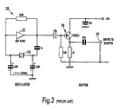
- FIG. 2 illustrates an oscillator circuit 20 for a quartz crystal microbalance, known from Bames C., Sensors and Actuators A., 29 (1991) 59-69.
- Quartz crystal 24 is series connected in a feedback path connecting the output of CMOS inverter 22 to its input, thereby forming an oscillator.
- a one-transistor buffer circuit 26 is coupled to the oscillator and provides an output at 28 to a frequency counter.
- the oscillator will operate in the range 1.7 to 30 MHz but in the prior art was used by Bames at 14 MHz.
- a quartz crystal microbalance using this circuit exhibits the disadvantages outlined above.
- the present invention seeks to alleviate the problems of conventional systems by providing an improved oscillator circuit.
- a quartz crystal microbalance is driven by circuitry which attempts to compensate for Q-losses by means of a gain control facility for controlling the gain of the amplifiers in an oscillator circuit.
- the apparatus includes an oscillator circuit for the crystal, in which a feedback loop has generally similar variable gain amplifiers for providing the regenerative feedback for maintaining oscillation of the crystal.
- the output from the crystal appears as a voltage across a resistor, connected in parallel to the crystal, and serves as an input to the variable gain amplifier following the crystal.
- the output of that amplifier is fed back to phase shifter circuitry in the oscillator feedback loop, and to a second, negative feedback loop which, in turn, controls the gain of the two variable gain amplifiers.
- the apparatus is still only effective over a relatively narrow range of crystal impedances, since the crystal and the resistor, in effect, divide the output of the other variable gain amplifier. Consequently, too high a crystal impedance will prevent a sufficient signal from being fed back to the oscillator circuit to maintain oscillation. On the other hand, too low a crystal impedance would result in the majority of the oscillator's power being applied to the resistor so that insufficient power would be supplied to the crystal.
- analytical apparatus comprising a piezoelectric sensor and an oscillator circuit, coupled to the sensor, to oscillate at a frequency substantially determined by a resonant frequency of the sensor, and to provide an output signal at the oscillator frequency at an output.
- the oscillator circuit incorporates means to maintain a substantially constant drive signal to the piezoelectric sensor.
- the analytical apparatus is a quartz crystal microbalance.
- the substantially constant drive signal is maintained by AGC means within the feedback loop of the oscillator, the gain control signal from which can be used as an indication of the Q of the piezoelectric sensor. It is desirable that the drive signal to the sensor is substantially sinusoidal since this provides greater accuracy, sensitivity and stability for the apparatus. This can be achieved by ensuring that all the elements in the feedback loop providing signal gain and attenuation are configured to operate in a substantially linear mode.
- analytical apparatus comprising a piezoelectric sensor; and an oscillator circuit, coupled to the sensor to oscillate at a frequency substantially determined by a resonant frequency of the sensor, and to provide a first output signal at the oscillator frequency, and in which the oscillator circuit comprises means to provide a second output signal correlated to the 'Q' of the sensor.
- an oscillator circuit comprising a piezoelectric sensor, to oscillate at a frequency substantially determined by a resonant frequency of the sensor and to provide an output signal at the oscillator frequency at an output
- the circuit comprising an amplifier with feedback coupling to the output to an input of the amplifier to form a feedback loop through the amplifier; in which the feedback loop incorporates automatic gain control (AGC) means to maintain a substantially constant drive signal to the piezoelectric sensor.
- AGC automatic gain control
- An oscillator is generally constructed by providing an amplifier with feedback.
- the conditions for oscillation are that the loop gain should be equal to or greater than unity and that the loop gain phase shift is zero (or an integral multiple of 2 ⁇ ).
- the latter condition expresses a requirement that a signal propagating through the amplifier and the feedback network must experience a phase delay of one or more whole cycles at the frequency of oscillation.
- a quartz crystal has a series resonant frequency at which its impedance is zero and a slightly higher parallel resonant frequency at which its impedance is infinite.
- FIG 3 the conceptual block diagram of an improved oscillator is shown.
- gain is provided by amplifier 32 and automatic gain control (AGC) means 33, 34.
- the AGC means comprises a variable gain means (amplifier or attenuator) 33 with gain (amplification/attenuation) controllable by a signal on control input 35. It further comprises means 34 to sense the output signal level from the circuit and to control the. variable gain means in response to the sensed level.
- Feedback in the circuit is provided by line 38 which connects the output of the gain/attenuation element 33 to the input of amplifier 32.
- Quartz crystal 31, which determines the resonant frequency of the oscillator. is connected between the output of amplifier 32 and an earth point, which may be a virtual earth.
- the circuit can be arranged so that the crystal is series connected.
- the output impedance of the driving circuitry must not be too dissimilar to that of the crystal.
- amplifier 32 may be a transconductance amplifier with a high output impedance.
- a conventional oscillator will generally include further capacitive and/or inductive tuning elements in series and/or in parallel with the crystal and/or in the feedback path 38.
- Loop gain is provided by the combination of amplifier 32 and AGC means 33; one or other of these elements may provide some or all of the gain.
- the output of amplifier 32 drives crystal 31 at the resonant frequency and a signal at this frequency appears at output 36.
- the signal level at output 36 is monitored by level sensing means 34 which is coupled to the gain control input 35 of AGC means 33 to control the loop gain. Since the output of AGC means 33 is fed back to the input of amplifier 32, a substantially constant drive at the frequency of oscillation is maintained to crystal 31. A substantially constant signal level is also maintained at output 36.
- maintaining the level of drive signal to quartz crystal which in the general case is any form of piezoelectric sensor, provides a number of advantages.
- the improved drive circuit is capable of maintaining sensor oscillation whilst the sensor is in a range of different or varying environments - for example, air, liquid and flowing liquid.
- the additional damping decreases the Q of the sensor and in the system of Figure 3 the oscillator automatically compensates for this Q reduction.
- the oscillator drive and feedback circuitry (in Figure 3. amplifier 32 and AGC means 33) is therefore preferably linear. In a preferred embodiment described below all the amplifiers in the relevant part of the oscillator. that is those involved in providing a high frequency drive to the crystal. are linear, and preferably have low distortion.
- the features described above assist the oscillator in locking more precisely onto the resonant frequency of the sensor, especially in "difficult" or liquid environments, thus providing a quartz crystal microbalance with improved sensitivity and robustness of use. Furthermore, this oscillator design can more easily follow frequency changes such as occur when, for example, detecting the binding of a ligand to the crystal and a substrate thereon.
- the level of the AGC control signal can be correlated with the 'Q' of the sensor and hence this control signal is also provided at a separate output 37.
- a DC level proportional to the sensor Q value is provided at this output.
- the sensor Q value can empirically be related to the viscosity of a fluid in which the sensor is immersed and the Q output can therefore be used to provide a direct indication of this viscosity. Accordingly in a preferred embodiment of the invention, changes in frequency and Q value are monitored to obtain useful information concerning material subjected to analysis using the sensor.
- the oscillator of Figure 4a includes a piezoelectric sensor 42 driven by an amplifier 46, although in a preferred system this amplifier has unity gain and serves as a buffer.
- amplifier/buffer 46 has two outputs, one driving the sensor 42, the second forming one input to a two-quadrant multiplier 48 which is voltage controlled by input 50 and operates as a voltage controlled attenuator,
- amplifier 46 provides a current drive to a quartz crystal 42 and this current is mirrored to provide an input to the two-quadrant multiplier.
- a second terminal of the sensor 42 is also driven by amplifier 44, which. similarly to amplifier 46. provides an output to a second input of the two-quadrant multiplier 48.
- amplifier 44 is preferably a unity gain buffer.
- the output of multiplier 48 is further amplified by amplifier 52, preferably an operational amplifier. and, as in the conceptual arrangement of Figure 3, a positive feedback path 64 is provided to the input of amplifier/buffer 46.
- the output of amplifier 52 is made available at an output terminal 62; this provides a signal at the frequency of oscillation for input to a frequency counter.
- the output of amplifier 52 is also coupled to rectifier means 54 which detects the signal level and integrator/comparator means 56 which, inter alia, smooths variations of signal level and integrates over a number of cycles.
- the signal level at the output 62 is compared with a signal level amplitude set on adjustment means 58, which is preferably a potentiometer.
- the output of integrator 56 is coupled to the "gain" control input 50 (in a preferred embodiment, an attenuation control input) to maintain an approximately constant level of output signal output 52 and to maintain the drive signal to piezoelectric sensor 42.
- This control signal is, in a preferred embodiment, a DC level, made available at output 60 and proportional to the Q of the sensor.
- dashed line 66 The elements shown enclosed by dashed line 66 are available in a single integrated circuit package, which improves the matching between circuit elements and provides additional advantages of reduced circuit size and power consumption.
- An integrated circuit such as the Comlinear CLC 520 or CLC 522 available from National Semiconductor Corporation, can be used.
- cell gain control input When the oscillator output is rectified and compared with the amplitude reference voltage and the result applied to what can be termed "cell gain control input", a substantially pure sinusoidal oscillation around the crystal resonance is generated with a tight control over loop gain.
- the sensor Q falls the output reduces thus increasing the input to the gain cell and increasing the loop gain to compensate, so keeping the resonance constant.
- the two-quadrant multiplier 48 functions as a "gain cell".
- the feedback path 64 applies positive feedback and the circuit therefore resonates at a resonant frequency of the piezoelectric sensor.
- Figure 4b illustrates the connections to input amplifier 46.
- This amplifier is unusual in that it has a single input 46A but two outputs, 46B and 46C.
- the functioning of this amplifier was outlined above but it is helpful to consider another equivalent way of looking at its function.
- the output 46B reflects the reactance of a load imposed on the second (intermediate) output 46C, so that the impedance placed on output 46C controls the gain between input 46A and output 46B. In the preferred embodiment there is unity gain between 46A and 46C but variable gain between 46A and 46B.
- Amplifier/buffer 44 is similar.
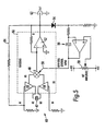
- Figure 5 shows a detailed circuit diagram of a basic oscillator circuit constructed in accordance with the block diagram of Figure 4a.
- FIGs 4 to 7 like elements are indicated by the same reference numerals.
- the main elements of Figure 4a can be identified in Figure 5, that is crystal 42, amplifiers 44 and 46, multiplier 48 with attenuation/gain control input 50, amplifier 52, positive feedback path 64, rectifying means 54, integrator/comparator 56 and output level adjust means 58.
- the two input buffers 44 and 46 convert the input voltage to a current that is a function of the differential input voltage and the value of the gain-setting impedance of crystal 42. This current is then mirrored to a gain stage (not shown) and attenuated by voltage controlled two-quadrant multiplier 48, after which it is converted to a voltage by output amplifier 52 with gain set by feedback resistor R4.
- the input, output and gain control signals are all voltages.
- An output at the oscillator frequency is provided at 62 and the components within the dashed line 66 can be obtained within a single integrated circuit.
- amplifier 46 has an inverting input whilst amplifier 44 has a non-inverting input, and that amplifier 52 is an operational amplifier.
- Rectifier means 54 can at its simplest, be a single diode and the integrator/comparator 56 can again be constructed from a single operational amplifier. The skilled person will be aware that many variations on these basic circuit elements are possible. For example, other rectifying elements or more sophisticated full wave rectifiers could be used for the rectifier means. Many conventional variations are possible on integrator means 56.
- Figure 6 shows a detailed circuit of an embodiment incorporating various additions desirable in a practical implementation. It can be seen that this circuit closely corresponds to that of Figure 5. with the addition of amplifiers/buffers 70 and 72 for the Q output 60 and the frequency output 62 respectively. Additional (low pass) filtering 68 has also been incorporated in a second feedback path from the output of amplifier 52 back to its inverting ("-") input. Positive and negative 5 volt power supplies 74 are also shown. In Figure 6 connections to the sensor 42 are made via terminal 76 and connecting wires 78. Wires 78 may be. for example, a screened cable or a balanced twisted-pair type connection. Connectors 76, which may be a single connector, are chosen in accordance with conventional practice, to be suitable for relatively low-level high frequency (I - 100 MHz) signals.
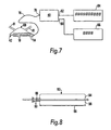
- Figure 7 shows one example of a complete quartz crystal microbalance including oscillator 40 coupled-via-connection 76 and wires 78 to crystal sensor 42 in a flow cell 80, with fluid inlet and outlet connections 81.
- the flow cell is preferably arranged so that fluid flowing through the cell contacts only a single face of the sensor, to improve the system performance when used with ionic, and hence conducting fluids, although the sensor may also be configured to operate in a fluid bath.
- the frequency output 62 is coupled to a digital frequency counter 84 with a resolution of the order of 1 Hz; the Q output 60 is coupled to digital voltmeter 86.
- Figure 8 shows an alternative arrangement of a sensor with quartz crystal 88 with lead wires 90 sandwiched between O rings 94 and 96 and resting on a cover slip 98. This arrangement provides a well 92 which can be partially filled with liquid; a simpler configuration can dispense with cover slip 98 and lower O ring 96. Generally speaking, gold sensor electrodes are preferred because of their reduced tendency to oxidise.
- a quartz crystal microbalance such as that shown in Figure 7, can be used for a variety of purposes.
- the apparatus is sensitive, among other things, to the density and viscosity of a liquid in which the sensor is immersed and can detect small mass changes even where a large tare is necessary to take account of initially deposited material.
- One actually constructed circuit was found to be stable to 1 ⁇ 4 Hz/day, obviating a need for a reference crystal.
- the apparatus can also detect the binding of ligands of much smaller molecular weight than is possible with conventional quartz crystal microbalances, allowing direct screening of potential drug candidates.
- the circuits described herein allow the detection of binding of ligands of molecular weight less than 600, for example ligands of molecular weight circa 180 or less, such as glucose.
- the apparatus can be used to provide improved immunoassay apparatus.
- a typical immunoassay involves detecting the binding of an antigen to an antibody, or of a receptor to a ligand.
- One immunoassay process known as the Bayston test (Bayston R., J. Clin. Path., 25 (1972) 718-720). relies on the antibody-antigen binding process in solution to form aggregates or clumps producing a visible precipitate. This process can be monitored using a quartz crystal microbalance, which is thought to respond to changes in the viscosity and density of the medium supporting the antibody and antigen. These changes cause a drop in the resonant frequency of the sensor, the largest drop occurring at the point of full agglutination and hence a quartz crystal microbalance simplifies detection of the titre of agglutination.
- the improved quartz crystal microbalance can be used to monitor the characteristics of bacteria in solution.
- one face of the piezoelectric sensor is coated with fibronectin to which bacteria such as Staphylococcus Epidermidis will bind.
- the microbalance also has the required sensitivity and robustness for a real time monitoring system to allow continuous assay of a sample, for example, to determine the number of cells in a solution.
- the shift in resonant frequency of the sensor has been found to be related to the bacterial concentration, with a roughly linear relationship between the frequency shift and a logarithm of the bacterial concentration.
- local changes in solution viscosity and density in the region of the electrode surface are believed to influence the resonant frequency of the sensor. It is believed that this effect is present even when there is no actual binding of a species directly to the crystal surface, but merely a local modification to the liquid around the vibrating sensor.
- the apparatus can also be used to investigate binding and similar processes as they occur in complete or substantially complete cells.
- the cells can be grown onto the sensor following which the small additional mass changes due to binding and transport mechanisms at a cell surface can be monitored if desired, in vivo. This is possible because of the ability of the oscillator circuit to follow large changes in the resonant frequency of the crystal whilst maintaining oscillation and maintaining the sensitivity of the system to very small mass changes.
- relatively thick multi-layer structures for example 20 layers of protein - can be built up on the sensor before binding events are monitored.
Landscapes
- Physics & Mathematics (AREA)
- General Physics & Mathematics (AREA)
- General Health & Medical Sciences (AREA)
- Immunology (AREA)
- Life Sciences & Earth Sciences (AREA)
- Chemical & Material Sciences (AREA)
- Analytical Chemistry (AREA)
- Biochemistry (AREA)
- Acoustics & Sound (AREA)
- Health & Medical Sciences (AREA)
- Pathology (AREA)
- Oscillators With Electromechanical Resonators (AREA)
- Investigating Or Analysing Biological Materials (AREA)
- Apparatus Associated With Microorganisms And Enzymes (AREA)
- Crystals, And After-Treatments Of Crystals (AREA)
- Silicon Compounds (AREA)
- Seal Device For Vehicle (AREA)
- Glass Compositions (AREA)
Abstract
Description
- This invention generally relates to a novel device, being an analytical apparatus comprising an oscillating piezoelectric sensor and more particularly to an improved quartz crystal microbalance and the use thereof.
- A quartz crystal microbalance is a device for detecting and measuring very small changes in mass. Its primary components are a quartz crystal and an oscillator circuit coupled to the quartz crystal to produce an output at a resonant frequency of the crystal. The output frequency, which is typically around 10 MHz, is measured to a high degree of accuracy, for example, with a frequency counter. The quartz crystal is, unlike the crystals normally used in electronic circuits, unencapsulated, so that it can interact with its environment. The deposition of small quantities of material onto the crystal changes its resonant frequency and allows the determination of the mass of material deposited. Typically frequency changes are of the order of a few Hz to a few tens of Hz and changes of the order of nanograms in the mass of material deposited can be detected.
- The piezoelectric sensor in research analytical apparatus is typically a thin slice of quartz from an artificially grown crystal, although other piezoelectric materials such as tourmaline, ethylene diamine tartrate, ADP, KDP and Rochelle salt can also be used. Quartz has the advantages of being chemically unreactive and insoluble in water, as well as being relatively temperature insensitive. A typical quartz sensor 10 for a microbalance is shown in Figure 1. The quartz crystal 16 is typically a circular "AT-cut" with metal electrodes 18 on opposing faces. The electrodes are typically sputtered thin (200nm) films of gold, silver or titanium, possibly with a sub-layer for improved adhesion. Lead wires 14 attach to the electrodes and also provides mechanical support for the crystal, as well as some degree of isolation from base 12 of the sensor and lead out wires 15. The crystal is typically around 1cm in diameter. The change in resonant frequency. ΔF of an AT-cut quartz crystal of area, A. vibrating in air at fundamental frequency. F. when the mass of the crystal is changed by ΔM, is given approximately by:
- The quartz crystal microbalance is most frequently used to measure mass but can also be used to detect changes in the viscosity and/or density of a liquid, since when vibrating in a liquid all these factors effect the vibrational frequency. Thus the shift in frequency of a quartz crystal on immersion in a liquid, ΔF, is given by:
- ΔF =
- Change in Frequency
- F0 =
- Resonance Frequency
- ηLρL =
- Liquid absolute density and viscosity
- µQ ρQ =
- Quartz elastic modulus and density.
- A quartz crystal microbalance can be used as a bio-sensor, that is as a device which uses as part of the sensor, or is sensitive to, material of biological origin. Typically part of one or both electrodes of the sensor are coated with material which is capable of binding with a target bio-molecule or cell. When such a receptor is exposed to the target ("ligand") compound, the ligand is bound to the substrate causing a change in mass ΔM of the sensor, and/or viscosity/density changes in the local microenvironment and a consequent change in its vibrational frequency.
- There is a general need for improvements in the sensitivity and effectiveness of known quartz crystal microbalances. More particularly, the oscillator drive circuits of conventional microbalances lack stability and precision, particularly when the sensor is immersed in a liquid. When a crystal surface is immersed in a liquid the "Q" of the crystal (a measure of the sharpness of the resonance or, equivalently, the energy dissipated per cycle) will drop substantially and the resonant frequency will shift slightly. The Q drop is due to the damping effect caused by the absorption of energy by the liquid; the change in resonant frequency is due to the dynamic mass of the liquid on the crystal face. When a crystal resonates its impedance drops from almost infinity to about 50 - 200 Ω; when immersed the impedance at resonance can be 100 KΩ or higher. In order that the apparatus can operate with the sensor both in and out of a liquid it is necessary to provide a system with a wide dynamic range to accurately determine the sensor's resonant frequency over this wide range of impedances. Although quartz crystal microbalances have been able to operate in either liquid or air, a difficulty arises when the system is required to operate with the sensor in either medium. Furthermore. when operated in a liquid prior devices often exhibit a lack of stability, sensitivity and precision, possibly related to the broader resonance and greater energy dissipation of the immersed sensor. Efforts to counteract some of this variability have included using dual matched oscillators, comparing the frequencies of working and reference crystals (Dunham G.C., Benson N.H., Petalenz D. and Janata J., Anal. Chem.,67 (1995) 267- 272).
- There is also a need for improved screening processes for rapid evaluation of compounds of potentially therapeutic benefit. Pharmaceutical companies typically synthesise thousands of compounds, which are then screened in order to identify those which interact with a target molecule. Typically one or other of the target and ligand are labelled with a radioactive or fluorescent tag, but such techniques are slow, expensive and require the handling of dangerous materials, and the labelling may interfere with the receptor-ligand interaction. A further problem is therefore the need for improved screening processes and quartz crystal microbalances promise some advantages in this field. However, in this context it is desirable to have a sensor-oscillator system which is stable even in a flowing liquid and which, in this configuration, is sensitive enough to allow bio-molecular interactions on the surface of the crystal electrode to be monitored in real time.
- Figure 2 illustrates an oscillator circuit 20 for a quartz crystal microbalance, known from Bames C., Sensors and Actuators A., 29 (1991) 59-69. Quartz crystal 24 is series connected in a feedback path connecting the output of CMOS inverter 22 to its input, thereby forming an oscillator. A one-transistor buffer circuit 26 is coupled to the oscillator and provides an output at 28 to a frequency counter. The oscillator will operate in the range 1.7 to 30 MHz but in the prior art was used by Bames at 14 MHz. A quartz crystal microbalance using this circuit exhibits the disadvantages outlined above. The present invention seeks to alleviate the problems of conventional systems by providing an improved oscillator circuit.
- In the apparatus described in US 4,788,466, a quartz crystal microbalance, is driven by circuitry which attempts to compensate for Q-losses by means of a gain control facility for controlling the gain of the amplifiers in an oscillator circuit. The apparatus includes an oscillator circuit for the crystal, in which a feedback loop has generally similar variable gain amplifiers for providing the regenerative feedback for maintaining oscillation of the crystal. The output from the crystal appears as a voltage across a resistor, connected in parallel to the crystal, and serves as an input to the variable gain amplifier following the crystal. The output of that amplifier is fed back to phase shifter circuitry in the oscillator feedback loop, and to a second, negative feedback loop which, in turn, controls the gain of the two variable gain amplifiers. However, despite the gain control, the apparatus is still only effective over a relatively narrow range of crystal impedances, since the crystal and the resistor, in effect, divide the output of the other variable gain amplifier. Consequently, too high a crystal impedance will prevent a sufficient signal from being fed back to the oscillator circuit to maintain oscillation. On the other hand, too low a crystal impedance would result in the majority of the oscillator's power being applied to the resistor so that insufficient power would be supplied to the crystal.
- According to the invention, there is provided a method and apparatus as defined in the independent method and apparatus claims, claims 1 and 9, respectively.
- We will describe analytical apparatus comprising a piezoelectric sensor and an oscillator circuit, coupled to the sensor, to oscillate at a frequency substantially determined by a resonant frequency of the sensor, and to provide an output signal at the oscillator frequency at an output. The oscillator circuit incorporates means to maintain a substantially constant drive signal to the piezoelectric sensor. In a preferred embodiment the analytical apparatus is a quartz crystal microbalance. The substantially constant drive signal is maintained by AGC means within the feedback loop of the oscillator, the gain control signal from which can be used as an indication of the Q of the piezoelectric sensor. It is desirable that the drive signal to the sensor is substantially sinusoidal since this provides greater accuracy, sensitivity and stability for the apparatus. This can be achieved by ensuring that all the elements in the feedback loop providing signal gain and attenuation are configured to operate in a substantially linear mode.
- We will further describe a method of measuring a characteristic of an oscillating piezoelectric sensor in a fluid medium, comprising providing an oscillating drive signal to the sensor and characterised in that the method further comprises controlling the drive signal such that it is maintained at an approximately constant level despite changes in the fluid medium.
- We will also describe analytical apparatus comprising a piezoelectric sensor; and an oscillator circuit, coupled to the sensor to oscillate at a frequency substantially determined by a resonant frequency of the sensor, and to provide a first output signal at the oscillator frequency, and in which the oscillator circuit comprises means to provide a second output signal correlated to the 'Q' of the sensor.
- We will further describe an oscillator circuit comprising a piezoelectric sensor, to oscillate at a frequency substantially determined by a resonant frequency of the sensor and to provide an output signal at the oscillator frequency at an output, the circuit comprising an amplifier with feedback coupling to the output to an input of the amplifier to form a feedback loop through the amplifier; in which the feedback loop incorporates automatic gain control (AGC) means to maintain a substantially constant drive signal to the piezoelectric sensor.
- In order to promote a fuller understanding of these and other aspects of the invention, some embodiments will now be described, by way of example only, with reference to the accompanying drawings in which:
- Figure 1 shows a typical quartz crystal sensor for a microbalance;
- Figure 2 shows a known quartz crystal oscillator circuit;
- Figure 3 shows a conceptual block diagram of an improved oscillator circuit;
- Figure 3a shows a block diagram of a preferred embodiment of an oscillator in accordance with the present invention;
- Figure 4b shows an input amplifier for an oscillator,
- Figure 5 shows a detailed circuit diagram of a first embodiment of an oscillator in accordance with the present invention;
- Figure 6 shows a detailed circuit diagram of a second embodiment in accordance with the present invention;
- Figure 7 shows a quartz crystal microbalance incorporating an improved oscillator circuit;
- Figure 8 shows a quartz crystal sensor cell.
-
- An oscillator is generally constructed by providing an amplifier with feedback. The conditions for oscillation are that the loop gain should be equal to or greater than unity and that the loop gain phase shift is zero (or an integral multiple of 2π). The latter condition expresses a requirement that a signal propagating through the amplifier and the feedback network must experience a phase delay of one or more whole cycles at the frequency of oscillation. A quartz crystal has a series resonant frequency at which its impedance is zero and a slightly higher parallel resonant frequency at which its impedance is infinite.
- In Figure 3 the conceptual block diagram of an improved oscillator is shown. In this circuit gain is provided by amplifier 32 and automatic gain control (AGC) means 33, 34. The AGC means comprises a variable gain means (amplifier or attenuator) 33 with gain (amplification/attenuation) controllable by a signal on control input 35. It further comprises means 34 to sense the output signal level from the circuit and to control the. variable gain means in response to the sensed level. Feedback in the circuit is provided by line 38 which connects the output of the gain/attenuation element 33 to the input of amplifier 32. Quartz crystal 31, which determines the resonant frequency of the oscillator. is connected between the output of amplifier 32 and an earth point, which may be a virtual earth. Alternatively the circuit can be arranged so that the crystal is series connected. In the parallel-connected configuration shown, in order for crystal 31 to properly determine the resonant frequency of the circuit, the output impedance of the driving circuitry must not be too dissimilar to that of the crystal. Thus if the amplifier has a low output impedance the crystal can be driven via a resistor: alternatively amplifier 32 may be a transconductance amplifier with a high output impedance. A conventional oscillator will generally include further capacitive and/or inductive tuning elements in series and/or in parallel with the crystal and/or in the feedback path 38. However in the circuits described herein it is preferable to reduce such additional elements to a minimum so that the frequency of oscillation is as much as possible determined by the resonant frequency of the crystal alone. It will be seen later that in a preferred embodiment the passive elements of the oscillator drive circuit are, disregarding stray capacitance, almost entirely resistive.
- Loop gain is provided by the combination of amplifier 32 and AGC means 33; one or other of these elements may provide some or all of the gain. In operation, the output of amplifier 32 drives crystal 31 at the resonant frequency and a signal at this frequency appears at output 36. The signal level at output 36 is monitored by level sensing means 34 which is coupled to the gain control input 35 of AGC means 33 to control the loop gain. Since the output of AGC means 33 is fed back to the input of amplifier 32, a substantially constant drive at the frequency of oscillation is maintained to crystal 31. A substantially constant signal level is also maintained at output 36. When used with a quartz crystal microbalance or similar apparatus, maintaining the level of drive signal to quartz crystal, which in the general case is any form of piezoelectric sensor, provides a number of advantages. The improved drive circuit is capable of maintaining sensor oscillation whilst the sensor is in a range of different or varying environments - for example, air, liquid and flowing liquid. In a liquid, as described above the additional damping decreases the Q of the sensor and in the system of Figure 3 the oscillator automatically compensates for this Q reduction.
- It has also been found that it is important to provide a substantially sinusoidal drive signal to the crystal. When the crystal is damped, for example by a liquid. if a significantly non-sinusoidal or square wave is driving it, there is a tendency for the crystal to hop to an overtone frequency. This tendency is reduced with a sinusoidal drive. The oscillator drive and feedback circuitry (in Figure 3. amplifier 32 and AGC means 33) is therefore preferably linear. In a preferred embodiment described below all the amplifiers in the relevant part of the oscillator. that is those involved in providing a high frequency drive to the crystal. are linear, and preferably have low distortion.
- The features described above assist the oscillator in locking more precisely onto the resonant frequency of the sensor, especially in "difficult" or liquid environments, thus providing a quartz crystal microbalance with improved sensitivity and robustness of use. Furthermore, this oscillator design can more easily follow frequency changes such as occur when, for example, detecting the binding of a ligand to the crystal and a substrate thereon.
- It has been found that the level of the AGC control signal can be correlated with the 'Q' of the sensor and hence this control signal is also provided at a separate output 37. In the detailed circuit described with reference to Figure 6, a DC level proportional to the sensor Q value is provided at this output. It has also been found that the sensor Q value can empirically be related to the viscosity of a fluid in which the sensor is immersed and the Q output can therefore be used to provide a direct indication of this viscosity. Accordingly in a preferred embodiment of the invention, changes in frequency and Q value are monitored to obtain useful information concerning material subjected to analysis using the sensor.
- In Figure 3 the crystal 31 has been shown connected in parallel with the amplifier output, but the skilled person will understand that the crystal could also be connected at other positions in the circuit and could, for example, be series connected.
- Referring now to Figure 4a, a block diagram of a preferred embodiment of an oscillator 40 is shown, based on the conceptual arrangement of Figure 3. Like the conceptual system, the oscillator of Figure 4a includes a piezoelectric sensor 42 driven by an amplifier 46, although in a preferred system this amplifier has unity gain and serves as a buffer. In the embodiment shown, amplifier/buffer 46 has two outputs, one driving the sensor 42, the second forming one input to a two-quadrant multiplier 48 which is voltage controlled by input 50 and operates as a voltage controlled attenuator, In a specific embodiment, amplifier 46 provides a current drive to a quartz crystal 42 and this current is mirrored to provide an input to the two-quadrant multiplier. In the arrangement of Figure 4a, a second terminal of the sensor 42 is also driven by amplifier 44, which. similarly to amplifier 46. provides an output to a second input of the two-quadrant multiplier 48. Again. amplifier 44 is preferably a unity gain buffer. The output of multiplier 48 is further amplified by amplifier 52, preferably an operational amplifier. and, as in the conceptual arrangement of Figure 3, a positive feedback path 64 is provided to the input of amplifier/buffer 46. The output of amplifier 52 is made available at an output terminal 62; this provides a signal at the frequency of oscillation for input to a frequency counter.
- The output of amplifier 52 is also coupled to rectifier means 54 which detects the signal level and integrator/comparator means 56 which, inter alia, smooths variations of signal level and integrates over a number of cycles. The signal level at the output 62 is compared with a signal level amplitude set on adjustment means 58, which is preferably a potentiometer. The output of integrator 56 is coupled to the "gain" control input 50 (in a preferred embodiment, an attenuation control input) to maintain an approximately constant level of output signal output 52 and to maintain the drive signal to piezoelectric sensor 42. This control signal is, in a preferred embodiment, a DC level, made available at output 60 and proportional to the Q of the sensor.
- The elements shown enclosed by dashed line 66 are available in a single integrated circuit package, which improves the matching between circuit elements and provides additional advantages of reduced circuit size and power consumption. An integrated circuit such as the Comlinear CLC 520 or CLC 522 available from National Semiconductor Corporation, can be used. When the oscillator output is rectified and compared with the amplitude reference voltage and the result applied to what can be termed "cell gain control input", a substantially pure sinusoidal oscillation around the crystal resonance is generated with a tight control over loop gain. When the sensor Q falls the output reduces thus increasing the input to the gain cell and increasing the loop gain to compensate, so keeping the resonance constant. In the circuit of Figure 4a the two-quadrant multiplier 48 functions as a "gain cell". The feedback path 64 applies positive feedback and the circuit therefore resonates at a resonant frequency of the piezoelectric sensor.
- Figure 4b illustrates the connections to input amplifier 46. This amplifier is unusual in that it has a single input 46A but two outputs, 46B and 46C. The functioning of this amplifier was outlined above but it is helpful to consider another equivalent way of looking at its function. The output 46B reflects the reactance of a load imposed on the second (intermediate) output 46C, so that the impedance placed on output 46C controls the gain between input 46A and output 46B. In the preferred embodiment there is unity gain between 46A and 46C but variable gain between 46A and 46B. Amplifier/buffer 44 is similar.
- Figure 5 shows a detailed circuit diagram of a basic oscillator circuit constructed in accordance with the block diagram of Figure 4a. In Figures 4 to 7, like elements are indicated by the same reference numerals. Thus, the main elements of Figure 4a can be identified in Figure 5, that is crystal 42, amplifiers 44 and 46, multiplier 48 with attenuation/gain control input 50, amplifier 52, positive feedback path 64, rectifying means 54, integrator/comparator 56 and output level adjust means 58.
- The two input buffers 44 and 46 convert the input voltage to a current that is a function of the differential input voltage and the value of the gain-setting impedance of crystal 42. This current is then mirrored to a gain stage (not shown) and attenuated by voltage controlled two-quadrant multiplier 48, after which it is converted to a voltage by output amplifier 52 with gain set by feedback resistor R4. Thus the input, output and gain control signals are all voltages.
- An output at the oscillator frequency is provided at 62 and the components within the dashed line 66 can be obtained within a single integrated circuit. In the detailed circuit shown it can be seen that amplifier 46 has an inverting input whilst amplifier 44 has a non-inverting input, and that amplifier 52 is an operational amplifier. Rectifier means 54 can at its simplest, be a single diode and the integrator/comparator 56 can again be constructed from a single operational amplifier. The skilled person will be aware that many variations on these basic circuit elements are possible. For example, other rectifying elements or more sophisticated full wave rectifiers could be used for the rectifier means. Many conventional variations are possible on integrator means 56.
- Figure 6 shows a detailed circuit of an embodiment incorporating various additions desirable in a practical implementation. It can be seen that this circuit closely corresponds to that of Figure 5. with the addition of amplifiers/buffers 70 and 72 for the Q output 60 and the frequency output 62 respectively. Additional (low pass) filtering 68 has also been incorporated in a second feedback path from the output of amplifier 52 back to its inverting ("-") input. Positive and negative 5 volt power supplies 74 are also shown. In Figure 6 connections to the sensor 42 are made via terminal 76 and connecting wires 78. Wires 78 may be. for example, a screened cable or a balanced twisted-pair type connection. Connectors 76, which may be a single connector, are chosen in accordance with conventional practice, to be suitable for relatively low-level high frequency (I - 100 MHz) signals.
- Figure 7 shows one example of a complete quartz crystal microbalance including oscillator 40 coupled-via-connection 76 and wires 78 to crystal sensor 42 in a flow cell 80, with fluid inlet and outlet connections 81. The flow cell is preferably arranged so that fluid flowing through the cell contacts only a single face of the sensor, to improve the system performance when used with ionic, and hence conducting fluids, although the sensor may also be configured to operate in a fluid bath.
- The frequency output 62 is coupled to a digital frequency counter 84 with a resolution of the order of 1 Hz; the Q output 60 is coupled to digital voltmeter 86. Figure 8 shows an alternative arrangement of a sensor with quartz crystal 88 with lead wires 90 sandwiched between O rings 94 and 96 and resting on a cover slip 98. This arrangement provides a well 92 which can be partially filled with liquid; a simpler configuration can dispense with cover slip 98 and lower O ring 96. Generally speaking, gold sensor electrodes are preferred because of their reduced tendency to oxidise.
- A quartz crystal microbalance such as that shown in Figure 7, can be used for a variety of purposes. The apparatus is sensitive, among other things, to the density and viscosity of a liquid in which the sensor is immersed and can detect small mass changes even where a large tare is necessary to take account of initially deposited material. One actually constructed circuit was found to be stable to ¼ Hz/day, obviating a need for a reference crystal. The apparatus can also detect the binding of ligands of much smaller molecular weight than is possible with conventional quartz crystal microbalances, allowing direct screening of potential drug candidates. For example, the circuits described herein allow the detection of binding of ligands of molecular weight less than 600, for example ligands of molecular weight circa 180 or less, such as glucose.
- The apparatus can be used to provide improved immunoassay apparatus. A typical immunoassay involves detecting the binding of an antigen to an antibody, or of a receptor to a ligand. One immunoassay process, known as the Bayston test (Bayston R., J. Clin. Path., 25 (1972) 718-720). relies on the antibody-antigen binding process in solution to form aggregates or clumps producing a visible precipitate. This process can be monitored using a quartz crystal microbalance, which is thought to respond to changes in the viscosity and density of the medium supporting the antibody and antigen. These changes cause a drop in the resonant frequency of the sensor, the largest drop occurring at the point of full agglutination and hence a quartz crystal microbalance simplifies detection of the titre of agglutination.
- The improved quartz crystal microbalance can be used to monitor the characteristics of bacteria in solution. For example, one face of the piezoelectric sensor is coated with fibronectin to which bacteria such as Staphylococcus Epidermidis will bind. The microbalance also has the required sensitivity and robustness for a real time monitoring system to allow continuous assay of a sample, for example, to determine the number of cells in a solution. In such a configuration the shift in resonant frequency of the sensor has been found to be related to the bacterial concentration, with a roughly linear relationship between the frequency shift and a logarithm of the bacterial concentration. In both this and the previous example, local changes in solution viscosity and density in the region of the electrode surface are believed to influence the resonant frequency of the sensor. It is believed that this effect is present even when there is no actual binding of a species directly to the crystal surface, but merely a local modification to the liquid around the vibrating sensor.
- The apparatus can also be used to investigate binding and similar processes as they occur in complete or substantially complete cells. The cells can be grown onto the sensor following which the small additional mass changes due to binding and transport mechanisms at a cell surface can be monitored if desired, in vivo. This is possible because of the ability of the oscillator circuit to follow large changes in the resonant frequency of the crystal whilst maintaining oscillation and maintaining the sensitivity of the system to very small mass changes. Similarly, relatively thick multi-layer structures - for example 20 layers of protein - can be built up on the sensor before binding events are monitored.
Claims (21)
- Analytical apparatus comprising a piezoelectric sensor (42); and an oscillator circuit (40) coupled to the piezoelectric sensor (42) and adapted to provide an output signal at an output (62), wherein the output signal oscillates at the same frequency as the oscillator circuit (40), said frequency being substantially determined by the piezoelectric sensor (42), the oscillator circuit incorporates means to maintain a substantially constant oscillating current drive signal to the piezoelectric sensor (42), said means including an amplifier (52) with a first feedback loop controlling an input of the amplifier (52) to form an ACG feedback loop through the amplifier and with a second feedback loop to said piezoelectric sensor whereby the current through the piezoelectric sensor (42) is mirrored to provide a signal to the amplifier input controlled by the AGC feedback loop.
- Apparatus as claimed in claim 1 wherein the passive elements of the oscillator circuit are entirely resistive.
- Apparatus as claimed in any of the preceding claims wherein the AGC feedback loop comprises rectification means (54), integrator means (56) and variable gain means (48) responsive to the integrator means (56).
- Apparatus as claimed in any of the preceding claims further comprising means to provide a second output signal (60) derived from a gain control signal output by the AGC feedback loop and correlated to the 'Q' of the piezoelectric sensor (42).
- Apparatus as claimed in any one of claims 1 to 4 wherein the drive signal to the piezoelectric sensor (42) is provided by a unity gain buffer (46).
- Apparatus as claimed in any one of claims 1 to 5 wherein the piezoelectric sensor (42) has two terminals (14), both of which are actively driven.
- Apparatus as claimed in claim 6 when appended to claim 5, wherein the oscillator circuit (40) includes an integrated circuit having two unity gain buffers (44, 46) each having a respective first output (C) connected to a respective terminal of the piezoelectric sensor (42) to drive the latter, each unity gain buffer also having a respective second output (B), providing a current mirrored from the current through the piezoelectric sensor, connected to a respective input of a two quadrant multiplier (48) which is voltage controlled by an input (50), connected in the AGC feedback loop, the multiplier (48) functioning as a voltage controlled attenuator, the integrated circuit also including said amplifier (52), which is an operational amplifier the inverting input of which is connected to the output of the multiplier (48), the output of the amplifier (52) being made available to the output (62).
- Apparatus as claimed in any of claims 1 to 7 for measuring a characteristic of a material of interest wherein the piezoelectric sensor (42) has a structure or compound that interacts with said material of interest attached either to a surface of the sensor or to an electrode (18) on the piezoelectric sensor (42).
- A method of driving a piezoelectric sensor, comprising the steps of supplying a substantially constant oscillating current drive signal to the piezoelectric sensor at a frequency substantially determined by the resonant frequency of the piezoelectric sensor and maintaining the level of the drive signal by means of an amplifier (52) with a first feedback loop controlling an input of the amplifier (52) to form an AGC feedback loop through the amplifier, and with a second feedback loop to said piezoelectric sensor whereby the current through the piezoelectric sensor (42) is mirrored to provide a signal to the amplifier input controlled by the AGC feedback loop.
- A method as claimed in claim 9 wherein the piezoelectric sensor (42) has two terminals and said providing an oscillating drive signal further comprises actively driving both terminals of the piezoelectric sensor (42).
- A method as claimed in either claim 9 or claim 10 wherein the drive signal is provided by a an integrated circuit having two unity gain buffers (44, 46) each having a respective first output (C) connected to a respective terminal of the piezoelectric sensor (42) to drive the latter, each unity gain buffer having a respective second output (B), providing a current mirrored from the current through the piezoelectric sensor, connected to a respective input of a two quadrant multiplier (48) which is voltage controlled by an input (50), connected in the AGC feedback loop, the multiplier (48) functioning as a voltage controlled attenuator, the integrated circuit also including said amplifier (52), which is an operational amplifier the inverting input of which is connected to the output of the multiplier (48), the output of the amplifier (52) being made available to the output (62).
- Analytical apparatus according to any of claims 1 to 8, in which the oscillator circuit includes a driver amplifier (46) having an input (46A), which receives a voltage signal from the output of the amplifier (52), a first output (46B), connected to the input of said amplifier (52), and a second output (46C), connected to the piezoelectric sensor (42), wherein the signal at the first output (46B) reflects the reactance of the load imposed on the second output (46C) so that the impedance placed on the second output (46C) controls the gain between the input (46A)and first output (46B) of the driver amplifier (46).
- Use of the apparatus of any one of claims 1 to 8 to detect cells or biochemically active compounds.
- Use of the apparatus of any one of claims 1 to 8 to detect an interaction between a cell and a target material.
- Use of the apparatus of any one of claims 1 to 8 to perform an immunoassay.
- Use of the apparatus of any one of claims 1 to 8 to detect a titre of antibody-antigen agglutination.
- Use of the apparatus of any one of claims 1 to 8 to monitor, in solution, a bacterial characteristic.
- Use of the apparatus of any one of claims 1 to 9 to measure the concentration of bacteria in a solution.
- Use of the apparatus of any of claims 1 to 8 to determine the viscosity and density of a liquid.
- Use of the apparatus of any of claims 1 to 8 to determine the binding of ligands of molecular weight less than 600.
- Use of the apparatus of any of the claims 1 to 8 to determine the binding of a ligand.
Applications Claiming Priority (3)
| Application Number | Priority Date | Filing Date | Title |
|---|---|---|---|
| GBGB9823410.7A GB9823410D0 (en) | 1998-10-26 | 1998-10-26 | Novel device |
| GB9823410 | 1998-10-26 | ||
| PCT/EP1999/008148 WO2000025118A1 (en) | 1998-10-26 | 1999-10-21 | Quartz crystal microbalance with feedback loop for automatic gain control |
Publications (2)
| Publication Number | Publication Date |
|---|---|
| EP1125117A1 EP1125117A1 (en) | 2001-08-22 |
| EP1125117B1 true EP1125117B1 (en) | 2005-04-27 |
Family
ID=10841307
Family Applications (1)
| Application Number | Title | Priority Date | Filing Date |
|---|---|---|---|
| EP99952627A Expired - Lifetime EP1125117B1 (en) | 1998-10-26 | 1999-10-21 | Quartz crystal microbalance with feedback loop for automatic gain control |
Country Status (7)
| Country | Link |
|---|---|
| US (2) | US6647764B1 (en) |
| EP (1) | EP1125117B1 (en) |
| JP (1) | JP4700810B2 (en) |
| AT (1) | ATE294385T1 (en) |
| DE (1) | DE69925015T9 (en) |
| GB (1) | GB9823410D0 (en) |
| WO (1) | WO2000025118A1 (en) |
Cited By (2)
| Publication number | Priority date | Publication date | Assignee | Title |
|---|---|---|---|---|
| DE102010005859B3 (en) * | 2010-01-26 | 2011-05-19 | Christian-Albrechts-Universität Zu Kiel | Apparatus and method for detecting biological material |
| US8316711B2 (en) | 2006-08-02 | 2012-11-27 | Endress + Hauser Gmbh + Co. Kg | Apparatus for ascertaining and/or monitoring a process variable of a medium |
Families Citing this family (47)
| Publication number | Priority date | Publication date | Assignee | Title |
|---|---|---|---|---|
| US6832506B1 (en) * | 1999-11-16 | 2004-12-21 | Julian Mason | Apparatus and method for measuring a property of a liquid |
| WO2002012873A2 (en) * | 2000-08-08 | 2002-02-14 | Smithkline Beecham P.L.C. | Quartz crystal microbalance |
| DE10203475A1 (en) | 2002-01-18 | 2003-07-31 | Bosch Gmbh Robert | Device for measuring viscosity and / or density |
| JP3911191B2 (en) * | 2002-04-26 | 2007-05-09 | 株式会社アルバック | Analysis method |
| AT414274B (en) * | 2002-11-07 | 2006-10-15 | Avl List Gmbh | PROCESS FOR DETERMINING PHYSICAL OR CHEMICAL PARAMETERS OF A THIN MATERIAL LAYER |
| JP2004245613A (en) * | 2003-02-12 | 2004-09-02 | Japan Science & Technology Agency | Flow cell type QCM apparatus and sample measuring method |
| SE0300375D0 (en) * | 2003-02-12 | 2003-02-12 | Attana Ab | Piezoelectric resonator |
| US7042134B2 (en) * | 2003-03-31 | 2006-05-09 | Suren Systems, Ltd. | Transconductance circuit for piezoelectric transducer |
| US7352107B2 (en) * | 2003-03-31 | 2008-04-01 | Suren Systems, Ltd. | Transconductance circuit for piezoelectric transducer |
| US7622845B2 (en) | 2003-03-31 | 2009-11-24 | Suren Systems, Ltd. | Piezoelectric transducer signal processing circuit |
| US7141910B2 (en) * | 2003-03-31 | 2006-11-28 | Suren Systems, Ltd. | Transconductance circuit for piezoelectric transducer |
| US7888134B2 (en) | 2003-06-05 | 2011-02-15 | Oakland University | Immunosensors: scFv-linker design for surface immobilization |
| US20050028593A1 (en) * | 2003-08-04 | 2005-02-10 | Particle Measuring Systems, Inc. | Method and apparatus for high sensitivity monitoring of molecular contamination |
| US6978656B2 (en) * | 2003-10-31 | 2005-12-27 | Hewlett-Packard Development Company, L.P. | Transducer-based sensor system and method |
| JP2005252541A (en) * | 2004-03-03 | 2005-09-15 | Fuji Photo Film Co Ltd | Print controller and printer |
| NZ528338A (en) * | 2004-03-19 | 2006-10-27 | Ind Res Ltd | Biosensors for detecting bond rupture |
| RU2390882C2 (en) * | 2004-03-30 | 2010-05-27 | Сарен Системз, Лтд. | Interelectrode circuit for piezoelectric measuring converter |
| KR20060006269A (en) * | 2004-07-15 | 2006-01-19 | 한국항공우주연구원 | Mass measurement system and method by measuring frequency change of oscillator |
| JP2006189312A (en) * | 2005-01-06 | 2006-07-20 | Epson Toyocom Corp | SC cut crystal microbalance |
| US20060179918A1 (en) * | 2005-02-15 | 2006-08-17 | Honeywell International | Gas chromatograph and quartz crystal microbalance sensor apparatus |
| US7611908B2 (en) | 2005-05-02 | 2009-11-03 | Bioscale, Inc. | Method and apparatus for therapeutic drug monitoring using an acoustic device |
| US7749445B2 (en) * | 2005-05-02 | 2010-07-06 | Bioscale, Inc. | Method and apparatus for analyzing bioprocess fluids |
| US7300631B2 (en) * | 2005-05-02 | 2007-11-27 | Bioscale, Inc. | Method and apparatus for detection of analyte using a flexural plate wave device and magnetic particles |
| US7648844B2 (en) | 2005-05-02 | 2010-01-19 | Bioscale, Inc. | Method and apparatus for detection of analyte using an acoustic device |
| JP4594162B2 (en) * | 2005-05-11 | 2010-12-08 | 日本電波工業株式会社 | Sensing device |
| US7464580B2 (en) * | 2005-09-26 | 2008-12-16 | Oakland University | Ionic liquid high temperature gas sensors |
| US8375768B2 (en) * | 2006-03-30 | 2013-02-19 | Oakland University | Ionic liquid thin layer sensor for electrochemical and/or piezoelectric measurements |
| US7886577B2 (en) | 2006-03-30 | 2011-02-15 | Oakland University | Devices with surface bound ionic liquids and method of use thereof |
| US8088596B2 (en) * | 2006-10-10 | 2012-01-03 | Oakland University | Method of microorganism detection using carbohydrate and lectin recognition |
| JP4936921B2 (en) * | 2007-01-30 | 2012-05-23 | 独立行政法人産業技術総合研究所 | Quartz crystal sensor device |
| JP5188094B2 (en) * | 2007-04-20 | 2013-04-24 | キヤノン株式会社 | Drive apparatus, exposure apparatus, and device manufacturing method |
| WO2009033056A1 (en) | 2007-09-06 | 2009-03-12 | Bioscale, Inc. | Reusable detection surfaces and methods of using same |
| JP5217499B2 (en) * | 2008-02-27 | 2013-06-19 | 富士通株式会社 | Secondary battery protection circuit and secondary battery device |
| US20100238035A1 (en) * | 2009-03-19 | 2010-09-23 | Tangidyne Corporation | Detection device and method for detecting analyte |
| ES2333088B2 (en) | 2009-06-23 | 2011-02-07 | Universidad Politecnica De Valencia | METHOD AND DEVICE OF NANOGRAVIMETRY IN FLUID MEDIA BASED ON PIEZOELECTRIC RESONATORS. |
| US20110306152A1 (en) * | 2010-06-09 | 2011-12-15 | I Shou University | System and Method for Determining Concentration of a Predetermined Osteoarthritis Biomarker in a Urine Sample |
| DE102010039585A1 (en) * | 2010-08-20 | 2012-02-23 | Endress + Hauser Gmbh + Co. Kg | Device for determining and / or monitoring at least one predetermined fill level |
| US8409875B2 (en) | 2010-10-20 | 2013-04-02 | Rapid Diagnostek, Inc. | Measurement of binding kinetics with a resonating sensor |
| JP2013145249A (en) * | 2013-04-25 | 2013-07-25 | Shimizu Corp | Gas monitoring device |
| WO2015042025A1 (en) * | 2013-09-18 | 2015-03-26 | President And Fellows Of Harvard College | Centrifugal force quartz crystal microbalance |
| WO2016089703A1 (en) * | 2014-12-01 | 2016-06-09 | Modoc Technologies, Llc | Sensors, systems and metheods for detecting analytes using same |
| WO2016109451A1 (en) | 2014-12-29 | 2016-07-07 | Concentric Meter Corporation | Electromagnetic transducer |
| US10126266B2 (en) | 2014-12-29 | 2018-11-13 | Concentric Meter Corporation | Fluid parameter sensor and meter |
| EP3215812B1 (en) | 2014-12-29 | 2020-10-07 | Concentric Meter Corporation | Fluid parameter sensor and meter |
| CN107290240B (en) * | 2017-07-27 | 2019-12-10 | 江苏集萃有机光电技术研究所有限公司 | Quartz crystal microbalance and detection method |
| US12196659B2 (en) | 2019-06-26 | 2025-01-14 | The Board Of Trustees Of The University Of Illinois | Mass-sensing instrument with capacitive feedback path |
| CN111659482A (en) * | 2020-06-11 | 2020-09-15 | 南昌航空大学 | Device for quickly and accurately controlling temperature of quartz microbalance flow cell and construction method thereof |
Family Cites Families (13)
| Publication number | Priority date | Publication date | Assignee | Title |
|---|---|---|---|---|
| EP0215669A3 (en) | 1985-09-17 | 1989-08-30 | Seiko Instruments Inc. | Analytical device and method for analysis of biochemicals, microbes and cells |
| JPS6264934A (en) * | 1985-09-17 | 1987-03-24 | Seiko Instr & Electronics Ltd | Quarts oscillator biosensor |
| US4783987A (en) * | 1987-02-10 | 1988-11-15 | The Board Of Regents Of The University Of Washington | System for sustaining and monitoring the oscillation of piezoelectric elements exposed to energy-absorptive media |
| US4788466A (en) * | 1987-11-09 | 1988-11-29 | University Of Arkansas | Piezoelectric sensor Q-loss compensation |
| JPH03503681A (en) | 1988-04-06 | 1991-08-15 | イー・アイ・デユポン・デ・ニモアス・アンド・カンパニー | Piezoelectric specific binding assay using mass-amplified factors |
| US5201215A (en) * | 1991-10-17 | 1993-04-13 | The United States Of America As Represented By The United States Department Of Energy | Method for simultaneous measurement of mass loading and fluid property changes using a quartz crystal microbalance |
| JPH0692998B2 (en) * | 1992-07-03 | 1994-11-16 | 東京工業大学長 | Quartz crystal Q factor measuring device |
| GB9220977D0 (en) * | 1992-10-06 | 1992-11-18 | British Aerospace | Method of and apparatus for compensating for material instabilities in piezoelectric materials |
| JPH0742383A (en) * | 1993-07-28 | 1995-02-10 | Maeda Corp | Workbench post |
| US5416448A (en) | 1993-08-18 | 1995-05-16 | Sandia Corporation | Oscillator circuit for use with high loss quartz resonator sensors |
| JPH07151664A (en) * | 1993-11-30 | 1995-06-16 | Norio Isahaya | Method for measuring mass/concentration of dust particle in gas |
| JPH07209163A (en) * | 1994-01-24 | 1995-08-11 | Toshiba Corp | Gas detection sensor |
| SE504199C2 (en) | 1995-05-04 | 1996-12-02 | Bengt Kasemo | Device for measuring resonant frequency and / or dissipation factor of a piezoelectric crystal microwave |
-
1998
- 1998-10-26 GB GBGB9823410.7A patent/GB9823410D0/en not_active Ceased
-
1999
- 1999-10-21 WO PCT/EP1999/008148 patent/WO2000025118A1/en not_active Ceased
- 1999-10-21 EP EP99952627A patent/EP1125117B1/en not_active Expired - Lifetime
- 1999-10-21 AT AT99952627T patent/ATE294385T1/en not_active IP Right Cessation
- 1999-10-21 US US09/830,396 patent/US6647764B1/en not_active Expired - Lifetime
- 1999-10-21 DE DE69925015T patent/DE69925015T9/en active Active
- 1999-10-21 JP JP2000578642A patent/JP4700810B2/en not_active Expired - Lifetime
-
2003
- 2003-07-30 US US10/630,072 patent/US6848299B2/en not_active Expired - Lifetime
Non-Patent Citations (1)
| Title |
|---|
| CLC520 Amplifier with Voltage Controlled gain, AGC+Amp, National Semiconductor Corporation, Data Sheets, May 2001, pages 1-13, www.national.com * |
Cited By (2)
| Publication number | Priority date | Publication date | Assignee | Title |
|---|---|---|---|---|
| US8316711B2 (en) | 2006-08-02 | 2012-11-27 | Endress + Hauser Gmbh + Co. Kg | Apparatus for ascertaining and/or monitoring a process variable of a medium |
| DE102010005859B3 (en) * | 2010-01-26 | 2011-05-19 | Christian-Albrechts-Universität Zu Kiel | Apparatus and method for detecting biological material |
Also Published As
| Publication number | Publication date |
|---|---|
| DE69925015D1 (en) | 2005-06-02 |
| WO2000025118A1 (en) | 2000-05-04 |
| JP4700810B2 (en) | 2011-06-15 |
| US6848299B2 (en) | 2005-02-01 |
| ATE294385T1 (en) | 2005-05-15 |
| DE69925015T2 (en) | 2005-10-13 |
| JP2002528715A (en) | 2002-09-03 |
| GB9823410D0 (en) | 1998-12-23 |
| DE69925015T9 (en) | 2006-03-02 |
| US20040020275A1 (en) | 2004-02-05 |
| US6647764B1 (en) | 2003-11-18 |
| EP1125117A1 (en) | 2001-08-22 |
Similar Documents
| Publication | Publication Date | Title |
|---|---|---|
| US6647764B1 (en) | Quartz crystal microbalance with feedback loop for automatic gain control | |
| EP0775295B1 (en) | A piezoelectric crystal microbalance device | |
| US6033852A (en) | Monolithic piezoelectric sensor (MPS) for sensing chemical, biochemical and physical measurands | |
| US7045931B2 (en) | Chip quartz oscillator and liquid-phase sensor | |
| US9312811B2 (en) | Bi-stable oscillator | |
| US10571437B2 (en) | Temperature compensation and operational configuration for bulk acoustic wave resonator devices | |
| US4783987A (en) | System for sustaining and monitoring the oscillation of piezoelectric elements exposed to energy-absorptive media | |
| US8869617B2 (en) | Method and device for nanogravimetry in fluid media using piezoelectric resonators | |
| CA2309160A1 (en) | Mass and heat flow measurement sensor | |
| Sakti et al. | Thick polystyrene-coated quartz crystal microbalance as a basis of a cost effective immunosensor | |
| Beißner et al. | Low-cost, in-liquid measuring system using a novel compact oscillation circuit and quartz-crystal microbalances (QCMs) as a versatile biosensor platform | |
| Walton et al. | Gravimetric biosensors based on acoustic waves in thin polymer films | |
| JP4387896B2 (en) | QCM sensor and measurement method using QCM sensor | |
| Ogi et al. | Replacement-free electrodeless quartz crystal microbalance biosensor using nonspecific-adsorption of streptavidin on quartz | |
| Zhang et al. | A new approach to the development of quartz crystal sensors distinguishing between mass loading and liquid damping | |
| Hauptmann et al. | Recent trends in bulk acoustic wave resonator sensors | |
| Paul et al. | Instrumentation for simultaneous measurement of double-layer capacitance and solution resistance at a QCM electrode | |
| Dulama et al. | Analysis of liquids and viscoelestic films by quartz crystal microbalance | |
| Janata | Mass sensors | |
| Caliendo et al. | Surface acoustic wave sensors | |
| HK1178245B (en) | Bi-stable oscillator | |
| Waltona et al. | GRAVIMETRIC BIOSENSORS BASED ON ACOUSTIC WAVES IN THIN POLYMER LAYERS | |
| O'Sullivan et al. | 11 Commercial quartz crystal microbalances |
Legal Events
| Date | Code | Title | Description |
|---|---|---|---|
| PUAI | Public reference made under article 153(3) epc to a published international application that has entered the european phase |
Free format text: ORIGINAL CODE: 0009012 |
|
| 17P | Request for examination filed |
Effective date: 20010420 |
|
| AK | Designated contracting states |
Kind code of ref document: A1 Designated state(s): AT BE CH CY DE DK ES FI FR GB GR IE IT LI LU MC NL PT SE |
|
| 17Q | First examination report despatched |
Effective date: 20010903 |
|
| RAP1 | Party data changed (applicant data changed or rights of an application transferred) |
Owner name: SMITHKLINE BEECHAM PLC |
|
| RAP1 | Party data changed (applicant data changed or rights of an application transferred) |
Owner name: AKUBIO LIMITED |
|
| GRAP | Despatch of communication of intention to grant a patent |
Free format text: ORIGINAL CODE: EPIDOSNIGR1 |
|
| RIC1 | Information provided on ipc code assigned before grant |
Ipc: 7G 01G 3/13 B Ipc: 7G 01N 9/00 B Ipc: 7G 01N 11/16 B Ipc: 7G 01N 27/00 A |
|
| RIC1 | Information provided on ipc code assigned before grant |
Ipc: 7G 01G 3/13 B Ipc: 7G 01N 9/00 B Ipc: 7G 01N 11/16 B Ipc: 7G 01N 27/00 A |
|
| GRAS | Grant fee paid |
Free format text: ORIGINAL CODE: EPIDOSNIGR3 |
|
| GRAA | (expected) grant |
Free format text: ORIGINAL CODE: 0009210 |
|
| AK | Designated contracting states |
Kind code of ref document: B1 Designated state(s): AT BE CH CY DE DK ES FI FR GB GR IE IT LI LU MC NL PT SE |
|
| PG25 | Lapsed in a contracting state [announced via postgrant information from national office to epo] |
Ref country code: IT Free format text: LAPSE BECAUSE OF FAILURE TO SUBMIT A TRANSLATION OF THE DESCRIPTION OR TO PAY THE FEE WITHIN THE PRESCRIBED TIME-LIMIT;WARNING: LAPSES OF ITALIAN PATENTS WITH EFFECTIVE DATE BEFORE 2007 MAY HAVE OCCURRED AT ANY TIME BEFORE 2007. THE CORRECT EFFECTIVE DATE MAY BE DIFFERENT FROM THE ONE RECORDED. Effective date: 20050427 Ref country code: FI Free format text: LAPSE BECAUSE OF FAILURE TO SUBMIT A TRANSLATION OF THE DESCRIPTION OR TO PAY THE FEE WITHIN THE PRESCRIBED TIME-LIMIT Effective date: 20050427 Ref country code: ES Free format text: LAPSE BECAUSE OF FAILURE TO SUBMIT A TRANSLATION OF THE DESCRIPTION OR TO PAY THE FEE WITHIN THE PRESCRIBED TIME-LIMIT Effective date: 20050427 Ref country code: BE Free format text: LAPSE BECAUSE OF FAILURE TO SUBMIT A TRANSLATION OF THE DESCRIPTION OR TO PAY THE FEE WITHIN THE PRESCRIBED TIME-LIMIT Effective date: 20050427 Ref country code: AT Free format text: LAPSE BECAUSE OF FAILURE TO SUBMIT A TRANSLATION OF THE DESCRIPTION OR TO PAY THE FEE WITHIN THE PRESCRIBED TIME-LIMIT Effective date: 20050427 |
|
| REG | Reference to a national code |
Ref country code: GB Ref legal event code: FG4D |
|
| REG | Reference to a national code |
Ref country code: CH Ref legal event code: EP |
|
| REG | Reference to a national code |
Ref country code: SE Ref legal event code: TRGR |
|
| REG | Reference to a national code |
Ref country code: IE Ref legal event code: FG4D |
|
| REF | Corresponds to: |
Ref document number: 69925015 Country of ref document: DE Date of ref document: 20050602 Kind code of ref document: P |
|
| REG | Reference to a national code |
Ref country code: CH Ref legal event code: NV Representative=s name: SCHNEIDER FELDMANN AG PATENT- UND MARKENANWAELTE |
|
| PG25 | Lapsed in a contracting state [announced via postgrant information from national office to epo] |
Ref country code: GR Free format text: LAPSE BECAUSE OF FAILURE TO SUBMIT A TRANSLATION OF THE DESCRIPTION OR TO PAY THE FEE WITHIN THE PRESCRIBED TIME-LIMIT Effective date: 20050727 Ref country code: DK Free format text: LAPSE BECAUSE OF FAILURE TO SUBMIT A TRANSLATION OF THE DESCRIPTION OR TO PAY THE FEE WITHIN THE PRESCRIBED TIME-LIMIT Effective date: 20050727 |
|
| PG25 | Lapsed in a contracting state [announced via postgrant information from national office to epo] |
Ref country code: PT Free format text: LAPSE BECAUSE OF FAILURE TO SUBMIT A TRANSLATION OF THE DESCRIPTION OR TO PAY THE FEE WITHIN THE PRESCRIBED TIME-LIMIT Effective date: 20051010 |
|
| PG25 | Lapsed in a contracting state [announced via postgrant information from national office to epo] |
Ref country code: IE Free format text: LAPSE BECAUSE OF NON-PAYMENT OF DUE FEES Effective date: 20051021 Ref country code: CY Free format text: LAPSE BECAUSE OF FAILURE TO SUBMIT A TRANSLATION OF THE DESCRIPTION OR TO PAY THE FEE WITHIN THE PRESCRIBED TIME-LIMIT Effective date: 20051021 |
|
| PG25 | Lapsed in a contracting state [announced via postgrant information from national office to epo] |
Ref country code: MC Free format text: LAPSE BECAUSE OF NON-PAYMENT OF DUE FEES Effective date: 20051031 Ref country code: LU Free format text: LAPSE BECAUSE OF NON-PAYMENT OF DUE FEES Effective date: 20051031 |
|
| ET | Fr: translation filed | ||
| PLBE | No opposition filed within time limit |
Free format text: ORIGINAL CODE: 0009261 |
|
| STAA | Information on the status of an ep patent application or granted ep patent |
Free format text: STATUS: NO OPPOSITION FILED WITHIN TIME LIMIT |
|
| 26N | No opposition filed |
Effective date: 20060130 |
|
| REG | Reference to a national code |
Ref country code: IE Ref legal event code: MM4A |
|
| REG | Reference to a national code |
Ref country code: CH Ref legal event code: PUE Owner name: INVERNESS MEDICAL SWITZERLAND GMBH Free format text: AKUBIO LIMITED#181 CAMBRIDGE SCIENCE PARK#CAMBRIDGE CB4 0GJ (GB) -TRANSFER TO- INVERNESS MEDICAL SWITZERLAND GMBH#BAHNHOFSTRASSE 28#6300 ZUG (CH) |
|
| REG | Reference to a national code |
Ref country code: GB Ref legal event code: 732E Free format text: REGISTERED BETWEEN 20091105 AND 20091111 |
|
| PGFP | Annual fee paid to national office [announced via postgrant information from national office to epo] |
Ref country code: SE Payment date: 20091007 Year of fee payment: 11 Ref country code: CH Payment date: 20091014 Year of fee payment: 11 |
|
| PGFP | Annual fee paid to national office [announced via postgrant information from national office to epo] |
Ref country code: NL Payment date: 20091004 Year of fee payment: 11 |
|
| REG | Reference to a national code |
Ref country code: FR Ref legal event code: CD |
|
| REG | Reference to a national code |
Ref country code: NL Ref legal event code: V1 Effective date: 20110501 |
|
| REG | Reference to a national code |
Ref country code: CH Ref legal event code: PL |
|
| PG25 | Lapsed in a contracting state [announced via postgrant information from national office to epo] |
Ref country code: CH Free format text: LAPSE BECAUSE OF NON-PAYMENT OF DUE FEES Effective date: 20101031 Ref country code: LI Free format text: LAPSE BECAUSE OF NON-PAYMENT OF DUE FEES Effective date: 20101031 |
|
| PG25 | Lapsed in a contracting state [announced via postgrant information from national office to epo] |
Ref country code: NL Free format text: LAPSE BECAUSE OF NON-PAYMENT OF DUE FEES Effective date: 20110501 |
|
| PG25 | Lapsed in a contracting state [announced via postgrant information from national office to epo] |
Ref country code: SE Free format text: LAPSE BECAUSE OF NON-PAYMENT OF DUE FEES Effective date: 20101022 |
|
| REG | Reference to a national code |
Ref country code: DE Ref legal event code: R082 Ref document number: 69925015 Country of ref document: DE Representative=s name: BERKENFELD, HELMUT, DIPL.-ING., DE Effective date: 20110819 Ref country code: DE Ref legal event code: R081 Ref document number: 69925015 Country of ref document: DE Owner name: ALERE SWITZERLAND GMBH, CH Free format text: FORMER OWNER: INVERNESS MEDICAL SWITZERLAND GMBH, ZUG, CH Effective date: 20110819 |
|
| REG | Reference to a national code |
Ref country code: FR Ref legal event code: PLFP Year of fee payment: 18 |
|
| REG | Reference to a national code |
Ref country code: FR Ref legal event code: PLFP Year of fee payment: 19 |
|
| REG | Reference to a national code |
Ref country code: FR Ref legal event code: PLFP Year of fee payment: 20 |
|
| PGFP | Annual fee paid to national office [announced via postgrant information from national office to epo] |
Ref country code: FR Payment date: 20180913 Year of fee payment: 20 |
|
| PGFP | Annual fee paid to national office [announced via postgrant information from national office to epo] |
Ref country code: DE Payment date: 20181009 Year of fee payment: 20 |
|
| PGFP | Annual fee paid to national office [announced via postgrant information from national office to epo] |
Ref country code: GB Payment date: 20181017 Year of fee payment: 20 |
|
| REG | Reference to a national code |
Ref country code: DE Ref legal event code: R071 Ref document number: 69925015 Country of ref document: DE |
|
| REG | Reference to a national code |
Ref country code: GB Ref legal event code: PE20 Expiry date: 20191020 |
|
| PG25 | Lapsed in a contracting state [announced via postgrant information from national office to epo] |
Ref country code: GB Free format text: LAPSE BECAUSE OF EXPIRATION OF PROTECTION Effective date: 20191020 |
|
| REG | Reference to a national code |
Ref country code: GB Ref legal event code: 732E Free format text: REGISTERED BETWEEN 20210121 AND 20210127 |