EP1124471B1 - Foldable plastic coathanger - Google Patents
Foldable plastic coathanger Download PDFInfo
- Publication number
- EP1124471B1 EP1124471B1 EP99937107A EP99937107A EP1124471B1 EP 1124471 B1 EP1124471 B1 EP 1124471B1 EP 99937107 A EP99937107 A EP 99937107A EP 99937107 A EP99937107 A EP 99937107A EP 1124471 B1 EP1124471 B1 EP 1124471B1
- Authority
- EP
- European Patent Office
- Prior art keywords
- coat hanger
- locking means
- plastic
- hinge
- hinge half
- Prior art date
- Legal status (The legal status is an assumption and is not a legal conclusion. Google has not performed a legal analysis and makes no representation as to the accuracy of the status listed.)
- Expired - Lifetime
Links
Images


Classifications
-
- A—HUMAN NECESSITIES
- A47—FURNITURE; DOMESTIC ARTICLES OR APPLIANCES; COFFEE MILLS; SPICE MILLS; SUCTION CLEANERS IN GENERAL
- A47G—HOUSEHOLD OR TABLE EQUIPMENT
- A47G25/00—Household implements used in connection with wearing apparel; Dress, hat or umbrella holders
- A47G25/14—Clothing hangers, e.g. suit hangers
- A47G25/40—Collapsible hangers
- A47G25/4015—Collapsible hangers comprising one-piece support arms at least one only pivotally-connected to a central hook member
- A47G25/4023—Collapsible hangers comprising one-piece support arms at least one only pivotally-connected to a central hook member collapsing downwardly away from the hook member
Definitions
- the invention relates to a foldable plastic coat hanger which can assume at least an extended condition and a substantially folded condition, consisting of an unmovable portion comprising a hook, a wing, a first hinge half and first locking means, and a movable portion, comprising a wing, a second hinge half equipped to engage the first hinge half, second locking means, equipped to engage the first locking means for locking the coat hanger in its extended condition, the first hinge half comprising two disc-like plastic parts, between which the second hinge half comprising one disk-like plastic part is rotatable about a point of rotation or the second hinge half comprising two disc-like plastic parts, between which the first hinge half comprising one disk-like plastic part is rotatable about a point of rotation.
- a plastic coat hanger of this type is known from US 2 926 823 A.
- the disadvantage of the known coat hanger is that the hinge and the locking means are constructed separately, which increases the amount of plastic needed for obtaining a specified loading capability.
- the plastic coat hanger according to the invention obviates this disadvantage and is characterized in that the point of rotation is located off centre in the disk-like plastic parts and that the locking means are provided in the disk-like plastic parts, substantially diagonally to the point of rotation,such that the disc-like hinge halves form at the upper side a substantially closed surface when in the extended, when in the folded, and in any intermediate condition .
- a foldable coat hanger is obtained in which the locking means have been integrated in the hinge and in which the torque on the point of rotation and on the locking means will be as small as possible.
- An additional advantage of the inventive coat hanger as compared with the known coat hanger is that it significantly reduces the likelihood of damaging the clothing to be hung.
- an adjustable coat hanger with a substantially closed upper side is known, but this known coat hanger is provided with a multitude of locking means, positioned symmetrically around the point of rotation.
- An essential aspect of the foldable coat hanger according to the invention is the asymmetric construction, so that the hinge is not located in the middle of the coat hanger. This makes it possible to save material, which is important because it is in fact a disposable product, but especially because it allows the original design of the coat hanger to be maintained. This is important, because the wholesalers in the fashion world have their own long-established designs and they are usually not waiting for something new. Therefore, according to the invention there is an inventive foldable replacement for each existing coat hanger, which practically does not interfere with the original design.
- a favourable embodiment according to this aspect of the invention in which a favourable compromise is reached with respect to the amount of material, the strength and the visual aspect, is characterised in that in the extended condition, the centres of the disc-like plastic parts substantially coincide at a point 1-3 cm from the centre of the coat hanger.
- a particularly favourable embodiment of the coat hanger according to the invention is characterized in that the first locking means are a depression in the unmovable portion and the second locking means are a projection on the movable portion, which projection in the extended condition falls into the depression, or that the first locking means are a depression in the movable portion and the second locking means are a projection on the unmovable portion, which projection in the extended condition falls into the depression, wherein projection and depression are preferably embodied such that unlocking is not possible without applying a special manoeuvre.
- a further favourable embodiment according to an aspect of the invention is characterized in that a locking or unlocking depends on an elasticity of the plastic.
- a further favourable embodiment according to an aspect of the invention is characterized in that a locking or an unlocking depends on a translation of the movable portion in relation to the unmovable portion while bringing the coat hanger from the folded condition into the extended condition or from the extended condition into the folded condition.
- a further favourable embodiment of the coat hanger according to the invention is characterized in that the unmovable portion and the movable portion are injection-moulded pieces.
- the invention also relates to a method of hanging clothes that have a neck opening, wherein a plastic coat hanger in a folded condition is inserted into the neck opening, after which it is extended and locked.
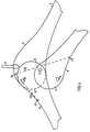
- Fig. 1 shows a schematic side view of a possible embodiment of a coat hanger according to the invention, without specifying whether the coat hanger is I-shaped or U-shaped in cross section.
- the coat hanger consists of an unmovable portion 1, comprising a wing 2, a hook 3, a first hinge half 4 which is unmovably connected with the unmovable portion 1 and a second hinge half 5 unmovably connected with a movable portion 6.
- the first hinge half 4 comprises two plastic discs, between which a disc-like second hinge portion 5 can slide, or the second hinge half 5 comprises two plastic discs between which the disc-like first hinge half 4 can slide.
- a point of rotation is provided off-centre at the underside of the hinge.
- the movable portion 6 is illustrated in two conditions, in a first, extended condition in which the coat hanger can carry a piece of clothing and in a second, folded condition in which the coat hanger can be inserted through a neck opening into a piece of clothing. Further, locking means 8 are indicated, which lock a coat hanger once it is in the extended condition. For the solidity of the coat hanger it is important that the locking means 8 are located closely to the top edge in order to be able to properly absorb the forces on the movable portion 6.
- the coat hangers are U-shaped or I-shaped in cross section.
- the cross section has to be brought back to the form described above.
- the hinge half having two discs
- the two sides of the U-profile at the hinge half enclosing the single disc have to taper toward each other and have in fact to form one whole, or at least have to be practically adjacent thereto. This is easily realised when injection moulding is used.
- Fig. 2A shows more detailed a schematic side view of a possible embodiment of a hinge in which the locking and the unlocking depends on the elasticity of the plastic from which the hinge is made.
- the first hinge half 4 here embodied as single disc, is provided at the point of rotation with two notches 7, one at each side of the disc, and the locking means with two bevelled notches 8, also one at each side of the disc.
- the second hinge half 5, which is in this case embodied as a double disc, is provided at the point of rotation with two openings 7a and at the place of the locking means with two openings 8a. It is immediately obvious that when the notches fall into the openings, the coat hanger is locked in the extended position.
- the coat hanger can be folded up.
- the notches 7 are put into the openings 7a by slightly bending the double disc open and then sliding the single disc between the double disc until the notches 7 fall into the openings 7a.
- Fig. 2B shows a more detailed schematic top view of the same hinge, with the first hinge half 4, second hinge half 5 tapering 9 out from the plate-like portion 10 of the I-profile.
- the notches 7 can be seen which, together with the openings 7a form the point of rotation, and the bevelled notches 8 which together with the openings 8a form the locking means.
- the notches 8 are bevelled in one direction, to allow a transition from a folded condition into an extended condition to proceed smoothly, due to the fact that the double disc is bent open gradually by the bevel of the notches 11. It goes without saying that the position of the notches and openings may be interchanged without altering the priciple of the workings.
- Fig. 3A shows a more detailed schematic side view of an alternative embodiment of the hinge, in which a locking or an unlocking depends on a translation of the movable portion in relation to the unmovable portion during the movement from the folded to the extended position or from the extended position to the folded position of the coat hanger.
- the first hinge half 4 being embodied here as a single disc, is at the point of rotation provided with two notches 11, one at each side of the disc, and at the place of the locking means with a recess 13.
- the second hinge half 5 which in this case is embodied as a double disc, each disc is at the point of rotation provided with an L-shaped opening 12, and at the locking means with a bar 14, connecting the insides of the double disc.
- the coat hanger can assume the folded condition.
- rod 14 will move along the outside of the first hinge half 4 with the notches 11 being in the bottom of the long legs of the L-shaped openings 12.
- the notches 11 translate upward and then into the short legs of the L-shaped openings 12 thereby locking the coat hanger.
- the notches 11 are again placed into the L-shaped openings 12 by slightly bending the double disc open and then sliding the single disc between until the notches 11 fall into the L-shaped openings 12.
- Fig. 3B shows a more detailed schematic top view of the same hinge, comprising the first hinge half 4, second hinge half 5, which again tapers from out from the plate-like portion 10 of the I-profile. Also visible are the notches 11, which together with the L-shaped opening 12 forms the point of rotation 7 and the rod 14, which together with the recess 13 forms the locking means 8. It goes without saying that notches 11, L-shaped openings 12, recess 13 and rod 14 can be arranged in other combinations. For example, the positions of recess 13 and rod 14 may be interchanged with L-shaped openings 12 then having to be positioned in mirror image in order to effectuate locking.
- Fig. 4 shows a schematic side view of a possible embodiment of a coat hanger according to the invention, in which spring means 15 are provided, which in this case are embodied as an elastic band fitted into two grooves 16,17.
- the spring means 15 keep the coat hanger in the folded condition, but on the other hand they assist in bringing the coat hanger into the extended position, thereby saving time.
Abstract
Description
When only the
Claims (6)
- A foldable plastic coat hanger which can assume at least an extended condition and a substantially folded condition, consisting of an unmovable portion (1) comprising a hook (3), a wing (2), a first hinge half (4) and first locking means (8), and a movable portion (6), comprising a wing, a second hinge half (5) equipped to engage the first hinge half (4), second locking means (8a), equipped to engage the first locking means (8) for locking the coat hanger in its extended condition, the first hinge half (4) comprising two disc-like plastic parts, between which the second hinge half (8a) comprising one disk-like plastic part is rotatable about a point of rotation or the second hinge half (5) comprising two disc-like plastic parts, between which the first hinge half (4) comprising one disk-like plastic part is rotatable about a point of rotation, characterized in that the point of rotation (7) is located off centre in the disk-like plastic parts and that the locking means (8,8a) are provided in the disk-like plastic parts, substantially diagonally to the point of rotation (7 ), such that the disc-like hinge halves (4,5) form at the upper side a substantially closed surface when in the extended, when in the folded, and in any intermediate condition.
- A foldable plastic coat hanger according to claim 1, characterized in that in the extended condition, the centres of the disc-like plastic parts substantially coincide at a point 1-3 cm from the centre of the coat hanger.
- A foldable plastic coat hanger according to claim 1, characterized in that the first locking means (8) are a depression in the unmovable portion and the second locking means are a projection (8a) on the movable portion, which projection in the extended condition falls into the depression, or that the first locking means (8) are a depression in the movable portion and the second locking means (8a) are a projection on the unmovable portion, which projection in the extended condition falls into the depression.
- A foldable plastic coat hanger according to claim 3, characterized in that a locking or unlocking depends on an elasticity of the plastic.
- A foldable plastic coat hanger according to claim 1, characterized in that a locking or an unlocking depends on a translation of the movable portion in relation to the unmovable portion while bringing the coat hanger from the folded condition into the extended condition or from the extended condition into the folded condition.
- A foldable plastic coat hanger according to claim 3 or 5, characterized in that the unmovable portion and the movable portion are injection-moulded pieces.
Applications Claiming Priority (3)
| Application Number | Priority Date | Filing Date | Title |
|---|---|---|---|
| NL1010283 | 1998-10-09 | ||
| NL1010283A NL1010283C2 (en) | 1998-10-09 | 1998-10-09 | Foldable plastic coat hanger. |
| PCT/NL1999/000486 WO2000021421A1 (en) | 1998-10-09 | 1999-07-29 | Foldable plastic coathanger |
Publications (2)
| Publication Number | Publication Date |
|---|---|
| EP1124471A1 EP1124471A1 (en) | 2001-08-22 |
| EP1124471B1 true EP1124471B1 (en) | 2003-06-04 |
Family
ID=19767947
Family Applications (1)
| Application Number | Title | Priority Date | Filing Date |
|---|---|---|---|
| EP99937107A Expired - Lifetime EP1124471B1 (en) | 1998-10-09 | 1999-07-29 | Foldable plastic coathanger |
Country Status (8)
| Country | Link |
|---|---|
| EP (1) | EP1124471B1 (en) |
| AT (1) | ATE241929T1 (en) |
| AU (1) | AU5199799A (en) |
| DE (1) | DE69908632T2 (en) |
| ES (1) | ES2201749T3 (en) |
| NL (1) | NL1010283C2 (en) |
| PT (1) | PT1124471E (en) |
| WO (1) | WO2000021421A1 (en) |
Families Citing this family (3)
| Publication number | Priority date | Publication date | Assignee | Title |
|---|---|---|---|---|
| NL1016462C2 (en) | 2000-10-23 | 2002-04-24 | Mainetti Pendy B V | Placing clothes on foldable hangers, uses machine to supply and unfold hangers, and operative to place clothes over folded hangers |
| GB2386548A (en) * | 2002-03-18 | 2003-09-24 | Robert John Iles | Folding garment hanger |
| FR2879909B1 (en) | 2004-12-29 | 2008-02-08 | Clenet Jacques Olivier | FOLDING CARRIER HANGER |
Family Cites Families (5)
| Publication number | Priority date | Publication date | Assignee | Title |
|---|---|---|---|---|
| FR783806A (en) * | 1934-03-29 | 1935-07-18 | Adjustable and foldable hanger | |
| US2232771A (en) | 1939-03-22 | 1941-02-25 | Isidore A Chaikin | Garment hanger |
| US2716513A (en) * | 1952-12-05 | 1955-08-30 | Braunstein Paul | Garment hanger |
| US2926823A (en) * | 1956-11-29 | 1960-03-01 | Weiser Morris | Garment hanger |
| DE19708943A1 (en) * | 1997-03-05 | 1998-09-17 | Johannsen Daniel | Coathanger of two-armed bow and fitted hook |
-
1998
- 1998-10-09 NL NL1010283A patent/NL1010283C2/en not_active IP Right Cessation
-
1999
- 1999-07-29 DE DE69908632T patent/DE69908632T2/en not_active Expired - Fee Related
- 1999-07-29 AT AT99937107T patent/ATE241929T1/en not_active IP Right Cessation
- 1999-07-29 AU AU51997/99A patent/AU5199799A/en not_active Abandoned
- 1999-07-29 EP EP99937107A patent/EP1124471B1/en not_active Expired - Lifetime
- 1999-07-29 WO PCT/NL1999/000486 patent/WO2000021421A1/en active IP Right Grant
- 1999-07-29 ES ES99937107T patent/ES2201749T3/en not_active Expired - Lifetime
- 1999-07-29 PT PT99937107T patent/PT1124471E/en unknown
Also Published As
| Publication number | Publication date |
|---|---|
| DE69908632D1 (en) | 2003-07-10 |
| EP1124471A1 (en) | 2001-08-22 |
| WO2000021421A1 (en) | 2000-04-20 |
| ATE241929T1 (en) | 2003-06-15 |
| NL1010283C2 (en) | 2000-04-11 |
| DE69908632T2 (en) | 2004-05-13 |
| ES2201749T3 (en) | 2004-03-16 |
| PT1124471E (en) | 2003-09-30 |
| AU5199799A (en) | 2000-05-01 |
Similar Documents
| Publication | Publication Date | Title |
|---|---|---|
| US6467658B1 (en) | Coordinate loop garment hanger | |
| US7055216B2 (en) | Magnetic hinge | |
| US6277021B1 (en) | Carrying hook for poultry | |
| US5042676A (en) | Handle mounting for containers | |
| EP1124471B1 (en) | Foldable plastic coathanger | |
| US10973301B2 (en) | Packaging device for a cosmetic product | |
| US4556191A (en) | Mold for the manufacture of shoe soles | |
| US5150874A (en) | Apparatus for mounting foldable branches to an artificial tree | |
| US2295494A (en) | Combined box and hinge construction | |
| JPH08308625A (en) | Improved case for glasses | |
| CA2047479A1 (en) | Folding knife | |
| US20030183666A1 (en) | Clothes hanger | |
| FI95680C (en) | Detachable plastic bottle box | |
| CN104832015B (en) | Support rocker for hanging window and hanging window | |
| EP0801197B1 (en) | Isothermal container having a double-hinged door | |
| KR20150009490A (en) | Sliding door of three interlock of hanger type | |
| JPS6426239U (en) | ||
| AU654448B2 (en) | A sliding partition containing rotatable louvres | |
| AU604579B2 (en) | Toilet seat assembly | |
| JPH082399Y2 (en) | Stepladder | |
| JPH0310204Y2 (en) | ||
| AU2002100249A4 (en) | A hanger for an article | |
| GB2406505A (en) | Folding garment hanger | |
| FR2586346A1 (en) | Hanger for narrow-necked garments | |
| GB2186020A (en) | Turning window arrangements |
Legal Events
| Date | Code | Title | Description |
|---|---|---|---|
| PUAI | Public reference made under article 153(3) epc to a published international application that has entered the european phase |
Free format text: ORIGINAL CODE: 0009012 |
|
| 17P | Request for examination filed |
Effective date: 20010511 |
|
| AK | Designated contracting states |
Kind code of ref document: A1 Designated state(s): AT BE CH CY DE DK ES FI FR GB GR IE IT LI LU MC NL PT SE |
|
| AX | Request for extension of the european patent |
Free format text: AL;LT;LV;MK;RO;SI |
|
| 17Q | First examination report despatched |
Effective date: 20011017 |
|
| GRAG | Despatch of communication of intention to grant |
Free format text: ORIGINAL CODE: EPIDOS AGRA |
|
| GRAG | Despatch of communication of intention to grant |
Free format text: ORIGINAL CODE: EPIDOS AGRA |
|
| GRAH | Despatch of communication of intention to grant a patent |
Free format text: ORIGINAL CODE: EPIDOS IGRA |
|
| GRAH | Despatch of communication of intention to grant a patent |
Free format text: ORIGINAL CODE: EPIDOS IGRA |
|
| GRAA | (expected) grant |
Free format text: ORIGINAL CODE: 0009210 |
|
| AK | Designated contracting states |
Designated state(s): AT BE CH CY DE DK ES FI FR GB GR IE IT LI LU MC NL PT SE |
|
| PG25 | Lapsed in a contracting state [announced via postgrant information from national office to epo] |
Ref country code: FI Free format text: LAPSE BECAUSE OF FAILURE TO SUBMIT A TRANSLATION OF THE DESCRIPTION OR TO PAY THE FEE WITHIN THE PRESCRIBED TIME-LIMIT Effective date: 20030604 Ref country code: AT Free format text: LAPSE BECAUSE OF FAILURE TO SUBMIT A TRANSLATION OF THE DESCRIPTION OR TO PAY THE FEE WITHIN THE PRESCRIBED TIME-LIMIT Effective date: 20030604 |
|
| REG | Reference to a national code |
Ref country code: GB Ref legal event code: FG4D |
|
| REG | Reference to a national code |
Ref country code: CH Ref legal event code: EP |
|
| REG | Reference to a national code |
Ref country code: IE Ref legal event code: FG4D |
|
| REF | Corresponds to: |
Ref document number: 69908632 Country of ref document: DE Date of ref document: 20030710 Kind code of ref document: P |
|
| REG | Reference to a national code |
Ref country code: CH Ref legal event code: NV Representative=s name: HEPP, WENGER & RYFFEL AG |
|
| PG25 | Lapsed in a contracting state [announced via postgrant information from national office to epo] |
Ref country code: LU Free format text: LAPSE BECAUSE OF NON-PAYMENT OF DUE FEES Effective date: 20030729 Ref country code: CY Free format text: LAPSE BECAUSE OF FAILURE TO SUBMIT A TRANSLATION OF THE DESCRIPTION OR TO PAY THE FEE WITHIN THE PRESCRIBED TIME-LIMIT Effective date: 20030729 |
|
| PG25 | Lapsed in a contracting state [announced via postgrant information from national office to epo] |
Ref country code: MC Free format text: LAPSE BECAUSE OF NON-PAYMENT OF DUE FEES Effective date: 20030731 |
|
| PG25 | Lapsed in a contracting state [announced via postgrant information from national office to epo] |
Ref country code: GR Free format text: LAPSE BECAUSE OF FAILURE TO SUBMIT A TRANSLATION OF THE DESCRIPTION OR TO PAY THE FEE WITHIN THE PRESCRIBED TIME-LIMIT Effective date: 20030904 Ref country code: DK Free format text: LAPSE BECAUSE OF FAILURE TO SUBMIT A TRANSLATION OF THE DESCRIPTION OR TO PAY THE FEE WITHIN THE PRESCRIBED TIME-LIMIT Effective date: 20030904 |
|
| REG | Reference to a national code |
Ref country code: SE Ref legal event code: TRGR |
|
| REG | Reference to a national code |
Ref country code: PT Ref legal event code: SC4A Free format text: AVAILABILITY OF NATIONAL TRANSLATION Effective date: 20030721 |
|
| LTIE | Lt: invalidation of european patent or patent extension |
Effective date: 20030604 |
|
| REG | Reference to a national code |
Ref country code: ES Ref legal event code: FG2A Ref document number: 2201749 Country of ref document: ES Kind code of ref document: T3 |
|
| ET | Fr: translation filed | ||
| PLBE | No opposition filed within time limit |
Free format text: ORIGINAL CODE: 0009261 |
|
| STAA | Information on the status of an ep patent application or granted ep patent |
Free format text: STATUS: NO OPPOSITION FILED WITHIN TIME LIMIT |
|
| 26N | No opposition filed |
Effective date: 20040305 |
|
| PGFP | Annual fee paid to national office [announced via postgrant information from national office to epo] |
Ref country code: IE Payment date: 20040630 Year of fee payment: 6 |
|
| PGFP | Annual fee paid to national office [announced via postgrant information from national office to epo] |
Ref country code: PT Payment date: 20040708 Year of fee payment: 6 |
|
| PGFP | Annual fee paid to national office [announced via postgrant information from national office to epo] |
Ref country code: NL Payment date: 20040715 Year of fee payment: 6 |
|
| PGFP | Annual fee paid to national office [announced via postgrant information from national office to epo] |
Ref country code: BE Payment date: 20040716 Year of fee payment: 6 |
|
| PGFP | Annual fee paid to national office [announced via postgrant information from national office to epo] |
Ref country code: SE Payment date: 20040719 Year of fee payment: 6 Ref country code: GB Payment date: 20040719 Year of fee payment: 6 |
|
| PGFP | Annual fee paid to national office [announced via postgrant information from national office to epo] |
Ref country code: CH Payment date: 20040721 Year of fee payment: 6 |
|
| PGFP | Annual fee paid to national office [announced via postgrant information from national office to epo] |
Ref country code: FR Payment date: 20040722 Year of fee payment: 6 |
|
| PGFP | Annual fee paid to national office [announced via postgrant information from national office to epo] |
Ref country code: ES Payment date: 20040730 Year of fee payment: 6 Ref country code: DE Payment date: 20040730 Year of fee payment: 6 |
|
| PG25 | Lapsed in a contracting state [announced via postgrant information from national office to epo] |
Ref country code: IT Free format text: LAPSE BECAUSE OF NON-PAYMENT OF DUE FEES Effective date: 20050729 Ref country code: GB Free format text: LAPSE BECAUSE OF NON-PAYMENT OF DUE FEES Effective date: 20050729 |
|
| PG25 | Lapsed in a contracting state [announced via postgrant information from national office to epo] |
Ref country code: SE Free format text: LAPSE BECAUSE OF NON-PAYMENT OF DUE FEES Effective date: 20050730 Ref country code: ES Free format text: LAPSE BECAUSE OF NON-PAYMENT OF DUE FEES Effective date: 20050730 |
|
| PG25 | Lapsed in a contracting state [announced via postgrant information from national office to epo] |
Ref country code: LI Free format text: LAPSE BECAUSE OF NON-PAYMENT OF DUE FEES Effective date: 20050731 Ref country code: CH Free format text: LAPSE BECAUSE OF NON-PAYMENT OF DUE FEES Effective date: 20050731 Ref country code: BE Free format text: LAPSE BECAUSE OF NON-PAYMENT OF DUE FEES Effective date: 20050731 |
|
| PG25 | Lapsed in a contracting state [announced via postgrant information from national office to epo] |
Ref country code: PT Free format text: LAPSE BECAUSE OF NON-PAYMENT OF DUE FEES Effective date: 20060130 |
|
| PG25 | Lapsed in a contracting state [announced via postgrant information from national office to epo] |
Ref country code: NL Free format text: LAPSE BECAUSE OF NON-PAYMENT OF DUE FEES Effective date: 20060201 Ref country code: DE Free format text: LAPSE BECAUSE OF NON-PAYMENT OF DUE FEES Effective date: 20060201 |
|
| REG | Reference to a national code |
Ref country code: CH Ref legal event code: PL |
|
| EUG | Se: european patent has lapsed | ||
| GBPC | Gb: european patent ceased through non-payment of renewal fee |
Effective date: 20050729 |
|
| PG25 | Lapsed in a contracting state [announced via postgrant information from national office to epo] |
Ref country code: FR Free format text: LAPSE BECAUSE OF NON-PAYMENT OF DUE FEES Effective date: 20060331 |
|
| NLV4 | Nl: lapsed or anulled due to non-payment of the annual fee |
Effective date: 20060201 |
|
| REG | Reference to a national code |
Ref country code: IE Ref legal event code: MM4A |
|
| REG | Reference to a national code |
Ref country code: FR Ref legal event code: ST Effective date: 20060331 |
|
| REG | Reference to a national code |
Ref country code: ES Ref legal event code: FD2A Effective date: 20050730 |
|
| BERE | Be: lapsed |
Owner name: *DE GROOT JAN CORNELIS Effective date: 20050731 |