EP1124402A2 - Automatische Verbindungsvariant-Ermittlung und Protokol-Konfiguration - Google Patents
Automatische Verbindungsvariant-Ermittlung und Protokol-Konfiguration Download PDFInfo
- Publication number
- EP1124402A2 EP1124402A2 EP01301081A EP01301081A EP1124402A2 EP 1124402 A2 EP1124402 A2 EP 1124402A2 EP 01301081 A EP01301081 A EP 01301081A EP 01301081 A EP01301081 A EP 01301081A EP 1124402 A2 EP1124402 A2 EP 1124402A2
- Authority
- EP
- European Patent Office
- Prior art keywords
- link
- type
- llc
- test
- cpe
- Prior art date
- Legal status (The legal status is an assumption and is not a legal conclusion. Google has not performed a legal analysis and makes no representation as to the accuracy of the status listed.)
- Granted
Links
Images


Classifications
-
- H—ELECTRICITY
- H04—ELECTRIC COMMUNICATION TECHNIQUE
- H04Q—SELECTING
- H04Q11/00—Selecting arrangements for multiplex systems
- H04Q11/04—Selecting arrangements for multiplex systems for time-division multiplexing
- H04Q11/0428—Integrated services digital network, i.e. systems for transmission of different types of digitised signals, e.g. speech, data, telecentral, television signals
- H04Q11/0478—Provisions for broadband connections
-
- H—ELECTRICITY
- H04—ELECTRIC COMMUNICATION TECHNIQUE
- H04L—TRANSMISSION OF DIGITAL INFORMATION, e.g. TELEGRAPHIC COMMUNICATION
- H04L12/00—Data switching networks
- H04L12/54—Store-and-forward switching systems
- H04L12/56—Packet switching systems
- H04L12/5601—Transfer mode dependent, e.g. ATM
- H04L2012/5603—Access techniques
-
- H—ELECTRICITY
- H04—ELECTRIC COMMUNICATION TECHNIQUE
- H04L—TRANSMISSION OF DIGITAL INFORMATION, e.g. TELEGRAPHIC COMMUNICATION
- H04L12/00—Data switching networks
- H04L12/54—Store-and-forward switching systems
- H04L12/56—Packet switching systems
- H04L12/5601—Transfer mode dependent, e.g. ATM
- H04L2012/5614—User Network Interface
- H04L2012/5616—Terminal equipment, e.g. codecs, synch.
-
- H—ELECTRICITY
- H04—ELECTRIC COMMUNICATION TECHNIQUE
- H04L—TRANSMISSION OF DIGITAL INFORMATION, e.g. TELEGRAPHIC COMMUNICATION
- H04L12/00—Data switching networks
- H04L12/54—Store-and-forward switching systems
- H04L12/56—Packet switching systems
- H04L12/5601—Transfer mode dependent, e.g. ATM
- H04L2012/5638—Services, e.g. multimedia, GOS, QOS
- H04L2012/5665—Interaction of ATM with other protocols
Definitions
- the present invention relates generally to communication networks, such as Internet Protocol (IP) networks including asynchronous transfer mode (ATM) connections or digital subscriber line (DSL) connections, and more particularly to customer premises equipment (CPE) or other devices that attach to such a network, e.g., CPE that attaches to the network via a DSL that transports Internet Protocol (IP) datagrams via ATM cells or other formats.
- IP Internet Protocol
- ATM synchronous transfer mode
- DSL digital subscriber line
- CPE customer premises equipment
- IP Internet Protocol
- IP communications service over ATM has been defined by the Internet Engineering Task Force (IETF) in several Request for Comments (RFCs) that describe different ways to encapsulate other protocols in ATM cells.
- RFC 1483 entitled “Multi-protocol encapsulation over ATM,” which is incorporated by reference herein.
- CPE Cisco Advanced Polymer
- link variants or simply “variants.”
- IP communications is intended to include any type of IP packets, including IP in an unencapsulated form, or encapsulated in Ethernet, point-to-point protocol (PPP), logical link control (LLC), etc.
- the second approach requires the customer to purchase CPE that is dedicated to a specific link variant. Although this avoids the need for the customer to make adjustments to the CPE, it can present substantial difficulties in situations in which the type of link may change, e.g., if the customer changes Internet Service Provider (ISP). It is clearly undesirable for the customer to be required to replace the CPE in such situations.
- ISP Internet Service Provider
- the third approach is to have a CPE vendor, or its agent, visit the customer site in person and perform a link configuration operation using conventional administrative techniques.
- This approach although it can ensure an accurate configuration, is unduly complex and may be prohibitively expensive for the CPE vendor, network access provider and/or customer.
- the invention provides techniques for automated link variant determination and configuration of customer premises equipment (CPE) or other network devices.
- CPE customer premises equipment
- the invention solves the above-noted problems associated with conventional link variant determination and CPE configuration by providing an automated system that detects the link type, and then activates a protocol entity in the CPE or other network device that is appropriate to the detected link type.
- the CPE or other network device may include a processing element that operates to implement selection of an appropriate interface or other protocol entity based on the link variant determination.
- an autosensor or other communication system processing device determines which of a number of available link variants is required for a particular communication link that couples the CPE or other device to a network.
- the autosensor examines responses to messages sent over the link in order to determine one or more link variants associated therewith.
- the CPE or other device is then automatically configured to support the determined link variant(s), e.g., by activation of an appropriate protocol entity in the CPE or other device.
- the CPE may be coupled to a network via an Asynchronous Transfer Mode (ATM) virtual circuit (VC) established over a digital subscriber line (DSL).
- ATM Asynchronous Transfer Mode
- VC virtual circuit
- DSL digital subscriber line
- multiple protocols may be encapsulated within the ATM cells, with each of the multiple protocols corresponding to a link variant.
- the CPE in this case may correspond to an ADSL termination unit-receive (ATU-R) device, or other type of gateway.
- ATU-R ADSL termination unit-receive
- the determined link type in the illustrative embodiment may include, e.g., one or more of a logical link control (LLC), a point-to-point protocol (PPP), an LLC-PPP, an Internet protocol (IP), an LLC-IP protocol, an Ethernet protocol, and an LLC-Ethernet protocol.
- LLC logical link control
- PPP point-to-point protocol
- IP Internet protocol
- IP Internet protocol
- LLC-IP protocol an Ethernet protocol
- LLC-Ethernet protocol LLC-Ethernet protocol.
- a first test is applied to determine if the link is an LLC-type link. If the link is not an LLC-type link, at least one additional test of a first type is applied, e.g., a test to determine if the link is a PPP link. If the link is an LLC-type link, at least one additional test of a second type is applied, e.g., a test to determine a particular type of encapsulation for the LLC-type link.
- the invention provides automated link variant determination and corresponding CPE configuration which avoids the problems associated with the above-described conventional approaches.
- the invention can also be implemented in other types of communication systems including, for example, Frame Relay systems, IP systems, or in conjunction with any other type of encapsulation technique.
- the invention can be used with other types of transport mechanisms and communication links.
- the invention is applicable to other types of devices attached to or otherwise associated with a network communication link.
- the invention may be implemented in a network server, so as to provide appropriate link variant determination and configuration to allow the server to communicate with another device over a particular fixed type of communication link.
- FIG. 1 is a block diagram of an exemplary communication system in which the invention may be implemented.
- FIG. 2 is a more detailed block diagram showing a portion of the FIG. 1 communication system relating to automated link variant determination in accordance with the invention.
- FIG. 3 is a state diagram of an automated variant determination process in accordance with an illustrative embodiment of the invention.
- FIGS. 4 and 5 show examples of system activation and virtual circuit (VC) activation state machines in accordance with the invention.
- the present invention will be illustrated below in conjunction with an exemplary communication system which provides connections between a local area network (LAN) and one or more external networks via a gateway.
- LAN local area network
- IP Internet Protocol
- the disclosed techniques are suitable for use with a wide variety of other types of systems including, for example, Frame Relay systems and IP systems, and with any desired type of communication medium, including asymmetric digital subscriber line (ADSL), synchronous optical network (Sonet)/synchronous digital hierarchy (SDH), wireless networks, etc.
- the term "local network” as used herein in intended to include any type of network which may be interfaced via a gateway device to one or more external network elements.
- a local network in accordance with the invention may therefore include, e.g., a LAN, wide area network (WAN), metropolitan area network (MAN), extranet, or intranet, as well as portions or combinations of these and other networks.
- the invention may be used with any desired type of transport mechanism, communication link, or set of protocol variants.
- the present invention solves the above-described problems associated with configuration of customer premises equipment (CPE) or other network devices to support a particular one of a set of available link variants.
- An illustrative embodiment of the invention provides a system-driven process that detects the link type associated with the CPE, and then activates a protocol entity in the CPE that is appropriate to the link type. As will be described in greater detail below, this may be accomplished, e.g., by defining a message set for all link variant options, where each option is determined to have at least one message that, by specification requirement, demands a response.
- such a response may require the return of data as an appropriate reply to a mandatory request for information.
- there may be no such mandatory requests defined for the protocol so other types of responses may be defined.
- an error condition may be generated which mandates that a condition notification datagram be sent to the originator of the error condition.
- the invention in the illustrative embodiment thus issues a series of messages, and compares the resulting responses to the expected responses associated with each of the link variants.
- the CPE is thereby able to determine the correct link variant protocol and communicate successfully with the network without user or technician intervention.
- the system will automatically reconfigure in the event of a network equipment upgrade, a change from a current Internet service provider (ISP) to one which supports different varieties of equipment, or in other similar situations.
- ISP Internet service provider
- FIG. 1 shows a portion of a communication system 100 in accordance with an illustrative embodiment of the invention.
- the system 100 includes a LAN 102. Coupled to the LAN 102 are a plurality of personal computers designated PC-1, PC-2, PC-3,... PC-N, a printer 104 and a local file server 106. Also coupled to the LAN 102 is gateway 110, which may be, e.g., an ADSL termination unit-receive (ATU-R) device, as described in ANSI standard T1.413, which is incorporated by reference herein.
- ATU-R ADSL termination unit-receive
- the gateway 110 and the devices coupled thereto are an example of CPE which may operate in accordance with an automated link variant determination process of the present invention. It should be understood, however, that the invention may be utilized in conjunction with many other types of CPE, as well as in other types of devices that may be coupled to a network.
- a "device coupled to a network” is intended to include a device or set of devices that are also considered elements of the network itself.
- the gateway 110 communicates via an ADSL link to a DSL access multiplexer (DSLAM) 112.
- DSLAM 112 provides connections between the gateway 110 and a number of external networks, which in this illustrative embodiment include a public switched telephone network (PSTN) 114, and an asynchronous transfer mode (ATM) network 116 which includes a remote access server (RAS) 118.
- PSTN public switched telephone network
- ATM asynchronous transfer mode
- RAS remote access server
- the RAS 118 may be, e.g., a broadband RAS.
- Endpoints of the LAN 102 may be assigned Internet Protocol (IP) addresses by the RAS 118 in accordance with the well-known Dynamic Host Configuration Protocol (DHCP).
- IP Internet Protocol
- DHCP Dynamic Host Configuration Protocol
- IP addresses may be assigned to DHCP, such that each computer or other device on the local network can have its Transmission Control Protocol (TCP)/IP software configured to request an IP address from a remote DHCP server.
- TCP Transmission Control Protocol
- IP software configured to request an IP address from a remote DHCP server.
- the request and grant process uses a lease concept with a controllable time period.
- ATM Forum "ATM User-Network Interface Specification,” Version 3.1, September, 1994
- Martin de Prycker "Asynchronous Transfer Mode: Solution for Broadband ISDN,” Ellis Horwood, New York, 1993, both of which are incorporated by reference herein.
- FIG. 2 shows a portion 200 of the system 100 in greater detail.
- the portion 200 may be implemented, e.g., primarily in the gateway 110, primarily in the DSLAM 112, partly in the gateway 110 and partly in the DSLAM 112, in the RAS 118, or in one or more other elements of the system 100.
- the link variant determination and protocol configuration techniques of the present invention is thus not restricted to use in CPE or in any other particular type of network device, and may be distributed across multiple devices. It may be assumed, for illustrative purposes, that the portion 200 is implemented primarily in an ATU-R device corresponding to the gateway 110.
- the portion 200 includes a configuration manager 202 coupled to system database 204, a transport manager 206, and a state machine complex 208.
- the configuration manager 202 controls the operation of elements 204, 206 and 208, and interfaces with a configuration application 203 which may be implemented in a personal computer (PC) associated with a user of the CPE or other network device, or may be implemented in another device, such as a remote element management system (EMS), associated with the communication system 100.
- the configuration application 203 may be used, e.g., to provide an initial VPI/VCI (virtual path indicator/virtual channel indicator) for use by the CPE or other network device.
- the transport manager 206 controls both user communications and gateway communications as shown.
- the state machine complex 208 includes a system activation state machine 210 and a number of virtual circuit (VC) activation state machines denoted 212-1, 212-2 and 212-3.
- VC virtual circuit
- An example of a system activation state machine is shown in greater detail in FIG. 4.
- An example of a VC activation state machine is shown in greater detail in FIG. 5.
- three VC activation state machines are shown in the state machine complex 208 of FIG. 2, this is by way of example only, and other embodiments may include more or less than three VC activation state machines.
- the portion 200 of the system 100 further includes an autosensor 215 which controls selection of a particular one of a set of logical access interfaces 220.
- Each of the logical access interfaces corresponds to a particular link variant, and the autosensor 215 is configured to perform a sequence of tests to determine automatically which link variant is required for communication with a given piece of CPE. These tests will be described in greater detail below in conjunction with the state diagram of FIG. 3.
- the set of logical access interfaces 220 includes a logical link control (LLC) interface, a point-to-point protocol (PPP) interface, an LLC-PPP interface, an Internet protocol (IP) interface, an LLC-IP interface, an Ethernet interface, and an LLC-Ethernet interface. As previously noted, each of these interfaces corresponds to a particular link variant.
- the PPP and LLC-PPP interfaces are coupled to a PPP driver 222.
- the LLC, IP, LLC-IP, Ethernet and LLC-Ethernet interfaces are coupled to a 1483 driver 224 which operates in accordance with the above-noted RFC 1483 entitled "Multi-protocol encapsulation over ATM.”
- a particular one of the interfaces is activated or otherwise selected for use based on result of the link variant determination to be described in greater detail below.
- Both the PPP driver 222 and the 1483 driver 224 are coupled to an ATM Adaptation Layer 5 (AAL5) device 225 which provides an interface to an ATM network.
- AAL5 device 225 provides an interface to an ATM network.
- ITU -T International Telecommunication Union-Telecommunication Standardization Sector
- Series I Integrated Services Digital Network
- Overall Network Aspects and Functions-Protocol Layer Requirements B-ISDN ATM Adaptation Layer Specification, Type 5 AAL, August 1996, which is incorporated by reference herein.
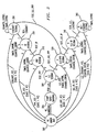
- FIG. 3 is a state diagram of an automated variant determination process that is implemented in the autosensor 215 of FIG. 2 in accordance with the invention.
- VC virtual circuit
- Case 1 the name of the variant
- PDU protocol data unit
- Each of the variants corresponds to one of the logical access interfaces in the set of interfaces 220 of FIG. 2.
- the invention does not require the use of these specific variants.
- a given set of variants used in conjunction with the invention may therefore include additional variants not shown, only a subset of the variants shown, or a completely different set of variants.
- the autosensing process as implemented in the state diagram of FIG. 3 determines for a given VC which of the above link variants, i.e., which of Cases 1 through 6, is applicable.
- the state diagram includes a VC Administration Initiation state 302, a Start Autosensing state 304, an LLC Testing state 306, a PPP testing state 310, an LLC-PPP Testing state 320, an IP Testing state 330, an LLC-IP Testing state 340, an Ethernet Testing state 350, and an LLC-Ethernet Testing state 360.
- each of the states 306, 310, 320, 330, 340, 350 and 360 is a particular test, an identifier of which is shown in a given state diagram above the corresponding state name. More particularly, associated with states 306, 310, 320 330, 340, 350 and 360 are tests denoted Test A, Test 1, Test 2, Test 3, Test 4, Test 5 and Test 6, respectively. Each of these tests is described in greater detail below, and generally involves sending one or more designated messages, and examining subsequent received datagrams.
- the state diagram indicates that the corresponding process starts in the VC Administration Initialization state 302.
- Generation of a VC_CONFIGURE indicator transitions the system to state 304 which starts the autosensing process.
- Generation of a TEST_LLC indicator transitions the system to state 306 for performance of Test A. If Test A fails, a TEST_PPP indicator is generated and the system transitions to state 310 to perform Test 1. If Test A passes, a TEST_LLC_PPP indicator is generated and the system transitions to state 320 to perform Test 2.
- Test A For each of Test A, Test 1, Test 2, Test 3 and Test 4, it is assumed the process remains in the corresponding state until either the test passes or the counter expires. If the counter expires without the test being passed, an indicator associated with performance of the next test in the sequence is generated prior to or in conjunction with a transition to the state which performs the next test.
- a COUNTER_EXPIRE indicator for each of states 306, 310, 320, 330 and 340 indicates that the process remains in the corresponding state until the next test indicator is generated and the transition to the next state occurs.
- Test 1 in state 310 passes, the VC is identified as a Case 1 VC, a PPP_YES indicator is generated, and the system returns to state 302. If Test 1 fails, a TEST_IP indicator is generated, and the system transitions to state 330 to perform Test 3. The system may remain in state 310 if a timer expiration indicator TIMER_EXPIRE or a counter expiration indicator COUNTER_EXPIRE is generated.
- Test 3 in state 330 passes, the VC is identified as a Case 3 VC, an IP_YES indicator is generated, and the system returns to state 302. If Test 3 fails, a TEST_ETHERNET indicator is generated, and the system transitions to state 350 to perform Test 5. The system may remain in state 330 if either of the TIMER_EXPIRE or COUNTER_EXPIRE indicators are generated.
- Test 5 in state 350 passes, the VC is identified as a Case 5 VC, an ETHERNET_YES indicator is generated, and the system returns to state 302. If Test 5 does not pass, the system transitions to state 320 upon generation of a TEST_LLC_PPP indicator. The system may remain in state 350 if either of the TIMER_EXPIRE or COUNTER_EXPIRE indicators are generated.
- Test 2 in state 320 passes, the VC is identified as a Case 2 VC, an LLC_PPP_YES indicator is generated, and the system returns to state 302. If Test 2 fails, a TEST_LLC_IP indicator is generated, and the system transitions to state 340 to perform Test 4. The system may remain in state 320 if either the TIMER_EXPIRE or COUNTER_EXPIRE indicators are generated.
- Test 4 in state 340 passes, the VC is identified as a Case 4 VC, an LLC_IP_YES indicator is generated, and the system returns to state 302. It should be understood that, in other embodiments, additional testing for further protocols could also be performed upon passage of Test 4. If Test 4 fails, a TEST_LLC_ETHERNET indicator is generated, and the system transitions to state 360 to perform Test 6. The system may remain in state 340 if either of the TIMER_EXPIRE or COUNTER_EXPIRE indicators are generated.
- Test 6 in state 360 passes, the VC is identified as a Case 6 VC, an LLC_ETHERNET_YES indicator is generated, and the system returns to state 302. If Test 6 does not pass, the system transitions to state 302 upon expiration of the counter, with the corresponding generation of a COUNTER_EXPIRE indicator.
- the autosensing process corresponding to the state diagram of FIG. 3 will now be described in greater detail.
- the process in the illustrative embodiment includes the following steps:
- Test A Check if VC uses LLC encapsulation
- Test A is passed if the subsequent received datagrams include the following octets:
- Test A fails if no subsequent received datagrams meet the pass criteria within boundaries set by the timer and counter.
- Test 1 Check if VC multiplexed PPP
- LCP refers to Link Control Protocol
- MRU refers to Maximum Receive Unit
- Test 1 is passed if the first 4 octets are as follows:
- Test 1 fails if no subsequent received datagrams meet the pass criteria within the boundaries set by the timer and counter.
- Test 2 Check if LLC encapsulated PPP
- Send LLC encapsulated PPP LCP Configure-Request as follows and start timer/initialize counter: Field Sub-Field Value No. of octets LLC header DSAP 0xFE (routed OSI PDU) 1 SSAP 0xFE (routed OSI PDU) 1 Control 0x03 (UI) 1 NLPID - 0xCF (PPP) 1 PPP Protocol Identifier - 0xC0-21 (LCP) 2 PPP Information (LCP Packet here) Code 1 (Configure-Request) 1 Identifier used for matching requests and replies 1 Length length of LCP packet 2 Data contains Configuration Options 0 or more PPP Padding - padding out to MRU as needed to pad out to MRU
- OSI PDU refers to the Open Systems Interconnect Protocol Data Unit
- UI refers to Unnumbered Information
- Test 2 is passed if the first 8 octets are as follows:
- Test 2 fails if no subsequent received datagrams meet the pass criteria within the boundaries set by the timer and counter.
- Test 3 Check if VC multiplexed IP
- ICMP refers to Internet Control Message Protocol.
- Test 3 is passed if the octets are as follows, and the identifier and sequence number match:
- Test 3 fails if no subsequent received datagrams meet the pass criteria within the boundaries set by the timer and counter.
- Test 4 Check if LLC encapsulated IP
- PID refers to Protocol Identifier
- OUI is a sub-field of the SNAP header as defined in ANSI/IEEE Standard 802.2.
- Test 4 is passed if the octets are as follows, and the identifier and sequence number match:
- Test 4 fails if no subsequent received datagrams meet the pass criteria within boundaries set by the timer and counter.
- Test 5 Check if VC multiplexed bridged Ethernet/802.3
- FCS refers to Frame Check Sequence.
- Test 5 is passed if the octets are as follows:
- Test 5 fails if no subsequent received datagrams meet the pass criteria within boundaries set by the timer and counter.
- Test 6 Check if LLC encapsulated Ethernet
- Test 6 is passed if the octets are as follows:
- Test 6 fails if no subsequent received datagrams meet the pass criteria within the boundaries set by the timer and counter.
- FIG. 4 shows a state diagram for an exemplary system activation state machine 210 of FIG. 2.
- the state diagram includes an Off state 402, a System Initialization state 404, a Local Upgrade state 406, a VC Activation state 408, and a Gateway Active state 410.
- the system is not powered.
- the system transitions to state 404.
- an upgrade may be initialized, resulting in transitions to or from state 406.
- the system from state 404 can transition directly to a VC Activation state 408.
- VC state machines can be initialized, e.g., in accordance with a state diagram as will be described below in conjunction with FIG. 5.
- the system from state 404 can also generate a READY indicator, which causes a transition to the Gateway Active state 410.
- the system can initializes VC state machines, e.g., in accordance with the FIG. 5 state diagram. This initialization may involve one or more ATM VCs for which IP communications exist.
- IP communications as used herein is broadly defined as any type of IP packets, including IP in an unencapsulated form, or encapsulated in Ethernet, PPP, LLC, etc.
- the system returns from states 408 or 410 to state 404 if an ALL_IP_VC_DOWN indicator is generated, indicating that there are no active VCs.
- FIG. 5 shows a state diagram for an exemplary VC activation state machine 212-1, 212-2 or 212-3 of FIG. 2.
- the state diagram includes a Null state 502, a VC Active state 302, and the VC Administration Initiation state 302 previously described in conjunction with FIG. 3.
- generation of an INITIALIZE_STATE_MACHINE indicator coincides with a transition to the VC Administration Initialization state 302.
- the previously-described autosensing procedures are carried out in order to determine the particular link type required by the CPE.
- the system transitions to the VC Active state 504, and performs periodic maintenance procedures while in that state.
- Generation of a VC_DOWN indicator will cause a transition from state 504 back to the Null state 502.
- generation of a CARRIED_PROTOCOL_DOWN indicator will cause a transition back to state 302.
- the CPE or other network device can be configured to support the link variant(s), e.g., by activating appropriate protocol entities in the CPE or other network device. For example, a particular interface can be selected for the given VC from among a set of available link variant interfaces in the CPE or other network device, in accordance with the determined link variant for that VC.
- the present invention may also be implemented in other types of devices attached to or otherwise associated with a network communication link.
- the invention may be implemented in a network server, so as to provide appropriate link variant determination and configuration to allow the server to communicate with another device over a particular type of communication link.
- the other device may be CPE having a fixed link variant requirement.
- processing element as used herein is intended to include any arrangement of one or more processors or other processing devices configured to provide autosensing and configuration functions in the manner described above, such as, e.g., an autosensor, a gateway, a RAS, a DSLAM, or one or more other elements of the system illustrated in FIGS. 1 and 2, as well as portions or combinations of such elements.
- the invention can be implemented in whole or in part in software stored on a machine-readable medium, e.g., an optical or magnetic disk, a disk-based storage device, an electronic memory, etc., and executed by a processor associated with a gateway or other similar element or set of elements of a communication system.
- a machine-readable medium e.g., an optical or magnetic disk, a disk-based storage device, an electronic memory, etc.
Landscapes
- Engineering & Computer Science (AREA)
- Computer Networks & Wireless Communication (AREA)
- Data Exchanges In Wide-Area Networks (AREA)
- Communication Control (AREA)
Applications Claiming Priority (2)
| Application Number | Priority Date | Filing Date | Title |
|---|---|---|---|
| US09/503,042 US6975597B1 (en) | 2000-02-11 | 2000-02-11 | Automated link variant determination and protocol configuration for customer premises equipment and other network devices |
| US503042 | 2000-02-11 |
Publications (3)
| Publication Number | Publication Date |
|---|---|
| EP1124402A2 true EP1124402A2 (de) | 2001-08-16 |
| EP1124402A3 EP1124402A3 (de) | 2004-03-24 |
| EP1124402B1 EP1124402B1 (de) | 2011-03-30 |
Family
ID=24000528
Family Applications (1)
| Application Number | Title | Priority Date | Filing Date |
|---|---|---|---|
| EP01301081A Expired - Lifetime EP1124402B1 (de) | 2000-02-11 | 2001-02-07 | Automatische Verbindungsvariant-Ermittlung und Protokol-Konfiguration |
Country Status (5)
| Country | Link |
|---|---|
| US (1) | US6975597B1 (de) |
| EP (1) | EP1124402B1 (de) |
| JP (1) | JP4159753B2 (de) |
| CA (1) | CA2332734C (de) |
| DE (1) | DE60144306D1 (de) |
Cited By (3)
| Publication number | Priority date | Publication date | Assignee | Title |
|---|---|---|---|---|
| US6778505B1 (en) * | 2000-01-03 | 2004-08-17 | Agere Systems Inc. | DSL automatic protocol detection system |
| WO2005022859A3 (en) * | 2003-08-21 | 2005-05-26 | Intel Corp | Communication protocol determination |
| WO2007093098A1 (en) | 2006-02-14 | 2007-08-23 | Huawei Technologies Co., Ltd. | A method for transmitting subscriber line layer 2 encapsulation mode to broadband access server |
Families Citing this family (15)
| Publication number | Priority date | Publication date | Assignee | Title |
|---|---|---|---|---|
| US6993048B1 (en) * | 2000-07-31 | 2006-01-31 | Cisco Technology, Inc. | ATM permanent virtual circuit and layer 3 auto-configuration for digital subscriber line customer premises equipment |
| AU2000275015A1 (en) * | 2000-09-29 | 2002-04-08 | Eicon Technology Corporation | Auto encapsulation detection |
| US7243154B2 (en) * | 2002-06-27 | 2007-07-10 | Intel Corporation | Dynamically adaptable communications processor architecture and associated methods |
| US7489693B2 (en) * | 2002-09-18 | 2009-02-10 | Conexant Systems, Inc. | Method and apparatus for automatically detecting virtual circuit settings and encapsulation types in a DSL network |
| US7421483B1 (en) * | 2004-02-02 | 2008-09-02 | Juniper Networks, Inc. | Autodiscovery and self configuration of customer premise equipment |
| US7499408B1 (en) * | 2004-03-23 | 2009-03-03 | Cisco Technology, Inc. | Method and system for establishing a communications connection |
| US20050243729A1 (en) * | 2004-04-16 | 2005-11-03 | Apparent Networks, Inc. | Method and apparatus for automating and scaling active probing-based IP network performance monitoring and diagnosis |
| US7751339B2 (en) | 2006-05-19 | 2010-07-06 | Cisco Technology, Inc. | Method and apparatus for simply configuring a subscriber appliance for performing a service controlled by a separate service provider |
| US20080037563A1 (en) * | 2006-08-10 | 2008-02-14 | Bernard Marc R | Method and apparatus for automatically detecting and configuring service ports of an optical network terminal (ONT) |
| EP2169980A1 (de) * | 2008-09-30 | 2010-03-31 | BRITISH TELECOMMUNICATIONS public limited company | Dynamische Leitungsverwaltung |
| EP2209324A1 (de) * | 2009-01-15 | 2010-07-21 | BRITISH TELECOMMUNICATIONS public limited company | Verwaltung von Telekommunikationsverbindungen |
| EP2237478A1 (de) | 2009-03-31 | 2010-10-06 | BRITISH TELECOMMUNICATIONS public limited company | Dynamische Linienverwaltung |
| WO2012015817A2 (en) * | 2010-07-28 | 2012-02-02 | Aware Inc | Adjusting controls at the physical layer to control link quality at higher layers |
| CN106657434B (zh) * | 2016-11-24 | 2019-12-06 | 新华三信息技术有限公司 | 一种ip地址的查看方法和装置 |
| CN110261701B (zh) * | 2019-06-27 | 2021-08-13 | 西安西拓电气股份有限公司 | 电力设备的配置方法、装置及系统 |
Family Cites Families (18)
| Publication number | Priority date | Publication date | Assignee | Title |
|---|---|---|---|---|
| JP2802088B2 (ja) | 1989-02-06 | 1998-09-21 | 株式会社日立製作所 | プロトコル選択切替方法 |
| JPH04120931A (ja) | 1990-09-12 | 1992-04-21 | Mitsubishi Electric Corp | マルチプロトコル通信制御方式 |
| EP0596648A1 (de) | 1992-11-02 | 1994-05-11 | National Semiconductor Corporation | Erkennung du Fähigkeiten eines Netzendpunkts |
| US5497460A (en) * | 1994-06-20 | 1996-03-05 | International Business Machines Corporation | System and method for determining network connectivity |
| US5671251A (en) | 1995-02-28 | 1997-09-23 | Motorola, Inc. | Apparatus and method for a data communications device to selectively operate as an analog modem, as a digital modem, and as a terminal adapter |
| US5574722A (en) * | 1995-03-21 | 1996-11-12 | Bay Networks, Inc. | Protocol independent switch |
| US6122287A (en) | 1996-02-09 | 2000-09-19 | Microcom Systems, Inc. | Method and apparatus for detecting switched network protocols |
| US5751796A (en) | 1996-06-21 | 1998-05-12 | Paradyne Corporation | Rapid startup protocol for communication between a plurality of modems |
| JPH1141317A (ja) | 1997-07-17 | 1999-02-12 | Nec Eng Ltd | プロトコル制御方法およびシステム |
| US6504851B1 (en) * | 1997-11-21 | 2003-01-07 | International Business Machines Corporation | Dynamic detection of LAN network protocol |
| JPH11234277A (ja) | 1998-02-19 | 1999-08-27 | Mitsubishi Electric Corp | 管理システム |
| US6108350A (en) * | 1998-03-09 | 2000-08-22 | 3Com Corporation | Method and apparatus for detecting the protocol used by an end station and negotiating a protocol used by the endpoint |
| US6118785A (en) * | 1998-04-07 | 2000-09-12 | 3Com Corporation | Point-to-point protocol with a signaling channel |
| US6097720A (en) * | 1998-04-07 | 2000-08-01 | 3Com Corporation | Enabling multicast distribution efficiencies in a dialup access environment |
| US6301229B1 (en) * | 1998-04-07 | 2001-10-09 | 3Com Corporation | Distribution of protocol processes from network elements to end stations |
| US6407997B1 (en) * | 1998-08-05 | 2002-06-18 | Sprint Communications Company L.P. | Asynchronous transfer mode system for providing telephony service |
| US6094437A (en) * | 1998-10-09 | 2000-07-25 | Asc - Advanced Switching Communications | Layer two tunneling protocol (L2TP) merging and management |
| US6477595B1 (en) * | 1999-10-25 | 2002-11-05 | E-Cell Technologies | Scalable DSL access multiplexer with high reliability |
-
2000
- 2000-02-11 US US09/503,042 patent/US6975597B1/en not_active Expired - Lifetime
-
2001
- 2001-01-29 CA CA002332734A patent/CA2332734C/en not_active Expired - Fee Related
- 2001-02-07 DE DE60144306T patent/DE60144306D1/de not_active Expired - Lifetime
- 2001-02-07 EP EP01301081A patent/EP1124402B1/de not_active Expired - Lifetime
- 2001-02-09 JP JP2001033045A patent/JP4159753B2/ja not_active Expired - Fee Related
Cited By (5)
| Publication number | Priority date | Publication date | Assignee | Title |
|---|---|---|---|---|
| US6778505B1 (en) * | 2000-01-03 | 2004-08-17 | Agere Systems Inc. | DSL automatic protocol detection system |
| US7483419B2 (en) | 2000-01-03 | 2009-01-27 | Agere Systems Inc. | DSL automatic protocol detection system |
| WO2005022859A3 (en) * | 2003-08-21 | 2005-05-26 | Intel Corp | Communication protocol determination |
| WO2007093098A1 (en) | 2006-02-14 | 2007-08-23 | Huawei Technologies Co., Ltd. | A method for transmitting subscriber line layer 2 encapsulation mode to broadband access server |
| EP1978697A4 (de) * | 2006-02-14 | 2009-03-18 | Huawei Tech Co Ltd | Verfahren zur übertragung der schicht 2 verkapselungs-modus einer teilnehmerleitung an einen breitbandzugangsserver |
Also Published As
| Publication number | Publication date |
|---|---|
| CA2332734A1 (en) | 2001-08-11 |
| DE60144306D1 (de) | 2011-05-12 |
| EP1124402A3 (de) | 2004-03-24 |
| EP1124402B1 (de) | 2011-03-30 |
| US6975597B1 (en) | 2005-12-13 |
| JP4159753B2 (ja) | 2008-10-01 |
| JP2001274860A (ja) | 2001-10-05 |
| CA2332734C (en) | 2006-05-23 |
Similar Documents
| Publication | Publication Date | Title |
|---|---|---|
| US6975597B1 (en) | Automated link variant determination and protocol configuration for customer premises equipment and other network devices | |
| US7489693B2 (en) | Method and apparatus for automatically detecting virtual circuit settings and encapsulation types in a DSL network | |
| US6343083B1 (en) | Method and apparatus for supporting a connectionless communication protocol over an ATM network | |
| US6993048B1 (en) | ATM permanent virtual circuit and layer 3 auto-configuration for digital subscriber line customer premises equipment | |
| US6597689B1 (en) | SVC signaling system and method | |
| US7808979B2 (en) | Methods and systems for packet aggregation combining connection-oriented and connection-less techniques | |
| US7111054B2 (en) | Customer premises equipment autoconfiguration | |
| US7263557B2 (en) | Method and apparatus to detect configuration information for a digital subscriber line device | |
| US8683061B2 (en) | System and method for identifying a subscriber for connection to a communication network | |
| CN101536412B (zh) | 基于封装信息对宽带远程接入服务器装置的操作进行自动控制 | |
| US6463477B1 (en) | Detection of presence of multiprotocol encapsulation in a data packet | |
| US6990110B2 (en) | Automatic permanent virtual circuit connection activation for connection oriented networks | |
| EP1838056B1 (de) | Verfahren und Vorrichtung zur automatischen Konfiguration von PVC für CPE | |
| US6778542B1 (en) | Bridging network device with time windowed discovery of machine addresses | |
| US6665305B1 (en) | System and method for detecting subscriber loops | |
| WO2006055520A1 (en) | Auto configuration for asynchronous transfer mode based access device | |
| US7216175B1 (en) | System and method for determining subscriber information | |
| JP3715541B2 (ja) | Atm接続装置 | |
| JP3640082B2 (ja) | 通信システム、通信装置、その送信元検出方法及び送信元検出プログラム | |
| KR20010056740A (ko) | 다중 프로토콜을 지원하는 에이디에스엘 라우터 및 그라우터의 패킷 송수신 방법 | |
| Harvey et al. | PPP Network Control Protocol for LAN Extension Status of Memo This memo provides information for the Internet community. This memo does not specify an Internet standard of any kind. Distribution of this memo is unlimited. | |
| Chapman et al. | PPP Network Control Protocol for LAN Extension | |
| WO2006055519A1 (en) | Auto configuration for asynchronous transfer mode based access device | |
| Harvey et al. | Network Working Group J. Chapman Request For Comments: 1841 Cisco Systems, Inc. Category: Informational D. Coli Cisco Systems, Inc. | |
| EP1227641A2 (de) | Proxy- Signalierung mit LAN-Emulation-Verbindungsaufbau ausgelöst durch DHCP-Anforderungen |
Legal Events
| Date | Code | Title | Description |
|---|---|---|---|
| PUAI | Public reference made under article 153(3) epc to a published international application that has entered the european phase |
Free format text: ORIGINAL CODE: 0009012 |
|
| AK | Designated contracting states |
Kind code of ref document: A2 Designated state(s): AT BE CH CY DE DK ES FI FR GB GR IE IT LI LU MC NL PT SE TR |
|
| AX | Request for extension of the european patent |
Free format text: AL;LT;LV;MK;RO;SI |
|
| RIN1 | Information on inventor provided before grant (corrected) |
Inventor name: BAKER, ALBERT D. Inventor name: LAU, RICHARD KWOKCHIU |
|
| PUAL | Search report despatched |
Free format text: ORIGINAL CODE: 0009013 |
|
| AK | Designated contracting states |
Kind code of ref document: A3 Designated state(s): AT BE CH CY DE DK ES FI FR GB GR IE IT LI LU MC NL PT SE TR |
|
| AX | Request for extension of the european patent |
Extension state: AL LT LV MK RO SI |
|
| RIC1 | Information provided on ipc code assigned before grant |
Ipc: 7H 04L 29/06 B Ipc: 7H 04Q 11/04 A |
|
| 17P | Request for examination filed |
Effective date: 20040812 |
|
| AKX | Designation fees paid |
Designated state(s): DE FR GB |
|
| 17Q | First examination report despatched |
Effective date: 20050112 |
|
| RAP1 | Party data changed (applicant data changed or rights of an application transferred) |
Owner name: AVAYA INC. |
|
| GRAP | Despatch of communication of intention to grant a patent |
Free format text: ORIGINAL CODE: EPIDOSNIGR1 |
|
| GRAS | Grant fee paid |
Free format text: ORIGINAL CODE: EPIDOSNIGR3 |
|
| GRAA | (expected) grant |
Free format text: ORIGINAL CODE: 0009210 |
|
| AK | Designated contracting states |
Kind code of ref document: B1 Designated state(s): DE FR GB |
|
| REG | Reference to a national code |
Ref country code: GB Ref legal event code: FG4D |
|
| REF | Corresponds to: |
Ref document number: 60144306 Country of ref document: DE Date of ref document: 20110512 Kind code of ref document: P |
|
| REG | Reference to a national code |
Ref country code: DE Ref legal event code: R096 Ref document number: 60144306 Country of ref document: DE Effective date: 20110512 |
|
| PLBE | No opposition filed within time limit |
Free format text: ORIGINAL CODE: 0009261 |
|
| STAA | Information on the status of an ep patent application or granted ep patent |
Free format text: STATUS: NO OPPOSITION FILED WITHIN TIME LIMIT |
|
| 26N | No opposition filed |
Effective date: 20120102 |
|
| REG | Reference to a national code |
Ref country code: DE Ref legal event code: R097 Ref document number: 60144306 Country of ref document: DE Effective date: 20120102 |
|
| PGFP | Annual fee paid to national office [announced via postgrant information from national office to epo] |
Ref country code: FR Payment date: 20130301 Year of fee payment: 13 Ref country code: GB Payment date: 20130207 Year of fee payment: 13 |
|
| GBPC | Gb: european patent ceased through non-payment of renewal fee |
Effective date: 20140207 |
|
| REG | Reference to a national code |
Ref country code: FR Ref legal event code: ST Effective date: 20141031 |
|
| PG25 | Lapsed in a contracting state [announced via postgrant information from national office to epo] |
Ref country code: GB Free format text: LAPSE BECAUSE OF NON-PAYMENT OF DUE FEES Effective date: 20140207 Ref country code: FR Free format text: LAPSE BECAUSE OF NON-PAYMENT OF DUE FEES Effective date: 20140228 |
|
| REG | Reference to a national code |
Ref country code: DE Ref legal event code: R082 Ref document number: 60144306 Country of ref document: DE Representative=s name: PAGE, WHITE & FARRER GERMANY LLP, DE |
|
| PGFP | Annual fee paid to national office [announced via postgrant information from national office to epo] |
Ref country code: DE Payment date: 20190219 Year of fee payment: 19 |
|
| REG | Reference to a national code |
Ref country code: DE Ref legal event code: R119 Ref document number: 60144306 Country of ref document: DE |
|
| PG25 | Lapsed in a contracting state [announced via postgrant information from national office to epo] |
Ref country code: DE Free format text: LAPSE BECAUSE OF NON-PAYMENT OF DUE FEES Effective date: 20200901 |