EP1124318A1 - Impedanzverluststromversorgung - Google Patents
Impedanzverluststromversorgung Download PDFInfo
- Publication number
- EP1124318A1 EP1124318A1 EP00200473A EP00200473A EP1124318A1 EP 1124318 A1 EP1124318 A1 EP 1124318A1 EP 00200473 A EP00200473 A EP 00200473A EP 00200473 A EP00200473 A EP 00200473A EP 1124318 A1 EP1124318 A1 EP 1124318A1
- Authority
- EP
- European Patent Office
- Prior art keywords
- power supply
- motor
- voltage
- dropping
- capacitor
- Prior art date
- Legal status (The legal status is an assumption and is not a legal conclusion. Google has not performed a legal analysis and makes no representation as to the accuracy of the status listed.)
- Withdrawn
Links
- 239000003990 capacitor Substances 0.000 claims description 65
- 238000010438 heat treatment Methods 0.000 claims description 5
- 230000001131 transforming effect Effects 0.000 claims description 5
- 238000010586 diagram Methods 0.000 description 10
- 238000001816 cooling Methods 0.000 description 7
- 238000010411 cooking Methods 0.000 description 3
- 238000012986 modification Methods 0.000 description 3
- 230000004048 modification Effects 0.000 description 3
- 230000007935 neutral effect Effects 0.000 description 2
- 230000001012 protector Effects 0.000 description 2
- 241001104043 Syringa Species 0.000 description 1
- 235000004338 Syringa vulgaris Nutrition 0.000 description 1
- 230000033228 biological regulation Effects 0.000 description 1
- 238000010276 construction Methods 0.000 description 1
- 230000001419 dependent effect Effects 0.000 description 1
- 230000000694 effects Effects 0.000 description 1
- 230000006698 induction Effects 0.000 description 1
- 230000001939 inductive effect Effects 0.000 description 1
- 238000009413 insulation Methods 0.000 description 1
- 239000000203 mixture Substances 0.000 description 1
- 238000004806 packaging method and process Methods 0.000 description 1
- 238000004804 winding Methods 0.000 description 1
Images


Classifications
-
- H—ELECTRICITY
- H02—GENERATION; CONVERSION OR DISTRIBUTION OF ELECTRIC POWER
- H02P—CONTROL OR REGULATION OF ELECTRIC MOTORS, ELECTRIC GENERATORS OR DYNAMO-ELECTRIC CONVERTERS; CONTROLLING TRANSFORMERS, REACTORS OR CHOKE COILS
- H02P25/00—Arrangements or methods for the control of AC motors characterised by the kind of AC motor or by structural details
- H02P25/02—Arrangements or methods for the control of AC motors characterised by the kind of AC motor or by structural details characterised by the kind of motor
- H02P25/10—Commutator motors, e.g. repulsion motors
- H02P25/14—Universal motors
-
- H—ELECTRICITY
- H02—GENERATION; CONVERSION OR DISTRIBUTION OF ELECTRIC POWER
- H02M—APPARATUS FOR CONVERSION BETWEEN AC AND AC, BETWEEN AC AND DC, OR BETWEEN DC AND DC, AND FOR USE WITH MAINS OR SIMILAR POWER SUPPLY SYSTEMS; CONVERSION OF DC OR AC INPUT POWER INTO SURGE OUTPUT POWER; CONTROL OR REGULATION THEREOF
- H02M7/00—Conversion of AC power input into DC power output; Conversion of DC power input into AC power output
- H02M7/02—Conversion of AC power input into DC power output without possibility of reversal
- H02M7/04—Conversion of AC power input into DC power output without possibility of reversal by static converters
- H02M7/06—Conversion of AC power input into DC power output without possibility of reversal by static converters using discharge tubes without control electrode or semiconductor devices without control electrode
Definitions
- the field of the invention is a power supply, and more particularly, a dropping impedance power supply circuit for converting an a.c. line voltage to a d.c. electronic control voltage for a domestic oven and/or appliance.
- An electronic control for a conventional appliance requires a power supply.
- the power supply converts the line voltage available from a conventional residential outlet, such as 115 volts or 230 volts a.c., to a lower more useable voltage for electronic controls, such as a d.c. voltage between 3 volts and 48 volts, typically 12 volts d.c.
- a d.c. voltage between 3 volts and 48 volts, typically 12 volts d.c.
- There are several ways to transform the line voltage to the electronic control voltage including, but not limited to, an impedance dropping power supply and a transformer power supply.
- FIG. 1a illustrates a conventional resistive dropping power supply 10
- FIG. 1b illustrates a conventional reactive (capacitive) dropping power supply 12.
- These power supplies 10 and 12 are non-isolating.
- the dropping power supplies 10 and 12 transform the line voltage of 230 volts a.c. to the electronic control voltage of approximately 12 volts d.c.
- the power supplies 10 and 12 are "half wave" circuits which work 50% of the time or for half of the line cycle when the line voltage is positive.
- a dropping impedance either resistor R1 or capacitor C1
- drops the voltage from the line and a zener diode Z1 clamps the voltage across the zener diode Z1 at the desired electronic control voltage.
- a diode D1 and filter capacitor C2 rectify the voltage.
- the zener diode Z1 acts as a normal diode and no current is passed control voltage, the zener diodes Z1 have a 12 volt rating to clamp the voltage across the zener diode Z1 at 12 volts.
- FIG. 1c illustrates a "full wave” reactive dropping power supply 14.
- the “full wave” circuit includes a full rectifier bridge B1 and works 100% of the time for both positive and negative line voltages.
- a dropping impedance, a capacitor C1 drops the voltage from the line
- the diode bridge B1 rectifies the voltage
- a zener diode Z1 clamps the voltage across the zener diode Z1 at the desired electronic control voltage.
- the bridge B1 rectifies the line voltage to allow the zener diode Z1 to clamp the voltage across the zener diode Z1 at the desired electronic control voltage
- the dropping impedance C1 drops the voltage to the line.
- a filter capacitor C2 filters or smoothes the voltage.
- the zener diodes Z1 have a 12 volt rating to clamp the voltage across the zener diode Zl at 12 volts.
- a "full wave” resistive dropping power supply (not shown) would be similar to the "full wave” capacitive dropping power supply 14 of FIG. 1c with the dropping capacitor C1 replaced by a resistor.
- the dropping impedance passes through the zener diodes Z1.
- the dropping impedance can be a resistor R1 as depicted in the resistive dropping power supply 10 without causing significant self heating problems.
- the dropping impedance needs to be non-dissipative, namely reactive such as depicted in the capacitor C1 dropping power supply 12; otherwise, if the resistor R1 were used, too much heat is generated by the power supply.
- currents of the order of 200 mA more capacitance must be added for the dropping impedance resulting in larger costs for the dropping impedance power supply.
- the currents described above are examples that apply to a 230 volt line supply. For 115 volt line supply, these currents can be much higher.
- FIG. 2 illustrates a conventional transformer based power supply 16.
- the transformer 18 has a rating to transform the 230 volts a.c. line voltage to approximately 8 volts a.c. the peak value of which is approximately 12 volts, and a diode Dl and filter capacitor C2 rectify the voltage.
- This circuit is half wave power supply; however, it may be made into a full wave power supply with the use of a bridge rectifier.
- One problem with using the transformer power supply is the high ambient temperatures of the oven application. Transformers are difficult to design as their operating temperatures approach the temperature of their insulation limits.
- transformers are typically used for current levels above 100 mA for oven power supplies because the additional capacitance required by the reactive dropping power supply 12 is more expensive than the transformer. Transformer based power supplies also have the advantage of being isolated if required.
- EMI filters To meet more Strict electromagnetic interference (“EMI”) regulations, modern appliances need EMI filters to prevent high frequency disturbances created by the appliance from affecting the power line supply.
- European laundry appliances require EMI filters to negate the effects of commutator switching on universal motors and the switching of various inductive loads.
- conventional ovens do not usually incorporate EMI filters because oven loads are almost entirely resistive.
- ovens are typically lower cost appliances, so manufacturers of ovens have avoided design changes that require the addition of EMI filters.
- the domestic oven appliance includes fans, such as an internal convection cooking fan and a cooling fan.
- the cooling fan functions to keep the user accessible areas, such as the door handle, relatively cool and to keep the electronic controls below their maximum temperature rating.
- the conventional oven cooling and convection fans are typically single speed, low cost single-phase induction motor driven fans. These fans are rated at the line voltage, typically 230 volts a.c.
- the nominal rating of the typical cooling fan is approximately 20 W to 40 W, although due to the inherent inefficiency of the fans, very little of this power is useful.
- this very inefficiency makes the motor behave somewhat like a DC motor, in that its speed is highly dependent on the applied voltage. The current flow through the motor is a consequence of the applied voltage and the speed at which the motor is running.
- the typical current flow in the fans for ovens is approximately 150 mA to 250 mA.
- a dropping impedance power supply having a load, such as a motor, as the dropping impedance element.
- the power supply transforms an a.c. line voltage to a d.c. electronic controls voltage.
- the dropping impedance power supply includes the motor in series with a voltage regulator, such as a zener diode.
- the motor drops the line voltage, and the zener diode clamps the voltage across zener diode at approximately the electronic control voltage.
- the dropping impedance power supply may further include a diode and a filter capacitor to rectify the electronic control voltage. Additionally, the power supply may be made a full wave power supply by connecting a diode rectifier bridge between the motor and the zcner diode.
- a dropping impedance power supply having a load, such as a motor, in parallel with a dropping capacitor as the dropping impedance element.
- the dropping impedance element of the load in parallel with the capacitor is connected in series with a voltage regulator, such as a zener diode.
- the power supply transforms an a.c. line voltage to a d.c. electronic controls voltage.
- the zener diode clamps the voltage across the zener diode at approximately the electronic control voltage.
- the dropping impedance power supply may further include a diode and a filter capacitor to rectify the electronic control voltage.
- a power supply for transforming an a.c. line voltage to a d.c. voltage for an electronic controller of an appliance.
- the power supply comprises a load as a dropping impedance element in series with voltage regulator, such as a zener diode.
- the load has a current approximately equal to an amount of current required by the electronic controller.
- the load provides an operational function for the appliance.
- the load may be a fan motor, a heating element or a lamp.
- the present invention is a dropping impedance power supply with motor control.
- the present invention permits fan operation of an oven appliance while simultaneously providing a power supply for the electronic controls for the oven.
- FIG. 3 illustrates the general context of the present invention.
- the dropping impedance power supply is described in reference to its use in a domestic oven and/or cook-top appliance, the present invention is not restricted to these appliances and may be used for any appliance or other application requiring a power supply.
- the present invention may be used in any appliance having load, whose current is comparable to that required of the power supply and which is to be active any time the power supply is called on to operate.
- FIG. 3 illustrates the general context of the invention.
- the power line 22 supplies 230 volts a.c. to the domestic oven appliance 20.
- the domestic oven 20 includes a power supply 24 that transforms the line voltage of approximately 230 volts a.c. to an electronic control voltage of approximately 12 volts d.c.
- the power supply 24 supplies the electronic controls 26 with the approximately 12 volts d.c. electronic control voltage and supplies the current necessary to operate the oven 20.
- the electronic controls 26 coordinate the operation of the oven 20 including the operator interface 28, fan 30 and relays 32.
- FIG. 3 generally shows relays 32 to indicate the other loads of the domestic oven which may include heating elements, lights and other fans.
- FIG. 4 illustrates a simple embodiment of the present invention of a dropping impedance power supply 40 with motor control.
- the dropping impedance power supply 40 has a fan motor 42 as the dropping impedance element.
- the power supply 40 also includes a zener diode 44, a diode 46 and a filter capacitor 48 similar to the dropping impedance power supplies depicted in FIGS. la and 1b.
- the zener diode 44 is shown in the illustrated embodiments of the present invention, any voltage regulator known to one of the ordinary skill in the art may be used in place of the zencr diode.
- the dropping power supply 40 is a half wave circuit that transforms the line voltage of approximately 230 volts a.c. to the electronic control voltage of approximately 12 volts d.c.
- the fan motor 42 drops the voltage from the line, and a zener diode 44 clamps the voltage across the zener diode 44 at the desired electronic control voltage.
- the diode 46 and filter capacitor 48 act together to rectify the voltage.
- the zener diode 44 acts as a normal diode and no current passes to the rectifying diode 46 and capacitor 48. To provide the 12 volt d.c.
- the zener diode 44 has a 12 volt rating to clamp the voltage across the zener diode 44 at 12 volts.
- the dropping impedance power supply 40 illustrated in FIG. 4 also includes a zener diode 49 on the line to balance the fan motor voltage.
- the zener diode 49 has the same voltage rating as the zener diode 44.
- the typical current flow through the fan is about 150 mA to 250 mA that is also the current amount required of the typical oven electrical power supply.
- the dropping impedance power supply 40 of FIG. 4 may be altered by replacing the fan motor 42 with a different load needed for a different applications as long as the different load provides the necessary current flow. Other examples of an appropriate load would be an oven lamp and small heating elements.
- the power supply 40 of FIG. 4 may be a full wave circuit. This full wave circuit may be formed by modifying the circuit illustrated in FIG. lc with the full rectifier bridge B1 by simply replacing the capacitor C1 with the fan motor 42.
- FIG. 5a illustrates another embodiment of a dropping impedance power supply 50 with load control.
- the dropping impedance power supply 50 includes a dropping capacitor 54 in parallel with the fan motor 52 for the dropping impedance element.
- the dropping capacitor 54 is the only dropping impedance supplying current to the zener diode 56.
- the dropping impedance power supply 50 of FIG. 5a provides power to the electronic controls when the fan is not operating.
- the dropping impedance power supply 50 may provide current, such as approximately 30 mA, to the electronic controls to maintain basic operation of the typical oven operator interface.
- the fan 52 may be first . turned on so that more current is made available to the zener diode reference.
- the dropping power supply 50 is a half wave circuit that transforms the line voltage of 230 volts a.c. to the electronic control voltage of 12 volts d.c.
- the fan motor 52 in parallel with the dropping capacitor 54 drop the voltage from the line, and the zener diode 56 clamps the voltage across the zener diode 56 at the desired electronic control voltage.
- a diode 58 and a filter capacitor 60 rectify the voltage.
- the zener diode 56 acts as a normal diode and no current is passed to the rectifying diode 58 and capacitor 60. To provide the approximately 12 volt d.c.
- the zener diode 56 has a 12 volt to 14 volt rating to clamp the voltage across the zener diode 56 at 12 volts to 14 volts.
- the current flows through both the fan motor 52 and dropping capacitor 54 to provide power to the electronic controls of the oven.
- the dropping impedance power supply 50 of FIG. 5a also includes a triac 62 to control the fan motor 52.
- the electronic controls of the oven provide a drive signal to the lilac 62 via pulses.
- a relay circuit (not shown) may replace the triac 62.
- any switching device known to one of ordinary skill in the art may be used to control the motor 52.
- a snubber consisting of a series combination of a capacitor 64 and resistor 66 is placed in parallel with the triac 62
- the snubber also helps in EMI performance.
- An inductor 68 together with the dropping capacitor 54 provide the elements for an EMI filter to direct the high. frequency disturbances generated by the triac 62 away from the line.
- the connections to ground for the EMI filter are not shown in FIG. 5a; however, one of ordinary skill in the art would know the proper ground connections, For example, if a ground bypass filter were required to meet EMI limits, two Y capacitors Y1 and Y2 could be connected between the Line and Neutral respectively to earth ground as illustrated in FIG.
- X capacitors are those connected between Line and Neutral, such as dropping capacitor 54.
- Y capacitors are those coanected between any of these and earth ground. Y capacitors are required only if there is high frequency loss toward earth, e.g. from motor windings to earthed motor core that is a probable condition when a triac 62 is involved.
- the dropping impedance power supply 50 illustrated in FIG. 5a also includes a zener diode 70 on the line to balance the fan motor voltage.
- the zener diode 70 has the same voltage rating as zener diode 56.
- the dropping impedance power supply 50 relies on the fact that the cooling fan 52 is generally used only when the oven is being operated by the electronic controls. When the cooling fan 52 is off, the oven should be off too, so the need for current to operate the relays or special displays is not present. As mentioned above, a small amount of current typically required by the electronic controls in order to operate a user interface is provided via the dropping capacitor 54. In the power supply 50, about 5% to 10% of the line voltage does not reach the fan motor 52 Thus, the motor may need to be slightly modified to operate at this reduced voltage.
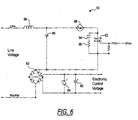
- FIG. 6 illustrates another embodiment of a dropping impedance power supply 80 having a full rectifier bridge 82.
- the dropping impedance power supply 80 is similar to the dropping impedance power supply 50 with the exception of the bridge 82.
- the bridge 82 allows the zener diode 84 to capture the current flow when the line voltage is positive and negative.
- the diode bridge 82 allows current to be supplied to the electronic controls when the line voltage is positive and negative.
- the dropping impedance power supply 80 is a full wave circuit while the dropping impedance power supply 50 is a half wave circuit.
- the current supplied to the electronic controls by the dropping impedance power supply 80 is approximately double that of the dropping impedance power supply 50 of FJG. 5a.
- the dropping impedance power supply 80 of FIG. 6 is similar to the dropping impedance power supply 50, except for the bridge 82.
- the dropping impedance power supply 80 includes the dropping capacitor 86 in parallel with the fan motor 88 for the dropping impedance element.
- the dropping capacitor 86 may be replaced with a resistor.
- the dropping capacitor 86 is the only dropping impedance supplying current to the zener diode 84 to provide power to the electronic controls when the fan 88 is not operating.
- the dropping impedance power supply 80 may provide current, such as approximately 30 mA, to the electronic controls to maintain basic operation of the typical oven operator intcrfacc.
- the fan 88 may be first turned on so that more current is made available to the zener diode reference.
- the dropping power supply 80 transforms the line voltage of approximately 230 volts a.c. to the electronic control voltage of approximately 12 volts d.c.
- the fan motor 88 in parallel with the dropping capacitor 86 drop the voltage from the line
- the diode bridge 82 rectifies the voltage
- the zener diode 84 clamps the voltage across the zener diode 84 at the desired electronic control voltage.
- a filter capacitor 90 filters or smoothes the voltage.
- the bridge 82 rectifies the line voltage to allow the zener diode 84 to clamp the voltage across the zener diode 84 at the desired electronic control voltage To provide the approximately 12 volt d.c.
- the zener diode 84 has a 12 volt rating to clamp the voltage across the zener diode 84 at approximately 12 volts.
- the current flows through both the fan motor 88 and dropping capacitor 86 to provide power to the electronic controls of the oven.
- the dropping impedance power supply 80 of FIG. 6 also includes a triac 92 to control the fan motor 88.
- the electronic controls of the oven provide a drive signal to the triac 92 via pulses.
- a snubber consisting of a series combination of a capacitor 94 and resistor 96 is placed in parallel with the triac 92.
- An inductor 98 together with the dropping capacitor 86 provide the elements of an EMI filter to direct the high frequency disturbances generated by the triac 92 away from the line.
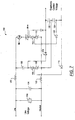
- FIG. 7 illustrates another embodiment of a dropping impedance power supply 100.
- the dropping impedance power supply 100 is similar to the dropping impedance power supply 50 except that the dropping impedance power supply 100 negates the power factor correction behavior of the dropping impedance power supplies 50 and 80.
- One shortcoming of the dropping impedance power supplies 50 and 80 described above is that since current through the dropping capacitor leads the voltage and the current through the fan motor lags the voltage, the instantaneous sum of the two currents will always be lower than the sum of their absolute values.
- the zener reference captures the former, but not the latter.
- the dropping impedance power supply 100 depicted in FIG. 7 on the other hand, through the use of two separate capture circuits, connected to the zener diodes 106/108 and 110/112 respectively, captures both the leading and lagging currents individually, before they sum, thus capturing the maximum available current.
- FIG. 7 illustrates the dropping impedance power supply 100 with separate lagging and leading current capture.
- the dropping impedance power supply 100 has a dropping capacitor 102 with an example capacitance value of approximately one microfarad as a dropping impedance element.
- a fan motor 104 is another the dropping impedance element.
- the dropping capacitance 102 In series with the dropping capacitance 102 are a pair of opposed zener diodes 106 and 108.
- the fan motor 104 is in series with another pair of opposed zener diodes 110 and 112.
- the zener diodes 106, 108, 110 and 112 all have a 12 volt rating.
- Diodes 114, 116, 118 and 120 together with capacitors 122 and 124 rectify the voltage.
- the capacitor 102 may be replaced with a resistor except the resistor would be connected across the fan motor 104 and the triac 128.
- the dropping capacitor 102 provides the current for the electronic controls.
- the zener diode 106 provides a voltage across the capacitor 122 of approximately 12 volts.
- the zener diode 108 provides a voltage across the capacitor 124 of approximately 12 volts.
- the current is flowing through both the dropping capacitor 102 and the fan motor 104.
- the zener diodes 106 and 110 provide a voltage across the capacitor 122 of approximately 12 volts.
- the zener diodes 108 and 112 provide a voltage across the capacitor 124 of approximately 12 volts.
- the dropping impedance power supply 100 of FIG. 7 also includes a triac 128 to control the fan motor 104.
- the electronic controls of the oven provide a drive signal to the triac 128 via pulses.
- the triac 128 generates EMI noise
- inductors 130 and 132 together with a capacitor 134 across the line the dropping capacitor 102 provide the elements of an EMI filter to direct the high frequency disturbances generated by the triac 128 away from the line.
- a surge protector 136 is also placed across the line to protect the power supply 100.
- the inductors 130, capacitor 134 and surge protector 136 have no impact on the power supply function; rather, they provide EMI and surge protection.
Landscapes
- Engineering & Computer Science (AREA)
- Power Engineering (AREA)
- Control Of Ac Motors In General (AREA)
- Control Of Electric Motors In General (AREA)
Priority Applications (1)
| Application Number | Priority Date | Filing Date | Title |
|---|---|---|---|
| EP00200473A EP1124318A1 (de) | 2000-02-11 | 2000-02-11 | Impedanzverluststromversorgung |
Applications Claiming Priority (1)
| Application Number | Priority Date | Filing Date | Title |
|---|---|---|---|
| EP00200473A EP1124318A1 (de) | 2000-02-11 | 2000-02-11 | Impedanzverluststromversorgung |
Publications (1)
| Publication Number | Publication Date |
|---|---|
| EP1124318A1 true EP1124318A1 (de) | 2001-08-16 |
Family
ID=8171007
Family Applications (1)
| Application Number | Title | Priority Date | Filing Date |
|---|---|---|---|
| EP00200473A Withdrawn EP1124318A1 (de) | 2000-02-11 | 2000-02-11 | Impedanzverluststromversorgung |
Country Status (1)
| Country | Link |
|---|---|
| EP (1) | EP1124318A1 (de) |
Cited By (1)
| Publication number | Priority date | Publication date | Assignee | Title |
|---|---|---|---|---|
| ES2264367A1 (es) * | 2005-02-04 | 2006-12-16 | Pablo Garrido Sanchez | Protectores de la ultima farola contra los fallos del neutro. |
Citations (12)
| Publication number | Priority date | Publication date | Assignee | Title |
|---|---|---|---|---|
| CH460921A (de) * | 1967-07-14 | 1968-08-15 | Gegauf Fritz Ag | Elektrische Antriebsvorrichtung |
| FR2248639A1 (en) * | 1973-10-17 | 1975-05-16 | Cellophane Sa | Very low speed DC film drive motor control - uses full wave rectified current and inverted diode in parallel with motor |
| GB1490071A (en) * | 1975-01-02 | 1977-10-26 | Westinghouse Brake & Signal | Electrical power control circuits |
| JPS5566297A (en) * | 1978-11-13 | 1980-05-19 | Matsushita Electric Works Ltd | Power supply circuit for permanent-magnet-field-type dc-motor |
| US4238722A (en) * | 1978-07-20 | 1980-12-09 | Ford Jimmie R | Battery safety jumper cables |
| US4344032A (en) * | 1978-09-22 | 1982-08-10 | Robert Bosch Gmbh | Method and arrangement for testing the characteristics of inductive pulse generators |
| JPS58127589A (ja) * | 1982-01-22 | 1983-07-29 | Takuji Takahashi | 交流電磁機器の微速運転方法 |
| US4417198A (en) * | 1981-08-31 | 1983-11-22 | Duncan Electric Company, Inc. | Average responding RMS indicating type transducer |
| US4638397A (en) * | 1984-12-21 | 1987-01-20 | Xerox Corporation | Self-biased scorotron and control therefor |
| EP0317104A2 (de) * | 1987-11-18 | 1989-05-24 | Norcross Corporation | Steuerschaltung |
| US5714861A (en) * | 1994-05-27 | 1998-02-03 | Eaton Corporation | Variable speed control for a hand-held electric power tool |
| EP0831582A2 (de) * | 1996-09-24 | 1998-03-25 | Veba Kraftwerke Ruhr Aktiengesellschaft | Einrichtung zur Anpassung eines Verbrauchers an die einspeisende Netzspannung |
-
2000
- 2000-02-11 EP EP00200473A patent/EP1124318A1/de not_active Withdrawn
Patent Citations (12)
| Publication number | Priority date | Publication date | Assignee | Title |
|---|---|---|---|---|
| CH460921A (de) * | 1967-07-14 | 1968-08-15 | Gegauf Fritz Ag | Elektrische Antriebsvorrichtung |
| FR2248639A1 (en) * | 1973-10-17 | 1975-05-16 | Cellophane Sa | Very low speed DC film drive motor control - uses full wave rectified current and inverted diode in parallel with motor |
| GB1490071A (en) * | 1975-01-02 | 1977-10-26 | Westinghouse Brake & Signal | Electrical power control circuits |
| US4238722A (en) * | 1978-07-20 | 1980-12-09 | Ford Jimmie R | Battery safety jumper cables |
| US4344032A (en) * | 1978-09-22 | 1982-08-10 | Robert Bosch Gmbh | Method and arrangement for testing the characteristics of inductive pulse generators |
| JPS5566297A (en) * | 1978-11-13 | 1980-05-19 | Matsushita Electric Works Ltd | Power supply circuit for permanent-magnet-field-type dc-motor |
| US4417198A (en) * | 1981-08-31 | 1983-11-22 | Duncan Electric Company, Inc. | Average responding RMS indicating type transducer |
| JPS58127589A (ja) * | 1982-01-22 | 1983-07-29 | Takuji Takahashi | 交流電磁機器の微速運転方法 |
| US4638397A (en) * | 1984-12-21 | 1987-01-20 | Xerox Corporation | Self-biased scorotron and control therefor |
| EP0317104A2 (de) * | 1987-11-18 | 1989-05-24 | Norcross Corporation | Steuerschaltung |
| US5714861A (en) * | 1994-05-27 | 1998-02-03 | Eaton Corporation | Variable speed control for a hand-held electric power tool |
| EP0831582A2 (de) * | 1996-09-24 | 1998-03-25 | Veba Kraftwerke Ruhr Aktiengesellschaft | Einrichtung zur Anpassung eines Verbrauchers an die einspeisende Netzspannung |
Non-Patent Citations (1)
| Title |
|---|
| PATENT ABSTRACTS OF JAPAN vol. 0, no. 0 * |
Cited By (2)
| Publication number | Priority date | Publication date | Assignee | Title |
|---|---|---|---|---|
| ES2264367A1 (es) * | 2005-02-04 | 2006-12-16 | Pablo Garrido Sanchez | Protectores de la ultima farola contra los fallos del neutro. |
| ES2264367B1 (es) * | 2005-02-04 | 2007-11-16 | Pablo Garrido Sanchez | Protectores de la ultima farola contra los fallos del neutro. |
Similar Documents
| Publication | Publication Date | Title |
|---|---|---|
| EP0684685B1 (de) | EMI-Filter und Verfahren zur Bestimmung desselben | |
| US5606232A (en) | DC on line AC brushless motor | |
| US6275400B1 (en) | Dropping impedance power supply | |
| US5532917A (en) | Power factor corrected rectifying circuit | |
| US20060056127A1 (en) | Automated AC line filter and surge suppression apparatus and method | |
| EP0792007A2 (de) | Universeller Leistungsmodul | |
| US7268505B2 (en) | Electric machine and method of operating the electric machine | |
| KR20000050367A (ko) | 공기조화기의 역률개선장치 | |
| CA2951083A1 (en) | Adaptive ac power exchanger | |
| KR20170020199A (ko) | 전도성 노이즈 필터회로, 인버터 장치 및 압축기 | |
| US7327118B2 (en) | Electric machine and method of operating the electric machine | |
| US6853564B2 (en) | Switched linear inductor circuit for switched power supply | |
| CN209283103U (zh) | 电路配置和系统 | |
| US6583998B2 (en) | Power supply regulating having novel charging circuitry | |
| EP1124318A1 (de) | Impedanzverluststromversorgung | |
| CN113271696B (zh) | 电磁感应加热电路及其控制方法、电磁加热设备 | |
| KR100321244B1 (ko) | 공기조화기의 고조파 억제장치 및 그 억제방법 | |
| EP3610544B1 (de) | Kältemaschine und betriebsvorrichtung für einen asynchronen elektromotor | |
| KR20040034905A (ko) | 멀티 에어컨의 인버터 구동장치 | |
| JPH08149822A (ja) | スイッチングレギュレータ | |
| EP3474437A1 (de) | Universale eingangsspannung-kühlmaschine | |
| JP2001045767A (ja) | インバータ装置 | |
| KR20170009559A (ko) | 과전압 보호 회로 | |
| EP1521357A2 (de) | Elektrische Maschine und Verfahren zu deren Betrieb | |
| KR20050061991A (ko) | 과전압 차단 장치 |
Legal Events
| Date | Code | Title | Description |
|---|---|---|---|
| PUAI | Public reference made under article 153(3) epc to a published international application that has entered the european phase |
Free format text: ORIGINAL CODE: 0009012 |
|
| AK | Designated contracting states |
Kind code of ref document: A1 Designated state(s): AT BE CH CY DE DK ES FI FR GB GR IE IT LI LU MC NL PT SE |
|
| AX | Request for extension of the european patent |
Free format text: AL;LT;LV;MK;RO;SI |
|
| 17P | Request for examination filed |
Effective date: 20011004 |
|
| AKX | Designation fees paid |
Free format text: AT BE CH CY DE DK ES FI FR GB GR IE IT LI LU MC NL PT SE |
|
| STAA | Information on the status of an ep patent application or granted ep patent |
Free format text: STATUS: THE APPLICATION IS DEEMED TO BE WITHDRAWN |
|
| 18D | Application deemed to be withdrawn |
Effective date: 20070901 |