EP1124288A1 - Balais à fil gainé en métal noble et dispositif de bague collectrice - Google Patents
Balais à fil gainé en métal noble et dispositif de bague collectrice Download PDFInfo
- Publication number
- EP1124288A1 EP1124288A1 EP01102994A EP01102994A EP1124288A1 EP 1124288 A1 EP1124288 A1 EP 1124288A1 EP 01102994 A EP01102994 A EP 01102994A EP 01102994 A EP01102994 A EP 01102994A EP 1124288 A1 EP1124288 A1 EP 1124288A1
- Authority
- EP
- European Patent Office
- Prior art keywords
- slip ring
- brush
- core
- wire
- noble metal
- Prior art date
- Legal status (The legal status is an assumption and is not a legal conclusion. Google has not performed a legal analysis and makes no representation as to the accuracy of the status listed.)
- Withdrawn
Links
Images


Classifications
-
- H—ELECTRICITY
- H01—ELECTRIC ELEMENTS
- H01R—ELECTRICALLY-CONDUCTIVE CONNECTIONS; STRUCTURAL ASSOCIATIONS OF A PLURALITY OF MUTUALLY-INSULATED ELECTRICAL CONNECTING ELEMENTS; COUPLING DEVICES; CURRENT COLLECTORS
- H01R39/00—Rotary current collectors, distributors or interrupters
- H01R39/02—Details for dynamo electric machines
- H01R39/18—Contacts for co-operation with commutator or slip-ring, e.g. contact brush
- H01R39/20—Contacts for co-operation with commutator or slip-ring, e.g. contact brush characterised by the material thereof
-
- H—ELECTRICITY
- H01—ELECTRIC ELEMENTS
- H01R—ELECTRICALLY-CONDUCTIVE CONNECTIONS; STRUCTURAL ASSOCIATIONS OF A PLURALITY OF MUTUALLY-INSULATED ELECTRICAL CONNECTING ELEMENTS; COUPLING DEVICES; CURRENT COLLECTORS
- H01R13/00—Details of coupling devices of the kinds covered by groups H01R12/70 or H01R24/00 - H01R33/00
- H01R13/02—Contact members
- H01R13/03—Contact members characterised by the material, e.g. plating, or coating materials
-
- H—ELECTRICITY
- H01—ELECTRIC ELEMENTS
- H01R—ELECTRICALLY-CONDUCTIVE CONNECTIONS; STRUCTURAL ASSOCIATIONS OF A PLURALITY OF MUTUALLY-INSULATED ELECTRICAL CONNECTING ELEMENTS; COUPLING DEVICES; CURRENT COLLECTORS
- H01R39/00—Rotary current collectors, distributors or interrupters
- H01R39/02—Details for dynamo electric machines
- H01R39/18—Contacts for co-operation with commutator or slip-ring, e.g. contact brush
- H01R39/24—Laminated contacts; Wire contacts, e.g. metallic brush, carbon fibres
Definitions
- the present invention relates generally to slip ring and wire brush assemblies and, more particularly, to the use of noble metal materials forming a surface layer of a wire brush.
- Slip ring assemblies are well known in the prior art and generally comprise a rotating conductive ring in contact with a non-rotating brush mounted in a suitable brush holder.
- the brush is often a monolithic wire element comprising a gold alloy brush wire or a gold plated wire running against a gold plated ring.
- Gold or other noble metals are highly preferred since it has been known for some time that to achieve performance over long periods of time (years) with contact resistance variations in the low milliohm levels, noble metals and noble metal alloys must be used in the electrical contact zone rather than base metals.
- Gold alloy brush wires can be expected to operate for long periods of time with minimal contact resistance variations.
- gold alloy wires are relatively expensive since the gold content is high.
- Gold plated wires are also known and tend to be less expensive than gold alloy wires since the gold plating covers a less expensive base metal.
- the gold plating is susceptible to cracking, especially when the gold plated brush wire is bent to a particular radius of curvature for certain types of applications.
- the manufacture of plated wires require a more substantial capital investment in view of the need for plating baths and equipment, and also create environmental disposal problems and additional related expense.
- Another object is to improve wear characteristics of noble metal covered brush wires.
- Yet another object is to improve the structural integrity and wear characteristics of noble metal covered brush wires relative to platted wires while lowering costs relative to noble metal alloy wires.
- This present invention relates to a slip ring and brush assembly including a slip ring in sliding contact with a brush wire.
- the invention relates to an improvement wherein the brush wire includes a first material forming at least part of a wire core and a second material forming an outer layer metallurgically bonded to the first material.
- the invention relates to a slip ring and brush assembly for transmitting electrical energy between a conductor and a shaft.
- One of the conductor and shaft is stationary while the other is rotating.
- the assembly comprises a noble metal covered slip ring surface formed on the shaft and at least one brush wire in contact with the noble metal covered slip ring surface and coupled to the conductor.
- the brush wire includes a conductive core, an optional metal barrier layer covering the core, and a noble metal surface layer metallurgically bonded to one of the barrier layer and core.
- the feature of metallurgically bonding the noble metal surface layer to the underlying core, either directly or through an intermediate metallurgically bonded barrier layer, advantageously results in better brush forming by providing intimate attachment conditions at the atomic level that minimizes cracking or peeling of the precious metal surface relative to prior art plating techniques.
- Brush wires formed with the metallurgically bonded noble metal surface also tend to be less expensive than gold or noble metal alloy wire by reducing the gold or noble metal content while retaining the same precious metal contact at the ring/brush interface for low noise and wear.
- the brush wire according to the present invention utilizes an optional metal barrier layer to prevent diffusion between the conductor core and noble surface layer depending on the selection of materials between which diffusion may be a problem.
- the barrier layer is preferably metallurgically bonded to the conductor core and the noble metal surface layer is in turn metallurgically bonded to the barrier layer.
- the brush wire comprises a copper center core, preferably Beryllium copper, with a nickel clad overlay barrier followed by a gold cladding on the outer surface of the nickel barrier.
- FIG 1. is an exemplary illustration of a slip ring and brush assembly, generally designated with reference numeral 10, in which a series of brush wires 12 are in sliding contact with a slip ring surface 14 formed on a rotating slip ring assembly 15.
- the respective surfaces of the brush wires 12 and slip ring surface 14 are preferably gold covered to achieve good wear characteristics, low electrical resistance and increase current density as is well known.
- each brush wire 12 includes a surface layer 16 in the form of a gold cladding layer 16a that is metallurgically bonded in the preferred embodiment to an underlying conductive core 16b, either directly or through a diffusion layer 16c (see FIG. 2) that in turn is metallurgically bonded to the core.
- the advantages of gold-on-gold low contact resistance are achieved while avoiding either the higher likelihood of fatigue and failure problems associated with gold plating, or the increased costs of gold alloy wire with their higher gold content.
- Assembly 10 is representative of a large class of brush wire and slip ring assemblies in which the rotating conductive slip ring assembly 15 is contacted by a non-rotating brush 12 mounted in a suitable brush holder to provide flow paths for electrical power or signal.
- assembly 10 comprises a cylindrical housing 20 in which a pair of bearings 22 and 24 are disposed at opposite ends of slip ring assembly 15 to rotatably support one end of a rotating shaft 28.
- a series of brush wires 12 are disposed in axially spaced location in respective contact with annular grooves 30 formed along the length of the slip ring assembly 15.
- upper and lower sets of axially sets 12a and 12b of axially spaced identical brush wires 12 are mounted to respective upper and lower brush blocks 32 and 34 that provide for proper wire positioning in sliding or rotating contact with the slip ring assembly grooves 30.
- each brush block assembly 32 and 34 extends the length of the slip ring assembly 15 and has opposite ends in respective contact with bearings 22 and 24 to properly position the bearings within the assembly 10.
- the brush blocks 32 and 34 are also used for positioning and locating the lead wires 36, and provide lead exits as known in the art.
- the lead wires 36 are retained in position in relation to the brush block assemblies 32, 34 by utilizing a potting material 38 disposed between the outer surface of each brush block and the inner surface wall of the housing 20.
- a retainer ring 40 disposed in a recessed proximal end of the housing 20 is used to axially fix the brush block assemblies 32, 34 relative to the rotating shaft 28 while an end cap 42 closes off the distal end of the assembly 10 through which the lead wires 36 extend.
- each brush wire 12 in the preferred embodiment includes a surface layer 16 in the form of a cladding layer 16a that is metallurgically bonded to an underlying conductive core 16b preferably through a diffusion layer 16c.
- the cladding layer 16a is preferably made of a noble material, such as gold.
- the feature of metallurgically bonding the outer layer 16a either to the underlying core 16b or diffusion layer 16c provides much better attachment conditions than previously achieved with gold or noble metal plating due to the tendency of plated materials to wear faster as a result of the inferior attachment conditions between the plated layer and substrate inherent in plating technology. This inherent disadvantage of plating is particularly noticeable and disadvantageous in products relying upon one or more brush wires in sliding or rotating contact with an associated slip ring assembly.
- Brush wires 12 constructed in accordance with the unique features of the present invention tend to offer similar performance (i.e. in terms of wear rates and longevity) provided by high gold content and therefore higher priced gold alloy brush wires but without the concomitant costs.
- the noble metal clad brush wire 12 of the invention also offers the ability to provide better conductivity than gold alloy wire of similar dimension by being bonded to a center core material 16b selected to have better conductivity then a pure gold alloy.
- the ability to bond the cladding layer 16a to a center core 16b of a different material enables the resulting brush wire 12 to have superior mechanical properties in relation to gold alloy wires depending on the selection of the center core material.
- the feature of using noble metal clad wires also offer better formability as compared to plated wires as a result of superior bonding attachment provided by metallurgical bonding relative to plating. This improved formability is evidenced by fewer incidences of cracking or peeling of the surface layer 16a which is particularly useful when the brush wire is bent on a tight radius.
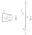
- the noble metal clad wires of the invention have particularly advantageous benefits when used in brush wires having, for example, a horse shoe shape of the type depicted in Fig. 3 as is used in the assembly 10 of the preferred embodiment.
- the invention is not limited to the use of gold but is intended to cover other noble metals.
- the invention is also applicable to brush wires used with sliding or rotating contacts in which a surface material forming an outer layer is metallurgically bonded to a core material, with or without an intermediate cladding layer, so that the benefits of metallurgical bonding as described above may be realized that would otherwise not be realized by attachment of such surface material with plating techniques.
- the invention is applicable to the use of both monofilament and multifilament materials forming the individual brush wires and brush wire assemblies.
- each wire 12 is formed with a gold outer layer 16a that is metallurgically bonded to the diffusion layer 16c (e.g. Nickel) in turn metallurgically bonded to the core 16b (e.g. Beryllium copper).
- the diffusion layer 16c e.g. Nickel
- the core 16b e.g. Beryllium copper
- a diffusion layer 16c is unnecessary in which case the outer layer is metallurgically bonded to the core.
- Figure 4 is a detailed side view of a multifilament brush assembly 100 that may comprise a plurality of filaments 102 which made be in the 1 to 25 mil size and which are held in a unitary relationship by means of a collar 104.
- the collar 104 may comprise the end portion of a wire insulation, or maybe a separate tube element specifically designed to hold the fibers 102 in a selectively shaped bundle.
- the fibers 102 extend from the collar 104 a sufficient distance to enable them to be in tangential contact with the slip ring surface, as well know (see e.g. U.S. Patent No. 4,398,113).
- each fiber 102 is constructed in a manner similar to that described above in connection with brush wire 12. That is, each fiber 102 is preferably in the form of a cladding layer that is metallurgically bonded to an underlying conductive core preferably through a diffusion layer.
- the cladding layer is preferably made of a noble material, such as gold.
- the feature of metallurgically bonding the outer layer either to the underlying core or to a diffusion layer provides much better attachment conditions than previously achieved with gold or noble metal plating as described above.
Landscapes
- Motor Or Generator Current Collectors (AREA)
Applications Claiming Priority (2)
| Application Number | Priority Date | Filing Date | Title |
|---|---|---|---|
| US499535 | 1995-07-07 | ||
| US49953500A | 2000-02-11 | 2000-02-11 |
Publications (1)
| Publication Number | Publication Date |
|---|---|
| EP1124288A1 true EP1124288A1 (fr) | 2001-08-16 |
Family
ID=23985637
Family Applications (1)
| Application Number | Title | Priority Date | Filing Date |
|---|---|---|---|
| EP01102994A Withdrawn EP1124288A1 (fr) | 2000-02-11 | 2001-02-08 | Balais à fil gainé en métal noble et dispositif de bague collectrice |
Country Status (3)
| Country | Link |
|---|---|
| EP (1) | EP1124288A1 (fr) |
| JP (1) | JP2002017073A (fr) |
| CA (1) | CA2334502A1 (fr) |
Cited By (3)
| Publication number | Priority date | Publication date | Assignee | Title |
|---|---|---|---|---|
| EP2816676A1 (fr) * | 2013-06-21 | 2014-12-24 | Tektronix, Inc. | Connecteur robuste haute fréquence |
| US9601444B2 (en) | 2014-02-27 | 2017-03-21 | Tektronix, Inc. | Cable mounted modularized signal conditioning apparatus system |
| US9882331B2 (en) | 2012-08-06 | 2018-01-30 | Schleifring And Apparatebau Gmbh | Low cost gold wire brushes |
Families Citing this family (2)
| Publication number | Priority date | Publication date | Assignee | Title |
|---|---|---|---|---|
| CN113193459B (zh) * | 2021-05-14 | 2022-07-29 | 中国航发湖南动力机械研究所 | 一种刷丝座集成工艺 |
| CN116255352B (zh) * | 2023-05-11 | 2023-07-14 | 中国空气动力研究与发展中心低速空气动力研究所 | 一种防冰风扇组件以及防冰风扇系统 |
Citations (3)
| Publication number | Priority date | Publication date | Assignee | Title |
|---|---|---|---|---|
| US4398113A (en) * | 1980-12-15 | 1983-08-09 | Litton Systems, Inc. | Fiber brush slip ring assembly |
| EP0318831A2 (fr) * | 1987-12-02 | 1989-06-07 | Inco Limited | Connecteurs électriques de puissance |
| JPH0746797A (ja) * | 1993-07-29 | 1995-02-14 | Mitsumi Electric Co Ltd | 直流モータ |
-
2001
- 2001-02-05 JP JP2001067728A patent/JP2002017073A/ja not_active Withdrawn
- 2001-02-07 CA CA 2334502 patent/CA2334502A1/fr not_active Abandoned
- 2001-02-08 EP EP01102994A patent/EP1124288A1/fr not_active Withdrawn
Patent Citations (3)
| Publication number | Priority date | Publication date | Assignee | Title |
|---|---|---|---|---|
| US4398113A (en) * | 1980-12-15 | 1983-08-09 | Litton Systems, Inc. | Fiber brush slip ring assembly |
| EP0318831A2 (fr) * | 1987-12-02 | 1989-06-07 | Inco Limited | Connecteurs électriques de puissance |
| JPH0746797A (ja) * | 1993-07-29 | 1995-02-14 | Mitsumi Electric Co Ltd | 直流モータ |
Non-Patent Citations (1)
| Title |
|---|
| PATENT ABSTRACTS OF JAPAN vol. 1995, no. 05 30 June 1995 (1995-06-30) * |
Cited By (7)
| Publication number | Priority date | Publication date | Assignee | Title |
|---|---|---|---|---|
| US9882331B2 (en) | 2012-08-06 | 2018-01-30 | Schleifring And Apparatebau Gmbh | Low cost gold wire brushes |
| EP2696450B1 (fr) * | 2012-08-06 | 2020-09-30 | Schleifring GmbH | Balais à faible coût avec un fil couvert d'or |
| EP2816676A1 (fr) * | 2013-06-21 | 2014-12-24 | Tektronix, Inc. | Connecteur robuste haute fréquence |
| CN104241987A (zh) * | 2013-06-21 | 2014-12-24 | 特克特朗尼克公司 | 强健的高频连接器 |
| US9099791B2 (en) | 2013-06-21 | 2015-08-04 | Tektronix, Inc. | Cable assembly having a coaxial cable with outer conductor not protruding a housing surrounding the cable |
| CN104241987B (zh) * | 2013-06-21 | 2019-05-10 | 特克特朗尼克公司 | 强健的高频连接器 |
| US9601444B2 (en) | 2014-02-27 | 2017-03-21 | Tektronix, Inc. | Cable mounted modularized signal conditioning apparatus system |
Also Published As
| Publication number | Publication date |
|---|---|
| JP2002017073A (ja) | 2002-01-18 |
| CA2334502A1 (fr) | 2001-08-11 |
Similar Documents
| Publication | Publication Date | Title |
|---|---|---|
| US7041943B2 (en) | Electrical heating element for heating units of seats and steering wheels | |
| EP0891254B1 (fr) | Balais en fibres metalliques a contact permanent | |
| JPH0234155B2 (fr) | ||
| EP0310668B1 (fr) | Borne de connexion electrique revetue de ceramique | |
| MY115718A (en) | Sliding contact material, clad composite material, commutator employing said material and direct current motor employing said commutator | |
| US20070120437A1 (en) | Compact slip ring incorporating fiber-on-tips contact technology | |
| EP2696450B1 (fr) | Balais à faible coût avec un fil couvert d'or | |
| FR2815707B1 (fr) | Detecteur de contact glissant | |
| US20040121622A1 (en) | Slip ring with connector pins | |
| EP1124288A1 (fr) | Balais à fil gainé en métal noble et dispositif de bague collectrice | |
| US20110234040A1 (en) | Commutator | |
| KR102133616B1 (ko) | 슬립 링을 위한 링 전극, 대응하는 슬립 링, 및 링 전극을 제조하기 위한 방법 | |
| US20090058219A1 (en) | Slip ring for continuous current transfer | |
| CA2264902A1 (fr) | Electrode d'erosion de forte intensite | |
| JP4372657B2 (ja) | スリップリング装置 | |
| CN103608976B (zh) | 用于滑动触点的电线和滑动触点 | |
| CN208127597U (zh) | 纤维刷束滑环总成 | |
| US4430635A (en) | Variable resistance device | |
| EP1339141A1 (fr) | Dispositif symétrique à ressort pour balai en charbon pour moteur à courant continu | |
| JPH04341598A (ja) | 電気めっき用陽極構体 | |
| US6644977B1 (en) | Assembly for transmitting electrical signals and/or energy | |
| JPH06158353A (ja) | 電池ばね用鋼線 | |
| US4385977A (en) | Apparatus for electroplating a metal wire of relatively low electric conductivity | |
| US5691863A (en) | Power feeding device for VTR rotating drum | |
| JPH0244106B2 (ja) | Denkyosetsuten |
Legal Events
| Date | Code | Title | Description |
|---|---|---|---|
| PUAI | Public reference made under article 153(3) epc to a published international application that has entered the european phase |
Free format text: ORIGINAL CODE: 0009012 |
|
| AK | Designated contracting states |
Kind code of ref document: A1 Designated state(s): DE FR GB |
|
| AX | Request for extension of the european patent |
Free format text: AL;LT;LV;MK;RO;SI |
|
| 17P | Request for examination filed |
Effective date: 20020208 |
|
| AKX | Designation fees paid |
Free format text: DE FR GB |
|
| STAA | Information on the status of an ep patent application or granted ep patent |
Free format text: STATUS: THE APPLICATION HAS BEEN WITHDRAWN |
|
| 18W | Application withdrawn |
Effective date: 20030127 |