EP1124167B1 - Dispositif permettant l'orientation d'une couronne à vis d'une montre. - Google Patents
Dispositif permettant l'orientation d'une couronne à vis d'une montre. Download PDFInfo
- Publication number
- EP1124167B1 EP1124167B1 EP20010810100 EP01810100A EP1124167B1 EP 1124167 B1 EP1124167 B1 EP 1124167B1 EP 20010810100 EP20010810100 EP 20010810100 EP 01810100 A EP01810100 A EP 01810100A EP 1124167 B1 EP1124167 B1 EP 1124167B1
- Authority
- EP
- European Patent Office
- Prior art keywords
- watch
- crown
- ring
- tube
- screwed
- Prior art date
- Legal status (The legal status is an assumption and is not a legal conclusion. Google has not performed a legal analysis and makes no representation as to the accuracy of the status listed.)
- Expired - Lifetime
Links
- 229910001285 shape-memory alloy Inorganic materials 0.000 claims description 2
- 229910045601 alloy Inorganic materials 0.000 description 3
- 239000000956 alloy Substances 0.000 description 3
- 230000008878 coupling Effects 0.000 description 3
- 238000010168 coupling process Methods 0.000 description 3
- 238000005859 coupling reaction Methods 0.000 description 3
- 238000010079 rubber tapping Methods 0.000 description 2
- 238000004804 winding Methods 0.000 description 2
- 230000008602 contraction Effects 0.000 description 1
- 230000003247 decreasing effect Effects 0.000 description 1
- 230000001419 dependent effect Effects 0.000 description 1
- 230000006870 function Effects 0.000 description 1
- 238000004519 manufacturing process Methods 0.000 description 1
- 230000003446 memory effect Effects 0.000 description 1
- 229910001092 metal group alloy Inorganic materials 0.000 description 1
- 229910001000 nickel titanium Inorganic materials 0.000 description 1
- 238000007789 sealing Methods 0.000 description 1
Images

Classifications
-
- G—PHYSICS
- G04—HOROLOGY
- G04B—MECHANICALLY-DRIVEN CLOCKS OR WATCHES; MECHANICAL PARTS OF CLOCKS OR WATCHES IN GENERAL; TIME PIECES USING THE POSITION OF THE SUN, MOON OR STARS
- G04B3/00—Normal winding of clockworks by hand or mechanically; Winding up several mainsprings or driving weights simultaneously
- G04B3/04—Rigidly-mounted keys, knobs or crowns
- G04B3/041—Construction of crowns for rotating movement; connection with the winding stem; winding stems
-
- G—PHYSICS
- G04—HOROLOGY
- G04B—MECHANICALLY-DRIVEN CLOCKS OR WATCHES; MECHANICAL PARTS OF CLOCKS OR WATCHES IN GENERAL; TIME PIECES USING THE POSITION OF THE SUN, MOON OR STARS
- G04B37/00—Cases
- G04B37/08—Hermetic sealing of openings, joints, passages or slits
- G04B37/10—Hermetic sealing of openings, joints, passages or slits of winding stems
- G04B37/103—Hermetic sealing of openings, joints, passages or slits of winding stems by screwing the crown onto the case
Definitions
- the present invention relates to a device for adjusting the orientation of a crown to a watch with respect to the watch, said ring being able to take a unscrewed position and a screwed position relative to the middle part of a tube fixed to the middle part .
- the present invention also relates to a watch comprising such a device.
- screw crowns on watches are well known.
- the crown can take a unscrewed position in which it is possible to set the time of the watch, the date etc. and a screwed position, which is the position in which the watch is worn, in which the crown is tightened and locked on the tube of the watch.
- a problem with conventional crowns is that it is very difficult, if not impossible, to orient permanently during production, the corresponding threads of the middle part of the watch and the crown of that, for each watch produced, the screwed crown, is always in the same position relative to the middle part. This can be problematic if the shape of the crown is not symmetrical in particular, or if the crown has a particular logo: the position of the crown or the logo relative to the caseband is then different for each watch produced, once that the crown is screwed.
- the document CH 242,198 discloses a sealed crown winding screwing on the box and having, inside an axial tube, a coupling device with the winding stem, arranged and shaped so that said crown can perform, when unscrewed , reassembly and time setting functions.
- the axial tube is fixedly attached to the ring gear and has, at its opposite end to the ring gear, a part projecting inside and constituting one of the elements of the coupling, the other elements of the coupling being introduced. in the tube before fixing it to the crown.
- the object of the invention is to improve the known devices.
- the object of the invention is to propose a simple system which makes it possible to fine-adjust the position of the screwed crown relative to the middle part, while preserving the sealing qualities of the watch.
- the claim 6 defines a watch comprising a device according to the invention.
- the figure 1 shows a sectional view of a first embodiment of the invention.
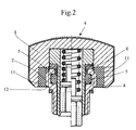
- the figure 2 shows a sectional view of a second embodiment of the invention.
- the first embodiment of the invention is shown by way of example.
- a ring 1 which is screwed onto a tube 2, said tube being itself fixed to the middle part 3 of the watch.
- This crown may further comprise a logo 4, schematized by dashed lines.
- several seals are placed between the ring and the tube to seal, namely an O-ring 5 and a first flat seal 6 which is compressed when the crown 1 is screwed onto the tube 2.
- the crown 1 is screwed onto the tube 2 by means of a suitable thread 7 in the ring 1 and a corresponding thread 8 on the tube 2.
- the means for adjusting the position of the ring 1 relative to the middle part 3 of the watch comprise a ring 10 which is placed between the middle part 3 and the tube 2.
- this ring 10 is formed in a shape memory metal alloy, for example a nickel-titanium alloy such as the "Micro-Niti" alloy from the company Microfil Industries SA. Thanks to this intermediate ring, a system is obtained which enables An angular adjustment of the crown 1. In fact, by appropriately using the shape memory effect related to the temperature, it is possible to realize a system allowing a fine adjustment which is independent of the start of the thread 8 of the tube 2. and the beginning of tapping 7 of the ring 1.
- the ring 10 completely closes the connection it makes between the middle part 3 and the tube 2, at room temperature and despite normal temperature differences that could be experienced by a watch being worn.
- the rotation of the tube 2 is blocked and the position of the ring 1 screwed relative to the middle part 3 is fixed.
- the figure 2 shows a second embodiment of the invention, in which, the elements identical to the first embodiment have the same references, the main difference residing in the position of the ring 10 of the figure 1 .
- the ring bears the reference 11 and is not between the tube 2 and the middle part 3 (see figure 1 ) but between the ring 1 itself and the tube 2.
- the tube 2 is driven conventionally in the middle part of the watch (not shown), and it is the ring 11 itself that supports the tapping 12 of the ring 1 which is intended to be screwed on the thread of the tube 2.
- shape memory alloy ring is a non-limiting example. Other alloys are possible. Similarly, other equivalent systems allowing in particular to temporarily create a game between the crown and the middle part of the watch are possible, the idea being to allow such a game that in particular conditions and to prevent it under conditions normal use.
Landscapes
- Physics & Mathematics (AREA)
- General Physics & Mathematics (AREA)
- Electric Clocks (AREA)
Description
- La présente invention concerne un dispositif pour régler l'orientation d'une couronne à vis d'une montre par rapport à la montre, ladite couronne pouvant prendre une position dévissée et une position vissée par rapport à la carrure sur un tube fixé à la carrure. La présente invention concerne également une montre comportant un tel dispositif.
- L'utilisation de couronnes à vis sur des montres est bien connue. En général, la couronne peut prendre une position dévissée dans laquelle il est possible de régler l'heure de la montre, la date etc. et une position vissée, qui est la position dans laquelle on porte la montre, dans laquelle la couronne est serrée et bloquée sur le tube de la montre.
- Un problème auquel l'on est confronté avec les couronnes classiques est qu'il est très difficile, voire impossible, d'orienter de manière permanente au cours de la production, les filetages correspondants de la carrure de la montre et de la couronne de façon à ce que, pour chaque montre produite, la couronne vissée, soit toujours dans la même position relativement à la carrure. Cela peut poser des problème si la forme de la couronne n'est pas symétrique notamment, ou si la couronne comporte un logo particulier: la position de la couronne ou du logo par rapport à la carrure est alors différente pour chaque montre produite, une fois que la couronne est vissée.
- Le document
CH 242 198 - Le but de l'invention est d'améliorer les dispositifs connus.
- Plus particulièrement, l'invention a pour but de proposer un système simple qui permette d'ajuster de manière fine la position de la couronne vissée par rapport à la carrure, tout en conservant les qualités d'étanchéité de la montre.
- Ce but est atteint par les caractéristiques de la revendication 1.
- Les revendications dépendantes 2 à 5 définissent des modes d'exécution particuliers du système selon l'invention.
- La revendication 6 définit une montre comportant un dispositif selon l'invention.
- L'invention sera mieux comprise par la description de deux modes d'exécution de celle-ci et des figures qui les accompagnent.
- La
figure 1 montre une vue en coupe d'un premier mode d'exécution de l'invention. - La
figure 2 montre une vue en coupe d'un deuxième mode d'exécution de l'invention. - Dans la
figure 1 , on a représenté, à titre d'exemple, le premier mode d'exécution de l'invention. Dans ce mode, on trouve une couronne 1 qui est vissée sur un tube 2, ledit tube étant lui-même fixé à la carrure 3 de la montre. Cette couronne peut en outre comporter un logo 4, schématisé par des traits tiretés. De manière classique, plusieurs joints sont placés entre la couronne et le tube pour assurer l'étanchéité, à savoir un joint O-ring 5 et un premier joint plat 6 qui est comprimé lors du vissage de la couronne 1 sur le tube 2. - Le vissage de la couronne 1 sur le tube 2 s'effectue par l'intermédiaire d'un taraudage 7 approprié dans la couronne 1 et d'un filetage 8 correspondant sur le tube 2.
- On trouve encore un deuxième joint plat 9 entre le tube 2 et la carrure 3 qui permet d'assurer l'étanchéité du boîtier de montre. Ce deuxième joint plat est facultatif lorsque le tube 2 est soudé ou chassé sur la carrure 3.
- Les moyens permettant l'ajustement de la position de la couronne 1 par rapport à la carrure 3 de la montre comprennent une bague 10 qui est placée entre la carrure 3 et le tube 2. Pour le mode d'exécution de la
figure 1 , cette bague 10 est formée dans un alliage métallique à mémoire de forme, par exemple un alliage de nickel-titane comme l'alliage "Micro-Niti" de la société Microfil Industries S.A. Grâce à cette bague intermédiaire, on obtient un système qui permet un ajustement angulaire de la couronne 1. En effet, en utilisant de manière appropriée l'effet de mémoire de forme lié à la température, il est possible de réaliser un système permettant un ajustement fin qui est indépendant du début du filetage 8 du tube 2 et du début du taraudage 7 de la couronne 1. Dans le cas présent, il est nécessaire que la bague 10 ferme de manière complètement étanche la liaison qu'elle réalise entre la carrure 3 et le tube 2, à la température ambiante et malgré des écarts de température normaux que pourrait subir une montre qui est portée. Ainsi, la rotation du tube 2 est bloquée et la position de la couronne 1 vissée par rapport à la carrure 3 est fixe. - En revanche, en utilisant des températures particulières, qui dépendent de l'alliage utilisé pour la bague 10, on peut arriver à diminuer la taille de la bague 10 et ainsi permettre une rotation du tube 2 par rapport à la carrure 3. Lors du montage d'une montre, il est alors très facile de régler la position d'une couronne 1 serrée sur le tube 2 en créant un jeu temporaire entre le tube 2 et la carrure 3 par contraction de la bague 10. Ainsi, on obtient des séries de montres qui, après ajustement, comportent des couronnes vissées orientées toutes dans la même direction par rapport à la carrure.
- La
figure 2 montre une deuxième forme d'exécution de l'invention, dans laquelle, les éléments identiques au premier mode d'exécution ont les mêmes références, la principale différence résidant dans la position de la bague 10 de lafigure 1 . Dans ce cas en effet, la bague porte la référence 11 et se trouve non pas entre le tube 2 et la carrure 3 (voirfigure 1 ) mais entre la couronne 1 elle-même et le tube 2. En fait, le tube 2 est chassé de manière classique dans la carrure de la montre (non-représentée), et c'est la bague 11 elle-même qui supporte le taraudage 12 de la couronne 1 qui est destiné à se visser sur le filetage du tube 2. De même que dans le premier mode d'exécution de lafigure 1 , en jouant sur la déformation de la bague 11, en particulier en diminuant son diamètre, on peut créer un jeu temporaire entre la couronne 1 et le tube 2, ce qui permet d'ajuster angulairement la position vissée de la couronne sur le tube 2. Celui-ci étant fixe par rapport à la carrure, on ajuste par conséquent la position angulaire de la couronne 1 par rapport au boîtier de la montre elle-même. - Bien entendu, l'utilisation de bague en alliage à mémoire de forme est un exemple non-limitatif. D'autres alliages sont possibles. De même, d'autres systèmes équivalents permettant en particulier de créer temporairement un jeu entre la couronne et la carrure de la montre sont possibles, l'idée étant de permettre un tel jeu que dans des conditions particulières et de l'empêcher dans des conditions d'utilisation normales.
Claims (5)
- Dispositif pour régler l'orientation d'une couronne (1) à vis d'une montre par rapport à la montre, ladite couronne (1) pouvant prendre une position dévissée et une position vissée par rapport à la carrure (3) sur un tube (2) fixé à la carrure (3), ledit dispositif comprenant des moyens ajustables, caractérisé en ce que lesdits moyens ajustables comprennent une bague (10, 11) agencée pour être placée soit entre la couronne (1) et le tube (2) soit entre le tube (2) et la carrure (3),la constitution de ladite bague (10, 11) permettant, par contraction ou déformation de ladite bague, de créer temporairement un jeu entre la couronne (1) et la carrure (3), permettant d'orienter angulairement la couronne (1) vissée par rapport à la carrure (3) de manière que la couronne vissée ait une orientation déterminée par rapport à la carrure, et d'empêcher le dit jeu dans des conditions d'utilisation normale de la montre.
- Dispositif selon la revendication 1, caractérisé en ce que ladite bague (10;11) est en un alliage à mémoire de forme.
- Montre comprenant un dispositif selon la revendication 2, caractérisé en ce que ladite bague (10) est placée entre la carrure (3) et le tube (2) supportant la couronne (1).
- Montre comprenant un dispositif selon la revendication 2 , caractérisé en ce que ladite bague (11) est placée entre la couronne (1) et le tube (2) supportant la couronne (1).
- Montre caractérisée en ce qu'elle comprend un dispositif selon l'une des revendications précédentes.
Applications Claiming Priority (2)
| Application Number | Priority Date | Filing Date | Title |
|---|---|---|---|
| CH00247/00A CH705649B1 (fr) | 2000-02-08 | 2000-02-08 | Dispositif permettant le réglage de l'orientation d'une couronne à vis d'une montre par rapport à la carrure de la montre. |
| CH2472000 | 2000-02-08 |
Publications (2)
| Publication Number | Publication Date |
|---|---|
| EP1124167A1 EP1124167A1 (fr) | 2001-08-16 |
| EP1124167B1 true EP1124167B1 (fr) | 2010-04-07 |
Family
ID=4466066
Family Applications (1)
| Application Number | Title | Priority Date | Filing Date |
|---|---|---|---|
| EP20010810100 Expired - Lifetime EP1124167B1 (fr) | 2000-02-08 | 2001-02-01 | Dispositif permettant l'orientation d'une couronne à vis d'une montre. |
Country Status (3)
| Country | Link |
|---|---|
| EP (1) | EP1124167B1 (fr) |
| CH (1) | CH705649B1 (fr) |
| DE (1) | DE60141726D1 (fr) |
Cited By (1)
| Publication number | Priority date | Publication date | Assignee | Title |
|---|---|---|---|---|
| EP3974915A4 (fr) * | 2019-05-20 | 2023-02-22 | Citizen Watch Co., Ltd. | Piece d'horlogerie |
Families Citing this family (17)
| Publication number | Priority date | Publication date | Assignee | Title |
|---|---|---|---|---|
| EP1411401A1 (fr) * | 2002-10-17 | 2004-04-21 | Ks 22 Sa | Couronne à vis pour pièce d'horlogerie |
| JP4728000B2 (ja) | 2005-01-17 | 2011-07-20 | セイコーインスツル株式会社 | 携帯時計 |
| EP1701225B1 (fr) | 2005-03-09 | 2012-02-22 | Boninchi S.A. | Couronne vissée pour pièce d'horlogerie |
| EP1727005B1 (fr) * | 2005-05-24 | 2008-04-23 | Pibor ISO S.A. | Couronne à visser et procédé d'assemblage d'une telle couronne sur une boîte de montre |
| JP4652942B2 (ja) * | 2005-10-05 | 2011-03-16 | セイコーインスツル株式会社 | 携帯時計 |
| CH699877A1 (fr) * | 2008-10-31 | 2010-05-14 | Pibor Iso S A | Couronne a visser et procédé d'orientation d'une telle couronne sur une boîte de montre. |
| EP2385432A2 (fr) * | 2010-05-04 | 2011-11-09 | Rolex Sa | Boîte de montre |
| CH705090A2 (fr) | 2011-06-08 | 2012-12-14 | Omega Sa | Dispositif pour l'orientation d'une couronne vissée d'une pièce d'horlogerie. |
| EP2915012B1 (fr) | 2012-11-02 | 2021-03-31 | Omega SA | Dispositif pour l'orientation d'un élément vissé d'une pièce d'horlogerie |
| EP2746870B1 (fr) * | 2012-12-18 | 2017-02-08 | Meco S.A. | Couronne démontable |
| CH708743A2 (fr) | 2013-10-25 | 2015-04-30 | Meco Sa | Joint pour pièce d'horlogerie. |
| EP3279745B1 (fr) | 2016-08-02 | 2023-06-14 | Meco S.A. | Couronne vissee orientable |
| EP3432085B1 (fr) * | 2017-07-20 | 2020-04-15 | Meco S.A. | Soupape de sécurité pour pièce d'horlogerie |
| EP3495896A1 (fr) | 2017-12-11 | 2019-06-12 | Barigna SA | Montre munie d'un organe de commande du mécanisme intérieur |
| EP3805872B1 (fr) * | 2019-10-09 | 2025-11-26 | Meco S.A. | Couronne vissee orientable |
| EP3805873B1 (fr) * | 2019-10-09 | 2023-12-06 | Meco S.A. | Couronne vissee orientable |
| EP4006647B1 (fr) * | 2020-11-25 | 2023-05-10 | Meco S.A. | Couronne-poussoir pour pièce d'horlogerie |
Family Cites Families (1)
| Publication number | Priority date | Publication date | Assignee | Title |
|---|---|---|---|---|
| CH242198A (fr) * | 1944-06-28 | 1946-04-30 | Rolex Montres | Remontoir étanche. |
-
2000
- 2000-02-08 CH CH00247/00A patent/CH705649B1/fr not_active IP Right Cessation
-
2001
- 2001-02-01 EP EP20010810100 patent/EP1124167B1/fr not_active Expired - Lifetime
- 2001-02-01 DE DE60141726T patent/DE60141726D1/de not_active Expired - Lifetime
Cited By (3)
| Publication number | Priority date | Publication date | Assignee | Title |
|---|---|---|---|---|
| EP3974915A4 (fr) * | 2019-05-20 | 2023-02-22 | Citizen Watch Co., Ltd. | Piece d'horlogerie |
| US11921464B2 (en) | 2019-05-20 | 2024-03-05 | Citizen Watch Co., Ltd. | Timepiece |
| JP7476185B2 (ja) | 2019-05-20 | 2024-04-30 | シチズン時計株式会社 | 時計 |
Also Published As
| Publication number | Publication date |
|---|---|
| DE60141726D1 (de) | 2010-05-20 |
| EP1124167A1 (fr) | 2001-08-16 |
| CH705649B1 (fr) | 2013-04-30 |
Similar Documents
| Publication | Publication Date | Title |
|---|---|---|
| CH705649B1 (fr) | Dispositif permettant le réglage de l'orientation d'une couronne à vis d'une montre par rapport à la carrure de la montre. | |
| EP1927037B1 (fr) | Dispositif de fixation d'un fond sur une carrure d'une montre | |
| EP1048988A2 (fr) | Dispositif de verrouillage de la couronne de remontoir d'une montre | |
| EP2290477A1 (fr) | Ensemble de fixation de l'extrémite péripherique du spiral d'un dispositif à balancier-spiral pour pièce d'horlogerie | |
| EP2182417A2 (fr) | Couronne à visser et procédé d'orientation d'une telle couronne sur une boîte de montre | |
| EP1701225B1 (fr) | Couronne vissée pour pièce d'horlogerie | |
| WO2001040881A1 (fr) | Procede de montage d'une couronne vissee sur une boîte de montre et boîte de montre munie d'une telle couronne | |
| EP3805873B1 (fr) | Couronne vissee orientable | |
| EP1890203A1 (fr) | Boîte de montre comprenant un fond et procédé de fixation d'un fond sur une boîte de montre | |
| EP3805874B1 (fr) | Couronne vissee orientable | |
| EP2228693A1 (fr) | Dispositif de fixation pour timbres d'une montre a sonnerie | |
| WO1997039386A1 (fr) | Montre | |
| EP3805870B1 (fr) | Boîte de montre avec couronne vissée orientable | |
| EP3805869B1 (fr) | Couronne vissée | |
| EP0770937B1 (fr) | Pièce d'horlogerie comportant une lunette tournante | |
| CH717211A2 (fr) | Couronne pour boîte de pièce d'horlogerie, tige pour mouvement horloger et pièce d'horlogerie. | |
| EP3805872B1 (fr) | Couronne vissee orientable | |
| EP3495896A1 (fr) | Montre munie d'un organe de commande du mécanisme intérieur | |
| CH719969A1 (fr) | Dispositif de fixation pour des composants horlogers ou joaillers | |
| EP3321749B1 (fr) | Joint d'étanchéité pour l'horlogerie | |
| CH689955A5 (fr) | Pièce d'horlogerie comportant une lunette tournante. | |
| EP3985450A1 (fr) | Dispositif de blocage d'un mouvement d'une pièce d'horlogerie | |
| FR2497972A1 (fr) | Dispositif miniature d'etancheite entre un organe de commande exterieur et une boite en metal precieux de montre extra-plate | |
| FR2747028A1 (fr) | Dispositif de fixation d'une tige d'osteosynthese rachidienne orientable a moyens de confirmation de blocage angulaire | |
| CH646570A5 (en) | Watch case |
Legal Events
| Date | Code | Title | Description |
|---|---|---|---|
| PUAI | Public reference made under article 153(3) epc to a published international application that has entered the european phase |
Free format text: ORIGINAL CODE: 0009012 |
|
| AK | Designated contracting states |
Kind code of ref document: A1 Designated state(s): CH DE FR IT LI |
|
| AX | Request for extension of the european patent |
Free format text: AL;LT;LV;MK;RO;SI |
|
| 17P | Request for examination filed |
Effective date: 20011219 |
|
| AKX | Designation fees paid |
Free format text: CH DE FR IT LI |
|
| 17Q | First examination report despatched |
Effective date: 20060731 |
|
| TPAC | Observations by third parties |
Free format text: ORIGINAL CODE: EPIDOSNTIPA |
|
| GRAP | Despatch of communication of intention to grant a patent |
Free format text: ORIGINAL CODE: EPIDOSNIGR1 |
|
| GRAS | Grant fee paid |
Free format text: ORIGINAL CODE: EPIDOSNIGR3 |
|
| GRAA | (expected) grant |
Free format text: ORIGINAL CODE: 0009210 |
|
| AK | Designated contracting states |
Kind code of ref document: B1 Designated state(s): CH DE FR IT LI |
|
| REG | Reference to a national code |
Ref country code: CH Ref legal event code: EP |
|
| REF | Corresponds to: |
Ref document number: 60141726 Country of ref document: DE Date of ref document: 20100520 Kind code of ref document: P |
|
| REG | Reference to a national code |
Ref country code: CH Ref legal event code: NV Representative=s name: BUGNION S.A. |
|
| PLBE | No opposition filed within time limit |
Free format text: ORIGINAL CODE: 0009261 |
|
| STAA | Information on the status of an ep patent application or granted ep patent |
Free format text: STATUS: NO OPPOSITION FILED WITHIN TIME LIMIT |
|
| 26N | No opposition filed |
Effective date: 20110110 |
|
| REG | Reference to a national code |
Ref country code: FR Ref legal event code: PLFP Year of fee payment: 16 |
|
| REG | Reference to a national code |
Ref country code: FR Ref legal event code: PLFP Year of fee payment: 17 |
|
| REG | Reference to a national code |
Ref country code: FR Ref legal event code: PLFP Year of fee payment: 18 |
|
| PGFP | Annual fee paid to national office [announced via postgrant information from national office to epo] |
Ref country code: DE Payment date: 20190211 Year of fee payment: 19 Ref country code: IT Payment date: 20190208 Year of fee payment: 19 Ref country code: FR Payment date: 20190125 Year of fee payment: 19 Ref country code: CH Payment date: 20190125 Year of fee payment: 19 |
|
| REG | Reference to a national code |
Ref country code: DE Ref legal event code: R119 Ref document number: 60141726 Country of ref document: DE |
|
| REG | Reference to a national code |
Ref country code: CH Ref legal event code: PL |
|
| PG25 | Lapsed in a contracting state [announced via postgrant information from national office to epo] |
Ref country code: LI Free format text: LAPSE BECAUSE OF NON-PAYMENT OF DUE FEES Effective date: 20200229 Ref country code: CH Free format text: LAPSE BECAUSE OF NON-PAYMENT OF DUE FEES Effective date: 20200229 |
|
| PG25 | Lapsed in a contracting state [announced via postgrant information from national office to epo] |
Ref country code: FR Free format text: LAPSE BECAUSE OF NON-PAYMENT OF DUE FEES Effective date: 20200229 Ref country code: DE Free format text: LAPSE BECAUSE OF NON-PAYMENT OF DUE FEES Effective date: 20200901 |
|
| PG25 | Lapsed in a contracting state [announced via postgrant information from national office to epo] |
Ref country code: IT Free format text: LAPSE BECAUSE OF NON-PAYMENT OF DUE FEES Effective date: 20200201 |