EP1124124A2 - Testing device for viscosified fluid - Google Patents
Testing device for viscosified fluid Download PDFInfo
- Publication number
- EP1124124A2 EP1124124A2 EP01301109A EP01301109A EP1124124A2 EP 1124124 A2 EP1124124 A2 EP 1124124A2 EP 01301109 A EP01301109 A EP 01301109A EP 01301109 A EP01301109 A EP 01301109A EP 1124124 A2 EP1124124 A2 EP 1124124A2
- Authority
- EP
- European Patent Office
- Prior art keywords
- fluid
- projections
- cup
- viscometer
- support
- Prior art date
- Legal status (The legal status is an assumption and is not a legal conclusion. Google has not performed a legal analysis and makes no representation as to the accuracy of the status listed.)
- Withdrawn
Links
Images


Classifications
-
- G—PHYSICS
- G01—MEASURING; TESTING
- G01N—INVESTIGATING OR ANALYSING MATERIALS BY DETERMINING THEIR CHEMICAL OR PHYSICAL PROPERTIES
- G01N11/00—Investigating flow properties of materials, e.g. viscosity, plasticity; Analysing materials by determining flow properties
- G01N11/10—Investigating flow properties of materials, e.g. viscosity, plasticity; Analysing materials by determining flow properties by moving a body within the material
- G01N11/14—Investigating flow properties of materials, e.g. viscosity, plasticity; Analysing materials by determining flow properties by moving a body within the material by using rotary bodies, e.g. vane
Definitions
- This invention relates generally to devices and methods that are used to test viscosified fluids, especially such fluids which contain particulate material (subsequently referred to simply as "particulate").
- particulate subsequently referred to simply as "particulate”.
- the particular field of use is the oil and gas industry.
- Non-limiting examples include drilling muds, cement slurries, and stimulation treating fluids.
- Such fluids are typically pumped into oil or gas wells in known manners. It is desirable to know various characteristics of the fluids to determine how such fluids will act upon being pumped and placed in, or circulated through, the wells.
- Viscosity, elasticity, and consistency are rheological characteristics that sometimes need to be measured for a given fluid.
- Known devices used to test fluids for these characteristics include viscometers, rheometers, and consistometers.
- fracturing fluid might include a base fluid in a gel form and a quantity of particulate referred to as a propping agent or proppant.
- a propping agent or proppant is sand.
- the base fluid preferably supports the proppant such that the proppant is suspended in the fluid during the time the mixture is pumped into a well.
- the pumping is under pressure sufficient for the fluid to hydraulically fracture a selected zone of the earth traversed by the well.
- the fluid may be flushed out with the flow of hydrocarbons from the fractured zone, but the propping agent preferably remains in place to prop the fractures open.
- Viscosity is defined as the ratio of shear stress to shear rate (velocity gradient). If this ratio changes with shear rate, this may be referred to as "apparent viscosity function". Viscosity is one parameter of the fluid that defines the fluid's ability to support the particulate in suspension. However, to measure a single viscosity point or the apparent viscosity function does not directly indicate the time during which the fluid will support particulate in suspension and the time during which the fluid will not. That is, a measurement that merely shows a changing viscosity does not indicate when the particulate is in suspension within the fluid and when it is not (i.e.
- a device and method which can test fluids to determine times during which particulate is suspended in the fluid and times during which particulate settles out of suspension.
- a device and method to measure the viscous and elastic properties of a fluid, both with and without particulate, under dynamic conditions at elevated temperatures and pressures at a variety of shear rates and in such a way as to directly indicate particle transport, suspension and settling.
- At least one embodiment of such a device and method preferably should also be suitable for use at a well site to measure crosslink time of a fluid being pumped into the well.
- Such device and method can directly indicate time periods during which a tested fluid is supporting particulate in suspension and when the tested fluid is not (i.e. when the particulate is settling out of suspension).
- the invention provides a mixer viscometer comprising a receptacle having a cavity to receive a viscous and/or elastic fluid containing particulate; means for closing the cavity such that the closed cavity defines a continuous test chamber which can be pressurized above atmospheric pressure; means for stirring fluid in the test chamber; and means for generating a signal in response to said stirring.
- the invention provides a particle transport capability detector apparatus comprising a viscometer including a viscometer cup and further including an axial shaft disposed within the cup when the fluid to be tested is in the cup; at least two projections extending laterally outward from the axial shaft of the viscometer; and at least one projection extending laterally inward from an inner surface of the viscometer cup, wherein the projections effect stirring of fluid in the cup in response to relative rotation of the cup and the axial shaft, and wherein each of the projections preferably has a triangular shape.
- the invention further includes a viscometer test chamber, comprising a slurry cup; a pressure-sealed end closure for the slurry cup; a support hanging below the end closure into the slurry cup when the end closure is connected to the slurry cup to close the slurry cup; not more than four vertical planar projections extending laterally outward from the support; and not more than four vertical planar projections extending laterally inward from an inner surface of the slurry cup, wherein the projections effect stirring of fluid in the slurry cup in response to relative rotation between the slurry cup and the support; and wherein each of the projections preferably has a triangular shape.
- a device of the present invention may be referred to as a high-pressure, high-temperature mixer viscometer that can measure viscous and elastic properties and crosslink and particulate transport time.
- This implementation includes a paddle type of mixing device which has one or more flags, paddles, or vanes which rotate in or around the fluid to be tested and two or more flags, paddles or vanes in a torque sensing structure.
- the device is capable of measuring varying volume average shear rates and volume average shear stresses, signifying varying viscosities, and is especially useful at low shear rates.
- This device can condition the fluid under test at low, ambient, and elevated temperatures and pressures.
- This device provides an output that can be used to measure or indicate viscous and elastic properties of the test fluid (which can be with or without particulate material), the change in fluid properties with time (e.g. crosslink time), particle transport (particle suspension and particle settling), and particle-to-particle interactions and degree of adhesive coating on particles (e.g. higher torque readings for more particle-to-particle interaction, such as from higher particle concentrations, or for increased adhesive coating).
- the test fluid which can be with or without particulate material
- the change in fluid properties with time e.g. crosslink time
- particle transport particle suspension and particle settling
- particle-to-particle interactions and degree of adhesive coating on particles e.g. higher torque readings for more particle-to-particle interaction, such as from higher particle concentrations, or for increased adhesive coating.
- the present invention also provides a method of testing for particulate transport time of a fluid containing particulate.
- the method comprises stirring, for a time during which the viscosity or elasticity of the fluid changes, a fluid containing particulate such that during a first period of the stirring time substantially all the particulate remains suspended in the fluid and during a second period of the stirring time substantially all the particulate settles out of suspension in the fluid.
- the method further comprises generating a signal during the first and second periods such that the signal has a characteristic that changes from the first period to the second period to indicate the change in particulate carrying ability of the fluid.
- the method of the present invention can also be defined as comprising: using in a high-pressure, high-temperature viscometer a container having at least one inward projection and using in the viscometer an axial support having at least two outward projections, wherein the container holds a viscous and/or elastic fluid containing particulate and the support extends into the fluid; creating relative movement between the container and the support, and the projections thereof; and generating a measurement signal in response to a characteristic of the viscometer occurring by creating the relative movement such that the measurement signal indicates an elastic particulate transport time period and a viscous settling time period.
- generating a measurement signal includes generating an electric signal in response to torque related to creating relative movement between the container and the support and the projections thereof.
- the measurement signal also may indicate, prior to the elastic particulate transport time period and the viscous settling time period, a crosslinking time during which the fluid becomes viscoelastic.
- Still another definition of the method of testing a viscosified fluid containing particulate comprises: mixing sand and a basegel to form a sand-gel slurry mixture; putting at least a portion of the mixture in a slurry cup having at least two inward projections extending inward from an inside surface of the cup; connecting the slurry cup in a viscometer having an axial support from which at least two outward projections extend outward; increasing pressure in the connected slurry cup such that pressure on the mixture in the cup is greater than atmospheric pressure; creating relative movement between the slurry cup and the axial support, and the projections thereof, such that the projections impart a stirring force in the fluid under pressure; and generating a measurement signal in response to a characteristic of the viscometer occurring by creating the relative movement.
- the method may further comprise heating the mixture in the slurry cup to a temperature greater than ambient temperature (and preferably greater than 212°F).
- Still a further definition of the present invention is as a method of testing a fluid containing particulate, comprising: using a viscometer a cup having at least one inward projection and using in the viscometer an axial support having at least two outward projections, wherein the cup receives fluid containing particulate and the support extends into the fluid; creating relative movement between the cup and the support, and the projections thereof; and generating a measurement signal in response to a characteristic of the viscometer occurring by creating the relative movement such that the measurement signal indicates a crosslinking time for the fluid.
- the method of the present invention may further comprise placing in the container at a well site a sample of the fluid taken from a stream of the fluid as the stream is flowing into the well, and performing the using, creating and generating steps at the well site as the stream is flowing into the well.
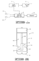
- FIG. 1 is a block diagram of a viscometer having a modified test cell implementing a preferred embodiment of the present invention, which viscometer is illustrated in an environment at an oil or gas well site and which viscometer can be an open-cup type or a high-pressure and/or high-temperature type.
- FIG. 2 is a schematic illustration of the modified test cell of a particular implementation of the preferred embodiment.
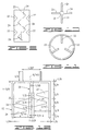
- FIG. 3 is a representation of another configuration of projections in the present invention.
- FIG. 4 is a representation of a further configuration of projections in the present invention.
- FIG. 5 is a representation of still another configuration of projections in the present invention.
- FIG. 6 is a representation of a still further configuration of projections in the present invention.
- FIG. 7 is a representation of yet another configuration of projections in the present invention.
- FIG. 8 is a representation of a further configuration of projections in the present invention.
- FIG. 9 is a representation of another configuration of projections in the present invention.
- FIG. 10 is a plan view representation of four projections spaced around an axial support.
- FIG. 11 is a plan view representation of three projections spaced around an inner surface of a cup for holding a fluid to be tested.
- FIG. 12 represents yet another configuration of projections in the present invention, with dimensions for a particular implementation.
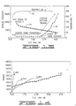
- FIG. 13 is a graphical representation of a traditional viscosity measurement and temperature measurement, as well as of a particle transport capability measurement in accordance with the method of the present invention, for a particular example of a viscosified fluid.
- FIG. 14 is a graphical representation of measurements for modified fluids to illustrate a type of comparative analysis that can be made with the particle transport capability measurement depicted in FIG. 13.
- FIG. 15 is a graph showing a response to crosslinking in the test fluid and such fluid becoming viscoelastic.
- a type of fluid with which the present invention can be used is referred to as a viscous and/or elastic fluid whose viscosity changes over time.
- One such fluid is a viscoelastic fluid that may typically go through different phases over time; for example, from an initial uncrosslinked state, to a crosslinked elastic state, to a viscous settling state.
- the particulate to be used in the fluid can be, for example, sized sand, resin coated sand, sintered bauxite beads, metal beads or balls, ceramic particles, glass beads, polymer resin beads, ground nut shells and the like.
- the particulate size may be of any suitable size, with typical sizes being within the range from about 8 to about 170 on the U.S. Sieve Series scale.
- a more general statement about a mixture for which the present invention is particularly intended is that it is a mixture of a particulate and a fluid which during one period of time is able to support the quantity of particulate in suspension under a stirring action but which during another period of time is unable to support the particulate in suspension even under the stirring action.
- the invention also measures viscous and/or elastic properties of the fluid itself without sand. Examples include drilling muds, cement slurries, and stimulation treating fluids used in the oil and gas industry.
- One preferred embodiment device of the present invention that tests a fluid such as described above is implemented with a high-pressure (above ambient), high-temperature (above 212°F) viscometer which includes a receptacle to receive the fluid to be tested and which also includes a support that is disposed in the receptacle (and thus also in the fluid) when the fluid is in the receptacle to be tested.
- a viscometer can be a conventional one (e.g., a Fann model 50 viscometer) but adapted to the present invention by a modified test cell 2.
- the present invention can also be used with, or incorporate, a conventional open-cup or atmospheric viscometer (e.g., a Fann model 35 viscometer), but also adapted by a modified test cell 2.
- this modified test cell 2 includes at least one projection extending laterally inward from an inner surface of the receptacle mentioned above and forming part of the modified test cell.
- the modified test cell 2 also preferably includes at least two projections extending laterally outward from the support mentioned above.
- Such device of the present invention is depicted in FIG. 1 and can otherwise comprise conventional components of a high-pressure, high-temperature viscometer, including pressure control 4, temperature control 6, and readout 8, or of an atmospheric type viscometer that does not have at least the pressure control 4.
- either embodiment can be used at a well site to receive in real time a sample of the mixture from a fluid stream 7 flowing into an oil or gas well 9.
- a receptacle 10 includes a conventional slurry cup of a conventional viscometer of the high-pressure, high-temperature type referred to above.
- the receptacle 10 has a cylindrical side wall 12 extending from an end closed by a bottom wall 14 to an open end opposite the bottom wall 14.
- the side wall 12 and the bottom wall 14 have inner surfaces defining a cavity 16 in the receptacle 10.
- the cavity 16 receives the fluid to be tested. This cavity provides a single continuous volume or cell for the fluid to be tested.
- the modified test cell 2 of the FIG. 2 embodiment also includes means for closing the open end of the cavity 16 or receptacle 10 after the fluid is placed in the cavity 16.
- This closing means completes the definition of the outer boundaries of the continuous test chamber which can be pressurized above atmospheric pressure.
- the closing means includes a conventional pressure sealed end closure 18 for the slurry cup defining the receptacle 10.
- the closing means also includes the aforementioned support, which in the FIG. 2 implementation is an axial shaft 20. This axial shaft hangs below the end closure 18 into the slurry cup when the end closure is connected to the slurry cup in conventional manner to close the slurry cup.
- pressure sealed end closure 18 and the axial shaft 20 is found in the aforementioned Fann model 50 viscometer; however, other high-pressure, high-temperature devices can be used (and as mentioned, the present invention has application with devices that need not have high-pressure or high-temperature capability, such as an open-cup viscometer).
- the modified test cell shown in FIG. 2 further includes means for stirring fluid in the test chamber such that particulate in the fluid is suspended in the fluid during one period of time of the stirring but is not suspended in the fluid during another period of time of the stirring.
- This is implemented in FIG. 2 by at least one projection extending into the cavity from the inner surface of the receptacle 10.
- two flat, substantially triangular metallic projections 22 are connected to the inner surface of the receptacle 10 diametrically opposite each other. Connection can be by any suitable means, including but not limited to welding to or integrally machining with the cup wall. In other embodiments, a single projection 22 can be used or more than two projections 22 can be used.
- the FIG. 2 implementation also includes at least two projections extending laterally outward from the axial support 20, preferably in a rotationally balanced configuration and positioned to have desired sensitivity to settling particulate.
- Two diametrically opposed, axially spaced projections 24 of the same type as projections 22 are connected to the axial shaft 20 in the FIG. 2 embodiment. While there may be two or more projections 24, preferably there is an even number of these projections. Connection can be by any suitable means, including but not limited to welding to or integrally machining with the support 20 or a mandrel that connects to the support 20.
- the projections 22, 24 are large enough to generate a torque during stirring, but small enough to produce a torque reading within a desired range (the larger the projections, the larger the torque reading) and to leave a gap between the set of projections 22 and the set of projections 24 sufficient for the particulate material to pass through without bridging (e.g., three to four particle diameters).
- the projections 24 operatively cooperate with the projections 22 to effect stirring of fluid in the slurry cup in response to rotation of at least one of the slurry cup or support.
- the slurry cup is rotated so that the projections 22 principally effect the stirring, and the projections 24 are deflected in response to thereby sense torque.
- This rotation is achieved in conventional manner within the remainder of the viscometer used to implement the described embodiment of the present invention.
- the rotation to be imparted is such that mixing of the particulate in suspension within the fluid occurs during a period of the stirring time in which the fluid is still able to support the particulate, but the rotation is not such that mixing occurs when the fluid is no longer able to support the particulate in suspension, whereby the particulate settles out of suspension.
- the rotation is also obtained in a manner that permits an appropriate readout signal to be generated. Such rotation is typically within the range between one revolution per minute and one thousand revolutions per minute.
- the embodiment of the present invention shown in FIGS. 1 and 2 includes a readout 8. This is part of a means for generating a signal in response to the stirring of the fluid during both the period during which particulate suspension occurs and the period during which particulate settling occurs.
- This is implemented in FIG. 2 by using the two or more projections 24 on the axial shaft. For example, when the slurry cup is rotated, torque is sensed through the axial shaft in known manner. In an embodiment in which the axial shaft is rotated to effect mixing by the projections 24, torque is sensed through the slurry cup or the axial shaft in known manner.
- the sensitivity of the readout to such torque can be adjusted by using different strengths of springs or different sizes of flags (projections) or different transducers.
- a lighter weight spring is used in the present invention as compared to the spring used in the conventional viscometer construction and operation.
- An electric signal is generated in known manner in response to the deflection of the axial shaft 20; and the electric signal is used in known manner to create a display, such as an electronic display or a printed graph. As explained further hereinbelow, the display is maintained so that a graph of the response over time is obtained in accordance with the present invention.
- FIGS. 4, 5 and 7 show respective projections 24 extending from the respective support 20 which are axially spaced along the support, and respective projections 22 extending from the slurry cup which are axially aligned (i.e., on the same circumference of the inner surface of the slurry cup wall).
- FIG. 3 shows respective projections 24 extending from the respective support 20 which are axially spaced along the support, and respective projections 22 extending from the slurry cup which are axially spaced.
- FIG. 8 shows projections 24 extending from the support 20 which are axially aligned along the support, and projections 22 extending from the slurry cup which are axially spaced.
- FIG. 9 shows axially spaced projections 24 with slurry cup projections 22 in axially spaced groups, in which groups the projections 22 are axially aligned.
- FIG. 6 shows two axially spaced projections 24 from the axial shaft and a single projection 22 from the slurry cup wall.
- FIG. 10 illustrates four projections 24 equally spaced around the axial shaft 20, and
- FIG. 11 illustrates three equally spaced projections 22 from the slurry cup.
- the projections of FIGS. 3, 4, 5 and 9 are triangular, those in FIG. 6 are rectangular, the ones in FIG.
- FIG. 7 are elliptical, and the projections in FIG. 8 are semicircular.
- FIG. 12 illustrates a specific implementation of triangular projections 22, 24 on an open slurry cup 10 and an axial shaft 20, respectively (the cup 10 is the rotated member in this embodiment, such as in a Fann model 35 viscometer modified with the projections of the present invention, and in use is immersed in the fluid held by an outer container of a type used in the art).
- the projections 22, 24 of the preferred embodiments are flat, planar members that are disposed vertically (i.e., the major planar surfaces of such member are vertical) as depicted in the drawings.
- the projections 22, 24 also are sized such that not more than four would typically be used along the vertical or axial direction on either the axial shaft 20 or the viscometer cup 10. Indeed, in the particular embodiment of FIG. 12, there is only a single vertical group on the shaft 20 and two vertically spaced projections or groups on the viscometer cup 10 (in FIG.
- each projection has a base 5/8-inch wide, a length of 1 inch and a width or thickness of 1/8 inch; the projections are disposed within a space of 1 7/8 inches of the overall cup body height of 2 7/8 inches). See also FIGS. 2-11.
- the projections 22, 24 are made of any material suitable for the substances, pressures, temperatures, and rotational characteristics to be encountered in using the present invention, as known in the art.
- the preferred embodiment device described above with reference to FIGS. 1 and 2, or any suitable configuration of projections is one device that can be used to perform the high-pressure, high-temperature embodiment of the present method; however, it is not contemplated to be the exclusive way of performing it (e.g., an open-cup configuration as shown in FIG. 12 can be used if high-pressure, high-temperature testing is not required).
- the device of the present invention is not limited to the preferred embodiments described above.
- the present invention provides a method of testing a viscosified fluid containing particulate, which method comprises using in a high-pressure, high-temperature viscometer a container having at least one inward projection. It also preferably includes using in the viscometer an axial support having at least two outward projections. The container holds the fluid, and the support extends into the fluid. The method further comprises creating relative movement between the container and the support, and the projections thereof. At least one set of these projections imparts a stirring force in the fluid. Relative movement is preferably created by rotating in known manner either the slurry cup of the viscometer or the axial support of the viscometer.
- the method still further includes generating a measurement signal in response to a characteristic of the viscometer occurring by creating the relative movement.
- the measurement signal is an electric signal generated in response to torque related to creating relative movement between the container and the support and the projections thereof.
- Such electric signal can be generated with conventional torque sensing components of the viscometer which respond to deflection of the axial shaft by the force of the fluid against the projections on the axial shaft.
- the axial deflection may be read directly on a dial without the use of an electrical signal or signal generating means.
- the relative movement is created for a time during which the viscosity and/or elasticity of the fluid changes, which time includes a first period during which substantially all the particulate remains suspended in the fluid and which time includes a second period during which substantially all the particulate settles out of suspension in the fluid (such as due to the viscosity and/or elasticity of the fluid decreasing to a level which does not support the particulate). That is, rotation (e.g., by a motor connected and operated in known manner) continues throughout the range of viscosity change from the aforementioned first period through the aforementioned second period.
- the measurement signal taken over time has a characteristic which indicates the first period (an elastic particulate transport time period) and the second time period (a viscous settling time period).
- the measurement signal can also indicate, prior to the aforementioned first period, crosslinking that occurs in the fluid; in particular, it indicates a crosslinking time during which the fluid becomes viscoelastic.
- stirring preferably includes either (1) rotating the slurry cup relative to a support disposed in the fluid, wherein the cup has at least one projection extending inward into the fluid from the cup and the support has at least two projections extending outward into the fluid from the support, or (2) rotating the support disposed in the fluid relative to the slurry cup.
- the former is typically preferred because of the lighter mass of the axial shaft structure relative to the cup structure.
- a more specific definition of the present invention includes: mixing sand and a basegel (i.e., a liquid viscosified with a non-crosslinked polymer in solution) to form a sand-gel slurry mixture; putting at least a portion of the mixture in a slurry cup having at least two inward projections extending inward from an inside surface of the cup; connecting the slurry cup in a viscometer having an axial support from which at least two outward projections extend outward; increasing pressure in the connected slurry cup such that pressure on the mixture in the cup is greater than atmospheric pressure; creating relative movement between the slurry cup and the axial support, and the projections thereof, such that the projections impart a stirring force on the fluid under pressure; and generating a measurement signal in response to a characteristic of the viscometer occurring by creating the relative movement.
- a basegel i.e., a liquid viscosified with a non-crosslinked polymer in solution
- This definition of the method can also comprise heating the mixture in the slurry cup to a temperature greater than ambient temperature. This heating is applied in the preferred embodiment in a conventional manner for high-pressure, high-temperature viscometers.
- the following example exemplifies this more specific definition of the method of the present invention, but it is also encompassed by the other definitions described above.
- the temperature graph is marked with the reference number 30 and the torque measurement obtained in accordance with the present invention is marked with the reference number 32.
- a corresponding cross-linked gel test fluid without sand was tested at 250°F in a standard Fann Model 50 viscometer; the corresponding torque graph is marked with the reference number 34 in FIG. 13.
- the temperature increases up to the test temperature in about 30 minutes.
- the line 34 shows a decrease with time in the viscosity of the cross-linked gel fluid with breaker. This curve is typical for viscosity decline and it shows no indication of whether or not the gel will support sand.
- the curve 32 shows the torque reading versus time from the present invention.
- the cross-linked gel slurry supports sand and has minimal resistance to flow for a period of time (about 2.5 hours). This is the period of elastic transport, or perfect particulate transport, where any settling is offset by the motion of the rotating slurry cup and the interacting projections 22, 24. There is a slight decrease in resistance due to the decrease in viscosity of the supporting gel.
- the viscous settling region described above and illustrated in FIG. 13 can be calibrated or compared by measuring the slopes of non-crosslinked linear gel fluids containing a similar concentration of the sand or other particulate.
- guar polymers at concentrations of 0.48 to 1.2% were hydrated in water, sand was added to the fluid, and the slurries were measured using the present invention. All of the curves have a positive slope, indicating that sand settling occurs from the beginning of the test. There is no time where perfect proppant transport occurs.
- These curves may be compared to the slopes of the crosslinked gel fluids as an indication of the type of transport and effective gel concentration in the viscous settling region.
- the present invention also may be used to determine crosslink time for the fluid. This occurs prior to the two time periods referred to above and typically occurs within a matter of minutes rather than several minutes or hours as in the time periods illustrated in FIG. 13.
- a graph showing a measurement by the mixer viscometer of the present invention responding to the fluid crosslinking and becoming viscoelastic is shown in FIG. 15.
- another definition of the method of the present invention is as a method of testing a fluid containing particulate, comprising: using in a viscometer a container having at least one inward projection and using in the viscometer an axial support having at least two outward projections, wherein the container holds the fluid which contains particulate and the support extends into the fluid; creating relative movement between the container and the support, and the projections thereof; and generating a measurement signal in response to a characteristic of the viscometer occurring by creating the relative movement such that the measurement signal indicates a crosslinking time for the fluid.
- the method also may include that the measurement signal be taken over time subsequent to the crosslinking time to indicate a particulate transport time period and a particulate settling time period as described above.
- generating a measurement signal includes generating an electric signal in response to torque related to creating relative movement between the container and the support and the projections thereof.
- the method may further comprise placing in the container at a well site a sample of the fluid taken from a stream of the fluid as the stream is flowing into the well, and performing the using, creating and generating steps at the well site as the stream is flowing into the well.
- the open cup embodiment (such as partially illustrated in FIG. 12) is particularly suitable because a sample of fluid can be readily extracted from the stream in known manner, poured into a beaker or other suitable container known in the art, and the beaker or container operatively placed in known manner relative to the open slurry cup 10 of the FIG. 12 embodiment.
- This method enables real-time crosslink time testing at the well site, the results of which can then be used to modify the fluid pumped into the well.
- viscous and elastic properties can be determined by using the torque signal with known mathematical concepts (see, for example, United States Patent No. 5,799,734; J.F. Steffe, Rheological Methods in Food Process Engineering (second edition), Freeman Press, East Lansing, Michigan; and K.L. Mackey, R.G. Morgan and J.F. Steffe, "Effects of Shear-Thinning Behavior on Mixer Viscometry Techniques," Michigan Agricultural Experiment Station Journal Article No. 12280, April 1, 1987; the foregoing incorporated herein by reference).
Landscapes
- Physics & Mathematics (AREA)
- Health & Medical Sciences (AREA)
- Life Sciences & Earth Sciences (AREA)
- Chemical & Material Sciences (AREA)
- Analytical Chemistry (AREA)
- Biochemistry (AREA)
- General Health & Medical Sciences (AREA)
- General Physics & Mathematics (AREA)
- Immunology (AREA)
- Pathology (AREA)
- Sampling And Sample Adjustment (AREA)
Abstract
Description
Claims (25)
- A mixer viscometer comprising a receptacle (10) having a cavity (16) to receive a viscous and/or elastic fluid containing particulate; means (18) for closing the cavity such that the closed cavity defines a continuous test chamber which can be pressurized above atmospheric pressure; means (22 or 24) for stirring fluid in the test chamber; and means for generating a signal in response to said stirring.
- A mixer viscometer according to claim 1, wherein the means for stirring includes at least one projection (22) extending into the cavity from an inner surface of the receptacle (10) defining the cavity (16).
- A mixer viscometer according to claim 1 or 2, wherein the means for generating a signal includes an axial support (20) extending into the cavity in the receptacle, and at least two projections (24) extending outward from the axial support.
- A mixer viscometer according to claim 3, wherein the means for stirring includes at least two projections (22) extending into the cavity from an inner surface of the receptacle (10) defining the cavity (16).
- A mixer viscometer according to claim 3 or 4, wherein the means for generating includes an even number of the projections extending outward from the axial support.
- A particle transport capability detector apparatus comprising a viscometer including a viscometer cup and further including an axial shaft disposed within the cup when the fluid to be tested is in the cup; at least two projections extending laterally outward from the axial shaft of the viscometer; and at least one projection extending laterally inward from an inner surface of the viscometer cup, wherein the projections effect stirring of fluid in the cup in response to relative rotation of the cup and the axial shaft, and wherein each of the projections preferably has a triangular shape.
- Apparatus according to claim 6, wherein an even number of projections extend laterally outward from the axial shaft of the viscometer, and two or more projections extend laterally inward from the inner surface of the viscometer cup.
- Apparatus according to claim 6 or 7, wherein at least two of the projections extending from the axial shaft are axially spaced or axially aligned along the shaft, and wherein there are at least two axially aligned or at least two axially spaced projections extending from the viscometer cup.
- A viscometer test chamber, comprising a slurry cup; a pressure-sealed end closure for the slurry cup; a support hanging below the end closure into the slurry cup when the end closure is connected to the slurry cup to close the slurry cup; not more than four vertical planar projections extending laterally outward from the support; and not more than four vertical planar projections extending laterally inward from an inner surface of the slurry cup, wherein the projections effect stirring of fluid in the slurry cup in response to relative rotation between the slurry cup and the support; and wherein each of the projections preferably has a triangular shape.
- A chamber according to claim 9, wherein there are an even number of the projections extending laterally outward from the support.
- A chamber according to claim 9, wherein at least two of the projections extending from the support are axially spaced or axially aligned along the support, and wherein there are at least two axially aligned or axially spaced projections extending from the slurry cup.
- A method of testing the particulate transport time of a fluid containing particulate, which method comprises stirring, for a time during which either or both the viscosity or elasticity of the fluid changes, a fluid containing particulate such that during a first period of the stirring time substantially all the particulate remains suspended in the fluid and during a second period of the stirring time substantially all the particulate settles out of suspension in the fluid; and generating a signal during the first and second periods, which signal has a characteristic that changes from the first period to the second period to indicate the change in particulate carrying ability of the fluid.
- A method according to claim 12, wherein said fluid is tested in a receptacle with a support disposed in the fluid, the receptacle having at least one projection extending inward into the fluid from the receptacle and the support having at least two projections extending outward into the fluid from the support, said stirring being effected by relative rotation of the receptacle and support.
- A method according to claim 12 or 13, further comprising generating a signal prior to the first period to indicate crosslinking in the fluid.
- A method of testing a viscosified fluid containing particulate, which method comprises using, in a high-pressure, high-temperature viscometer, a container having at least one inward projection, and an axial support having at least two outward projections, wherein the container holds the viscosified fluid containing particulate and the support extends into the fluid; creating relative movement between the container and the support, and the projections thereof; and generating a measurement signal in response to a characteristic of the viscometer occurring by creating the relative movement such that the measurement signal taken over time indicates an elastic particulate transport time period and a viscous settling time period.
- A method according to claim 15, wherein generating a measurement signal includes generating an electric signal in response to torque related to creating relative movement between the container and the support and the projections thereof.
- A method according to claim 15 or 16, wherein the measurement signal indicates, prior to the elastic particulate transport time period and the viscous settling time period, a crosslinking time during which the fluid becomes viscoelastic.
- A method of testing a fluid-particulate mixture, which method comprises mixing sand and a basegel to form a sand-gel slurry mixture; putting at least a portion of the mixture in a slurry cup having at least two inward projections extending inward from an inside surface of the cup; connecting the slurry cup in a viscometer having an axial support from which at least two outward projections extend outward; increasing pressure in the connected slurry cup such that pressure on the mixture in the cup is greater than atmospheric pressure; creating relative movement between the slurry cup and the axial support, and the projections thereof, such that the projections impart a stirring force in the fluid under pressure; and generating a measurement signal in response to a characteristic of the viscometer occurring by creating the relative movement.
- A method according to claim 18, further comprising heating the mixture in the slurry cup to a temperature greater than ambient temperature.
- A method according to claim 18 or 19, wherein generating a measurement signal includes generating an electric signal in response to torque related to creating relative movement between the slurry cup and the support and the projections thereof.
- A method according to claim 18, 19 or 20, wherein the relative movement is created for a time during which the viscosity of the basegel in the mixture decreases, the time including a first period during which substantially all the sand remains suspended in the basegel and the time including a second period during which substantially all the sand settles out of suspension in the basegel.
- A method of testing a fluid containing particulate, which method comprises using a viscometer a cup having at least one inward projection, and using in the viscometer an axial support having at least two outward projections, wherein the cup receives fluid containing particulate and the support extends into the fluid; creating relative movement between the cup and the support, and the projections thereof; and generating a measurement signal in response to a characteristic of the viscometer occurring by creating the relative movement such that the measurement signal indicates a crosslinking time for the fluid.
- A method according to claim 22, wherein the measurement signal taken over time subsequent to the crosslinking time indicates a particulate transport time period and a particulate settling time period.
- A method according to claim 22 or 23, wherein generating a measurement signal includes generating an electric signal in response to torque related to creating relative movement between the cup and the support and the projections thereof.
- A method according to claim 22, 23 or 24, further comprising placing in the cup at a well site a sample of the fluid taken from a stream of the fluid as the stream is flowing into the well, and preferably performing the using, creating and generating steps at the well site as the stream is flowing into the well.
Applications Claiming Priority (2)
| Application Number | Priority Date | Filing Date | Title |
|---|---|---|---|
| US49982700A | 2000-02-08 | 2000-02-08 | |
| US499827 | 2000-02-08 |
Publications (2)
| Publication Number | Publication Date |
|---|---|
| EP1124124A2 true EP1124124A2 (en) | 2001-08-16 |
| EP1124124A3 EP1124124A3 (en) | 2002-11-06 |
Family
ID=23986897
Family Applications (1)
| Application Number | Title | Priority Date | Filing Date |
|---|---|---|---|
| EP01301109A Withdrawn EP1124124A3 (en) | 2000-02-08 | 2001-02-08 | Testing device for viscosified fluid |
Country Status (7)
| Country | Link |
|---|---|
| US (1) | US6782735B2 (en) |
| EP (1) | EP1124124A3 (en) |
| AU (1) | AU1836601A (en) |
| BR (1) | BR0100468A (en) |
| CA (1) | CA2334437A1 (en) |
| MX (1) | MXPA01001455A (en) |
| NO (1) | NO20010653L (en) |
Cited By (6)
| Publication number | Priority date | Publication date | Assignee | Title |
|---|---|---|---|---|
| FR2872285A1 (en) * | 2004-06-25 | 2005-12-30 | Waters Investments Ltd | SYSTEM AND METHOD FOR MEASURING THE RHEOLOGICAL PROPERTIES OF A GRANULAR MATERIAL |
| WO2012025718A3 (en) * | 2010-08-26 | 2013-05-10 | Halliburton Energy Services, Inc. | Apparatus and methods for continuous compatibility testing of subterranean fluids and their compositions under wellbore conditions |
| EP2776871A4 (en) * | 2011-11-10 | 2015-04-08 | Halliburton Energy Serv Inc | COMBINED RHEOMETER / MIXER HAVING HELICAL BLADES AND METHODS OF DETERMINING RHEOLOGICAL PROPERTIES OF FLUIDS |
| EP2867448A4 (en) * | 2013-05-15 | 2016-05-04 | Halliburton Energy Services Inc | Static gel strength testing |
| US9702799B2 (en) | 2011-11-10 | 2017-07-11 | Halliburton Energy Services, Inc. | Static gel strength testing |
| CN107348202A (en) * | 2017-08-25 | 2017-11-17 | 贵州三人行食品开发有限公司 | A kind of live pig autumn epidemic-prevention fodder and preparation method thereof |
Families Citing this family (40)
| Publication number | Priority date | Publication date | Assignee | Title |
|---|---|---|---|---|
| EP1522842A1 (en) * | 2003-10-06 | 2005-04-13 | Symrise GmbH & Co. KG | Test system for the evaluation of a coating against biofouling and fluid shear forces |
| US7128149B2 (en) * | 2004-08-24 | 2006-10-31 | Halliburton Energy Services, Inc. | Apparatus and methods for improved fluid displacement in subterranean formations |
| US7296927B2 (en) * | 2005-04-07 | 2007-11-20 | Halliburton Energy Services, Inc. | Laboratory apparatus and method for evaluating cement performance for a wellbore |
| ES2297966B1 (en) * | 2005-04-11 | 2009-02-16 | Millvision B.V. | ROTATIONAL VISCOSIMETER. |
| US7380466B2 (en) * | 2005-08-18 | 2008-06-03 | Halliburton Energy Services, Inc. | Apparatus and method for determining mechanical properties of cement for a well bore |
| US20090188312A1 (en) * | 2005-08-24 | 2009-07-30 | Sears Dealy T | Apparatus and Methods for Improved Fluid Compatibility in Subterranean Environments |
| US7392842B2 (en) * | 2005-10-07 | 2008-07-01 | Halliburton Energy Services, Inc. | Proppant suspension testing devices and methods of use |
| US20080037363A1 (en) * | 2006-08-14 | 2008-02-14 | Michael Joe Brannon | Agitation system and method for measuring settling rate of solids from a suspension |
| US7673507B2 (en) * | 2007-01-04 | 2010-03-09 | Halliburton Energy Services, Inc. | Real time viscometer |
| US7549320B2 (en) * | 2007-01-11 | 2009-06-23 | Halliburton Energy Services, Inc. | Measuring cement properties |
| US7621186B2 (en) | 2007-01-31 | 2009-11-24 | Halliburton Energy Services, Inc. | Testing mechanical properties |
| US7523648B2 (en) * | 2007-02-14 | 2009-04-28 | Schlumberger Technology Corporation | Apparatus and methods for solids deposition and analysis |
| US20080264641A1 (en) * | 2007-04-30 | 2008-10-30 | Slabaugh Billy F | Blending Fracturing Gel |
| US8011825B2 (en) * | 2007-10-31 | 2011-09-06 | Whrilpool Corporation | Smoothing motor speed during mixing |
| US7882734B2 (en) * | 2007-10-31 | 2011-02-08 | Whirlpool Corporation | Utilizing motor current variations to control mixer operation |
| US7896075B2 (en) * | 2008-02-04 | 2011-03-01 | Halliburton Energy Services, Inc. | Subterranean treatment fluids with enhanced particulate transport or suspension capabilities and associated methods |
| US7992427B2 (en) * | 2008-07-02 | 2011-08-09 | Halliburton Energy Services Inc., | Device and method for testing friction reduction efficiency and suspension systems |
| US8024962B2 (en) * | 2008-07-28 | 2011-09-27 | Halliburton Energy Services Inc. | Flow-through apparatus for testing particle laden fluids and methods of making and using same |
| US8372789B2 (en) | 2009-01-16 | 2013-02-12 | Halliburton Energy Services, Inc. | Methods of designing treatment fluids based on solid-fluid interactions |
| US8601882B2 (en) | 2009-02-20 | 2013-12-10 | Halliburton Energy Sevices, Inc. | In situ testing of mechanical properties of cementitious materials |
| US8266949B2 (en) * | 2009-09-17 | 2012-09-18 | Halliburton Energy Services Inc. | Apparatus and method for measuring rheological properties of a fluid containing particulate |
| US8783091B2 (en) | 2009-10-28 | 2014-07-22 | Halliburton Energy Services, Inc. | Cement testing |
| US8424368B2 (en) * | 2010-03-11 | 2013-04-23 | Halliburton Energy Services, Inc. | Method for estimating proppant transport and suspendability of viscoelastic liquids |
| US20110220371A1 (en) * | 2010-03-11 | 2011-09-15 | Halliburton Energy Services, Inc. | System and method for fluid treatment |
| US8875591B1 (en) * | 2011-01-27 | 2014-11-04 | Us Synthetic Corporation | Methods for measuring at least one rheological property of diamond particles |
| US8960013B2 (en) | 2012-03-01 | 2015-02-24 | Halliburton Energy Services, Inc. | Cement testing |
| US8794078B2 (en) | 2012-07-05 | 2014-08-05 | Halliburton Energy Services, Inc. | Cement testing |
| US9038725B2 (en) | 2012-07-10 | 2015-05-26 | Halliburton Energy Services, Inc. | Method and system for servicing a wellbore |
| US9702238B2 (en) | 2012-10-25 | 2017-07-11 | Halliburton Energy Services, Inc. | Wellbore servicing methods and compositions comprising degradable polymers |
| US9410076B2 (en) | 2012-10-25 | 2016-08-09 | Halliburton Energy Services, Inc. | Wellbore servicing methods and compositions comprising degradable polymers |
| US8714249B1 (en) | 2012-10-26 | 2014-05-06 | Halliburton Energy Services, Inc. | Wellbore servicing materials and methods of making and using same |
| US20140116698A1 (en) | 2012-10-26 | 2014-05-01 | Halliburton Energy Services, Inc. | Wellbore Servicing Fluids Comprising Foamed Materials and Methods of Making and Using Same |
| US9951266B2 (en) | 2012-10-26 | 2018-04-24 | Halliburton Energy Services, Inc. | Expanded wellbore servicing materials and methods of making and using same |
| US9506850B2 (en) * | 2013-05-06 | 2016-11-29 | Westech Engineering, Inc. | Apparatus and method for determining one or more characteristics of a viscous material |
| US9702239B2 (en) | 2013-06-27 | 2017-07-11 | Halliburton Energy Services, Inc. | Methods for improved proppant suspension in high salinity, low viscosity subterranean treatment fluids |
| US10860753B2 (en) * | 2013-11-07 | 2020-12-08 | Schlumberger Technology Corporation | Characterization of fluids with drag reducing additives in a couette device |
| CN104949900B (en) * | 2015-05-29 | 2017-09-29 | 中国建筑科学研究院 | Concrete rheometer |
| JP7003848B2 (en) * | 2018-06-14 | 2022-01-21 | 住友金属鉱山株式会社 | How to select a pump to transport the slurry |
| US11698330B2 (en) * | 2019-10-15 | 2023-07-11 | Massachusetts Institute Of Technology | Systems, devices, and methods for rheological measurement of yield stress fluids using fractal-like fixtures |
| US11300557B1 (en) * | 2020-05-03 | 2022-04-12 | Hongfeng Bi | Cement analyzer measures gas migration and gel strength |
Family Cites Families (62)
| Publication number | Priority date | Publication date | Assignee | Title |
|---|---|---|---|---|
| CA672380A (en) | 1963-10-15 | Imperial Chemical Industries Limited | Viscometer | |
| US2096222A (en) | 1936-03-13 | 1937-10-19 | Nat Technical Lab | Viscosimeter |
| US2122765A (en) | 1937-05-15 | 1938-07-05 | Halliburton Oil Well Cementing | Apparatus for testing cement |
| US2237743A (en) | 1938-05-23 | 1941-04-08 | Insulation Dev Corp | Viscosimeter |
| US2266733A (en) | 1939-11-21 | 1941-12-23 | Stanolind Oil & Gas Co | High pressure consistometer |
| US2626786A (en) | 1947-05-05 | 1953-01-27 | Leonard D Mcglothlin | Automatic consistency control means |
| US2953016A (en) | 1956-06-20 | 1960-09-20 | Joseph C Miner | Viscosimeter |
| NL126571C (en) | 1958-02-05 | 1900-01-01 | ||
| US3053079A (en) | 1958-10-13 | 1962-09-11 | Union Carbide Corp | Viscosimeter |
| US3071962A (en) * | 1959-07-10 | 1963-01-08 | Kimberly Clark Co | Consistency responsive device |
| DE1184119B (en) | 1960-02-03 | 1964-12-23 | Bayer Ag | Process for the continuous measurement of viscosity changes inside high pressure or vacuum containers |
| US3285057A (en) | 1963-08-19 | 1966-11-15 | Zurik Corp De | Apparatus for obtaining torque measurements |
| US3269171A (en) | 1964-06-19 | 1966-08-30 | Herbert K Bruss | Apparatus for measuring the viscosity of liquid and plastic materials |
| US3292423A (en) | 1964-06-23 | 1966-12-20 | Automation Prod | Method of and apparatus for measuring viscosity |
| US3347089A (en) | 1964-11-09 | 1967-10-17 | Charles C Perry | Continuous in-line viscometer |
| US3435666A (en) | 1966-07-18 | 1969-04-01 | Champion Lab Inc | Viscometer |
| DE1557186C3 (en) | 1967-07-28 | 1973-10-04 | Pfeifer & Langen, 5000 Koeln | Viscometer |
| US3402729A (en) | 1967-08-04 | 1968-09-24 | Texaco Inc | Consistometer |
| US3751975A (en) | 1970-09-01 | 1973-08-14 | Ono Sokki Co Ltd | Torsion digital viscometer |
| US3803903A (en) | 1972-03-23 | 1974-04-16 | Du Pont | Apparatus and method for measuring the rheological properties of a fluid |
| US3857295A (en) | 1973-05-11 | 1974-12-31 | Dayco Corp | Trapezium power transmission belt |
| US3875791A (en) | 1974-08-21 | 1975-04-08 | Nat Metal And Refining Company | Variable shear rate, wide dynamic range true indicating viscometer |
| BE839479A (en) * | 1976-03-12 | 1976-09-13 | APPARATUS FOR MEASURING THE SHEAR VISCOSITY OF A MOLTEN POLYMER | |
| US4044602A (en) | 1976-09-01 | 1977-08-30 | Texaco Inc. | Consistometer with internal calibration means |
| US4065959A (en) | 1976-12-08 | 1978-01-03 | Richmore Company | Portable viscometer apparatus |
| US4151744A (en) | 1977-01-17 | 1979-05-01 | M.D. Research Company Pty. Limited | Method and apparatus for the measurement and control of viscosity of slurries |
| US4175425A (en) | 1977-04-08 | 1979-11-27 | Brookfield David A | Viscometer |
| DE2729252C3 (en) | 1977-06-29 | 1980-05-08 | Bayer Ag, 5090 Leverkusen | Device for short-term experiments for the purpose of determining the flowability of powder |
| US4157036A (en) * | 1978-02-17 | 1979-06-05 | Gilbert Kivenson | Level sensor for stored fluids and particulate material |
| US4184364A (en) | 1978-09-22 | 1980-01-22 | International Telephone And Telegraph Corporation | Viscosimeter |
| DE2844023A1 (en) | 1978-10-09 | 1980-04-24 | Kloeckner Humboldt Deutz Ag | METHOD AND DEVICE FOR DYNAMICALLY THICKNING A SUSPENSION |
| DE2908469A1 (en) | 1979-03-05 | 1980-09-11 | Fresenius Chem Pharm Ind | METHOD AND DEVICE FOR DETERMINING THE VISCO-ELASTIC PROPERTIES OF FLUIDS |
| US4299118A (en) | 1979-11-19 | 1981-11-10 | Halliburton Services | Viscometer |
| US4468232A (en) * | 1982-05-05 | 1984-08-28 | Alfred University Research Foundation, Inc. | Process for preparing a clean coal-water slurry |
| US4448061B1 (en) | 1982-06-07 | 1995-11-21 | David A Brookfield | Viscometer with a continuously variable electronicreadout |
| US4484468A (en) | 1982-08-27 | 1984-11-27 | Halliburton Company | Automatic viscometer |
| US4466276A (en) | 1982-09-28 | 1984-08-21 | Autoclave Engineers, Inc. | Consistometer |
| US4499753A (en) * | 1983-06-06 | 1985-02-19 | The United States Of America As Represented By The United States Department Of Energy | Rotational viscometer for high-pressure high-temperature fluids |
| US4501143A (en) | 1983-07-29 | 1985-02-26 | Mobil Oil Corporation | Preparation unit for a drilling mud testing system |
| US4510800A (en) | 1983-07-29 | 1985-04-16 | Mobil Oil Corporation | Drilling mud testing system having a thermally isolated pump |
| US4557142A (en) | 1983-10-13 | 1985-12-10 | Hutchinson-Hayes International, Inc. | Apparatus and method for real-time measurement of drilling fluid properties |
| AU569401B2 (en) * | 1984-06-22 | 1988-01-28 | Royal Melbourne Institute Of Technology Limited | Slurry viscosity control |
| DE3423579C1 (en) * | 1984-06-27 | 1985-08-22 | Nukem Gmbh, 6450 Hanau | Rotational viscometer |
| US4571988A (en) | 1984-07-16 | 1986-02-25 | Nl Industries, Inc. | Apparatus and method for measuring viscosity |
| US4612800A (en) | 1985-04-08 | 1986-09-23 | Shell Mining Company | Slurry viscometer |
| US4648264A (en) | 1985-07-19 | 1987-03-10 | Halliburton Company | Multi-function apparatus for testing a sample of material |
| US4879897A (en) | 1985-08-19 | 1989-11-14 | Commonwealth Scientific And Industrial Research Organization | Method and apparatus for the determination of viscosity |
| US4653313A (en) * | 1985-10-18 | 1987-03-31 | Halliburton Company | Positive stirring consistometer cup and method of using the same |
| US4622846A (en) * | 1985-11-05 | 1986-11-18 | Halliburton Company | Consistency and static gel strength measuring device and method |
| US4668911A (en) | 1985-11-26 | 1987-05-26 | Halliburton Company | Apparatus for making non-contact angular deflection measurements |
| US4823594A (en) * | 1988-03-14 | 1989-04-25 | Halliburton Company | Container for a fluid to be tested under pressure |
| US4829811A (en) | 1988-04-08 | 1989-05-16 | Halliburton Company | Fluid testing apparatus and method |
| US5056358A (en) * | 1988-08-26 | 1991-10-15 | University Of British Columbia | Apparatus for the determination of rheological properties of sedimenting suspensions |
| US4916946A (en) * | 1989-03-23 | 1990-04-17 | Amoco Corporation | Method of flowing a high viscosity substance through a conduit at a low apparent viscosity |
| US5167143A (en) | 1990-08-28 | 1992-12-01 | Brookfield Engineering Laboratories, Inc. | Rheometer system |
| GB2250601B (en) | 1990-12-04 | 1994-04-06 | Schlumberger Services Petrol | Rheometer |
| US5321974A (en) | 1993-06-04 | 1994-06-21 | Radian Corporation | Method and device for determining rheological properties |
| US5535619A (en) | 1994-11-17 | 1996-07-16 | Brookfield Engineering Laboratories, Inc. | Pressurized viscometer |
| US5604300A (en) * | 1995-08-15 | 1997-02-18 | Halliburton Company | Crosslink test method |
| US5684247A (en) | 1995-09-08 | 1997-11-04 | Appa System, Inc. | Rotating consistency transmitter impeller and method |
| US5799734A (en) | 1996-07-18 | 1998-09-01 | Halliburton Energy Services, Inc. | Method of forming and using particulate slurries for well completion |
| US6467340B1 (en) * | 1999-10-21 | 2002-10-22 | Baker Hughes Incorporated | Asphaltenes monitoring and control system |
-
2001
- 2001-02-07 CA CA002334437A patent/CA2334437A1/en not_active Abandoned
- 2001-02-07 NO NO20010653A patent/NO20010653L/en not_active Application Discontinuation
- 2001-02-08 EP EP01301109A patent/EP1124124A3/en not_active Withdrawn
- 2001-02-08 AU AU18366/01A patent/AU1836601A/en not_active Abandoned
- 2001-02-08 BR BR0100468-9A patent/BR0100468A/en not_active IP Right Cessation
- 2001-02-08 MX MXPA01001455A patent/MXPA01001455A/en not_active Application Discontinuation
-
2003
- 2003-01-14 US US10/342,173 patent/US6782735B2/en not_active Expired - Lifetime
Cited By (8)
| Publication number | Priority date | Publication date | Assignee | Title |
|---|---|---|---|---|
| FR2872285A1 (en) * | 2004-06-25 | 2005-12-30 | Waters Investments Ltd | SYSTEM AND METHOD FOR MEASURING THE RHEOLOGICAL PROPERTIES OF A GRANULAR MATERIAL |
| WO2012025718A3 (en) * | 2010-08-26 | 2013-05-10 | Halliburton Energy Services, Inc. | Apparatus and methods for continuous compatibility testing of subterranean fluids and their compositions under wellbore conditions |
| EP2776871A4 (en) * | 2011-11-10 | 2015-04-08 | Halliburton Energy Serv Inc | COMBINED RHEOMETER / MIXER HAVING HELICAL BLADES AND METHODS OF DETERMINING RHEOLOGICAL PROPERTIES OF FLUIDS |
| US9702799B2 (en) | 2011-11-10 | 2017-07-11 | Halliburton Energy Services, Inc. | Static gel strength testing |
| US9702800B2 (en) | 2011-11-10 | 2017-07-11 | Halliburton Energy Services, Inc. | Combined rheometer/mixer having helical blades and methods of determining rheological properties of fluids |
| EP2867448A4 (en) * | 2013-05-15 | 2016-05-04 | Halliburton Energy Services Inc | Static gel strength testing |
| AU2013389300B2 (en) * | 2013-05-15 | 2017-08-03 | Halliburton Energy Services, Inc. | Static gel strength testing |
| CN107348202A (en) * | 2017-08-25 | 2017-11-17 | 贵州三人行食品开发有限公司 | A kind of live pig autumn epidemic-prevention fodder and preparation method thereof |
Also Published As
| Publication number | Publication date |
|---|---|
| NO20010653L (en) | 2001-08-09 |
| BR0100468A (en) | 2001-10-30 |
| CA2334437A1 (en) | 2001-08-08 |
| US6782735B2 (en) | 2004-08-31 |
| EP1124124A3 (en) | 2002-11-06 |
| NO20010653D0 (en) | 2001-02-07 |
| MXPA01001455A (en) | 2004-03-26 |
| US20030136184A1 (en) | 2003-07-24 |
| AU1836601A (en) | 2001-08-09 |
Similar Documents
| Publication | Publication Date | Title |
|---|---|---|
| US6782735B2 (en) | Testing device and method for viscosified fluid containing particulate material | |
| US8266949B2 (en) | Apparatus and method for measuring rheological properties of a fluid containing particulate | |
| US7712526B2 (en) | Proppant suspension testing devices and methods of use | |
| US8424368B2 (en) | Method for estimating proppant transport and suspendability of viscoelastic liquids | |
| Barnes et al. | Rotating vane rheometry—a review | |
| CA2749019C (en) | Methods of designing treatment fluids based on solid-fluid interactions | |
| CA2731655C (en) | Flow-through apparatus for testing particle laden fluids and methods of making and using same | |
| Saasen et al. | Prediction of barite sag potential of drilling fluids from rheological measurements | |
| US6971262B1 (en) | System and method for rheological characterization of granular materials | |
| MX2013002205A (en) | Apparatus and methods for continuous compatibility testing of subterranean fluids and their compositions under wellbore conditions. | |
| WO2021154313A1 (en) | Inclined roller oven for dynamic sag evaluation/determination of settling velocity | |
| Abedi et al. | Obtaining test-independent values of the dynamic and static yield stresses for time-dependent materials | |
| Harris et al. | Prediction of proppant transport from rheological data | |
| CN104267175A (en) | Sand-suspending capacity testing method for sand-carrying fluid | |
| US7201228B2 (en) | Freer flowing liquid-solid suspensions and methods of use in subterranean formations | |
| Knoll et al. | Interpretation of dynamic oscillatory measurements for characterization of well completion fluids | |
| WO1998030885A1 (en) | Tricyclic indolene substituted oxazolidinones | |
| WO2004022500A2 (en) | Well cementing slurries containing fibers | |
| Gordon et al. | A New Device Designed for Direct Yield Stress Measurements of Cement Spacer | |
| Gücüyener et al. | End effect evaluation in rheological measurement of drilling fluids using coutte coaxial cylinder viscometer | |
| Sinha | Fluid Leak-Off Under Dynamic and Static Conditions Utilizing the Same Equipment | |
| CN110573854B (en) | Gel shear strength measurement using cross spring pivots | |
| Brownsey et al. | Rheological characterization of microcrystalline cellulose dispersions: Avicel RC 591 | |
| CN120399658A (en) | A rheologically responsive cross-linked resin plugging slurry and its preparation method and application | |
| Abichou et al. | Using electrical conductivity to estimate properties of mineral slurries used in drilled shaft construction |
Legal Events
| Date | Code | Title | Description |
|---|---|---|---|
| PUAI | Public reference made under article 153(3) epc to a published international application that has entered the european phase |
Free format text: ORIGINAL CODE: 0009012 |
|
| AK | Designated contracting states |
Kind code of ref document: A2 Designated state(s): AT BE CH CY DE DK ES FI FR GB GR IE IT LI LU MC NL PT SE TR |
|
| AX | Request for extension of the european patent |
Free format text: AL;LT;LV;MK;RO;SI |
|
| RIN1 | Information on inventor provided before grant (corrected) |
Inventor name: BARRICK, DAVID M. Inventor name: HARRIS, PHILLIP C. Inventor name: JOHNSON, JOHNNY W. Inventor name: WALTERS, HAROLD G. Inventor name: SLABAUGH, BILLY J. Inventor name: MORGAN, RONNIE G. Inventor name: POWELL, RONALD J. Inventor name: HEATH, STANLEY J. |
|
| PUAL | Search report despatched |
Free format text: ORIGINAL CODE: 0009013 |
|
| AK | Designated contracting states |
Kind code of ref document: A3 Designated state(s): AT BE CH CY DE DK ES FI FR GB GR IE IT LI LU MC NL PT SE TR |
|
| AX | Request for extension of the european patent |
Free format text: AL;LT;LV;MK;RO;SI |
|
| 17P | Request for examination filed |
Effective date: 20021219 |
|
| AKX | Designation fees paid |
Designated state(s): DE DK FR GB IT NL |
|
| STAA | Information on the status of an ep patent application or granted ep patent |
Free format text: STATUS: THE APPLICATION HAS BEEN WITHDRAWN |
|
| 18W | Application withdrawn |
Effective date: 20031208 |