EP1124114A1 - Flow velocity detector - Google Patents
Flow velocity detector Download PDFInfo
- Publication number
- EP1124114A1 EP1124114A1 EP00937213A EP00937213A EP1124114A1 EP 1124114 A1 EP1124114 A1 EP 1124114A1 EP 00937213 A EP00937213 A EP 00937213A EP 00937213 A EP00937213 A EP 00937213A EP 1124114 A1 EP1124114 A1 EP 1124114A1
- Authority
- EP
- European Patent Office
- Prior art keywords
- heater
- temperature sensor
- flow velocity
- velocity detector
- comb tooth
- Prior art date
- Legal status (The legal status is an assumption and is not a legal conclusion. Google has not performed a legal analysis and makes no representation as to the accuracy of the status listed.)
- Withdrawn
Links
Images





Classifications
-
- G—PHYSICS
- G01—MEASURING; TESTING
- G01F—MEASURING VOLUME, VOLUME FLOW, MASS FLOW OR LIQUID LEVEL; METERING BY VOLUME
- G01F1/00—Measuring the volume flow or mass flow of fluid or fluent solid material wherein the fluid passes through a meter in a continuous flow
- G01F1/68—Measuring the volume flow or mass flow of fluid or fluent solid material wherein the fluid passes through a meter in a continuous flow by using thermal effects
- G01F1/684—Structural arrangements; Mounting of elements, e.g. in relation to fluid flow
- G01F1/6845—Micromachined devices
-
- G—PHYSICS
- G01—MEASURING; TESTING
- G01F—MEASURING VOLUME, VOLUME FLOW, MASS FLOW OR LIQUID LEVEL; METERING BY VOLUME
- G01F1/00—Measuring the volume flow or mass flow of fluid or fluent solid material wherein the fluid passes through a meter in a continuous flow
- G01F1/68—Measuring the volume flow or mass flow of fluid or fluent solid material wherein the fluid passes through a meter in a continuous flow by using thermal effects
- G01F1/684—Structural arrangements; Mounting of elements, e.g. in relation to fluid flow
- G01F1/688—Structural arrangements; Mounting of elements, e.g. in relation to fluid flow using a particular type of heating, cooling or sensing element
- G01F1/69—Structural arrangements; Mounting of elements, e.g. in relation to fluid flow using a particular type of heating, cooling or sensing element of resistive type
- G01F1/692—Thin-film arrangements
Definitions
- the present invention relates to a flow velocity detector for detecting flow velocity of a detected fluid (for example, air).
- a detected fluid for example, air
- a diaphragm type flow velocity detector consisting of two sensors and a heater element has been used.
- Fig. 13 is an approximate cross section structure of a conventionally existing diaphragm type flow velocity detector.
- Fig. 12 is a plan view of this diaphragm portion. In Fig. 12 and Fig.
- 1 is a silicon chip (a substrate)
- 1-1 is a diaphragm portion being formed in a thin wall shape providing a cavity 1-2 on a top face of a substrate
- 2 (2-1) is a heater (a heater) of a metal thin film formed on the diaphragm portion 1-1
- 3U (3U0) and 3D (3D0) are heat-sensitive resistor elements (temperature sensors) of the metal thin film formed on both sides of the heater 2
- 4 is a slit penetrating the diaphragm.
- the heater 2 and the temperature sensors 3U, 3D are covered by an insulating layer 5 of thin film consisting of silicon nitride, for example.
- the heater 2 and the temperature sensors 3U, 3D are formed in a comb tooth-shape connecting a plurality of crank shapes, and a recessed and projected direction of this comb tooth-shape is positioned approximately perpendicularly to the flow direction A of a detected fluid.
- a principle of a flow rate measurement method using this flow velocity detector is described.
- the heater 2 is driven so that its temperature becomes higher by a predetermined temperature than the ambient temperature, and the temperature sensors 3U, 3D are driven with a constant current or a constant voltage.
- the temperature sensor 3U, 3D When a flow rate of a detected fluid is zero, the temperature of the temperature sensors 3U, 3D becomes the same, and no differences are caused in the resistance values of the temperature sensors 3U, 3D.
- the temperature sensor (an upstream side temperature sensor) 3U located upstream is cooled, because its heat is carried away by the flow of the detected fluid that goes to the direction of the heater 2.
- the temperature sensor (a downstream side temperature sensor) 3D located downstream is heated by the flow of the detected fluid heated with the heater 2.
- the differences are caused in the resistance values of the upstream side temperature sensor 3U and the downstream side temperature sensor 3D.
- the flow rate of the detected fluid is obtained by detecting the difference of this resistance value as the difference of the voltage value.
- the applicant of this invention has proposed a flow rate sensor as shown in the Official Gazettes of Japanese Patent Publication No. Hei 4-74672 (prior application 1) and Japanese Patent Publication No. Hei 6-68451 (prior application 2).
- the heat association is raised by superposing a heater and a temperature sensor on the diaphragm, making it possible to detect a high flow rate.
- the heat association is raised by covering with a metal layer the top of a heater and a temperature sensor which are placed beside on the diaphragm, making it possible to detect a high flow rate.
- a pattern of a heater is formed, in the first place, on the surface of a diaphragm by the first production process.
- an insulation film is formed on the formed heater (the second production process), and further, a pattern of a temperature sensor is formed on an insulation film (the third production process).
- micro-viewpoint observation shows a pattern of a heater protruding from the diaphragm surface.
- it is difficult to secure reliability of the electrical insulation between a heater and a temperature sensor by the above-mentioned second production process making it difficult to proceed with mass production.
- a temperature sensor is disposed with the recessed and projected direction of a comb tooth-shape positioned approximately in parallel with the flow direction of a detected fluid.
- the heat from a heater heats the crank-shaped connection parts of the temperature sensors formed in a comb tooth-shape, and then transfers through straight line parts along the crank shapes of the temperature sensors in the direction approximately in parallel with the flow direction of the detected fluid.
- Fig. 1 is a perspective diagram showing one embodiment of a flow velocity detector related to the present invention.
- Fig. 2 is an expanded sectional view of a central part of a diaphragm portion of a flow velocity detector related to the present invention as seen from a lateral direction along a flow direction of a detected fluid.
- Fig. 3 is a plan view of a diaphragm portion of a flow velocity detector related to the present invention.
- Fig. 4 is a plan view showing an example of a variation of a pattern layout of the temperature sensor and the heater on a diaphragm portion of a flow velocity detector related to the present invention.
- Fig. 5 is a plan view showing an example of a variation of a pattern layout of the temperature sensor and the heater on a diaphragm portion of a flow velocity detector related to the present invention.
- Fig. 6 is a plan view showing an example of a variation of a pattern layout of the temperature sensor and the heater on a diaphragm portion of a flow velocity detector related to the present invention.
- Fig. 7 is a plan view showing an example of a variation of a pattern layout of the temperature sensor and the heater on a diaphragm portion of a flow velocity detector related to the present invention.
- Fig. 8 is a plan view showing an example of a variation of a pattern layout of the temperature sensor and the heater on a diaphragm portion of a flow velocity detector related to the present invention.
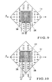
- Fig. 9 is a plan view showing an example of a variation of a pattern layout of the temperature sensor and the heater on a diaphragm portion of a flow velocity detector related to the present invention.
- Fig. 10 is a plan view showing an example of a variation of a pattern layout of the temperature sensor and the heater on a diaphragm portion of a flow velocity detector related to the present invention.
- Fig. 11 is a diagram showing a comparison of the flow rate-sensor output characteristics of a flow velocity detector related to the conventional art and the present invention.
- Fig. 12 is a plan view of a diaphragm portion of a conventional flow velocity detector.
- Fig.13 is a sectional side elevation showing an approximate cross section structure of a conventional flow velocity detector.
- Fig.1 is a perspective diagram showing one embodiment of a flow velocity detector related to the present invention.
- Fig. 2 is an expanded sectional view of a central part of a diaphragm portion of a flow velocity detector of Fig. 1 as seen from a lateral direction along a flow direction of a detected fluid.
- Fig. 1 Fig. 2, since the same symbols as in Fig. 12, Fig. 13 show the same constituting elements, those descriptions are omitted.
- an upstream side temperature sensor 3U1 and a downstream side temperature sensor 3D1 are disposed on both sides of a heater 2-1, and a recessed and projected direction of a comb tooth-shape of each temperature sensor 3U1, 3D1 is positioned approximately in parallel with the flow direction A of a detected fluid.
- Each temperature sensor 3U1, 3D1 is in such a zigzag arrangement, with a plurality of connections of the cranks, that a going and a return are in parallel with each other, like having traced a contour of a comb tooth-shape. Such a shape will be hereinafter referred to as a comb tooth-shape.
- each temperature sensor 3U1, 3D1 is positioned with the purpose that a long parallel portion which is facing and positioned in a crank shape, namely an extended direction of a comb tooth, will be in parallel with the flow direction of a detected fluid.
- each long portionsparallel to each other of crank shape each has substantially equal length, the short portion, which connects an adjacent long portion crossing at right angles at the edge portion of a long portion, positioned to be even on the same straight line.
- each temperature sensor 3U1, 3D1 makes the main extension of the comb tooth to be the pitch direction, which is positioned so that it crosses the flow direction of a detected fluid.
- symbol 6 in Fig. 1 is an ambient temperature sensor (a temperature sensor) formed at the edge portion of the substrate 1.
- a cavity 1-2 is formed in the like manner as a conventional flow velocity detector shown in Fig. 13. Because the constitution (structure, material, manufacturing method, signal processing method) other than the pattern layout of each temperature sensor 3U1, 3D1 is disclosed by the above-mentioned Official Gazettes of the Japanese Patent Publication No. Hei 4-74672, Japanese Patent Publication No. Hei 6-68451, Japanese Patent Application Laid Open No. Sho 61-88532, etc., description in detail may be omitted.
- each temperature sensor 3U, 3D consisting of metals
- the thermal conductivity of each temperature sensor 3U, 3D is far greater than the thermal conductivity of a diaphragm portion 1-1 consisting of insulating material
- the heat transfer condition is greatly controlled by the pattern shape of each temperature sensor 3U, 3D. Therefore, the heat from the heater 2-1 heats the crank-shaped connection parts J (refer to Fig. 3) of each temperature sensor 3U1, 3D1 formed in a comb tooth-shape, and further transfers through straight line parts S along the crank shapes of the connection parts J in the direction approximately in parallel with the flow direction of the detected fluid.
- the heat from the heater 2-1 effectively reaches the parts far from the heater 2-1 of each temperature sensor 3U1, 3D1.
- the heat association between the heater 2-1 and each temperature sensor 3U1, 3D1 becomes greater, making it possible to detect a high flow rate. It is desirable that the heater 2-1 and the crank-shaped connection parts J of each temperature sensor 3U1, 3D1 be positioned as near as possible to each other.
- the temperature of each temperature sensor 3U1, 3D1 is hard to be saturated, making it possible to detect a high flow rate.
- this is effective for the temperature saturation measures of the upstream side temperature sensor 3U1 in particular.
- the power consumption of the heater 2-1 increases incrementally .
- the flow rate-sensor output characteristics of this instance is shown in Fig. 11 as characteristics II. In the conventional characteristics I, the sensor output has been saturated from the neighborhood of 20 m/s. However, in the characteristics II by the present embodiment, even if 20 m/s is exceeded, the sensor output varies depending on flow rate, and it is recognized that the detection of a high flow rate is made possible.
- each temperature sensor 3U0, 3D0 the heat from the heater 2-1 is transferred through the straight line parts S of the side adjacent to the heater 2-1 in a direction approximately perpendicular to the flow direction of the detected fluid, not from the crank shaped connection parts J of each temperature sensor 3U0, 3D0 formed in comb tooth-shape, and said heat escapes toward the edge portion in a direction perpendicular to the flow of the diaphragm portion 1-1, and said heat is not effectively transferred to the parts far from the heater 2-1 of each temperature sensor 3U0, 3D0.
- the heat from the heater 2-1 is effectively transferred to the parts far from the heater 2-1 of each temperature sensor 3U1, 3D1, the heat association between the heater 2-1 and each temperature sensor 3U1, 3D1 becomes greater, making it possible to detect a high flow rate.
- Fig. 4 - Fig. 10 The examples of the variations of the pattern layout are shown in Fig. 4 - Fig. 10.
- the heater 2-2 with the recessed and projected direction of a comb tooth-shape is positioned approximately parallel to the flow direction A of the detected fluid.
- parts of the respective irregularities of these comb tooth-shapes of the heater 2-3 and each temperature sensor 3U3, 3D3 are grouped together and positioned in such a way that they cut into each other.
- part of the heater 2-5 is extended to surround each temperature sensor 3U4, 3D4 on three sides.
- part of the heater 2-6 is extended to surround each temperature sensor 3U4, 3D4 on four sides.
- each temperature sensor 3U, 3D the signal derivation parts of each temperature sensor 3U, 3D are provided in the position farthest from the heater 2. As thus described, by providing the signal derivation parts of each temperature sensor 3U, 3D at the positions farthest from the heater 2, every effort is made to minimize the heat quantity escaping to the substrate 1 in the outside of the diaphragm portion 1-1 through the signal derivation parts of each temperature sensor 3U, 3D.
- each temperature sensor 3U, 3D Since the quantity of heat moving by the thermal conductivity is in proportion to the temperature difference, the signal derivation parts of each temperature sensor 3U, 3D will be able to make the temperature difference small and reduce the heat escape, when the parts having lower temperature apart from the heater 2 and the substrate 1 are connected, instead of connecting high temperature parts close to the heater 2 and the substrate 1 having approximately ambient temperature.
- the flow rate-sensor output characteristics, when the pattern layout of Fig. 6 is applied are shown as characteristics III in Fig. 11, and the flow rate-sensor output characteristics, when the pattern layout of Fig. 9 is applied, are shown as characteristics IV in Fig. 11.
- the sensitivity at a high flow rate becomes greater in the characteristics III, rather than in the characteristics II, and in the characteristics IV, rather than in the characteristics III.
- the pattern width of each temperature sensor 3U, 3D is made to be narrower than the pattern width of the heater 2, it is also acceptable as the constitution to make the pattern width of both to be the same, or to make the pattern width of the heater 2 narrower than the pattern width of each temperature sensor 3U, 3D.
- the pattern width of the heater 2 is made to be wide in terms of reliability, since an electric current flows in larger quantity in the heater 2 as compared with each temperature sensor 3U, 3D, and the pattern width of each temperature sensor 3U, 3D is made to be as narrow as possible for increasing the sensitivity and for increasing the resistance value.
- each temperature sensor 3U, 3D For the detection of a high flow rate, although it is assumed to be advisable that the thickness of each temperature sensor 3U, 3D is made thick to increase the heat transfer efficiency and to increase the heat capacity, the increase in thickness will cause the increase in electric power consumption and the response speed will become slow.
- the heat transfer efficiency can be increased without making the thickness of each temperature sensor 3U, 3D to be thick, the power consumption will not become larger than necessary, and the response speed will not become slow.
- the heat from the heater heats the crank-shaped connection parts of the temperature sensors formed in comb tooth-shape, and then transfers through straight line parts along the crank-shapes of the temperature sensors in a direction approximately in parallel with the flow direction of the detected fluid, and it will become possible to detect a high flow rate without causing any difficulty in mass production, increasing the heat association between the heater and the temperature sensors.
Landscapes
- Physics & Mathematics (AREA)
- Fluid Mechanics (AREA)
- General Physics & Mathematics (AREA)
- Measuring Volume Flow (AREA)
Abstract
Description
with a plurality of connections of the cranks, that a going and a return are in parallel with each other, like having traced a contour of a comb tooth-shape. Such a shape will be hereinafter referred to as a comb tooth-shape. Therefore, each temperature sensor 3U1, 3D1, is positioned with the purpose that a long parallel portion which is facing and positioned in a crank shape, namely an extended direction of a comb tooth, will be in parallel with the flow direction of a detected fluid. In addition, as for the long portionsparallel to each other of crank shape, each has substantially equal length, the short portion, which connects an adjacent long portion crossing at right angles at the edge portion of a long portion, positioned to be even on the same straight line. In other words, each temperature sensor 3U1, 3D1 makes the main extension of the comb tooth to be the pitch direction, which is positioned so that it crosses the flow direction of a detected fluid.
is positioned approximately parallel to the flow direction A of the detected fluid. In Fig. 6, parts of the respective irregularities of these comb tooth-shapes of the heater 2-3 and each temperature sensor 3U3, 3D3 are grouped together and positioned in such a way that they cut into each other.
Claims (10)
- A flow velocity detector characterized by comprising:a diaphragm portion being formed in a thin-wall shape providing a cavity in a part of the substrate, a heater formed in said diaphragm portion, and temperature sensors formed on both sides of said heater;said temperature sensors formed in comb tooth-shape connecting a plurality of crank shapes, and said temperature sensor with the recessed and projected direction of this comb tooth-shape positioned approximately in parallel with the flow direction of the detected fluid.
- A flow velocity detector according to claim 1,wherein said heater is formed to be in comb tooth-shape connecting a plurality of crank shapes,said heater with the recessed and projected direction of this comb tooth-shape being placed approximately in parallel with the flow direction of the detected fluid.
- A flow velocity detector according to claim 2,
wherein at least parts of the respective irregularities of these comb tooth-shapes of said temperature sensor and said heater are positioned in such a way that they cut into each other. - A flow velocity detector according to claim 3,
wherein convexed parts cutting into said temperature sensor side of the comb tooth-shapes of said heater are made to be wide in the flow direction of said detected fluid. - A flow velocity detector according to claim 1,
wherein said heater is extended to surround at least part of the periphery of said temperature sensor. - A flow velocity detector according to claim 2,
wherein said heater is extended to surround at least part of the periphery of said temperature sensor. - A flow velocity detector according to claim 3,
wherein said heater is extended to surround at least part of the periphery of said temperature sensor. - A flow velocity detector according to claim 4,
wherein said heater is extended to surround at least part of the periphery of said temperature sensor. - A flow velocity detector according to claim 1,
wherein signal derivation parts from said temperature sensor are provided in the position farthest from said heater. - A flow velocity detector according to claim 1,
wherein each of said temperature sensor's long portions of crank shape parallel to each other have substantially equal length, and the short portions connecting adjacent long portions crossing at right angles at the edge portion of a long portion is positioned evenly on the same straight line.
Applications Claiming Priority (3)
| Application Number | Priority Date | Filing Date | Title |
|---|---|---|---|
| JP16637299 | 1999-06-14 | ||
| JP16637299 | 1999-06-14 | ||
| PCT/JP2000/003845 WO2000077478A1 (en) | 1999-06-14 | 2000-06-14 | Flow velocity detector |
Publications (2)
| Publication Number | Publication Date |
|---|---|
| EP1124114A1 true EP1124114A1 (en) | 2001-08-16 |
| EP1124114A4 EP1124114A4 (en) | 2007-01-03 |
Family
ID=15830198
Family Applications (1)
| Application Number | Title | Priority Date | Filing Date |
|---|---|---|---|
| EP00937213A Withdrawn EP1124114A4 (en) | 1999-06-14 | 2000-06-14 | Flow velocity detector |
Country Status (7)
| Country | Link |
|---|---|
| US (1) | US6536274B1 (en) |
| EP (1) | EP1124114A4 (en) |
| JP (1) | JP4271888B2 (en) |
| KR (1) | KR100524021B1 (en) |
| CN (1) | CN1209603C (en) |
| AU (1) | AU5246800A (en) |
| WO (1) | WO2000077478A1 (en) |
Cited By (2)
| Publication number | Priority date | Publication date | Assignee | Title |
|---|---|---|---|---|
| EP2505970A1 (en) * | 2011-03-31 | 2012-10-03 | JUMO GmbH & Co. KG | Calorimetric sensor |
| EP2711672A1 (en) | 2012-09-25 | 2014-03-26 | Honeywell Technologies Sarl | Flow detector |
Families Citing this family (13)
| Publication number | Priority date | Publication date | Assignee | Title |
|---|---|---|---|---|
| JP3658321B2 (en) * | 2000-12-28 | 2005-06-08 | オムロン株式会社 | Flow sensor and manufacturing method thereof |
| JP2003035580A (en) * | 2001-07-19 | 2003-02-07 | Denso Corp | Flow sensor |
| JP3905793B2 (en) | 2002-06-04 | 2007-04-18 | 株式会社山武 | Adsorption confirmation sensor |
| DE10230198A1 (en) * | 2002-07-05 | 2004-01-22 | Robert Bosch Gmbh | Sensor with a heater and method |
| US7131766B2 (en) * | 2003-07-16 | 2006-11-07 | Delphi Technologies, Inc. | Temperature sensor apparatus and method |
| JP4120637B2 (en) * | 2004-11-30 | 2008-07-16 | オムロン株式会社 | Flow velocity measuring device |
| JP4850105B2 (en) * | 2007-03-23 | 2012-01-11 | 日立オートモティブシステムズ株式会社 | Thermal flow meter |
| US8132455B2 (en) * | 2009-08-10 | 2012-03-13 | Chih-Chang Chen | Robust micromachined thermal mass flow sensor with double side passivated polyimide membrane |
| JP5683192B2 (en) | 2010-09-30 | 2015-03-11 | 日立オートモティブシステムズ株式会社 | Thermal flow sensor |
| US8286478B2 (en) * | 2010-12-15 | 2012-10-16 | Honeywell International Inc. | Sensor bridge with thermally isolating apertures |
| US9354095B2 (en) | 2012-10-02 | 2016-05-31 | Honeywell International Inc. | Modular flow sensor |
| US9612146B2 (en) | 2014-02-07 | 2017-04-04 | Honeywell International, Inc. | Airflow sensor with dust reduction |
| EP3410930B1 (en) | 2016-02-04 | 2019-11-27 | Medyria AG | Sensor arrangement and catheter comprising a sensor arrangement |
Family Cites Families (6)
| Publication number | Priority date | Publication date | Assignee | Title |
|---|---|---|---|---|
| US4651564A (en) * | 1982-09-30 | 1987-03-24 | Honeywell Inc. | Semiconductor device |
| DE3606853A1 (en) * | 1986-03-03 | 1987-09-10 | Vdo Schindling | MEASURING PROBE |
| US5393351A (en) * | 1993-01-13 | 1995-02-28 | The United States Of America As Represented By The Secretary Of Commerce | Multilayer film multijunction thermal converters |
| DE9409318U1 (en) * | 1994-06-08 | 1994-08-11 | Murata Elektronik GmbH, 90441 Nürnberg | Flow sensor |
| DE19520777C1 (en) * | 1995-06-07 | 1996-08-29 | Inst Physikalische Hochtech Ev | Temperature-compensated micro-flowmeter with mirror-symmetrical layout |
| US5852239A (en) * | 1996-06-12 | 1998-12-22 | Ricoh Company, Ltd. | Flow sensor having an intermediate heater between two temperature-sensing heating portions |
-
2000
- 2000-06-14 EP EP00937213A patent/EP1124114A4/en not_active Withdrawn
- 2000-06-14 JP JP2001503488A patent/JP4271888B2/en not_active Expired - Fee Related
- 2000-06-14 WO PCT/JP2000/003845 patent/WO2000077478A1/en not_active Ceased
- 2000-06-14 KR KR10-2001-7001943A patent/KR100524021B1/en not_active Expired - Lifetime
- 2000-06-14 AU AU52468/00A patent/AU5246800A/en not_active Abandoned
- 2000-06-14 US US09/762,989 patent/US6536274B1/en not_active Expired - Lifetime
- 2000-06-14 CN CN00801406.XA patent/CN1209603C/en not_active Expired - Lifetime
Cited By (2)
| Publication number | Priority date | Publication date | Assignee | Title |
|---|---|---|---|---|
| EP2505970A1 (en) * | 2011-03-31 | 2012-10-03 | JUMO GmbH & Co. KG | Calorimetric sensor |
| EP2711672A1 (en) | 2012-09-25 | 2014-03-26 | Honeywell Technologies Sarl | Flow detector |
Also Published As
| Publication number | Publication date |
|---|---|
| WO2000077478A1 (en) | 2000-12-21 |
| JP4271888B2 (en) | 2009-06-03 |
| CN1209603C (en) | 2005-07-06 |
| EP1124114A4 (en) | 2007-01-03 |
| KR20010103568A (en) | 2001-11-23 |
| CN1318147A (en) | 2001-10-17 |
| US6536274B1 (en) | 2003-03-25 |
| AU5246800A (en) | 2001-01-02 |
| KR100524021B1 (en) | 2005-10-26 |
Similar Documents
| Publication | Publication Date | Title |
|---|---|---|
| US6536274B1 (en) | Flow velocity detector | |
| US6470742B1 (en) | Flow sensor | |
| EP2600121A1 (en) | Thermal flow meter | |
| US6615655B1 (en) | Heat-sensitive type flow rate detecting element and holder therefor | |
| JPWO2000077478A1 (en) | Flow Detector | |
| JP3470881B2 (en) | Micro flow sensor | |
| US5060511A (en) | Intake air quantity measuring apparatus | |
| JP3831524B2 (en) | Infrared gas analyzer flow detection element and method of manufacturing the same | |
| JP3687724B2 (en) | Heater for flow meter | |
| JP3589083B2 (en) | Thermal flow sensor | |
| US6250150B1 (en) | Sensor employing heating element with low density at the center and high density at the end thereof | |
| JP2020122747A (en) | Detector | |
| EP0452134A2 (en) | Diaphragm-type sensor | |
| JP2007101561A (en) | Flow rate detector | |
| JP2562076B2 (en) | Flow sensor | |
| CN117342517B (en) | MEMS hot-film flow sensor chip and preparation method thereof | |
| JP2602117B2 (en) | Flow sensor | |
| JPH0422269Y2 (en) | ||
| JP3316740B2 (en) | Flow detection element | |
| JP2005172445A (en) | Flow sensor | |
| JPH04102023A (en) | Flow speed sensor | |
| JP2002286519A (en) | Thermal flow sensor | |
| JP2001153707A (en) | Flow sensor | |
| JP2000227352A (en) | Thermal flow sensor | |
| EP4464990A2 (en) | Thermopile-based flow sensing apparatus with electrostatic protection |
Legal Events
| Date | Code | Title | Description |
|---|---|---|---|
| PUAI | Public reference made under article 153(3) epc to a published international application that has entered the european phase |
Free format text: ORIGINAL CODE: 0009012 |
|
| 17P | Request for examination filed |
Effective date: 20010310 |
|
| AK | Designated contracting states |
Kind code of ref document: A1 Designated state(s): AT BE CH CY DE DK ES FI FR GB GR IE IT LI LU MC NL PT |
|
| AX | Request for extension of the european patent |
Free format text: AL;LT;LV;MK;RO;SI |
|
| RBV | Designated contracting states (corrected) |
Designated state(s): DE FR GB NL |
|
| A4 | Supplementary search report drawn up and despatched |
Effective date: 20061206 |
|
| RIC1 | Information provided on ipc code assigned before grant |
Ipc: G01F 1/684 20060101AFI20061130BHEP Ipc: G01F 1/692 20060101ALI20061130BHEP |
|
| 17Q | First examination report despatched |
Effective date: 20070330 |
|
| RAP1 | Party data changed (applicant data changed or rights of an application transferred) |
Owner name: AZBIL CORPORATION |
|
| STAA | Information on the status of an ep patent application or granted ep patent |
Free format text: STATUS: THE APPLICATION IS DEEMED TO BE WITHDRAWN |
|
| 18D | Application deemed to be withdrawn |
Effective date: 20170420 |