EP1124004B1 - Pulp screening device - Google Patents
Pulp screening device Download PDFInfo
- Publication number
- EP1124004B1 EP1124004B1 EP01102170A EP01102170A EP1124004B1 EP 1124004 B1 EP1124004 B1 EP 1124004B1 EP 01102170 A EP01102170 A EP 01102170A EP 01102170 A EP01102170 A EP 01102170A EP 1124004 B1 EP1124004 B1 EP 1124004B1
- Authority
- EP
- European Patent Office
- Prior art keywords
- pulp
- screening device
- vane
- screen cylinder
- screen
- Prior art date
- Legal status (The legal status is an assumption and is not a legal conclusion. Google has not performed a legal analysis and makes no representation as to the accuracy of the status listed.)
- Expired - Lifetime
Links
Images


Classifications
-
- D—TEXTILES; PAPER
- D21—PAPER-MAKING; PRODUCTION OF CELLULOSE
- D21D—TREATMENT OF THE MATERIALS BEFORE PASSING TO THE PAPER-MAKING MACHINE
- D21D5/00—Purification of the pulp suspension by mechanical means; Apparatus therefor
- D21D5/02—Straining or screening the pulp
- D21D5/06—Rotary screen-drums
-
- D—TEXTILES; PAPER
- D21—PAPER-MAKING; PRODUCTION OF CELLULOSE
- D21D—TREATMENT OF THE MATERIALS BEFORE PASSING TO THE PAPER-MAKING MACHINE
- D21D5/00—Purification of the pulp suspension by mechanical means; Apparatus therefor
- D21D5/02—Straining or screening the pulp
- D21D5/023—Stationary screen-drums
- D21D5/026—Stationary screen-drums with rotating cleaning foils
-
- D—TEXTILES; PAPER
- D21—PAPER-MAKING; PRODUCTION OF CELLULOSE
- D21D—TREATMENT OF THE MATERIALS BEFORE PASSING TO THE PAPER-MAKING MACHINE
- D21D5/00—Purification of the pulp suspension by mechanical means; Apparatus therefor
- D21D5/02—Straining or screening the pulp
-
- D—TEXTILES; PAPER
- D21—PAPER-MAKING; PRODUCTION OF CELLULOSE
- D21D—TREATMENT OF THE MATERIALS BEFORE PASSING TO THE PAPER-MAKING MACHINE
- D21D5/00—Purification of the pulp suspension by mechanical means; Apparatus therefor
- D21D5/02—Straining or screening the pulp
- D21D5/16—Cylinders and plates for screens
Definitions
- the present invention relates to a pulp screening device for separating good-quality fibers and foreign objects in paper pulp.
- a pulp screening device On the upstream side of a paper machine, there is provided a pulp screening device (pulp screen).
- the pulp screening device is a device for screening and separating good-quality fibers and foreign objects in paper pulp (i.e., a pulp suspension with a pulp density of 0.2 to 5 %) with a screen cylinder thereof.
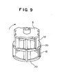
- the pulp screening device is equipped with one or two screen cylinders.
- a pulp suspension is fed to the pulp screening device by a pump. As illustrated in Figs. 28 and 29, the pulp suspension flows in a tangential direction through the entrance 2 of a cylindrical container 17, and advances in an annular flow passage 4, formed by an inner casing 3 and the inner wall of the container 17.
- an annular flow passage 4 formed by an inner casing 3 and the inner wall of the container 17.
- heavy foreign objects such as sand, etc.
- a cover 19 is provided on the upper surface of the container 17 so that the device can be operated under pressure.
- a cylindrical screen cylinder 1 is disposed inside the inner casing 3.
- the upper portion of the screen cylinder 1 is fixedly attached to the inner casing 3, and this screen cylinder 1 partitions the inner side of the inner casing 3 into an agitation chamber 7 and an exit chamber 14.
- the pulp flowing in the flow passage 4 first flows in the annular agitation chamber 7 formed inside the screen cylinder 1.
- a large number of slits of width 0.15 to 0.5 mm or holes of diameter 0.2 to 4.8 mm are provided in the peripheral surface of the screen cylinder 1, and the pulp is filtered and sorted by these slits or holes when flowing downward along the agitation chamber 7. That is, the good-quality fibers that can pass through the slits or holes in the peripheral surface of the screen cylinder 1 are discharged from an exit 9 via the exit chamber 14, while the foreign objects of sizes that cannot pass through the slits or holes in the screen cylinder, as they are, flow downward along the agitation chamber 7 and are discharged from a reject exit 10.
- a rotor 6 is disposed within the agitation chamber 7.
- the rotor 6 is hung from the upper portion of a main shaft 11 and is equipped with a plurality of vanes 20 at equal spaces in the circumferential direction.
- the vane 20 is positioned, holing a predetermined space (2.5 to 8 mm) from the inner peripheral surface of the screen cylinder 1.
- the main shaft 11 is supported by bearings so that it is free to rotate, and is driven to rotate by an electric motor 13 through a V-pulley (not shown) mounted on the lower end portion thereof. If the rotor 13 rotates and therefore the vanes 20 revolve within the annular agitation chamber 7, the pulp suspension within the agitation chamber 7 is agitated. The foreign objects in the pulp are separated, and tangled fibers are untangled. As a result, clogging of the slits or holes in the screen cylinder 1 is prevented.
- Fig. 30 shows how clogging of the slits or holes in the screen cylinder 1 is prevented by the vanes 20.
- the vane 20 revolves along the surface of the screen cylinder 1 at high speeds (10 to 30 m/s), holding a constant space from the cylinder surface.
- negative pressure is developed between the vane 20 and the screen cylinder 1, as shown in Fig. 30B.
- the suction force developed by this negative pressure, causes the solution to flow backward into the agitation chamber 7 and therefore the tangled fibers or foreign objects, blocking holes 100 in the surface of the screen cylinder 1, are removed.
- the pulp suspension After passage of the vane 20, the pulp suspension will flow from the agitation chamber 7 into the exit chamber 14 again, and the holes 100 in the screen cylinder 1 will be clogged with tangled fibers and foreign objects. However, the tangled fibers, etc., newly blocking the holes 100, are removed by the negative pressure produced by passage of the next vane 20. In the conventional pulp screening device, clogging of the holes in the screen cylinder 1 is prevented by repeating the aforementioned operation.
- Fig. 31 shows a sectional view of the configuration of the hole 100 in the screen cylinder 1.
- the hole 100 is circular in shape, and a chamfered face 101 in the form of a dish is formed coaxially at the inlet of the hole 100 (on the side of the agitation chamber 7) .
- a turbulence separating vortex
- clogging of the hole 100 is suppressed by the turbulence S.
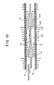
- screen plates 1 of cross sections such as those shown in Figs. 32 and 33.
- trapezoidal grooves 111 are formed in the axial direction of the screen plate 1 (perpendicular to the paper surface) and forms a plurality of holes 110 at the bottoms of the grooves 33.
- an axial waveform is formed on the peripheral surface of the screen cylinder 1, and a plurality of holes 120 are bored axially in the inclined portion 121 of the waveform.
- Fig. 34 shows a sectional view of the conventional pulp screening device with two inner and outer screen cylinders
- Fig. 35 shows a sectional view taken substantially along line E-E in Fig 34. Note that the same reference numerals will be applied to the same parts as the aforementioned conventional pulp screening device having a single screen cylinder.
- a pulp suspension flows in a tangential direction through the entrance 2 of a cylindrical container 17 and circulates through an annular flow passage 4.
- heavy foreign objects such as sand, etc., are discharged outside the device from a trap 5 provided in the tangential direction of the flow passage 4, and the remaining pulp suspension flows from the flow passage 4 to inside an inner casing 3.
- Cylindrical screen cylinders 1a and 1b are disposed inside the inner casing 3. These screen cylinders 1a and 1b partition the inside of the inner casing 3 into an agitation chamber 7 and exit chambers 14a, 14b.
- the pulp suspension flowing in the flow passage 4 first flows in the annular agitation chamber 7, formed between the screen cylinders 1a and 1b.
- part of the pulp passes through the inner screen cylinder 1b and is filtered and sorted in the inner exit chamber 14a.
- the remaining pulp passes through the outer screen cylinder 1, and is filtered and sorted in the outer exit chamber 14.
- a plurality of outer vanes 20a are disposed in opposition to the outer screen cylinder 1a and a plurality of inner vanes 20b are disposed in opposition to the inner screen cylinder 1b.
- the vanes 20a, 20b are fixedly attached to a rotor 6 hung from the upper portion of a main shaft 11.
- the outer vanes 20a are disposed at equal spaces in the circumferential direction, holding a constant space (2.5 to 8 mm) from the outer screen cylinder 1a.
- the inner vanes 20b are disposed at equal spaces in the circumferential direction, holing the constant space (2.5 to 8 mm) from the inner screen cylinder 1b.
- the main shaft 11 is freely rotatably supported by bearings and is driven to rotate by an electric motor (not shown) through a V-pulley 18 mounted on the lower end portion thereof. If the rotor 13 rotates and therefore the vanes 20a, 20b revolve within the annular agitation chamber 7, the pulp suspension within the agitation chamber 7 is agitated. The foreign objects in the pulp are separated, and tangled fibers are untangled. As a result, clogging of the slits or holes in the screen cylinders 1a, 1b is prevented.
- the conventional pulp screening device shown in Figs. 28 and 29 has a limit to its processing ability since it has only a single screen cylinder 1.
- the revolution flow caused by the vane 20 becomes faster as it is near the surface of the vane 20 and slower as it is away from the vane surface. Therefore, the efficiency of cleaning the surface of the screen cylinder 1 is low, and there is a problem that the passage amount of the pulp will be reduced.
- the surface of the vane 20 remote from the surface of the screen cylinder 1 wastefully consumes the power required for friction, because it makes no contribution to the cleaning of the surface of the screen cylinder 1.
- the speed of the revolution flow, developed by revolution of the vanes 20a and 20b, is slower at the inner screen cylinder 1b than at the outer screen cylinder 1a because of the difference in diameter between the inner and outer screen cylinders 1a and 1b.
- the pressure acting on the inner screen cylinder 1b is lower than that acting on the outer screen cylinder 1a because of a difference in centrifugal force. Therefore, the outer screen cylinder 1a tends to pass the pulp to more than the effective area of the screen cylinder 1a, whereas the inner screen cylinder 1b tends to pass the pulp to less than the effective area of the screen cylinder 1b.
- the conventional pulp screening device has the problem that the quantity of pulp to be passed will be limited by clogging of the holes in the screen cylinder 1.
- the clogging of the holes in the screen cylinder 1 results from the configuration of the holes formed in the screen cylinder 1.
- the turbulence S (see Figs. 31 to 33), developed at the inlet of the hole by the revolution flow resulting from revolution of the vane 20, has the effect of preventing the hole from being clogged.
- the strength of the turbulence S is affected by the configuration of the front edge of the hole (located on the upstream side of the revolution flow) .
- the difficulty for tangled fibers to be caught, and the ease of removing foreign objects are affected by the configuration of the rear edge of the hole (located on the downstream side of the revolution flow).
- the turbulence S develops at the inclined surface, on the upstream side, of the hole 100 formed by the dish-shaped chambered surface 101, but the developed vertex S is weak because the inclined surface is gentle. Therefore, the turbulence S is less liable to reach the front edge 102 or rear edge 103 of the hole 100. Because of this, the effect of preventing clogging by the turbulence S is low.
- the dish-shaped chambered surface 101 is formed coaxially with the hole 100, room for forming the dish-shaped chambered surface is required and the number of holes per unit area is thus limited. Because of this, there is a limit to increasing the quantity of pulp to be passed, by increasing the number of holes 100.
- the turbulence S which develops is strong, because the vertical portion of the trapezoidal groove 111 is located on the upstream side of flow.
- the vortex S developed is less likely to reach the front edge 112 and therefore the effect of preventing clogging of the hole 110 is low.
- the rear edge 113 is positioned at the groove bottom portion and is away from the inclined portion 114, separation of tangled fibers, etc, caught in the hole 100, is not easy.
- the hole 110 can be disposed only in the bottom portion of the trapezoidal groove 111, the number of holes per unit area is also limited.
- the turbulence S develops at the vertex of the waveform formed on the surface of the screen cylinder 1.
- the front edge 122 of the hole 120 is far from the vertex of the waveform and the front and rear edges 122, 123 are at the inclined portion 121 of the waveform. Therefore, the turbulence S is less likely to reach the edges 122, 123, and the effect of preventing clogging of holes by the turbulence S is thus low.
- the rear edge 123 has an acute angle, separation of a lump of pulp, etc., caught on the edge, is not easy.
- the number of holes per unit area is limited, because the hole 120 can be disposed only in the inclined portion 121 of the waveform.
- a screening device which comprises inner and outer cylindrical screens, at least two vanes of streamlined cross-sectional configuration extending into the space between the screens, and a pair of annular chambers, one disposed outside of the outer screen and one disposed within the inner screen.
- the device further comprises means for withdrawing screened suspension from the chambers, and means for withdrawing rejected material from the space between the screens.
- U.S. Patent No. 5,497,886 discloses a screening apparatus for papermaking pulp, the apparatus comprising a screening chamber defined between a stationary screen member and a rotor, an accepts chamber outboard of the screening chamber, as well as a plurality of half-foil members disposed on the outer surface of the rotor.
- a rejects discharge is provided downstream of the screening chamber, and an accepts discharge is provided in the accepts chamber.
- the present invention which is defined in claim 1 below, has been made in view of the problems found in the prior art. Accordingly, it is the primary object of the present invention to provide a pulp screening device that power, by preventing clogging of a screen cylinder.
- a pulp screening device comprising:
- the cross section of an inner discharge tube at a point where the inner discharge tube joins an outer discharge tube is set greater than the cross section of the outer discharge tube, pulp being passed through the inner screen cylinder and flowing in the inner discharge tube and also being passed through the outer screen cylinder and flowing in the outer discharge tube.
- the agitation chamber can be practically partitioned in the circumferential direction, by providing the vanes which revolve within the agitation chamber formed between the inner and outer screen cylinders, holding a predetermined small space from each of the inner and outer screen cylinders.
- the internal pressure within the agitation chamber becomes higher, as the revolution speed of pulp is increased. Therefore, the separation and agitation of foreign objects and lumps of pulp are accelerated, and clogging of the screen cylinders is prevented and the quantity of pulp to be passed is increased.
- the distance between the inner and outer screen cylinders can be shortened by sharing a single vane with the inner and outer screen cylinders.
- the revolution-direction front portion of the vane has a wall face extending radially toward the peripheral surfaces of the inner and outer screen cylinders.
- the wall face is formed at a right or acute angle to the direction of revolution.
- the cross section of the vane is formed so that the spacing between the cross section and each of the inner and outer screen cylinders widens gradually from the wall face in the direction of revolution.
- the cross section of the vane is formed into the shape of a wedge extending at an acute angle from a revolution-direction tip end to both proximity portions closest to the inner and outer screen cylinders.
- a distance from the tip end to both proximity portions is set to two to five times a distance between both proximity portions.
- the aforementioned tip end is disposed at a center between the inner and outer screen cylinders, or at a position offset from the center toward the outer screen cylinder.
- the cross section of the vane is formed so that the spacing between the cross section and each of the inner and outer screen cylinders widens gradually from both proximity portions in the direction of revolution.
- a pulp screening device may comprise:
- Another pulp screening device may comprise:
- Figs. 1 through 5 show a pulp screening device constructed according to a first embodiment of the present invention.
- the pulp screening device will hereinafter be described with reference to Figs. 1 to 5.
- Fig. 1 shows a part-sectional plan view of the construction of the pulp screening device.
- Fig. 2 shows a part-sectional side view taken in the direction of arrow A of Fig. 1.
- Fig. 3 shows a perspective view of the construction of the rotor of the pulp screening device.
- Fig. 4 shows a sectional view of the configuration of the common vane of the pulp screening device of the first embodiment.
- Fig. 5 shows a diagram for explaining the operational effect of the pulp screening device. Note that the same reference numerals will be applied to the same parts as the aforementioned conventional pulp screening device.
- the pulp screening device has two screen cylinders 1a, 1b differing in diameter, as illustrated in Figs. 1 and 2 .
- An agitation chamber 7 is formed between the screen cylinders 1a and 1b.
- An outer exit chamber 14a is formed outside the outer screen cylinder 1a, and an inner exit chamber 14b is formed inside the inner screen cylinder 1b.
- a pulp suspension fed from a pump (not shown), first flows in a tangential direction through the entrance 2 of a cylindrical container 17 and circulates through an annular flow passage 4, formed by an inner casing 3 and the inner wall of the container 17.
- an annular flow passage 4 formed by an inner casing 3 and the inner wall of the container 17.
- heavy foreign objects such as sand, etc.
- the remaining pulp flows from the flow passage 4 into the agitation chamber 7.
- the screen cylinders 1a, 1b are provided in the peripheral surfaces thereof with a large number of slits of width 0.15 to 0.5 mm or holes of diameter 0.2 to 4.8 mm. Because of this, when the pulp suspension is flowing downward along the agitation chamber 7, part of the pulp passes through the inner screen cylinder 1b and is filtered and sorted in the inner exit chamber 14b, while the remaining pulp passes through the outer screen cylinder 1a and is filtered and sorted in the outer exit chamber 14a. On the other hand, the foreign objects of sizes that cannot pass through the screen cylinders 1a, 1b, as they are, flow downward along the agitation chamber 7 and are discharged from a reject exit 10 via a reject receiver 25.
- the inner exit chamber 14b and the outer exit chamber 14a are completely partitioned, and the pulp suspension, sorted in the outer exited chamber 14a from the agitation chamber 7, passes through an outer discharge tube 16 and is discharged from the exit 9.
- the pulp suspension sorted in the inner exit chamber 14b passes through an inner discharge tube 15 provided in the outer discharge tube 16, and is discharged from the exit 9, joining the pulp suspension flowing from the outer exit chamber 14a into the discharge 16.
- the dimension of the cross section of the exit of the inner discharge tube 15 is set equal to or greater than the dimension of the cross section of the outer discharge tube 16 at a point where the outer discharge tube 16 joins the inner discharge tube 15.
- the bottom surface of the inner exit chamber 14b, the bottom surface of the outer exit chamber 14a, and the bottom surface of the reject receiver 25 are inclined downward toward the exits 9 and 10 in order to prevent deposition of the pulp.
- a cylindrical rotor 6 is hung from the upper portion of a main shaft 11 and disposed within the agitation chamber 7.
- the rotor 6 has a plurality of vanes 12 (hereinafter referred to as common vanes, because each vane in the first embodiment acts in common on the inner and outer screen cylinders) at its peripheral surface, as illustrated in Fig. 3.
- the common vanes 12 are interconnected at their lower ends by a connecting ring 30 and are disposed at equal spaces in the circumferential direction of the rotor 6. As illustrated in Figs.
- each common vane 12 is located within the agitation chamber 7, holding a predetermined space (preferably 2 to 6 mm) from the inner peripheral surface of the outer screen cylinder 1a and the predetermined space from the outer peripheral surface of the inner screen cylinder 1b.
- a predetermined space preferably 2 to 6 mm
- the agitation chamber 7 in the pulp screening device of the first embodiment is practically partitioned in the circumferential direction by the common vanes 12.
- the common vane 12 in the pulp screening device of the first embodiment has a front wall 201 and a deflection wall 202, as illustrated in Fig. 4.
- the front wall 201 extends from a tip end 205 in the direction opposite to the direction of revolution, and the deflection wall 202 is continuous to the front wall 201 and extends in the radial direction of the rotor 6 (perpendicular to the direction of revolution).
- the deflection wall 202 is jointed to a pair of rear curved faces 204 extending from a rear end 206 in the direction of revolution, and the joined portion forms an acute-angle edge 203.
- the spacing, within the agitation chamber 7, between the common vane 12 and the screen cylinder 1a or 1b becomes gradually narrower from the tip end 205 toward the rear direction and then becomes even narrower suddenly at the deflection wall 202 and narrowest at the edge 203.
- the spacing between the edge 203 and the screen cylinder 1a or 1b is set to the aforementioned predetermined space (preferably 2 to 6 mm) . Furthermore, the spacing widens gradually from the edge 203 to a rear end 206 (refer to Fig. 5A).
- the deflection wall 202 be concave and also preferable that the angle of deflection at the deflection wall 202 (which is an angle, indicated by ⁇ in Fig. 5A, which is formed by both the direction of revolution and the direction in which the deflection wall 202 extends) be 90 degrees or less.
- the pulp suspension fed from an upstream pump (not shown), first flows in a tangential direction through the entrance 2 of the container 17 and circulates through the flow passage 4.
- the pulp suspension is circulating the flow passage 4
- the heavy foreign objects in the pulp suspension such as sand, etc., are discharged outside the device from the trap 5 provided in the tangential direction opposite to the entrance 2, and the remaining pulp flows into the agitation chamber 7, formed between the screen cylinders 1a and 1b inside the inner casing 3.
- the pulp within the agitation chamber 7 flows in the direction opposite to the direction of revolution of the common vane 12, relative to the common vane 12.
- the common vane 12 is provided with the deflection wall 202 extending in the radial direction, the circumferential flow of the pulp strikes on the deflection wall 202 and is therefore changed to the radial flow.
- the flow of the pulp into the space between the screen cylinder 1a or 1b and the common vane 12 is suppressed. That is, the agitation chamber 7 is practically partitioned at the space between the screen cylinder 1a or 1b and the common vane 12, by the radial flow near the deflection wall 202.
- the agitation chamber 7 is practically partitioned into a plurality of parts in the circumferential direction by the radial flow of the pulp near the deflection walls 202. Therefore, the pulp, within the agitation chamber 7 partitioned into a plurality of parts, is pushed by the common vanes 12 and revolved in the circumferential direction at approximately the same speed as that of the common vane 12. Since the radial flow of the pulp toward the surface of the screen cylinder 1a or 1b is developed by the deflection wall 202, the internal pressure within the agitation chamber 7 rises greatly from the tip end 205 to the edge 203, as illustrated in Fig. 5B.
- the spacing between the screen cylinders 1a and 1b is approximately the same as the thickness of a single common vane 12, and is narrower, compared with the conventional pulp screening device provided with two screen cylinders (see Figs. 34 and 35). Therefore, the speed difference of the pulp between the inner and outer screen cylinders 1a and 1b is smaller compared with conventional pulp screening device, and the pressure difference developed by centrifugal force is also smaller compared with conventional pulp screening device.
- the pulp is inhibited from flowing into the screen cylinder 1a or 1b through the space between the surface of the screen cylinder 1a or 1b and the edge 203.
- the spacing between the surface of the screen cylinder 1a or 1b and the rear curved face 204 widens gradually. Therefore, as illustrated in Fig. 5B, the internal pressure within the agitation chamber 7 results in a great negative pressure, which causes the pulp suspension to flow backward from the exit chambers 14a, 14b into the agitation chamber 7. With the back flow of the pulp suspension, the lumps of pulp, etc., caught in the holes 100 of the screen cylinders 1a, 1b, are removed and the pulp density within the agitation chamber 7 is diluted.
- a static pressure component in the flow from the inner exit chamber 14b is increased and a static pressure component in the flow from the outer exit chamber 14a is conversely decreased, because the dimension of the cross section of the exit of the inner discharge tube 15 is set equal to or greater than the dimension of the cross section of the outer discharge tube 16 at a point where the outer discharge tube 16 joins the inner discharge tube 15.
- the pulp screening device of the first embodiment has the following advantages:
- a single common vane 12 is shared with the inner and outer screen cylinders 1a, 1b so that the distance between the screen cylinders can be reduced. Therefore, the speed difference of the pulp between the inner and outer screen cylinders 1a, 1b caused by the difference in diameter therebetween, and the pressure difference caused by centrifugal force, become smaller compared with conventional pulp screening device. As a result, the holes in the inner screen cylinder 1b are less likely to be clogged and a reduction in the quantity of pulp to be passed is prevented.
- the common vane 12 is provided with the deflection wall 202. Because of this, the agitation chamber 7 is practically partitioned into a plurality of parts by the radial flow of the pulp near the deflection walls 202. This causes the revolution speed of the pulp to rise and the internal pressure within the agitation chamber 7 to rise. Therefore, the separation and agitation of the foreign objects and lumps of pulp at the chamfered portions of the holes 100 in the screen cylinders 1a and 1b are accelerated, and clogging of the holes 100 is prevented and the quantity of pulp to be passed is increased.
- the radial flow of the pulp near the deflection wall 202 inhibits the pulp from flowing through between the surface of the screen cylinder 1a or 1b and the edge 203.
- the formation of the rear curved face 204 behind the edge 203 causes the internal pressure within the agitation chamber 7 to be negative on the rear portion side of the common vane 12. Therefore, the pulp suspension flows backward from the exit chambers 14a and 14b into the agitation chamber 7. As a result, lumps of pulp, etc., caught in the holes 100 of the screen cylinders 1a, 1b, are removed, and the pulp density within the agitation chamber 7 is diluted and repassage of high-density pulp not passed through the screen cylinders 1a, 1b becomes easy.
- the pulp screening device of the first embodiment is capable of effectively utilizing both the operating surfaces of the common vane 12 and the surfaces of the inner and outer screen cylinders 1a, 1b and therefore has the advantage that a large quantity of pulp can be screened and processed with low power at a relatively slow revolution speed, while preventing clogging of the holes in the screen cylinders 1a, 1b.
- the dimension of the cross section of the exit of the inner discharge tube 15 is set equal to or greater than the dimension of the cross section of the outer discharge tube 16 at a point where the outer discharge tube 16 joins the inner discharge tube 15. Because of this, a static pressure component in the flow from the inner exit chamber 14b is increased, whereas a static pressure component in the flow from the outer exit chamber 14a is conversely reduced. Therefore, the flow of the pulp from the inner exit chamber 14b, which is less liable to flow compared with the outer exit chamber 14a, becomes satisfactory. Because of this, there is also an advantage that the quantity of pulp to be passed can be increased.
- the tip end portion of the vane is round and the spacing between the tip end portion and the screen cylinder is gradually reduced, and consequently, foreign objects are liable to be caught in the reduced spacing and are difficult to remove.
- the deflection wall 202 is formed in the common vane 12, whereby there is also an advantage that foreign objects are not caught in the space between the common vane 12 and the screen cylinder 1a or 1b, as is done in conventional pulp screening device by wedge effect.
- the common vane 12 in the pulp screening device of the first embodiment is not limited to that shown in Fig. 4.
- the radial thickness, circumferential width, axial length, number of axial divisions, axial inclination, configuration of the front wall, deflection wall, and rear curved face, etc. can be varied according to pulp type, pulp density, screen cylinder hole dimensions, rotor speed, etc.
- the configuration of the common vane 12 will be satisfied if it has at least a deflection wall and a rear curved face extending from the edge of the deflection wall to the rear end of the vane. Therefore, a front wall 201 may be formed into a flat shape such as that shown in Fig. 6. Also, as illustrated in Fig.
- the front wall 201 may be formed into a semicircular shape with a tip end 205 as a vertex. Furthermore, as illustrated in Fig. 8, the front wall can be omitted and the vane can be formed with both a concave (or flat) deflection wall 302 and a pair of rear curved faces 204 extending from an edge 203 to a rear end 206.
- the configuration of the rotor 6 is not limited to the one shown in Fig. 3.
- the rotor may be axially divided into two and the upper common vanes and the lower common vanes may be connected by two connection rings 30, and the upper and lower common vanes may be disposed so that they are shifted in phase.
- the agitation chamber 7 can be practically partitioned into a plurality of parts in the circumferential direction by the common vanes 12, and the mechanical strength of the common vanes 12 is enhanced, whereby deformation of the common vanes 12 by centrifugal force can be prevented.
- the common vanes 12 may be interconnected by partition walls 301 and the agitation chamber 7 may be separated into an inner agitation chamber 7a and an outer agitation chamber 7b. If constructed in this manner, the radial flow of the pulp within the agitation chamber 7 (from the inner screen cylinder toward the outer screen cylinder), which results form centrifugal force, can be blocked by the partition walls 301. Therefore, it becomes possible to further increase the quantity of pulp to be passed through the inner screen cylinder 1a.
- the configuration of the common vane 12 in the pulp screening device of the present invention is not limited to devices provided with two screen cylinders, as in the first embodiment.
- it is also applicable to devices having a single screen cylinder outside or inside an agitation chamber, as illustrated in Fig. 28.
- the vane will be satisfied if only the portion of the vane opposite to the screen cylinder has at least a deflection wall and a rear curved face extending from the edge of the deflection wall to the rear end of the vane. Even in this case, clogging of holes in the screen cylinder can be reduced, compared with the conventional device having a single screen cylinder outside or inside an agitation chamber (see Fig. 28), and there is an advantage that it becomes possible to screen and process a large amount of pulp.
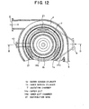
- Fig. 12 shows a sectional view of the construction of the pulp screening device of the second embodiment.
- Fig. 13 shows a sectional view taken along line B-B in Fig. 12.
- Fig. 14 shows a perspective view of the construction of the rotor of the pulp screening device of the second embodiment.
- Fig. 15 shows a sectional view of the configuration of the vane of the pulp screening device of the second embodiment.
- Fig. 16 is used for explaining the operational effect of the pulp screening device of the second embodiment.
- Fig. 17 is used to explain the operational effect of the configuration of the vane of the pulp screening device of the second embodiment. Note that the same reference numerals will be applied to the same parts as the aforementioned conventional pulp screening device or the pulp screening device of the first embodiment.
- the pulp screening device of the second embodiment has two screen cylinders 1a, 1b differing in diameter, as illustrated in Figs. 12 and 13.
- An agitation chamber 7 is formed between the screen cylinders 1a and 1b.
- An outer exit chamber 14a is formed outside the outer screen cylinder 1a, and an inner exit chamber 14b is formed inside the inner screen cylinder 1b.
- the outer exit chamber 14a is in fluid communication with the inner exit chamber 14b through the bottom portion.
- a pulp suspension flowing in a tangential direction through the entrance 2 of a cylindrical container 17, circulates through an annular flow passage 4.
- the screen cylinders 1a, 1b forming the agitation chamber 7 are provided in the peripheries thereof with a large number of slits of width 0.15 to 0.5 mm or holes of diameter 0.2 to 4.8 mm.
- a cylindrical rotor 6 is hung from the upper portion of a main shaft 11 and disposed within the agitation chamber 7.
- the rotor 6 has a plurality of vanes 21 (hereinafter referred to as distribution vanes, because the primary object of the vanes in the second embodiment is to properly distribute pulp to the inner and outer screen cylinders) at its peripheral surface, as illustrated in Fig. 14.
- the distribution vanes 21 are interconnected at their lower ends by a connecting ring 30 and are disposed at equal spaces in the circumferential direction of the rotor 6. As illustrated in Figs.
- each distribution vane 21 is located within the agitation chamber 7, holding a predetermined space (preferably 2 to 6 mm) from the inner peripheral surface of the outer screen cylinder 1a and the predetermined space from the outer peripheral surface of the inner screen cylinder 1b.
- a predetermined space preferably 2 to 6 mm
- the agitation chamber 7 is practically partitioned into a plurality of parts in the circumferential direction by the distribution vanes 21.
- the distribution vane 21 in the pulp screening device of the second embodiment is in the shape of a wedge and made up of four flat faces, namely an inner distribution wall 402, an outer distribution wall 403, an inner suction wall 406, and an outer suction wall 407, as illustrated in Fig. 15.
- An acute-angle front edge 401 is formed at a point where the inner distribution wall 402 and the outer distribution wall 403 join each other.
- an acute-angle rear edge 408 is formed at a point where the inner suction wall 406 and the outer suction wall 407 join each other.
- An obtuse-angle inner edge 404 is formed at a point where the inner distribution wall 402 and the inner suction wall 406 join each other.
- an obtuse-angle outer edge 405 is formed at a point where the outer distribution wall 403 and the outer suction wall 407 join each other.
- a distance from the inner edge 404 to the outer edge 405 i.e., the thickness of the distribution vane 21
- a distance from the front edge 401 to a line joining both the inner edge 404 and the outer edge 405 i.e., the height of the wedge with the distribution vane thickness as its base and the front edge 401 as its vertex
- the distribution vane 21 within the agitation chamber 7 is disposed so that the spacing between the inner edge 404 and the inner screen cylinder 1b, and the spacing between the outer edge 405 and the outer screen cylinder 1a, become narrowest.
- the spacing between the inner edge 404 and the inner screen cylinder 1b, and the spacing between the outer edge 405 and the outer screen cylinder 1a are each set to the aforementioned predetermined space (preferably 2 to 6 mm) .
- the position of the front edge 401 is set so that it is at the center of the agitation chamber 7 or at a position slightly offset from the center toward the outer screen cylinder 1a.
- the pulp suspension fed from an upstream pump (not shown), first flows in a tangential direction through the entrance 2 of the container 17 and circulates through the flow passage 4.
- the pulp suspension is circulating the flow passage 4, the heavy foreign objects in the pulp suspension, such as sand, etc., are discharged outside the device from a trap 5, and the remaining pulp flows into the agitation chamber 7, formed between the screen cylinders 1a, 1b inside the inner casing 3.
- the pulp within the agitation chamber 7 flows in the direction opposite to the direction of revolution of the distribution vane 21.
- the revolution flow of the pulp is distributed at the front edge 401 of the distribution vane 21 into a radially inner flow and a radially outer flow.
- the inwardly distributed pulp flows along the inner distribution wall 402 of the distribution vane 21 and is supplied to the inner screen cylinder 1b, while the outwardly distributed pulp flows along the outer distribution wall 403 and is supplied to the outer screen cylinder 1a.
- the pulp being revolved tends to flow to the side of the outer screen cylinder 1a by a difference in pressure, developed by the centrifugal force exerted on the pulp suspension.
- the distribution vane 21 is formed into the shape of a wedge having an acute-angle front edge.
- the maximum thickness of the vane 20a or 20b is "d", as illustrated in Fig. 17.
- the distance from the maximum thickness portion to the front end of the vane 20a or 20b is about 0.5 to 1.5d, and the vane front end portion is circular in shape and the radius of curvature is about 0.5d (see Fig. 17).
- the position of the front end (the foremost position with respect to the direction of flow) of the conventional vane 20a or 20b hardly changes even when the incidence angle ⁇ of the vane is adjusted (see the two-dotted line in Fig. 17).
- the conventional vane 20a or 20b is provided solely for the purpose of the agitation of pulp within the agitation chamber 7, and the blocking prevention of the screen cylinders 1a, 1b at the rear portion of the vane by negative pressure, and also because the adjustment of the incidence angle ⁇ is made for the purpose of varying the spacing between the rear portion of the vane and the screen cylinder 1a or 1b in order to adjust the magnitude of the negative pressure.
- the position of the tip end of the distribution vane 21, i.e., the position of the front edge 401 can be adjusted by adjusting the incidence angle ⁇ , since the tip end is formed into an acute-angle wedge shape, not a circular shape. Therefore, it becomes possible to equally supply pulp to the inner and outer screen cylinders 1b, 1a in accordance with a dimensional ratio of the holes 100 in the inner screen cylinder 1b and the holes 100 in the outer screen cylinder 1a.
- the internal pressure within the agitation chamber 7 gradually rises between the front edge 401 and the inner edge 404, when the revolution flow of the pulp passes through the spacing, which is gradually reduced, between the inner distribution wall 402 and the inner screen cylinder 1a.
- the internal pressure within the agitation chamber 7 gradually rises between the front edge 401 and the outer edge 405, when the revolution flow of the pulp passes through the spacing, which is gradually reduced, between the outer distribution wall 403 and the outer screen cylinder 1b.
- the revolution flow of the pulp is equally distributed at the front edge 401 to the side of the outer screen cylinder 1a and the side of the inner screen cylinder 1b in accordance with the aforementioned dimensional ratio of the holes 100.
- the pulp screening device of the second embodiment has the following advantages:
- a single distribution vane 21 is shared with the inner and outer screen cylinders 1a, 1b so that the distance between the screen cylinders can be reduced. Therefore, the speed difference of the pulp between the inner and outer screen cylinders 1a, 1b caused by the difference in diameter therebetween, and the pressure difference caused by centrifugal force, become smaller compared with conventional pulp screening device. As a result, the holes in the inner screen cylinder 1b become less liable to be clogged and a reduction in the quantity of pulp to be passed is prevented.
- the revolution flow of the pulp can be distributed into a radially inner flow and a radially outer flow by the front edge 401 of the distribution vane 21. Therefore, the pulp can be supplied equally to the outer screen cylinder 1a and the inner screen cylinder 1b independently of centrifugal force action. As a result, when the quantity of pulp to be passed is excessively reduced, clogging due to a back flow at the inner screen cylinder 1b is prevented. Also, when the quantity of pulp to be passed is increased, clogging due to an increase in passage resistance at the outer screen cylinder 1a is prevented. That is, the load required for processing the pulp can be balanced between the inner screen cylinder 1b and the outer screen cylinder 1a, and consequently, a flow-rate range for the pulp is not limited as is done in conventional pulp screening device.
- the agitation chamber 7 is practically partitioned into a plurality of parts by a plurality of distribution vanes 21, so the revolution speed of the pulp becomes approximately the same as the revolution speed of the distribution vane 21. Because of this, agitation of the pulp within the agitation chamber 7 is accelerated, and there is no possibility that a good quality of pulp will flow downward without being processed and will be discharged from the reject exit 10, and consequently, the screening efficiency rises. In addition, a rise in the revolution speed of the pulp accelerates the separation and agitation of the foreign objects and lumps of pulp at the chamfered portions of the holes 100 in the screen cylinders 1a and 1b. As a result, clogging of the holes 100 is prevented and the quantity of pulp to be passed is increased.
- the spacing between the inner suction wall 406 and the inner screen cylinder 1b, and the spacing between the outer suction wall 407 and the outer screen cylinder 1a widen gradually from the inner edge 404 and the outer edge 405, respectively. Therefore, the pressure within the agitation chamber 7 becomes negative on the rear portion side of the distribution vane 21, and the pulp suspension flows backward from the exit chambers 14a, 14b into the agitation chamber 7. As a result, lumps of pulp, etc., caught in the holes 100 of the screen cylinders 1a, 1b, are removed. Furthermore, the pulp density within the agitation chamber 7 is diluted, and repassage of high-density pulp, which is not passed through the screen cylinders 1a, 1b, becomes easy.
- the pulp screening device of the second embodiment is capable of obtaining the advantage that a large quantity of pulp to be passed can be assured with low power, by preventing clogging of the screen cylinders 1a, 1b.
- the pulp screening device of the second embodiment has also the following advantages, because the height of the wedge shape of the distribution vane 21 is set to a range of 2 to 5 times the base of the wedge (i.e., when a distance from the inner edge 404 to the outer edge 405 is taken to be "d," a distance from the front edge 404 to a line joining both the inner edge 404 and the outer edge 405 is set to 2 to 5d).
- the height of the wedge shape of the distribution vane 21 exceeds five times the base of the wedge shape, the friction resistance of the distribution vane 21 will increase and therefore the operating power per unit processing ability will rise.
- a plurality of distribution vanes 21 are disposed, but if the height of the wedge shape becomes higher (i.e., if the vane width becomes wider), adjacent distribution vanes 21 will become too close. As a result, there is also a possibility that proper distribution of the pulp cannot be performed.
- the height of the wedge shape of the distribution vane 21 be set to a range of two to five times the base of the wedge shape. Since the pulp screening device of the second embodiment is correctly set to the aforementioned range, there is no reduction in the screening efficiency and no rise in the operating power per unit processing ability. Therefore, it becomes possible to prevent clogging of the screen cylinders 1a, 1b and assure a large quantity of pulp to be passed with low power.
- the cross section taken in the direction perpendicular to the axis, is not a curved surface formed in a fixed curvature and requires straightness in the axial direction. Because of this, there is a problem that the manufacturing cost will be increased.
- the distribution vane 21 in the pulp screening device of the second embodiment is formed with four flat faces, an inner distribution wall 402, an outer distribution wall 403, an inner suction wall 406, and an outer suction wall 407. Therefore, there is also an advantage that machining is easy and manufacturing costs can be reduced.
- the distribution vane 21 in the pulp screening device of the second embodiment is not limited to the configuration shown in Fig. 15.
- the radial depth, circumferential width, axial length, axial inclination, number of vanes, configuration of the inner distribution wall, outer distribution wall, inner suction wall, and outer suction wall, etc. can be varied according to pulp type, pulp density, screen cylinder hole dimensions, rotor speed, etc., without departing from the scope of the invention hereinafter claimed.
- the configuration of the distribution vane 21 will be satisfied, if it is formed from at least four wall faces, an inner distribution wall, an outer distribution wall, an inner suction wall, and an outer suction wall and is in the form of an acute-angle wedge in the tip end direction, and if, when it is assumed that a distance from the inner edge to the outer edge is "d," a distance from the front edge to a line joining both the inner edge and the outer edge is set to 2 to 5d.
- an outer distribution wall 403 and an outer suction wall 407 may be formed into convex faces, and an inner distribution wall 402 and an inner suction wall 406 may be formed into concave faces.
- an inner distribution wall 402 and an outer distribution wall 403 may be formed into flat faces, and an outer distribution wall 407 and an inner suction wall 406 may be formed into convex and concave faces, respectively.
- the front and rear edges 401, 408 in the distribution vanes 21 of Figs. 15, 18, and 19 may be rounded.
- the thickness d of the distribution vane 21 it is possible to make the thickness d of the distribution vane 21 constant, since the spacing between the inner screen cylinder 1b and the outer screen cylinder 1a can be made constant within the operational range of the device independently of cylinder diameter. In the case where a small-diameter screen cylinder with a large curvature is employed, however, there are cases where the height of the wedge shape of the distribution vane 21 is limited to less than 5d (i.e., less than five times vane thickness).
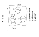
- Fig. 23 shows a plan view of the construction of the screen cylinder of the third embodiment.
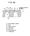
- Fig. 24 shows a sectional view taken along line C-C in Fig. 23. Note that the same reference numerals will be applied to the same parts as the aforementioned embodiments.
- the pulp screening device of the third embodiment is characterized only in screen cylinder construction, particularly hole configuration, and the remaining construction is the same as the conventional pulp screening device (refer to Figs. 28 and 29, or Figs. 34 and 35).
- the screen cylinder construction will preponderantly be described, and a description of the remaining construction is omitted. Note that in the third embodiment, a description will be made in the case where the specific hole configuration is applied to the outer screen cylinder 1a of a double screen cylinder.
- conical hollows 51 are bored zigzag in the surface of the screen cylinder 1a, as illustrated in Figs. 23 and 24.
- a hole (round hole) 50 is provided to be offset on the upstream side of revolution flow (i.e., in the direction opposite to the advancing direction of the vane) from the center of the corresponding conical hollow 51.
- the front edge 52 (positioned on the upstream side of the revolution flow) of the round hole 50 is positioned outside the outer peripheral circle of the conical hollow 51, and the rear edge 53 (positioned on the downstream side of the revolution flow) is positioned inside the outer peripheral circle of the conical hollow 51.
- the front edge 52 is formed substantially perpendicular to the surface of the screen cylinder 1a, while the rear edge 53 has an obtuse angle and constitutes the inlet of the conical hollow 51 along with the inclined face of the conical hollow 51.
- the round hole 50 is bored toward an exit chamber 14a (see Fig. 13) and forms an axial wall 55, and is joined with an enlarged passage 56 widening toward the exit chamber 14a.
- the front edge 52 of the round hole 50 is formed substantially perpendicular to the surface of the screen cylinder 1a. Therefore, when the revolution flow of pulp takes place, a strong, turbulence S develops at the inlet of the round hole 50, and the pulp is satisfactorily agitated. Since the rear edge 53 is formed to have an obtuse angle, a lump of pulp and foreign objects are prevented from being caught in the rear edge 53. Furthermore, the turbulence S is near the front edge 52, so foreign objects are easily removed and clogging of the round hole 50 is prevented. Therefore, there is an advantage that clogging can be prevented even when vanes are revolved at relatively low speeds and that a large quantity of pulp can thus be screened and processed with low power.
- the center of the round hole 50 is offset from the center of the conical hollow 51 in the direction opposite to the direction of the revolution flow, whereby the front edge 52 for developing the turbulence S is also used as the hole inlet and the dimension of the inclined portion 54 is assured. Therefore, the zigzag pitch can be reduced and there is also an advantage that the number of round holes 50 per unit area can be increased and that the quantity of pulp to be passed is thus increased.
- the conical hollow 51 can be formed into the required configuration with a minimum amount of machining (e.g., mechanical machining such as drilling, etc., or electron beam machining such as laser machining, etc.). Therefore, the conical hollow 51 is advantageous in mechanical strength and there is also advantage that a thin flat plate can be employed in the screen cylinder 1a.
- machining e.g., mechanical machining such as drilling, etc., or electron beam machining such as laser machining, etc.
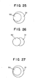
- the construction of the screen cylinder 1a of the pulp screening device of the third embodiment is not limited to the one illustrated in Figs. 23 and 24, but will be satisfied if at least the front edge 52 of the round hole 50 is formed substantially perpendicular to the screen cylinder surface, and if the rear edge 53 has an obtuse angle and constitutes the hole inlet along with the inclined portion 54 of the conical hollow 51. Therefore, as illustrated in Fig. 25, the outer peripheral circle of the conical hollow 51 may coincide with the front edge 52 of the round hole 50. As illustrated in Fig. 26, the diameter of the outer peripheral circle of the conical hollow 51 may coincide with the diameter of the round hole 50, and the rear edge 53 of the round hole 50 may be disposed at the center of the conical hollow 51.
- the round hole 50 is disposed within the outer peripheral circle of the conical hollow 51.
- the front edge 52 of the round hole 50 is formed substantially perpendicular to the screen cylinder surface, and the center position of the round hole 50 is offset on the upstream side of the revolution flow.
- the construction of the screen cylinder in the pulp screening device is not limited to devices provided with two screen cylinders, as in the third embodiment. For instance, it is also applicable to devices having a single screen cylinder outside or inside an agitation chamber, as illustrated in Fig. 28.
- the present invention has been described by way of a preferred embodiment thereof, the invention is not limited to the embodiment.
- the common vanes in the first embodiment of the invention may be combined with the screen cylinders of the third embodiment.
- the distribution vanes in the second embodiment may be combined with the screen cylinders of the third embodiment.
Description
- The present invention relates to a pulp screening device for separating good-quality fibers and foreign objects in paper pulp.
- U.S. Patent No. 5,009,774 discloses in combination the technical features of the pre-characterizing part of claim 1 below.
- On the upstream side of a paper machine, there is provided a pulp screening device (pulp screen). The pulp screening device is a device for screening and separating good-quality fibers and foreign objects in paper pulp (i.e., a pulp suspension with a pulp density of 0.2 to 5 %) with a screen cylinder thereof. Typically, the pulp screening device is equipped with one or two screen cylinders. First, the construction of a pulp screening device with a single screen cylinder will be described with reference to Figs. 28 and 29. Fig. 28 shows a part-sectional plan view of a conventional pulp screening device. Fig. 29 shows a part-sectional side view taken in the direction of arrow D of Fig. 28.
- A pulp suspension is fed to the pulp screening device by a pump. As illustrated in Figs. 28 and 29, the pulp suspension flows in a tangential direction through the
entrance 2 of acylindrical container 17, and advances in anannular flow passage 4, formed by aninner casing 3 and the inner wall of thecontainer 17. When the pulp suspension is circulating through theannular flow passage 4, heavy foreign objects such as sand, etc., are discharged outside the device from atrap 5 provided in the tangential direction opposite to theentrance 2, and the remaining pulp flows inside theinner casing 3 through theflow passage 4. Note that acover 19 is provided on the upper surface of thecontainer 17 so that the device can be operated under pressure. - A cylindrical screen cylinder 1 is disposed inside the
inner casing 3. The upper portion of the screen cylinder 1 is fixedly attached to theinner casing 3, and this screen cylinder 1 partitions the inner side of theinner casing 3 into anagitation chamber 7 and anexit chamber 14. The pulp flowing in theflow passage 4 first flows in theannular agitation chamber 7 formed inside the screen cylinder 1. - A large number of slits of width 0.15 to 0.5 mm or holes of diameter 0.2 to 4.8 mm are provided in the peripheral surface of the screen cylinder 1, and the pulp is filtered and sorted by these slits or holes when flowing downward along the
agitation chamber 7. That is, the good-quality fibers that can pass through the slits or holes in the peripheral surface of the screen cylinder 1 are discharged from anexit 9 via theexit chamber 14, while the foreign objects of sizes that cannot pass through the slits or holes in the screen cylinder, as they are, flow downward along theagitation chamber 7 and are discharged from areject exit 10. - In addition, a
rotor 6 is disposed within theagitation chamber 7. Therotor 6 is hung from the upper portion of amain shaft 11 and is equipped with a plurality ofvanes 20 at equal spaces in the circumferential direction. Thevane 20 is positioned, holing a predetermined space (2.5 to 8 mm) from the inner peripheral surface of the screen cylinder 1. Themain shaft 11 is supported by bearings so that it is free to rotate, and is driven to rotate by anelectric motor 13 through a V-pulley (not shown) mounted on the lower end portion thereof. If therotor 13 rotates and therefore thevanes 20 revolve within theannular agitation chamber 7, the pulp suspension within theagitation chamber 7 is agitated. The foreign objects in the pulp are separated, and tangled fibers are untangled. As a result, clogging of the slits or holes in the screen cylinder 1 is prevented. - Fig. 30 shows how clogging of the slits or holes in the screen cylinder 1 is prevented by the
vanes 20. As illustrated in Fig. 30A, thevane 20 revolves along the surface of the screen cylinder 1 at high speeds (10 to 30 m/s), holding a constant space from the cylinder surface. When thevalve 20 is revolving, negative pressure is developed between thevane 20 and the screen cylinder 1, as shown in Fig. 30B. The suction force, developed by this negative pressure, causes the solution to flow backward into theagitation chamber 7 and therefore the tangled fibers or foreign objects, blockingholes 100 in the surface of the screen cylinder 1, are removed. After passage of thevane 20, the pulp suspension will flow from theagitation chamber 7 into theexit chamber 14 again, and theholes 100 in the screen cylinder 1 will be clogged with tangled fibers and foreign objects. However, the tangled fibers, etc., newly blocking theholes 100, are removed by the negative pressure produced by passage of thenext vane 20. In the conventional pulp screening device, clogging of the holes in the screen cylinder 1 is prevented by repeating the aforementioned operation. - Fig. 31 shows a sectional view of the configuration of the
hole 100 in the screen cylinder 1. Thehole 100 is circular in shape, and achamfered face 101 in the form of a dish is formed coaxially at the inlet of the hole 100 (on the side of the agitation chamber 7) . When thevane 20 passes over thechamfered surface 101 in the surface of the screen cylinder 1, a turbulence (separating vortex) develops at the inlet of thehole 100, as shown by an arrow S in Fig. 31, and clogging of thehole 100 is suppressed by the turbulence S. - Furthermore, there are screen plates 1 of cross sections such as those shown in Figs. 32 and 33. In the case of Fig. 32,
trapezoidal grooves 111 are formed in the axial direction of the screen plate 1 (perpendicular to the paper surface) and forms a plurality ofholes 110 at the bottoms of the grooves 33. In the case of Fig. 33, an axial waveform is formed on the peripheral surface of the screen cylinder 1, and a plurality ofholes 120 are bored axially in theinclined portion 121 of the waveform. In any of the cross sections shown in Figs. 32 and 33, revolution flow caused by thevane 20 develops a turbulence S at the inlet of the hole, thereby preventing clogging of the hole. - Now, the construction of a pulp screening device with a double screen cylinder (inner and outer screen cylinders) will be described with reference to Figs. 34 and 35. Fig. 34 shows a sectional view of the conventional pulp screening device with two inner and outer screen cylinders, and Fig. 35 shows a sectional view taken substantially along line E-E in Fig 34. Note that the same reference numerals will be applied to the same parts as the aforementioned conventional pulp screening device having a single screen cylinder.
- As illustrated in Figs. 34 and 35, a pulp suspension flows in a tangential direction through the
entrance 2 of acylindrical container 17 and circulates through anannular flow passage 4. When the pulp suspension is circulating through theannular flow passage 4, heavy foreign objects such as sand, etc., are discharged outside the device from atrap 5 provided in the tangential direction of theflow passage 4, and the remaining pulp suspension flows from theflow passage 4 to inside aninner casing 3. -
Cylindrical screen cylinders inner casing 3. Thesescreen cylinders inner casing 3 into anagitation chamber 7 andexit chambers flow passage 4 first flows in theannular agitation chamber 7, formed between thescreen cylinders agitation chamber 7, part of the pulp passes through theinner screen cylinder 1b and is filtered and sorted in theinner exit chamber 14a. The remaining pulp passes through the outer screen cylinder 1, and is filtered and sorted in theouter exit chamber 14. On the other hand, the foreign objects of sizes that cannot pass through thescreen cylinders agitation chamber 7 and are discharged from areject exit 10. - In addition, within the
agitation chamber 7, a plurality ofouter vanes 20a are disposed in opposition to theouter screen cylinder 1a and a plurality ofinner vanes 20b are disposed in opposition to theinner screen cylinder 1b. Thevanes rotor 6 hung from the upper portion of amain shaft 11. Theouter vanes 20a are disposed at equal spaces in the circumferential direction, holding a constant space (2.5 to 8 mm) from theouter screen cylinder 1a. Similarly, theinner vanes 20b are disposed at equal spaces in the circumferential direction, holing the constant space (2.5 to 8 mm) from theinner screen cylinder 1b. Themain shaft 11 is freely rotatably supported by bearings and is driven to rotate by an electric motor (not shown) through a V-pulley 18 mounted on the lower end portion thereof. If therotor 13 rotates and therefore thevanes annular agitation chamber 7, the pulp suspension within theagitation chamber 7 is agitated. The foreign objects in the pulp are separated, and tangled fibers are untangled. As a result, clogging of the slits or holes in thescreen cylinders - The aforementioned pulp screening devices, however, have the following problems:
- First, the conventional pulp screening device shown in Figs. 28 and 29 has a limit to its processing ability since it has only a single screen cylinder 1. In addition, because of the configuration of the
conventional vane 20, the revolution flow caused by thevane 20 becomes faster as it is near the surface of thevane 20 and slower as it is away from the vane surface. Therefore, the efficiency of cleaning the surface of the screen cylinder 1 is low, and there is a problem that the passage amount of the pulp will be reduced. Furthermore, the surface of thevane 20 remote from the surface of the screen cylinder 1 wastefully consumes the power required for friction, because it makes no contribution to the cleaning of the surface of the screen cylinder 1. - In the conventional pulp screening device shown in Figs. 34 and 35, the speed of the revolution flow, developed by revolution of the
vanes inner screen cylinder 1b than at theouter screen cylinder 1a because of the difference in diameter between the inner andouter screen cylinders inner screen cylinder 1b is lower than that acting on theouter screen cylinder 1a because of a difference in centrifugal force. Therefore, theouter screen cylinder 1a tends to pass the pulp to more than the effective area of thescreen cylinder 1a, whereas theinner screen cylinder 1b tends to pass the pulp to less than the effective area of thescreen cylinder 1b. - Because of this, when the quantity of pulp to be processed is excessively reduced, the
outer screen cylinder 1a will pass the pulp therethrough, but there is a problem that theinner screen cylinder 1b will be liable to be clogged due to pulp flowing backward. Conversely, when the quantity of pulp to be processed is increased, theinner screen cylinder 1b will properly pass pulp therethrough, but there is a problem that theouter screen cylinder 1a will increase in passage resistance and will be likely to be clogged. - In addition, because revolution flow passes through between the inner and
outer vanes agitation chamber 7 becomes faster only in the vicinities of the inner andouter vanes outer vanes screen cylinders reject exit 10 without being processed by thescreen cylinders - In addition, as described above, the conventional pulp screening device has the problem that the quantity of pulp to be passed will be limited by clogging of the holes in the screen cylinder 1. The clogging of the holes in the screen cylinder 1 results from the configuration of the holes formed in the screen cylinder 1.
- More specifically, the turbulence S (see Figs. 31 to 33), developed at the inlet of the hole by the revolution flow resulting from revolution of the
vane 20, has the effect of preventing the hole from being clogged. However, the strength of the turbulence S is affected by the configuration of the front edge of the hole (located on the upstream side of the revolution flow) . In addition, the difficulty for tangled fibers to be caught, and the ease of removing foreign objects, are affected by the configuration of the rear edge of the hole (located on the downstream side of the revolution flow). - In the case of configuration such as that shown in Fig. 31, the turbulence S develops at the inclined surface, on the upstream side, of the
hole 100 formed by the dish-shaped chamberedsurface 101, but the developed vertex S is weak because the inclined surface is gentle. Therefore, the turbulence S is less liable to reach thefront edge 102 orrear edge 103 of thehole 100. Because of this, the effect of preventing clogging by the turbulence S is low. In addition, because the dish-shaped chamberedsurface 101 is formed coaxially with thehole 100, room for forming the dish-shaped chambered surface is required and the number of holes per unit area is thus limited. Because of this, there is a limit to increasing the quantity of pulp to be passed, by increasing the number ofholes 100. - In addition, in the case of configuration such as the one shown in Fig. 32, the turbulence S which develops is strong, because the vertical portion of the
trapezoidal groove 111 is located on the upstream side of flow. However, since thefront edge 112 of thehole 110 is positioned at the groove bottom portion near the vertical portion of thetrapezoidal groove 111, the vortex S developed is less likely to reach thefront edge 112 and therefore the effect of preventing clogging of thehole 110 is low. Similarly, as therear edge 113 is positioned at the groove bottom portion and is away from theinclined portion 114, separation of tangled fibers, etc, caught in thehole 100, is not easy. Besides, because thehole 110 can be disposed only in the bottom portion of thetrapezoidal groove 111, the number of holes per unit area is also limited. - Furthermore, in the case of configuration such as that shown in Fig. 33, the turbulence S develops at the vertex of the waveform formed on the surface of the screen cylinder 1. However, the
front edge 122 of thehole 120 is far from the vertex of the waveform and the front andrear edges inclined portion 121 of the waveform. Therefore, the turbulence S is less likely to reach theedges rear edge 123 has an acute angle, separation of a lump of pulp, etc., caught on the edge, is not easy. Moreover, the number of holes per unit area is limited, because thehole 120 can be disposed only in theinclined portion 121 of the waveform. - As described above, in any of the hole configurations shown in Figs. 31 to 33, the effect of preventing clogging by the turbulence S is not satisfactory. Therefore, it is necessary to make the turbulence S stronger by revolving the
vanes 20 at high speeds in order to prevent clogging of holes. The power required for revolving thevanes 20, however, becomes greater in proportion to the square to cube of the revolution speed, so the quantity of passage per consumption power is inversely reduced. - In U.S. Patent No. 2,975,899 a screening device is disclosed which comprises inner and outer cylindrical screens, at least two vanes of streamlined cross-sectional configuration extending into the space between the screens, and a pair of annular chambers, one disposed outside of the outer screen and one disposed within the inner screen. The device further comprises means for withdrawing screened suspension from the chambers, and means for withdrawing rejected material from the space between the screens.
- U.S. Patent No. 5,497,886 discloses a screening apparatus for papermaking pulp, the apparatus comprising a screening chamber defined between a stationary screen member and a rotor, an accepts chamber outboard of the screening chamber, as well as a plurality of half-foil members disposed on the outer surface of the rotor. A rejects discharge is provided downstream of the screening chamber, and an accepts discharge is provided in the accepts chamber.
- The present invention, which is defined in claim 1 below, has been made in view of the problems found in the prior art. Accordingly, it is the primary object of the present invention to provide a pulp screening device that power, by preventing clogging of a screen cylinder.
- To achieve this end and in accordance with one important aspect of the present invention, there is provided a pulp screening device, comprising:
- a pair of inner and outer screen cylinders; and
- one or a plurality of vanes which revolve within an agitation chamber formed between the inner and outer screen cylinders, holding a predetermined small space from each of the inner and outer screen cylinders.
- In addition, the cross section of an inner discharge tube at a point where the inner discharge tube joins an outer discharge tube is set greater than the cross section of the outer discharge tube, pulp being passed through the inner screen cylinder and flowing in the inner discharge tube and also being passed through the outer screen cylinder and flowing in the outer discharge tube.
- The agitation chamber can be practically partitioned in the circumferential direction, by providing the vanes which revolve within the agitation chamber formed between the inner and outer screen cylinders, holding a predetermined small space from each of the inner and outer screen cylinders. With this arrangement, the internal pressure within the agitation chamber becomes higher, as the revolution speed of pulp is increased. Therefore, the separation and agitation of foreign objects and lumps of pulp are accelerated, and clogging of the screen cylinders is prevented and the quantity of pulp to be passed is increased. In addition, the distance between the inner and outer screen cylinders can be shortened by sharing a single vane with the inner and outer screen cylinders. Because of this, the speed difference of the pulp between the inner and outer screen cylinders caused by the difference in diameter therebetween, and the pressure difference caused by centrifugal force, become smaller compared with prior art. Particularly, a reduction in the quantity of pulp to be passed due to clogging of the inner screen cylinder is prevented. Therefore, there is no possibility that the screen cylinders will be clogged even when the revolution speed of the vanes is relatively slow, and there is obtained an effect that a large quantity of pulp can be screened with low power.
- Furthermore, with this setting, an effect is obtainable that the flow of the pulp from the inner discharge tube becomes satisfactory and that the quantity of pulp to be processed is thus increased.
- In a first preferred form of the present invention, the revolution-direction front portion of the vane has a wall face extending radially toward the peripheral surfaces of the inner and outer screen cylinders. With this arrangement, the direction of the revolution flow of the pulp is changed from the circumferential direction to the radial direction by the wall face. The radial flow of the pulp renders it possible to partition the agitation chamber efficiently.
- In a second preferred form of the present invention, the wall face is formed at a right or acute angle to the direction of revolution. With this arrangement, the revolution flow of the pulp can perpendicularly approach the peripheral surfaces of the inner and outer screen cylinders, and it becomes possible to partition the agitation chamber more efficiently.
- In a third preferred form of the present invention, the cross section of the vane is formed so that the spacing between the cross section and each of the inner and outer screen cylinders widens gradually from the wall face in the direction of revolution. With this configuration, the pressure within the agitation chamber becomes negative on the rear portion side of the vane. Therefore, the pulp suspension flows backward from outside the inner and outer screen cylinders into the agitation chamber. As a result, lumps of pulp, etc., caught in the screen cylinders, are removed. In addition, the pulp density within the agitation chamber is diluted, and there is obtained an effect that repassage of the high-density pulp, which is not passed through the screen cylinders, becomes easy.
- In a fourth preferred form of the present invention, the cross section of the vane is formed into the shape of a wedge extending at an acute angle from a revolution-direction tip end to both proximity portions closest to the inner and outer screen cylinders. With this shape, the position of the tip end of the vane can be adjusted by adjusting the incidence angle of the vane, and it becomes possible to supply pulp to the inner and outer screen cylinder equally.
- In a fifth preferred form of the present invention, a distance from the tip end to both proximity portions is set to two to five times a distance between both proximity portions. With this, there is no reduction in the screening efficiency of the screen cylinder and no rise in the operating power per unit processing ability of the screen cylinder. Therefore, clogging of the inner and outer screen cylinders is prevented, whereby it becomes possible to assure a large quantity of pulp to be passed with low power.
- In a sixth preferred form of the present invention, the aforementioned tip end is disposed at a center between the inner and outer screen cylinders, or at a position offset from the center toward the outer screen cylinder. With this arrangement, the load for processing pulp can be balanced between the inner and outer screen cylinders.
- In a seventh preferred form of the present invention, the cross section of the vane is formed so that the spacing between the cross section and each of the inner and outer screen cylinders widens gradually from both proximity portions in the direction of revolution. With this configuration, the pressure within the agitation chamber becomes negative on the rear portion side of the vane. Therefore, the pulp suspension flows backward from outside the inner and outer screen cylinders into the agitation chamber. As a result, lumps of pulp, etc., caught in the screen cylinders, are removed. In addition, the pulp density within the agitation chamber is diluted, and there is obtained an effect that repassage of the high-density pulp, which is not passed through the screen cylinders, becomes easy.
- In an eighth preferred form of the present invention, adjacent vanes of the aforementioned plurality of vanes are connected by a partition wall. This further divides the agitation chamber into two parts. Therefore, flow from inside the agitation chamber to outside the agitation chamber, which is caused by centrifugal force, can be blocked, and it becomes possible to increase the quantity of pulp to be passed at the inner screen cylinder. A pulp screening device may comprise:
- a screen cylinder; and
- one or a plurality of vanes which revolve within an agitation chamber formed outside or inside the screen cylinder, holding a predetermined small space from the screen cylinder;
- wherein a revolution-direction front portion of the vane has a wall face extending radially toward the peripheral surface of the screen cylinder, and the vane is formed so that the spacing between the vane and the screen cylinder widens gradually from the wall face toward a revolution-direction rear end.
- With such a construction, clogging of the screen cylinder may be prevented by making the difference in pressure within the agitation chamber greater before and after the wall face, and there may be obtained an effect that a great quantity of pulp can be screened with low power. Another pulp screening device may comprise:
- a screen cylinder having a plurality of filter holes; and
- one or a plurality of vanes which revolve within an agitation chamber formed outside or inside the screen cylinder, holding a predetermined small space from the screen cylinder;
- wherein a plurality of conical hollows are provided in the peripheral surface of the screen cylinder which faces the agitation chamber, and the filter hole is formed to be offset from the center of the conical hollow in the direction opposite to the direction in which the vane revolves.
- With construction like this, a strong, turbulence may be developed at the inlet of the filter hole by the revolution flow of the pulp, and the pulp may be satisfactorily agitated. In addition, a lump of pulp and foreign objects are prevented from being caught in the filter holes, and clogging of the filter holes may be prevented. Therefore, there may be obtainable an effect that a large quantity of pulp can be screened with low power.
-
- FIG. 1 is a part-sectional plan view showing a pulp screening device constructed according to a first embodiment of the present invention;
- FIG. 2 is a part-sectional side view taken in the direction of arrow A of FIG. 1;
- FIG. 3 is a perspective view showing the construction of the rotor of the pulp screening device of the first embodiment of the present invention;
- FIG. 4 is a sectional view showing the configuration of the vane of the pulp screening device of the first embodiment of the present invention;
- FIG. 5A is a diagram for explaining the operational effect of the pulp screening device of the first embodiment, the positional relationship between the inner and outer screen cylinders and the vane being shown;
- FIG. 5B is a diagram showing a pressure distribution that acts on the screen cylinders in the positional relationship shown in FIG. 5A;
- FIG. 6 is a sectional view showing a first variation of the vane of the pulp screening device of the first embodiment of the present invention;
- FIG. 7 is a sectional view showing a second variation of the vane of the pulp screening device of the first embodiment of the present invention;
- FIG. 8 is a sectional view showing a third variation of the vane of the pulp screening device of the first embodiment of the present invention;
- FIG. 9 is a perspective view showing a variation of the rotor of the pulp screening device of the first embodiment of the present invention;
- FIG. 10 is a sectional view showing a fourth variation of the vane of the pulp screening device of the first embodiment of the present invention, the positional relationship between the inner and outer screen cylinders and the vane being shown;
- FIG. 11 is a perspective view showing the construction of a rotor that corresponds to the configuration of the common vane shown in FIG. 10;
- FIG. 12 is a sectional plan view showing a pulp screening device constructed according to a second embodiment;
- FIG. 13 is a sectional view taken substantially taken along line B-B in FIG. 12;
- FIG. 14 is a perspective view showing the construction of the rotor of the pulp screening device of the second embodiment;
- FIG. 15 is a sectional view showing the configuration of the vane of the pulp screening device of the second embodiment;
- FIG. 16A is a diagram for explaining the operational effect of the pulp screening device of the second embodiment, the positional relationship between the inner and outer screen cylinders and the vane being shown;
- FIG. 16B is a diagram showing a pressure distribution that acts on the outer screen cylinder in the positional relationship shown in FIG. 16A;
- FIG. 16C is a diagram showing a pressure distribution that acts on the inner screen cylinder in the positional relationship shown in FIG. 16A;
- FIG. 17 is a diagram for explaining the operational effect of the pulp screening device of the second embodiment, the configuration of a conventional vane which becomes an object of comparison having been shown;
- FIG. 18 is a sectional view showing a first variation of the vane of the pulp screening device of the second embodiment;
- FIG. 19 is a sectional view showing a second variation of the vane of the pulp screening device of the second embodiment;
- FIG. 20 is a sectional view showing a third variation of the vane of the pulp screening device of the second embodiment;
- FIG. 21 is a sectional view showing a fourth variation of the vane of the pulp screening device of the second embodiment;
- FIG. 22 is a sectional view showing a fifth variation of the vane of the pulp screening device of the second embodiment;
- FIG. 23 is a plan view showing the construction the screen cylinder of a pulp screening device constructed according to a third embodiment;
- FIG. 24 is a sectional view taken substantially taken along line C-C in FIG. 23;
- FIG. 25 is a diagram showing a first variation of the positional relationship between the conical hollow and round hole of the pulp screening device constructed of the third embodiment;
- FIG. 26 is a diagram showing a second variation of the positional relationship between the conical hollow and round hole of the pulp screening device of the third embodiment;
- FIG. 27 is a diagram showing a third variation of the positional relationship between the conical hollow and round hole of the pulp screening device of the third embodiment;
- FIG. 28 is a part-sectional plan view showing a conventional pulp screening device;
- FIG. 29 is a part-sectional side view taken in the direction of arrow D of FIG. 28;
- FIG. 30A is a diagram for explaining the operational effect of the conventional pulp screening device, the positional relationship between the screen cylinder and the vane being shown;
- FIG. 30B is a diagram showing a pressure distribution that acts on the screen cylinder in the positional relationship shown in FIG. 30A;
- FIG. 31 is a sectional view showing the configuration of the hole in the screen cylinder of the conventional pulp screening device;
- FIG. 32 is a sectional view showing a first variation of the hole in the screen cylinder of the conventional pulp screening device;
- FIG. 33 is a sectional view showing a second variation of the hole in the screen cylinder of the conventional pulp screening device;
- FIG. 34 is a sectional view showing another conventional pulp screening device; and
- FIG. 35 is a sectional view taken substantially along line E-E in FIG. 34.
- A preferred embodiment of the present invention will hereinafter be described with reference to the drawings.
- Figs. 1 through 5 show a pulp screening device constructed according to a first embodiment of the present invention. The pulp screening device will hereinafter be described with reference to Figs. 1 to 5. Fig. 1 shows a part-sectional plan view of the construction of the pulp screening device. Fig. 2 shows a part-sectional side view taken in the direction of arrow A of Fig. 1. Fig. 3 shows a perspective view of the construction of the rotor of the pulp screening device. Fig. 4 shows a sectional view of the configuration of the common vane of the pulp screening device of the first embodiment. Fig. 5 shows a diagram for explaining the operational effect of the pulp screening device. Note that the same reference numerals will be applied to the same parts as the aforementioned conventional pulp screening device.
- The pulp screening device has two
screen cylinders agitation chamber 7 is formed between thescreen cylinders outer exit chamber 14a is formed outside theouter screen cylinder 1a, and aninner exit chamber 14b is formed inside theinner screen cylinder 1b. - A pulp suspension, fed from a pump (not shown), first flows in a tangential direction through the
entrance 2 of acylindrical container 17 and circulates through anannular flow passage 4, formed by aninner casing 3 and the inner wall of thecontainer 17. When the pulp suspension is circulating through theflow passage 4, heavy foreign objects such as sand, etc., are discharged outside the device from atrap 5 provided in the tangential direction opposite from theentrance 2. The remaining pulp flows from theflow passage 4 into theagitation chamber 7. - The
screen cylinders agitation chamber 7, part of the pulp passes through theinner screen cylinder 1b and is filtered and sorted in theinner exit chamber 14b, while the remaining pulp passes through theouter screen cylinder 1a and is filtered and sorted in theouter exit chamber 14a. On the other hand, the foreign objects of sizes that cannot pass through thescreen cylinders agitation chamber 7 and are discharged from areject exit 10 via areject receiver 25. - In the pulp screening device, the
inner exit chamber 14b and theouter exit chamber 14a are completely partitioned, and the pulp suspension, sorted in the outer exitedchamber 14a from theagitation chamber 7, passes through anouter discharge tube 16 and is discharged from theexit 9. On the other hand, the pulp suspension sorted in theinner exit chamber 14b passes through aninner discharge tube 15 provided in theouter discharge tube 16, and is discharged from theexit 9, joining the pulp suspension flowing from theouter exit chamber 14a into thedischarge 16. Note that the dimension of the cross section of the exit of theinner discharge tube 15 is set equal to or greater than the dimension of the cross section of theouter discharge tube 16 at a point where theouter discharge tube 16 joins theinner discharge tube 15. Also, the bottom surface of theinner exit chamber 14b, the bottom surface of theouter exit chamber 14a, and the bottom surface of thereject receiver 25 are inclined downward toward theexits - A
cylindrical rotor 6 is hung from the upper portion of amain shaft 11 and disposed within theagitation chamber 7. Therotor 6 has a plurality of vanes 12 (hereinafter referred to as common vanes, because each vane in the first embodiment acts in common on the inner and outer screen cylinders) at its peripheral surface, as illustrated in Fig. 3. Thecommon vanes 12 are interconnected at their lower ends by a connectingring 30 and are disposed at equal spaces in the circumferential direction of therotor 6. As illustrated in Figs. 1 and 2, eachcommon vane 12 is located within theagitation chamber 7, holding a predetermined space (preferably 2 to 6 mm) from the inner peripheral surface of theouter screen cylinder 1a and the predetermined space from the outer peripheral surface of theinner screen cylinder 1b. With this arrangement, theagitation chamber 7 in the pulp screening device of the first embodiment is practically partitioned in the circumferential direction by thecommon vanes 12. - Now, the configuration of the
common vane 12 will be described. Thecommon vane 12 in the pulp screening device of the first embodiment has afront wall 201 and adeflection wall 202, as illustrated in Fig. 4. Thefront wall 201 extends from atip end 205 in the direction opposite to the direction of revolution, and thedeflection wall 202 is continuous to thefront wall 201 and extends in the radial direction of the rotor 6 (perpendicular to the direction of revolution). Thedeflection wall 202 is jointed to a pair of rearcurved faces 204 extending from arear end 206 in the direction of revolution, and the joined portion forms an acute-angle edge 203. - With the aforementioned vane configuration, the spacing, within the
agitation chamber 7, between thecommon vane 12 and thescreen cylinder tip end 205 toward the rear direction and then becomes even narrower suddenly at thedeflection wall 202 and narrowest at theedge 203. In the pulp screening device of the first embodiment, the spacing between theedge 203 and thescreen cylinder edge 203 to a rear end 206 (refer to Fig. 5A). Note that it is preferable that thedeflection wall 202 be concave and also preferable that the angle of deflection at the deflection wall 202 (which is an angle, indicated by θ in Fig. 5A, which is formed by both the direction of revolution and the direction in which thedeflection wall 202 extends) be 90 degrees or less. - Now, a description will be made of the operation of the pulp screening device of the first embodiment constructed as described above.
- The pulp suspension, fed from an upstream pump (not shown), first flows in a tangential direction through the
entrance 2 of thecontainer 17 and circulates through theflow passage 4. When the pulp suspension is circulating theflow passage 4, the heavy foreign objects in the pulp suspension, such as sand, etc., are discharged outside the device from thetrap 5 provided in the tangential direction opposite to theentrance 2, and the remaining pulp flows into theagitation chamber 7, formed between thescreen cylinders inner casing 3. - If the
common vane 12 revolves within and along theannular agitation chamber 7, as shown in Fig. 5A, the pulp within theagitation chamber 7 flows in the direction opposite to the direction of revolution of thecommon vane 12, relative to thecommon vane 12. However, because thecommon vane 12 is provided with thedeflection wall 202 extending in the radial direction, the circumferential flow of the pulp strikes on thedeflection wall 202 and is therefore changed to the radial flow. As a result, the flow of the pulp into the space between thescreen cylinder common vane 12 is suppressed. That is, theagitation chamber 7 is practically partitioned at the space between thescreen cylinder common vane 12, by the radial flow near thedeflection wall 202. - Thus, the
agitation chamber 7 is practically partitioned into a plurality of parts in the circumferential direction by the radial flow of the pulp near thedeflection walls 202. Therefore, the pulp, within theagitation chamber 7 partitioned into a plurality of parts, is pushed by thecommon vanes 12 and revolved in the circumferential direction at approximately the same speed as that of thecommon vane 12. Since the radial flow of the pulp toward the surface of thescreen cylinder deflection wall 202, the internal pressure within theagitation chamber 7 rises greatly from thetip end 205 to theedge 203, as illustrated in Fig. 5B. The rise in the revolution speed of the pulp and the rise in the internal pressure accelerate the separation and agitation of foreign objects and lumps of pulp at the chamfered portions (see Figs. 31 to 33) of theholes 100 in the surfaces of thescreen cylinders - Note that for the revolution speed of the pulp within the
agitation chamber 7, there is a difference in speed between the surface of theouter screen cylinder 1a and the surface of theinner screen cylinder 1b, because of the difference in diameter therebetween. However, in the pulp screening device of the first embodiment, the spacing between thescreen cylinders common vane 12, and is narrower, compared with the conventional pulp screening device provided with two screen cylinders (see Figs. 34 and 35). Therefore, the speed difference of the pulp between the inner andouter screen cylinders - On the other hand, on the rear portion side of the common vane 12 (behind the edge 203), the pulp is inhibited from flowing into the
screen cylinder screen cylinder edge 203. In addition, the spacing between the surface of thescreen cylinder curved face 204 widens gradually. Therefore, as illustrated in Fig. 5B, the internal pressure within theagitation chamber 7 results in a great negative pressure, which causes the pulp suspension to flow backward from theexit chambers agitation chamber 7. With the back flow of the pulp suspension, the lumps of pulp, etc., caught in theholes 100 of thescreen cylinders agitation chamber 7 is diluted. - The pulp suspension, passed through the
outer screen cylinder 1a via theagitation chamber 7, and sorted in theouter exit chamber 14a, is discharged from theouter discharge tube 16. Also, the pulp suspension, passed through theinner screen cylinder 1b via theagitation chamber 7, and sorted in theinner exit chamber 14b, is discharged from theexit 9 through theinner discharge tube 15. When this occurs, a static pressure component in the flow from theinner exit chamber 14b is increased and a static pressure component in the flow from theouter exit chamber 14a is conversely decreased, because the dimension of the cross section of the exit of theinner discharge tube 15 is set equal to or greater than the dimension of the cross section of theouter discharge tube 16 at a point where theouter discharge tube 16 joins theinner discharge tube 15. - From the foregoing description, the pulp screening device of the first embodiment has the following advantages:
- First, in the pulp screening device, a single
common vane 12 is shared with the inner andouter screen cylinders outer screen cylinders inner screen cylinder 1b are less likely to be clogged and a reduction in the quantity of pulp to be passed is prevented. - Also, the
common vane 12 is provided with thedeflection wall 202. Because of this, theagitation chamber 7 is practically partitioned into a plurality of parts by the radial flow of the pulp near thedeflection walls 202. This causes the revolution speed of the pulp to rise and the internal pressure within theagitation chamber 7 to rise. Therefore, the separation and agitation of the foreign objects and lumps of pulp at the chamfered portions of theholes 100 in thescreen cylinders holes 100 is prevented and the quantity of pulp to be passed is increased. - In addition, the radial flow of the pulp near the
deflection wall 202 inhibits the pulp from flowing through between the surface of thescreen cylinder edge 203. The formation of the rearcurved face 204 behind theedge 203 causes the internal pressure within theagitation chamber 7 to be negative on the rear portion side of thecommon vane 12. Therefore, the pulp suspension flows backward from theexit chambers agitation chamber 7. As a result, lumps of pulp, etc., caught in theholes 100 of thescreen cylinders agitation chamber 7 is diluted and repassage of high-density pulp not passed through thescreen cylinders - That is, the pulp screening device of the first embodiment is capable of effectively utilizing both the operating surfaces of the
common vane 12 and the surfaces of the inner andouter screen cylinders screen cylinders - Besides, the dimension of the cross section of the exit of the
inner discharge tube 15 is set equal to or greater than the dimension of the cross section of theouter discharge tube 16 at a point where theouter discharge tube 16 joins theinner discharge tube 15. Because of this, a static pressure component in the flow from theinner exit chamber 14b is increased, whereas a static pressure component in the flow from theouter exit chamber 14a is conversely reduced. Therefore, the flow of the pulp from theinner exit chamber 14b, which is less liable to flow compared with theouter exit chamber 14a, becomes satisfactory. Because of this, there is also an advantage that the quantity of pulp to be passed can be increased. - Furthermore, in the conventional pulp screening device, the tip end portion of the vane is round and the spacing between the tip end portion and the screen cylinder is gradually reduced, and consequently, foreign objects are liable to be caught in the reduced spacing and are difficult to remove. However, in the pulp screening device of the first embodiment, the
deflection wall 202 is formed in thecommon vane 12, whereby there is also an advantage that foreign objects are not caught in the space between thecommon vane 12 and thescreen cylinder - Note that the
common vane 12 in the pulp screening device of the first embodiment is not limited to that shown in Fig. 4. The radial thickness, circumferential width, axial length, number of axial divisions, axial inclination, configuration of the front wall, deflection wall, and rear curved face, etc., can be varied according to pulp type, pulp density, screen cylinder hole dimensions, rotor speed, etc. For example, the configuration of thecommon vane 12 will be satisfied if it has at least a deflection wall and a rear curved face extending from the edge of the deflection wall to the rear end of the vane. Therefore, afront wall 201 may be formed into a flat shape such as that shown in Fig. 6. Also, as illustrated in Fig. 7, thefront wall 201 may be formed into a semicircular shape with atip end 205 as a vertex. Furthermore, as illustrated in Fig. 8, the front wall can be omitted and the vane can be formed with both a concave (or flat)deflection wall 302 and a pair of rearcurved faces 204 extending from anedge 203 to arear end 206. - Similarly, the configuration of the
rotor 6 is not limited to the one shown in Fig. 3. For instance, as illustrated in Fig. 9, the rotor may be axially divided into two and the upper common vanes and the lower common vanes may be connected by two connection rings 30, and the upper and lower common vanes may be disposed so that they are shifted in phase. According to the construction illustrated in Fig. 9, as with the first embodiment, theagitation chamber 7 can be practically partitioned into a plurality of parts in the circumferential direction by thecommon vanes 12, and the mechanical strength of thecommon vanes 12 is enhanced, whereby deformation of thecommon vanes 12 by centrifugal force can be prevented. - Moreover, as illustrated in Figs. 10 and 11, the
common vanes 12 may be interconnected bypartition walls 301 and theagitation chamber 7 may be separated into an inner agitation chamber 7a and anouter agitation chamber 7b. If constructed in this manner, the radial flow of the pulp within the agitation chamber 7 (from the inner screen cylinder toward the outer screen cylinder), which results form centrifugal force, can be blocked by thepartition walls 301. Therefore, it becomes possible to further increase the quantity of pulp to be passed through theinner screen cylinder 1a. - Furthermore, the configuration of the
common vane 12 in the pulp screening device of the present invention is not limited to devices provided with two screen cylinders, as in the first embodiment. For instance, it is also applicable to devices having a single screen cylinder outside or inside an agitation chamber, as illustrated in Fig. 28. In this case, the vane will be satisfied if only the portion of the vane opposite to the screen cylinder has at least a deflection wall and a rear curved face extending from the edge of the deflection wall to the rear end of the vane. Even in this case, clogging of holes in the screen cylinder can be reduced, compared with the conventional device having a single screen cylinder outside or inside an agitation chamber (see Fig. 28), and there is an advantage that it becomes possible to screen and process a large amount of pulp. - Now, a pulp screening device according to a second embodiment will be described with reference to Figs. 12 to 17. Fig. 12 shows a sectional view of the construction of the pulp screening device of the second embodiment. Fig. 13 shows a sectional view taken along line B-B in Fig. 12. Fig. 14 shows a perspective view of the construction of the rotor of the pulp screening device of the second embodiment. Fig. 15 shows a sectional view of the configuration of the vane of the pulp screening device of the second embodiment. Fig. 16 is used for explaining the operational effect of the pulp screening device of the second embodiment. Fig. 17 is used to explain the operational effect of the configuration of the vane of the pulp screening device of the second embodiment. Note that the same reference numerals will be applied to the same parts as the aforementioned conventional pulp screening device or the pulp screening device of the first embodiment.
- The pulp screening device of the second embodiment, as with the first embodiment, has two
screen cylinders agitation chamber 7 is formed between thescreen cylinders outer exit chamber 14a is formed outside theouter screen cylinder 1a, and aninner exit chamber 14b is formed inside theinner screen cylinder 1b. Theouter exit chamber 14a is in fluid communication with theinner exit chamber 14b through the bottom portion. - A pulp suspension, flowing in a tangential direction through the
entrance 2 of acylindrical container 17, circulates through anannular flow passage 4. When the pulp suspension is circulating through theflow passage 4, heavy foreign objects such as sand, etc., are discharged outside the device from atrap 5, and the remaining pulp flows from theflow passage 4 into theaforementioned agitation chamber 7. Thescreen cylinders agitation chamber 7 are provided in the peripheries thereof with a large number of slits of width 0.15 to 0.5 mm or holes of diameter 0.2 to 4.8 mm. Because of this, when the pulp is flowing downward along theagitation chamber 7, the pulp passes through the inner andouter screen cylinders exit chambers exit 9. On the other hand, the foreign objects of sizes that cannot pass through thescreen cylinders agitation chamber 7 and are discharged from areject exit 10. - A
cylindrical rotor 6 is hung from the upper portion of amain shaft 11 and disposed within theagitation chamber 7. Therotor 6 has a plurality of vanes 21 (hereinafter referred to as distribution vanes, because the primary object of the vanes in the second embodiment is to properly distribute pulp to the inner and outer screen cylinders) at its peripheral surface, as illustrated in Fig. 14. The distribution vanes 21 are interconnected at their lower ends by a connectingring 30 and are disposed at equal spaces in the circumferential direction of therotor 6. As illustrated in Figs. 12 and 13, eachdistribution vane 21 is located within theagitation chamber 7, holding a predetermined space (preferably 2 to 6 mm) from the inner peripheral surface of theouter screen cylinder 1a and the predetermined space from the outer peripheral surface of theinner screen cylinder 1b. With this arrangement, theagitation chamber 7 is practically partitioned into a plurality of parts in the circumferential direction by the distribution vanes 21. - The
distribution vane 21 in the pulp screening device of the second embodiment is in the shape of a wedge and made up of four flat faces, namely aninner distribution wall 402, anouter distribution wall 403, aninner suction wall 406, and anouter suction wall 407, as illustrated in Fig. 15. An acute-angle front edge 401 is formed at a point where theinner distribution wall 402 and theouter distribution wall 403 join each other. Similarly, an acute-anglerear edge 408 is formed at a point where theinner suction wall 406 and theouter suction wall 407 join each other. An obtuse-angleinner edge 404 is formed at a point where theinner distribution wall 402 and theinner suction wall 406 join each other. Likewise, an obtuse-angleouter edge 405 is formed at a point where theouter distribution wall 403 and theouter suction wall 407 join each other. When a distance from theinner edge 404 to the outer edge 405 (i.e., the thickness of the distribution vane 21) is taken to be "d," a distance from thefront edge 401 to a line joining both theinner edge 404 and the outer edge 405 (i.e., the height of the wedge with the distribution vane thickness as its base and thefront edge 401 as its vertex) is set to 2 to 5d. - As illustrated in Fig. 12 or Fig. 16A, the
distribution vane 21 within theagitation chamber 7 is disposed so that the spacing between theinner edge 404 and theinner screen cylinder 1b, and the spacing between theouter edge 405 and theouter screen cylinder 1a, become narrowest. In the pulp screening device of the second embodiment, the spacing between theinner edge 404 and theinner screen cylinder 1b, and the spacing between theouter edge 405 and theouter screen cylinder 1a, are each set to the aforementioned predetermined space (preferably 2 to 6 mm) . In addition, the position of thefront edge 401 is set so that it is at the center of theagitation chamber 7 or at a position slightly offset from the center toward theouter screen cylinder 1a. - Now, a description will be given of the operation of the pulp screening device of the second embodiment constructed as described above.
- The pulp suspension, fed from an upstream pump (not shown), first flows in a tangential direction through the
entrance 2 of thecontainer 17 and circulates through theflow passage 4. When the pulp suspension is circulating theflow passage 4, the heavy foreign objects in the pulp suspension, such as sand, etc., are discharged outside the device from atrap 5, and the remaining pulp flows into theagitation chamber 7, formed between thescreen cylinders inner casing 3. - If the
distribution vane 21 revolves within and along theannular agitation chamber 7, as shown in Fig. 16A, the pulp within theagitation chamber 7 flows in the direction opposite to the direction of revolution of thedistribution vane 21. The revolution flow of the pulp is distributed at thefront edge 401 of thedistribution vane 21 into a radially inner flow and a radially outer flow. The inwardly distributed pulp flows along theinner distribution wall 402 of thedistribution vane 21 and is supplied to theinner screen cylinder 1b, while the outwardly distributed pulp flows along theouter distribution wall 403 and is supplied to theouter screen cylinder 1a. - The pulp being revolved tends to flow to the side of the
outer screen cylinder 1a by a difference in pressure, developed by the centrifugal force exerted on the pulp suspension. However, in the pulp screening device of the second embodiment, it becomes possible to equally supply the pulp to the inner andouter screen cylinders holes 100 in theinner screen cylinder 1b and theholes 100 in theouter screen cylinder 1a by adjusting the position of thefront edge 401, because, as described above, the revolution flow of the pulp can be distributed at thefront edge 401 into radially inner and outer flows. - The reason the position of the
front edge 401 can be adjusted in this manner is that thedistribution vane 21 is formed into the shape of a wedge having an acute-angle front edge. Assume that in the conventional pulp screening device (see Fig. 34), the maximum thickness of thevane vane conventional vane conventional vane agitation chamber 7, and the blocking prevention of thescreen cylinders screen cylinder - On the other hand, in the pulp screening device of the second embodiment, the position of the tip end of the
distribution vane 21, i.e., the position of thefront edge 401 can be adjusted by adjusting the incidence angle α, since the tip end is formed into an acute-angle wedge shape, not a circular shape. Therefore, it becomes possible to equally supply pulp to the inner andouter screen cylinders holes 100 in theinner screen cylinder 1b and theholes 100 in theouter screen cylinder 1a. - The internal pressure within the
agitation chamber 7 gradually rises between thefront edge 401 and theinner edge 404, when the revolution flow of the pulp passes through the spacing, which is gradually reduced, between theinner distribution wall 402 and theinner screen cylinder 1a. Similarly, the internal pressure within theagitation chamber 7 gradually rises between thefront edge 401 and theouter edge 405, when the revolution flow of the pulp passes through the spacing, which is gradually reduced, between theouter distribution wall 403 and theouter screen cylinder 1b. When this occurs, the revolution flow of the pulp is equally distributed at thefront edge 401 to the side of theouter screen cylinder 1a and the side of theinner screen cylinder 1b in accordance with the aforementioned dimensional ratio of theholes 100. Therefore, the internal pressure within theagitation chamber 7, regardless of a difference in pressure due to centrifugal force, rises approximately the same, between the side of theouter screen cylinder 1a and the side of theinner screen cylinder 1b, as illustrated in Figs. 16B and 16C. - On the other hand, on the rear portion side of the distribution vane 21 (behind the inner and
outer edges 404, 405), the spacing between theinner suction wall 406 and theinner screen cylinder 1b, and the spacing between theouter suction wall 407 and theouter screen cylinder 1a, widen gradually from theinner edge 404 and theouter edge 405, respectively. Therefore, as illustrated in Figs. 16B and 16C, the internal pressure within theagitation chamber 7 results in a great negative pressure, which causes the pulp suspension to flow backward from theexit chambers agitation chamber 7. With the back flow of the pulp suspension, the lump of pulp, etc., caught in theholes 100 of thescreen cylinders agitation chamber 7 is diluted. - From the foregoing description, the pulp screening device of the second embodiment has the following advantages:
- First, in the pulp screening device, as with the first embodiment, a
single distribution vane 21 is shared with the inner andouter screen cylinders outer screen cylinders inner screen cylinder 1b become less liable to be clogged and a reduction in the quantity of pulp to be passed is prevented. - Also, the revolution flow of the pulp can be distributed into a radially inner flow and a radially outer flow by the
front edge 401 of thedistribution vane 21. Therefore, the pulp can be supplied equally to theouter screen cylinder 1a and theinner screen cylinder 1b independently of centrifugal force action. As a result, when the quantity of pulp to be passed is excessively reduced, clogging due to a back flow at theinner screen cylinder 1b is prevented. Also, when the quantity of pulp to be passed is increased, clogging due to an increase in passage resistance at theouter screen cylinder 1a is prevented. That is, the load required for processing the pulp can be balanced between theinner screen cylinder 1b and theouter screen cylinder 1a, and consequently, a flow-rate range for the pulp is not limited as is done in conventional pulp screening device. - In addition, the
agitation chamber 7 is practically partitioned into a plurality of parts by a plurality ofdistribution vanes 21, so the revolution speed of the pulp becomes approximately the same as the revolution speed of thedistribution vane 21. Because of this, agitation of the pulp within theagitation chamber 7 is accelerated, and there is no possibility that a good quality of pulp will flow downward without being processed and will be discharged from thereject exit 10, and consequently, the screening efficiency rises. In addition, a rise in the revolution speed of the pulp accelerates the separation and agitation of the foreign objects and lumps of pulp at the chamfered portions of theholes 100 in thescreen cylinders holes 100 is prevented and the quantity of pulp to be passed is increased. - Besides, the spacing between the
inner suction wall 406 and theinner screen cylinder 1b, and the spacing between theouter suction wall 407 and theouter screen cylinder 1a, widen gradually from theinner edge 404 and theouter edge 405, respectively. Therefore, the pressure within theagitation chamber 7 becomes negative on the rear portion side of thedistribution vane 21, and the pulp suspension flows backward from theexit chambers agitation chamber 7. As a result, lumps of pulp, etc., caught in theholes 100 of thescreen cylinders agitation chamber 7 is diluted, and repassage of high-density pulp, which is not passed through thescreen cylinders - Thus, the pulp screening device of the second embodiment, as with the first embodiment, is capable of obtaining the advantage that a large quantity of pulp to be passed can be assured with low power, by preventing clogging of the
screen cylinders - Furthermore, the pulp screening device of the second embodiment has also the following advantages, because the height of the wedge shape of the
distribution vane 21 is set to a range of 2 to 5 times the base of the wedge (i.e., when a distance from theinner edge 404 to theouter edge 405 is taken to be "d," a distance from thefront edge 404 to a line joining both theinner edge 404 and theouter edge 405 is set to 2 to 5d). - That is, in the case where the height of the wedge shape of the
distribution vane 21 is less than twice the base of the wedge shape, the revolution flow within theagitation chamber 7 changes sharply and results in a radial flow toward the surface of thescreen cylinder agitation chamber 7, but there is a possibility that foreign objects will pass through slits or holes along with the radial flow and, by this amount, the screening efficiency will be reduced. - On the other hand, if the height of the wedge shape of the
distribution vane 21 exceeds five times the base of the wedge shape, the friction resistance of thedistribution vane 21 will increase and therefore the operating power per unit processing ability will rise. In addition, a plurality ofdistribution vanes 21 are disposed, but if the height of the wedge shape becomes higher (i.e., if the vane width becomes wider),adjacent distribution vanes 21 will become too close. As a result, there is also a possibility that proper distribution of the pulp cannot be performed. - Therefore, it is suitable that the height of the wedge shape of the
distribution vane 21 be set to a range of two to five times the base of the wedge shape. Since the pulp screening device of the second embodiment is correctly set to the aforementioned range, there is no reduction in the screening efficiency and no rise in the operating power per unit processing ability. Therefore, it becomes possible to prevent clogging of thescreen cylinders - Moreover, for the vane of the conventional pulp screening device, the cross section, taken in the direction perpendicular to the axis, is not a curved surface formed in a fixed curvature and requires straightness in the axial direction. Because of this, there is a problem that the manufacturing cost will be increased. However, the
distribution vane 21 in the pulp screening device of the second embodiment is formed with four flat faces, aninner distribution wall 402, anouter distribution wall 403, aninner suction wall 406, and anouter suction wall 407. Therefore, there is also an advantage that machining is easy and manufacturing costs can be reduced. - Note that the
distribution vane 21 in the pulp screening device of the second embodiment is not limited to the configuration shown in Fig. 15. The radial depth, circumferential width, axial length, axial inclination, number of vanes, configuration of the inner distribution wall, outer distribution wall, inner suction wall, and outer suction wall, etc., can be varied according to pulp type, pulp density, screen cylinder hole dimensions, rotor speed, etc., without departing from the scope of the invention hereinafter claimed. - That is, the configuration of the
distribution vane 21 will be satisfied, if it is formed from at least four wall faces, an inner distribution wall, an outer distribution wall, an inner suction wall, and an outer suction wall and is in the form of an acute-angle wedge in the tip end direction, and if, when it is assumed that a distance from the inner edge to the outer edge is "d," a distance from the front edge to a line joining both the inner edge and the outer edge is set to 2 to 5d. - Therefore, for example, as illustrated in Fig. 18, an
outer distribution wall 403 and anouter suction wall 407 may be formed into convex faces, and aninner distribution wall 402 and aninner suction wall 406 may be formed into concave faces. In addition, as illustrated in Fig. 19, aninner distribution wall 402 and anouter distribution wall 403 may be formed into flat faces, and anouter distribution wall 407 and aninner suction wall 406 may be formed into convex and concave faces, respectively. Furthermore, as illustrated in Figs. 20 to 22, the front andrear edges distribution vanes 21 of Figs. 15, 18, and 19 may be rounded. - Note that it is possible to make the thickness d of the
distribution vane 21 constant, since the spacing between theinner screen cylinder 1b and theouter screen cylinder 1a can be made constant within the operational range of the device independently of cylinder diameter. In the case where a small-diameter screen cylinder with a large curvature is employed, however, there are cases where the height of the wedge shape of thedistribution vane 21 is limited to less than 5d (i.e., less than five times vane thickness). - Next, a pulp screening device according to a third embodiment will be described with reference to Figs. 23 and 24. Fig. 23 shows a plan view of the construction of the screen cylinder of the third embodiment. Fig. 24 shows a sectional view taken along line C-C in Fig. 23. Note that the same reference numerals will be applied to the same parts as the aforementioned embodiments.
- While the first and second embodiments are characterized in vane construction, the pulp screening device of the third embodiment is characterized only in screen cylinder construction, particularly hole configuration, and the remaining construction is the same as the conventional pulp screening device (refer to Figs. 28 and 29, or Figs. 34 and 35). In the third embodiment, therefore, only the screen cylinder construction will preponderantly be described, and a description of the remaining construction is omitted. Note that in the third embodiment, a description will be made in the case where the specific hole configuration is applied to the
outer screen cylinder 1a of a double screen cylinder. - In the pulp screening device of the third embodiment,
conical hollows 51 are bored zigzag in the surface of thescreen cylinder 1a, as illustrated in Figs. 23 and 24. A hole (round hole) 50 is provided to be offset on the upstream side of revolution flow (i.e., in the direction opposite to the advancing direction of the vane) from the center of the corresponding conical hollow 51. The front edge 52 (positioned on the upstream side of the revolution flow) of theround hole 50 is positioned outside the outer peripheral circle of the conical hollow 51, and the rear edge 53 (positioned on the downstream side of the revolution flow) is positioned inside the outer peripheral circle of the conical hollow 51. With this arrangement, thefront edge 52 is formed substantially perpendicular to the surface of thescreen cylinder 1a, while therear edge 53 has an obtuse angle and constitutes the inlet of the conical hollow 51 along with the inclined face of the conical hollow 51. Theround hole 50 is bored toward anexit chamber 14a (see Fig. 13) and forms anaxial wall 55, and is joined with anenlarged passage 56 widening toward theexit chamber 14a. - Next, a description will be made of the operation of the pulp screening device of the third embodiment constructed as described above.
- The
front edge 52 of theround hole 50 is formed substantially perpendicular to the surface of thescreen cylinder 1a. Therefore, when the revolution flow of pulp takes place, a strong, turbulence S develops at the inlet of theround hole 50, and the pulp is satisfactorily agitated. Since therear edge 53 is formed to have an obtuse angle, a lump of pulp and foreign objects are prevented from being caught in therear edge 53. Furthermore, the turbulence S is near thefront edge 52, so foreign objects are easily removed and clogging of theround hole 50 is prevented. Therefore, there is an advantage that clogging can be prevented even when vanes are revolved at relatively low speeds and that a large quantity of pulp can thus be screened and processed with low power. - In addition, in the pulp screening device of the third embodiment, the center of the
round hole 50 is offset from the center of the conical hollow 51 in the direction opposite to the direction of the revolution flow, whereby thefront edge 52 for developing the turbulence S is also used as the hole inlet and the dimension of theinclined portion 54 is assured. Therefore, the zigzag pitch can be reduced and there is also an advantage that the number ofround holes 50 per unit area can be increased and that the quantity of pulp to be passed is thus increased. - Furthermore, the conical hollow 51 can be formed into the required configuration with a minimum amount of machining (e.g., mechanical machining such as drilling, etc., or electron beam machining such as laser machining, etc.). Therefore, the conical hollow 51 is advantageous in mechanical strength and there is also advantage that a thin flat plate can be employed in the
screen cylinder 1a. - Note that the construction of the
screen cylinder 1a of the pulp screening device of the third embodiment is not limited to the one illustrated in Figs. 23 and 24, but will be satisfied if at least thefront edge 52 of theround hole 50 is formed substantially perpendicular to the screen cylinder surface, and if therear edge 53 has an obtuse angle and constitutes the hole inlet along with theinclined portion 54 of the conical hollow 51. Therefore, as illustrated in Fig. 25, the outer peripheral circle of the conical hollow 51 may coincide with thefront edge 52 of theround hole 50. As illustrated in Fig. 26, the diameter of the outer peripheral circle of the conical hollow 51 may coincide with the diameter of theround hole 50, and therear edge 53 of theround hole 50 may be disposed at the center of the conical hollow 51. Furthermore, as illustrated in Fig. 27, theround hole 50 is disposed within the outer peripheral circle of the conical hollow 51. In this case, however, thefront edge 52 of theround hole 50 is formed substantially perpendicular to the screen cylinder surface, and the center position of theround hole 50 is offset on the upstream side of the revolution flow. - Furthermore, the construction of the screen cylinder in the pulp screening device is not limited to devices provided with two screen cylinders, as in the third embodiment. For instance, it is also applicable to devices having a single screen cylinder outside or inside an agitation chamber, as illustrated in Fig. 28.
- Although the present invention has been described by way of a preferred embodiment thereof, the invention is not limited to the embodiment. For example, the common vanes in the first embodiment of the invention may be combined with the screen cylinders of the third embodiment. The distribution vanes in the second embodiment may be combined with the screen cylinders of the third embodiment. With these combinations, clogging of the screen cylinder is more effectively prevented, and furthermore, it becomes possible to process a great quantity of pulp with low power.
Claims (9)
- A pulp screening device, comprising:a pair of inner (1b) and outer (1a) screen cylinders;one or a plurality of vanes (12, 21) which revolve within an agitation chamber (7) formed between said inner (1b) and outer (1a) screen cylinders, holding a predetermined small space from each of said inner (1b) and outer (1a) screen cylinders;an inner discharge tube (15) for flowing pulp passed through said inner screen cylinder (1b); andan outer discharge tube (16) for flowing pulp passed through said outer screen cylinder (1a);characterized in that:the cross section of said inner discharge tube (15) at a point where said inner discharge tube (15) joins said outer discharge tube (16), is greater than the cross section of said outer discharge tube (16).
- The pulp screening device as set forth in claim 1, wherein a revolution-direction front portion of said vane (12) has a wall face (202, 302) extending radially toward the peripheral surfaces of said inner (1b) and outer (1a) screen cylinders.
- The pulp screening device as set forth in claim 2, wherein said wall face (202, 203) is formed at a right or acute angle to said direction of revolution.
- The pulp screening device as set forth in claim 2, wherein the cross section of said vane (12) is formed so that the spacing between said cross section and each of said inner (1b) and outer (1a) screen cylinders widens gradually from said wall face (202, 203) in said direction of revolution.
- The pulp screening device as set forth in any of the preceding claims, wherein the cross section of said vane (21) is formed into the shape of a wedge extending at an acute angle from a revolution-direction tip end (401) to both proximity portions (404, 405) closest to said inner (1b) and outer (1a) screen cylinders.
- The pulp screening device as set forth in claim 5, wherein a distance from said tip end (401) to said both proximity portions (404, 405) is set to two to five times a distance between said both proximity portions (404, 405).
- The pulp screening device as set forth in claim 5, wherein said tip end (401) is disposed at a center between said inner (1b) and outer (1a) screen cylinders, or at a position offset from said center toward said outer screen cylinder (1a).
- The pulp screening device as set forth in claim 5, wherein the cross section of said vane (21) is formed so that the spacing between said cross section and each of said inner (1b) and outer (1a) screen cylinders widens gradually from said both proximity portions (404, 405) in said direction of revolution.
- The pulp screening device as set forth in any of the preceding claims, wherein adjacent vanes of said plurality of vanes (12) are connected by a partition wall (301).
Priority Applications (1)
| Application Number | Priority Date | Filing Date | Title |
|---|---|---|---|
| EP05009687A EP1586695A1 (en) | 2000-02-04 | 2001-02-02 | Pulp screening device |
Applications Claiming Priority (2)
| Application Number | Priority Date | Filing Date | Title |
|---|---|---|---|
| JP2000028281A JP3396456B2 (en) | 2000-02-04 | 2000-02-04 | Stock selection equipment |
| JP2000028281 | 2000-02-04 |
Related Child Applications (1)
| Application Number | Title | Priority Date | Filing Date |
|---|---|---|---|
| EP05009687A Division EP1586695A1 (en) | 2000-02-04 | 2001-02-02 | Pulp screening device |
Publications (3)
| Publication Number | Publication Date |
|---|---|
| EP1124004A2 EP1124004A2 (en) | 2001-08-16 |
| EP1124004A3 EP1124004A3 (en) | 2002-03-13 |
| EP1124004B1 true EP1124004B1 (en) | 2006-07-12 |
Family
ID=18553712
Family Applications (2)
| Application Number | Title | Priority Date | Filing Date |
|---|---|---|---|
| EP05009687A Withdrawn EP1586695A1 (en) | 2000-02-04 | 2001-02-02 | Pulp screening device |
| EP01102170A Expired - Lifetime EP1124004B1 (en) | 2000-02-04 | 2001-02-02 | Pulp screening device |
Family Applications Before (1)
| Application Number | Title | Priority Date | Filing Date |
|---|---|---|---|
| EP05009687A Withdrawn EP1586695A1 (en) | 2000-02-04 | 2001-02-02 | Pulp screening device |
Country Status (8)
| Country | Link |
|---|---|
| US (1) | US6550620B2 (en) |
| EP (2) | EP1586695A1 (en) |
| JP (1) | JP3396456B2 (en) |
| KR (2) | KR100424750B1 (en) |
| CN (1) | CN1201049C (en) |
| CA (1) | CA2331472C (en) |
| DE (1) | DE60121377T2 (en) |
| NO (2) | NO322660B1 (en) |
Families Citing this family (12)
| Publication number | Priority date | Publication date | Assignee | Title |
|---|---|---|---|---|
| US6942104B2 (en) * | 2003-09-02 | 2005-09-13 | Gl&V Management Hungary Kft. | Rotor with multiple foils for screening apparatus for papermaking pulp |
| WO2006119614A1 (en) * | 2005-05-09 | 2006-11-16 | Hetu Marc-Andre | Screen basket with replaceable profiled bars |
| MX2010005202A (en) * | 2007-11-14 | 2010-11-12 | Filtration Fibrewall Inc | Screen basket. |
| US8011515B2 (en) * | 2009-05-12 | 2011-09-06 | Ovivo Luxembourg S.á.r.l. | Two stage pulp screening device with two stationary cylindrical screens |
| JP2011152488A (en) * | 2010-01-26 | 2011-08-11 | Panasonic Electric Works Co Ltd | Centrifugal filter and water treatment apparatus using the same |
| SE537379C2 (en) | 2012-11-28 | 2015-04-14 | Valmet Oy | Screening device, rotor, pulse element package and production method |
| JP6277836B2 (en) * | 2014-04-09 | 2018-02-14 | セイコーエプソン株式会社 | Sheet manufacturing equipment |
| AU2016318341A1 (en) * | 2015-09-08 | 2018-02-15 | Schenck Process Australia Pty Ltd | Screening panel |
| AT518213B1 (en) * | 2016-02-03 | 2018-06-15 | Andritz Ag Maschf | ROTOR WING AND SORTER WITH ROTOR WING |
| WO2019157553A1 (en) * | 2018-02-15 | 2019-08-22 | Spinex Pty Ltd | Method and apparatus for removing particulates from a fluid |
| CN113584923A (en) * | 2021-09-01 | 2021-11-02 | 安德里茨(中国)有限公司 | Pulp screening machine |
| CN115069536A (en) * | 2022-06-01 | 2022-09-20 | 江苏拜富科技股份有限公司 | Building pottery brick is with glaze screening anti-clogging device for parcel look gloss glaze |
Family Cites Families (19)
| Publication number | Priority date | Publication date | Assignee | Title |
|---|---|---|---|---|
| US2975899A (en) | 1957-04-16 | 1961-03-21 | Bird Machine Co | Screening device |
| DE1250726B (en) | 1963-05-17 | 1967-09-21 | Canadian Ingersoll-Rand Company Limited, Montreal, Quebec (Kana da), Bird Machine Company, South Walpole, Mass (V St A) | Cleaning device for drum screens |
| FR2002382A1 (en) * | 1968-02-22 | 1969-10-17 | Voith | |
| GB1348347A (en) * | 1971-08-16 | 1974-03-13 | Burkhardt H H Kurtz H M | Apparatus for filtering a fibrous material suspension |
| FI67588C (en) * | 1983-01-26 | 1985-04-10 | Ahlstroem Oy | SILPLAOT |
| JPS61168199A (en) | 1985-01-18 | 1986-07-29 | Mitsubishi Electric Corp | Semiconductor storage device |
| US4717471A (en) * | 1985-09-05 | 1988-01-05 | The Black Clawson Company | Apparatus for screening paper fiber stock |
| FI77279C (en) * | 1987-04-30 | 1989-02-10 | Ahlstroem Oy | FOERFARANDE OCH ANORDNING FOER BEHANDLING AV FIBERSUSPENSION. |
| DE3927202A1 (en) * | 1989-08-17 | 1991-02-21 | Fiedler Heinrich Gmbh | CYLINDRICAL SIEVE BASKET |
| DE69003112T2 (en) * | 1989-10-23 | 1994-01-27 | Beloit Technologies Inc | PROFILE FOR A SCREEN BASKET. |
| US5009774A (en) * | 1989-10-30 | 1991-04-23 | Beloit Corporation | Pulseless screen |
| DE3940334A1 (en) * | 1989-12-06 | 1991-06-13 | Finckh Maschf | SCREEN FOR PRINT SORTING FOR FIBER SUSPENSIONS |
| DE4000248A1 (en) | 1990-01-06 | 1991-07-11 | Emil Holz | ROTOR FOR PRESSURE SORTER FOR SORTING FIBER SUSPENSIONS |
| US5497886A (en) | 1992-07-13 | 1996-03-12 | Ingersoll-Rand Company | Screening apparatus for papermaking pulp |
| US5624558A (en) * | 1994-08-04 | 1997-04-29 | Cae Screenplates Inc. | Method and apparatus for screening a fiber suspension |
| FI100010B (en) * | 1995-11-28 | 1997-08-15 | Ahlstrom Machinery Oy | The screen cylinder |
| US5884774A (en) * | 1996-03-11 | 1999-03-23 | Aikawa Iron Works Co., Ltd. | Papermaking screen |
| DE19747653C2 (en) | 1997-10-29 | 2002-04-25 | Voith Paper Patent Gmbh | Sieve for fiber suspensions |
| DE19911884A1 (en) * | 1999-03-17 | 2000-09-21 | Voith Sulzer Papiertech Patent | Pressure sorter for screening a paper pulp suspension and screen clearer for one |
-
2000
- 2000-02-04 JP JP2000028281A patent/JP3396456B2/en not_active Expired - Fee Related
-
2001
- 2001-01-19 US US09/764,210 patent/US6550620B2/en not_active Expired - Fee Related
- 2001-01-19 CA CA002331472A patent/CA2331472C/en not_active Expired - Fee Related
- 2001-02-01 KR KR10-2001-0004907A patent/KR100424750B1/en not_active IP Right Cessation
- 2001-02-02 EP EP05009687A patent/EP1586695A1/en not_active Withdrawn
- 2001-02-02 DE DE60121377T patent/DE60121377T2/en not_active Expired - Lifetime
- 2001-02-02 EP EP01102170A patent/EP1124004B1/en not_active Expired - Lifetime
- 2001-02-04 CN CNB011116307A patent/CN1201049C/en not_active Expired - Fee Related
- 2001-02-05 NO NO20010596A patent/NO322660B1/en not_active IP Right Cessation
-
2003
- 2003-07-18 KR KR10-2003-0049352A patent/KR100412326B1/en not_active IP Right Cessation
-
2005
- 2005-09-15 NO NO20054269A patent/NO328479B1/en not_active IP Right Cessation
Also Published As
| Publication number | Publication date |
|---|---|
| KR20010078258A (en) | 2001-08-20 |
| DE60121377T2 (en) | 2007-07-05 |
| CN1307151A (en) | 2001-08-08 |
| US20010011641A1 (en) | 2001-08-09 |
| NO20010596D0 (en) | 2001-02-05 |
| KR20030064730A (en) | 2003-08-02 |
| CA2331472A1 (en) | 2001-08-04 |
| EP1124004A3 (en) | 2002-03-13 |
| EP1586695A1 (en) | 2005-10-19 |
| CN1201049C (en) | 2005-05-11 |
| DE60121377D1 (en) | 2006-08-24 |
| JP3396456B2 (en) | 2003-04-14 |
| NO322660B1 (en) | 2006-11-13 |
| NO20010596L (en) | 2001-08-06 |
| NO20054269L (en) | 2001-08-06 |
| KR100412326B1 (en) | 2003-12-31 |
| NO328479B1 (en) | 2010-03-01 |
| EP1124004A2 (en) | 2001-08-16 |
| CA2331472C (en) | 2006-02-14 |
| KR100424750B1 (en) | 2004-03-30 |
| US6550620B2 (en) | 2003-04-22 |
| JP2001214391A (en) | 2001-08-07 |
Similar Documents
| Publication | Publication Date | Title |
|---|---|---|
| US4356085A (en) | Rotary screening machine for pulp suspensions | |
| EP1124004B1 (en) | Pulp screening device | |
| US5176261A (en) | Rotor for pressure sorters for sorting fibrous suspensions | |
| CA2003088C (en) | Screening device | |
| EP0693976B1 (en) | Screening apparatus for papermaking pulp | |
| US3849302A (en) | Method and apparatus for screening paper fiber stock | |
| US4699324A (en) | Combined screening and reject reduction | |
| US8869989B2 (en) | Pulp screen rotor with slurry passages around and through the rotor | |
| FI93234C (en) | Apparatus for dispensing a suspension of fibrous cellulosic pulp | |
| US5307939A (en) | Screening apparatus for papermaking pulp | |
| EP0504161B1 (en) | Basket profile for screens | |
| CA1076067A (en) | Airfoil-shaped rotating stock screen cleaner with inner pumping rib | |
| CA2526192C (en) | Pulp screening device | |
| CA1323601C (en) | Apparatus for separating a suspension of fibrous cellulose pulp | |
| EP0046687B1 (en) | Screening apparatus for paper making stock | |
| US6425486B1 (en) | Cylindrical screen and a method of manufacturing it | |
| US20050045529A1 (en) | Vortex inducing rotor for screening apparatus for papermaking pulp | |
| JP7416588B2 (en) | Screen devices and rotors for screen devices | |
| JP2002285485A (en) | Screen device | |
| JP2002285488A (en) | Screen cylinder | |
| JP2002285486A (en) | Screen device | |
| PL230307B1 (en) | Sorting machine with conical screen for the paper pulp |
Legal Events
| Date | Code | Title | Description |
|---|---|---|---|
| PUAI | Public reference made under article 153(3) epc to a published international application that has entered the european phase |
Free format text: ORIGINAL CODE: 0009012 |
|
| AK | Designated contracting states |
Kind code of ref document: A2 Designated state(s): AT BE CH CY DE DK ES FI FR GB GR IE IT LI LU MC NL PT SE TR Kind code of ref document: A2 Designated state(s): DE FI SE |
|
| AX | Request for extension of the european patent |
Free format text: AL;LT;LV;MK;RO;SI |
|
| RIC1 | Information provided on ipc code assigned before grant |
Free format text: 7D 21D 5/02 A, 7D 21D 5/16 B |
|
| PUAL | Search report despatched |
Free format text: ORIGINAL CODE: 0009013 |
|
| AK | Designated contracting states |
Kind code of ref document: A3 Designated state(s): AT BE CH CY DE DK ES FI FR GB GR IE IT LI LU MC NL PT SE TR |
|
| AX | Request for extension of the european patent |
Free format text: AL;LT;LV;MK;RO;SI |
|
| 17P | Request for examination filed |
Effective date: 20020419 |
|
| AKX | Designation fees paid |
Free format text: DE FI SE |
|
| 17Q | First examination report despatched |
Effective date: 20041124 |
|
| GRAP | Despatch of communication of intention to grant a patent |
Free format text: ORIGINAL CODE: EPIDOSNIGR1 |
|
| GRAS | Grant fee paid |
Free format text: ORIGINAL CODE: EPIDOSNIGR3 |
|
| RAP1 | Party data changed (applicant data changed or rights of an application transferred) |
Owner name: MITSUBISHI HEAVY INDUSTRIES, LTD. |
|
| GRAA | (expected) grant |
Free format text: ORIGINAL CODE: 0009210 |
|
| AK | Designated contracting states |
Kind code of ref document: B1 Designated state(s): DE FI SE |
|
| REF | Corresponds to: |
Ref document number: 60121377 Country of ref document: DE Date of ref document: 20060824 Kind code of ref document: P |
|
| REG | Reference to a national code |
Ref country code: SE Ref legal event code: TRGR |
|
| PLBE | No opposition filed within time limit |
Free format text: ORIGINAL CODE: 0009261 |
|
| STAA | Information on the status of an ep patent application or granted ep patent |
Free format text: STATUS: NO OPPOSITION FILED WITHIN TIME LIMIT |
|
| 26N | No opposition filed |
Effective date: 20070413 |
|
| PGFP | Annual fee paid to national office [announced via postgrant information from national office to epo] |
Ref country code: FI Payment date: 20100215 Year of fee payment: 10 |
|
| PGFP | Annual fee paid to national office [announced via postgrant information from national office to epo] |
Ref country code: DE Payment date: 20100219 Year of fee payment: 10 |
|
| PGFP | Annual fee paid to national office [announced via postgrant information from national office to epo] |
Ref country code: SE Payment date: 20100212 Year of fee payment: 10 |
|
| REG | Reference to a national code |
Ref country code: SE Ref legal event code: EUG |
|
| PG25 | Lapsed in a contracting state [announced via postgrant information from national office to epo] |
Ref country code: FI Free format text: LAPSE BECAUSE OF NON-PAYMENT OF DUE FEES Effective date: 20110202 |
|
| REG | Reference to a national code |
Ref country code: DE Ref legal event code: R119 Ref document number: 60121377 Country of ref document: DE Effective date: 20110901 |
|
| PG25 | Lapsed in a contracting state [announced via postgrant information from national office to epo] |
Ref country code: SE Free format text: LAPSE BECAUSE OF NON-PAYMENT OF DUE FEES Effective date: 20110203 |
|
| PG25 | Lapsed in a contracting state [announced via postgrant information from national office to epo] |
Ref country code: DE Free format text: LAPSE BECAUSE OF NON-PAYMENT OF DUE FEES Effective date: 20110901 |