EP1123781A2 - Wrench - Google Patents
Wrench Download PDFInfo
- Publication number
- EP1123781A2 EP1123781A2 EP00308411A EP00308411A EP1123781A2 EP 1123781 A2 EP1123781 A2 EP 1123781A2 EP 00308411 A EP00308411 A EP 00308411A EP 00308411 A EP00308411 A EP 00308411A EP 1123781 A2 EP1123781 A2 EP 1123781A2
- Authority
- EP
- European Patent Office
- Prior art keywords
- handle
- slot
- wrench
- wrench according
- jaw
- Prior art date
- Legal status (The legal status is an assumption and is not a legal conclusion. Google has not performed a legal analysis and makes no representation as to the accuracy of the status listed.)
- Withdrawn
Links
Images


Classifications
-
- B—PERFORMING OPERATIONS; TRANSPORTING
- B25—HAND TOOLS; PORTABLE POWER-DRIVEN TOOLS; MANIPULATORS
- B25B—TOOLS OR BENCH DEVICES NOT OTHERWISE PROVIDED FOR, FOR FASTENING, CONNECTING, DISENGAGING OR HOLDING
- B25B13/00—Spanners; Wrenches
- B25B13/10—Spanners; Wrenches with adjustable jaws
- B25B13/28—Spanners; Wrenches with adjustable jaws the jaws being pivotally movable
Definitions
- the present invention is directed to a wrench, and more particularly to a wrench having a locking mechanism for holding open the jaws of the wrench for easy removal of a workpiece from the jaws.
- adjustable wrenches have been provided with a moveable jaw that permits use of the wrench with work pieces, e.g., pipes and nuts, of varying sizes.
- work pieces e.g., pipes and nuts
- the jaws of the wrench are closed on the work piece, the work piece can be removed only by manually opening the moveable jaw away from the work piece.
- Attempts have been made to provide wrenches where the user can open the moveable jaw without actually grasping and pulling the moveable jaw.
- a significant amount of force must nonetheless be exerted by the user to open the jaw.
- the present invention is directed to an improved wrench having a moveable jaw whereby minimal force is necessary to open the moveable jaw to remove the work piece.
- the invention is directed to a wrench for applying a force to a work piece comprising a handle having proximal and distal ends and top and bottom edges.
- a fixed jaw is mounted at the distal end of the handle, and a moveable jaw is pivotally mounted at the distal end of the handle.
- a biasing means is mounted in the handle for biasing the moveable jaw toward the fixed jaw.
- a slidable button is mounted on the top edge of the handle.
- a connector is provided having a distal end fixedly attached to the moveable jaw and a proximal end fixedly attached to the slidable button.
- the wrench further comprises means for locking the slidable button in a fixed position to hold the moveable jaw in an open position.
- the invention is directed to a Wrench having a handle and fixed and moveable jaws, as described above.
- the handle has a slot extending therethrough with a groove extending downward from the slot.
- a spring is mounted in the handle having a distal end in contact with the moveable jaw for biasing the moveable jaw toward the fixed jaw.
- a slidable button is mounted on the top edge of the handle, with a spring mounted between the slidable button and the top edge of the handle.
- the wrench further comprises a connector having a distal end fixedly attached to the moveable jaw and a proximal end fixedly attached to the slidable button by a pin. In operation, the pin rides in the slot and fits in the groove.
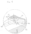
- FIG. 1 is a side, partial cross-sectional view of a pipe wrench according to the invention.
- FIG. 2 is an end cross-sectional view of the slidable knob mounted on the handle of the pipe wrench.
- FIG. 3 is an end cross-sectional view of the joint of the movable jaw with the handle of the pipe wrench.
- FIG. 4 is an enlarged view of the slidable knob depicted in FIG. 1.
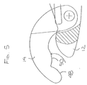
- FIG. 5 is a side view of an alternative jaw arrangement for a multi-purpose wrench according to the invention.
- the present invention is directed to a pipe wrench or other multi-purpose wrench having a locking mechanism for holding the jaws open during use.
- the pipe wrench comprises a handle 10 having a top edge 11 and a bottom edge 13 and fixed and moveable jaws 12 and 14 at the distal end of the handle.
- the fixed and moveable jaws each have an outer edge 15 and 16 and an inner, contact edge 17 and 18 for contacting a pipe or other work surface.
- the jaws are mounted such that the outer edge 16 of the moveable jaw 14 corresponds to the top edge 11 of the handle and the outer edge 15 of the fixed jaw 12 corresponds to the bottom edge 13 of the handle.
- Teeth 19 are provided on the contact edges 17 and 18 to increase the friction between the contact edges and the pipe or other work surface.
- the contact edges 17 and 18 can be smooth without teeth.
- the fixed jaw 12 is unitary with the handle 10, although the fixed jaw can also be a separate piece fixedly attached to the handle, as would be recognized by one skilled in the art. Further, a plastic grip 8 or other cover is provided over the proximal end of the handle 10 for comfort.
- the handle 10 and fixed jaw 12 are formed a plurality of laminated layers 21 of cold rolled sheet metal steel with a plastic filler layer 23 between the laminated layers over a portion of the length of the handle, as shown in FIGs. 1 and 2.
- the number of laminated layers is selected to achieve the desired thickness of the wrench so that the wrench can accommodate a desired load.
- the plastic filler layer 23 has a thickness of approximately 0.31 inch (7.8 mm) and the laminated layers 21 on either side of the filler layer each have a total thickness of approximately 0.12 inch (3.0 mm) so that the handle has a total thickness of about 0.54 inch (13.8 mm).
- the moveable jaw 14 is rotatably mounted to the handle 10 by a pin 20 or any other suitable means, such as a screw, as shown in FIGs. 1 and 3.
- the plastic filler layer 23 terminates a portion of the way along the length of the handle at line 25.
- a space 27 is provided between the laminated layers 21 to accommodate the proximal end of the moveable jaw 14 as the jaw opens and closes, as described in more detail below.
- a washer and/or spacer 28 is provided near the pin 20 to enhance the free movement of the moveable jaw 14.
- a spring 22 is provided in the handle 10 for biasing the moveable jaw 14 toward the fixed jaw 12.
- the spring 22 is generally L-shaped, having a distal end 24 in contact with the moveable jaw 14 and a proximal end fixedly attached to the handle 10.
- any other biasing means capable of biasing the moveable jaw toward the fixed jaw could also be used, such as a spring having a shape different from the depicted embodiment.
- the contact edge 18 of the moveable jaw 14 is in contact with the contact edge 17 of the fixed jaw 12, forming a contact region.
- the force of the pipe against the contact region opens the jaws such that the pipe moves between the jaws.
- the force of the spring 22 on the moveable jaw 14 biases the moveable jaw toward the pipe. The user can then turn the pipe by turning the handle 10 of the wrench.
- the locking mechanism comprises a lever 30 (or other connector) extending through the handle 10, a slidable button 32 slidably mounted on the top edge 11 of the handle, and means for locking the slidable button in a fixed position to hold the moveable jaw in an open position.
- the term "open position" refers to the position that the moveable jaw is in when a pipe or other work piece can be removed from between the moveable jaw and fixed jaw.
- the lever 30 is bent, although, as would be recognized by one skilled in the art, the lever can also be straight.
- a spring 46 is provided between the button 32 and the top edge 11 of the handle 10.
- the lever 30 has a distal end 34 fixedly attached to the moveable jaw 14, preferably the proximal end of the moveable jaw, by a distal pin 36 or the like.
- the lever 30 has a proximal end 38 fixedly attached to the slidable button 32 by means of a proximal pin 40.
- the proximal pin 40 rides in a slot 42 in the handle, preferably a longitudinal slot.
- the term "longitudinal" in relation to the slot means that the slot has a proximal end and a distal end and extends generally along a portion of the length of the handle.
- the lever 30 can be connected to the slidable button 32 by any other suitable means, such as glue, weld, solder, a screw or the like, and a separate pin or other means for riding in the slot 42 is fixedly attached to the slidable button.
- the means for connecting the lever 30 to the slidable button 32 is the same as the means for riding in the slot 42.
- the slot 42 is generally parallel with the top edge 11 of the handle 10 along which the slidable button 32 moves.
- Proximal and distal grooves 44 and 45 extend downward (i.e., away from the top edge 11 ) from the slot 42.
- the grooves 44 and 45 are each provided at an angle ⁇ relative to the slot, as shown in FIG. 4, less than 90°, preferably ranging from about 60° to about 85°, more preferably between about 65 ° to 80°, still more preferably about 70°.
- the grooves can extend upward from the slot at an angle.
- the lever 30 moves proximally. Proximal movement of the lever 30 moves the proximal pin 40 proximally within the slot 42, and the slidable button 32 correspondingly moves proximally along the top edge 11 of the handle 10.
- the lever 30 could be replaced with any other rigid connector capable of translating movement of the moveable jaw 14 to the proximal pin 40 and slidable button 32.
- the user pushes downward on the slidable button 32, thereby forcing the proximal pin 40 into one of the grooves 44 and 45 and locking the moveable jaw 14 in an open position.
- the proximal pin is forced into the distal groove 45, and for larger pipes, the proximal pin is forced into the proximal groove 44.
- the user can then remove the wrench from the pipe without the moveable jaw 14 closing back onto the pipe
- the user need not directly exert a proximal force on the slidable button 32 by pulling the button proximally, which can be difficult depending on the size of the pipe, but can indirectly exert a proximal force on the button by pushing the wrench distally toward the pipe.
- the number of grooves can vary as desired For example, only one groove can be provided, or three or more grooves can be provided. Alternatively, no grooves can be provided, in which case the user can lock the moveable jaw 14 in place, once open, by holding the slidable button 32 in place. Even with this alternative design, it is unnecessary for the user to exert a direct proximal force on the moveable jaw with the button, but only for the user to hold the button in place once he indirectly exerts the force, as described above.
- the inner contact edge 18 of the moveable jaw 14 comprises at least two curved edges 48 and 50, as shown in FIG. 5.
- the two curved edges enhance the ability of the jaws 12 and 14 to close tightly upon the workpiece and hold it in place.
- the distal curved edge 48 preferably has a radius of curvature ranging from about 0.38 inch to about 0.52 inch, more preferably about 0.42 inch to about 0.48 inch, still more preferably about 0.46 inch.
- the proximal curved edge 50 preferably has a radius of curvature ranging from about 0.50 inch to about 0.70 inch, more preferably from about 0.56 inch to about 0.64 inch, still more preferably about 0.60 inch.
- the fixed jaw 12 has an inner contact edge 17 having a distal curved edge 52 that preferably has a radius of curvature ranging from about 0.55 inch to about 0.75 inch, preferably about 0.64 inch.
Landscapes
- Engineering & Computer Science (AREA)
- Mechanical Engineering (AREA)
- Details Of Spanners, Wrenches, And Screw Drivers And Accessories (AREA)
Abstract
Description
- The present invention is directed to a wrench, and more particularly to a wrench having a locking mechanism for holding open the jaws of the wrench for easy removal of a workpiece from the jaws.
- Previously, adjustable wrenches have been provided with a moveable jaw that permits use of the wrench with work pieces, e.g., pipes and nuts, of varying sizes. However, once the jaws of the wrench are closed on the work piece, the work piece can be removed only by manually opening the moveable jaw away from the work piece. Attempts have been made to provide wrenches where the user can open the moveable jaw without actually grasping and pulling the moveable jaw. However, in many such designs, a significant amount of force must nonetheless be exerted by the user to open the jaw.
- The present invention is directed to an improved wrench having a moveable jaw whereby minimal force is necessary to open the moveable jaw to remove the work piece. In one embodiment, the invention is directed to a wrench for applying a force to a work piece comprising a handle having proximal and distal ends and top and bottom edges. A fixed jaw is mounted at the distal end of the handle, and a moveable jaw is pivotally mounted at the distal end of the handle. A biasing means is mounted in the handle for biasing the moveable jaw toward the fixed jaw. A slidable button is mounted on the top edge of the handle. A connector is provided having a distal end fixedly attached to the moveable jaw and a proximal end fixedly attached to the slidable button. The wrench further comprises means for locking the slidable button in a fixed position to hold the moveable jaw in an open position.
- In a preferred embodiment, the invention is directed to a Wrench having a handle and fixed and moveable jaws, as described above. The handle has a slot extending therethrough with a groove extending downward from the slot. A spring is mounted in the handle having a distal end in contact with the moveable jaw for biasing the moveable jaw toward the fixed jaw. A slidable button is mounted on the top edge of the handle, with a spring mounted between the slidable button and the top edge of the handle. The wrench further comprises a connector having a distal end fixedly attached to the moveable jaw and a proximal end fixedly attached to the slidable button by a pin. In operation, the pin rides in the slot and fits in the groove.
- By the above designs, when the user desires to remove the wrench from the work piece, he pushes the wrench distally toward the work piece. The work piece exerts a force on the proximal end of the moveable jaw, counteracting the biasing force of the spring and thereby opening the jaw. When the jaw opens, the connector is moved proximally, thus moving the slidable button proximally. This movement causes the pin to move proximally within the slot. When the moveable jaw is opened far enough for the work piece to be removed, the user pushes downward on the slidable button, thereby holding open the moveable jaw. Further, in the preferred embodiment, pushing on the slidable button forces the pin into the groove, further locking the moveable jaw in an open position so that, even if the user releases the slidable button, the moveable jaw will remain open.
- These and other features of the advantages of the present invention will be better understood by reference to the following detailed description when considered in conjunction with the accompanying drawings wherein:
- FIG. 1 is a side, partial cross-sectional view of a pipe wrench according to the invention.
- FIG. 2 is an end cross-sectional view of the slidable knob mounted on the handle of the pipe wrench.
- FIG. 3 is an end cross-sectional view of the joint of the movable jaw with the handle of the pipe wrench.
- FIG. 4 is an enlarged view of the slidable knob depicted in FIG. 1.
- FIG. 5 is a side view of an alternative jaw arrangement for a multi-purpose wrench according to the invention.
- The present invention is directed to a pipe wrench or other multi-purpose wrench having a locking mechanism for holding the jaws open during use. As shown in FIG. 1, the pipe wrench comprises a handle 10 having a top edge 11 and a
bottom edge 13 and fixed andmoveable jaws outer edge 15 and 16 and an inner,contact edge outer edge 16 of themoveable jaw 14 corresponds to the top edge 11 of the handle and the outer edge 15 of thefixed jaw 12 corresponds to thebottom edge 13 of the handle. Teeth 19 are provided on thecontact edges contact edges - In the depicted embodiment, the
fixed jaw 12 is unitary with the handle 10, although the fixed jaw can also be a separate piece fixedly attached to the handle, as would be recognized by one skilled in the art. Further, a plastic grip 8 or other cover is provided over the proximal end of the handle 10 for comfort. - In a preferred embodiment, the handle 10 and
fixed jaw 12 are formed a plurality of laminatedlayers 21 of cold rolled sheet metal steel with aplastic filler layer 23 between the laminated layers over a portion of the length of the handle, as shown in FIGs. 1 and 2. The number of laminated layers is selected to achieve the desired thickness of the wrench so that the wrench can accommodate a desired load. For example, in the depicted embodiment, theplastic filler layer 23 has a thickness of approximately 0.31 inch (7.8 mm) and the laminatedlayers 21 on either side of the filler layer each have a total thickness of approximately 0.12 inch (3.0 mm) so that the handle has a total thickness of about 0.54 inch (13.8 mm). - The
moveable jaw 14 is rotatably mounted to the handle 10 by apin 20 or any other suitable means, such as a screw, as shown in FIGs. 1 and 3. As best shown in FIG. 1, theplastic filler layer 23 terminates a portion of the way along the length of the handle atline 25. Aspace 27 is provided between the laminatedlayers 21 to accommodate the proximal end of themoveable jaw 14 as the jaw opens and closes, as described in more detail below. If desired, a washer and/orspacer 28 is provided near thepin 20 to enhance the free movement of themoveable jaw 14. - A
spring 22 is provided in the handle 10 for biasing themoveable jaw 14 toward the fixedjaw 12. Thespring 22 is generally L-shaped, having a distal end 24 in contact with themoveable jaw 14 and a proximal end fixedly attached to the handle 10. As would be recognized by one skilled in the art, any other biasing means capable of biasing the moveable jaw toward the fixed jaw could also be used, such as a spring having a shape different from the depicted embodiment. - In use, when the wrench is in a neutral position, the
contact edge 18 of themoveable jaw 14 is in contact with thecontact edge 17 of the fixedjaw 12, forming a contact region. As the wrench is pushed against a pipe or other work surface, such that the distal end of the contact region is in contact with the pipe, the force of the pipe against the contact region opens the jaws such that the pipe moves between the jaws. Once the pipe is between the jaws, the force of thespring 22 on themoveable jaw 14 biases the moveable jaw toward the pipe. The user can then turn the pipe by turning the handle 10 of the wrench. - When the user desires to remove the wrench from the pipe, he pushes the wrench distally toward the pipe. The pipe exerts a force on the proximal end of the
contact edge 18 of themoveable jaw 14, counteracting the force of the spring and thereby opening the jaw. - To hold the
moveable jaw 14 open so that the user can pull the wrench proximally away from the pipe without the moveable jaw closing on the pipe, a locking mechanism is provided. The locking mechanism comprises a lever 30 (or other connector) extending through the handle 10, aslidable button 32 slidably mounted on the top edge 11 of the handle, and means for locking the slidable button in a fixed position to hold the moveable jaw in an open position. As used herein, the term "open position" refers to the position that the moveable jaw is in when a pipe or other work piece can be removed from between the moveable jaw and fixed jaw. - In the depicted embodiment, the
lever 30 is bent, although, as would be recognized by one skilled in the art, the lever can also be straight. As shown in FIGs. 1 and 2, aspring 46 is provided between thebutton 32 and the top edge 11 of the handle 10. Thelever 30 has a distal end 34 fixedly attached to themoveable jaw 14, preferably the proximal end of the moveable jaw, by a distal pin 36 or the like. Thelever 30 has aproximal end 38 fixedly attached to theslidable button 32 by means of aproximal pin 40. - The
proximal pin 40 rides in aslot 42 in the handle, preferably a longitudinal slot. As used herein, the term "longitudinal" in relation to the slot means that the slot has a proximal end and a distal end and extends generally along a portion of the length of the handle. Alternatively, thelever 30 can be connected to theslidable button 32 by any other suitable means, such as glue, weld, solder, a screw or the like, and a separate pin or other means for riding in theslot 42 is fixedly attached to the slidable button. For example, However, in a preferred embodiment, the means for connecting thelever 30 to theslidable button 32 is the same as the means for riding in theslot 42. - The
slot 42 is generally parallel with the top edge 11 of the handle 10 along which theslidable button 32 moves. Proximal anddistal grooves slot 42. Thegrooves - In use, as the pipe or other work surface is forced against the proximal end of the
contact edge 18 of themoveable jaw 14, opening the jaw, thelever 30 moves proximally. Proximal movement of thelever 30 moves theproximal pin 40 proximally within theslot 42, and theslidable button 32 correspondingly moves proximally along the top edge 11 of the handle 10. As would be recognized by one skilled in the art, thelever 30 could be replaced with any other rigid connector capable of translating movement of themoveable jaw 14 to theproximal pin 40 andslidable button 32. When themoveable jaw 14 is opened far enough for the pipe to be removed, the user pushes downward on theslidable button 32, thereby forcing theproximal pin 40 into one of thegrooves moveable jaw 14 in an open position. For smaller pipes, the proximal pin is forced into thedistal groove 45, and for larger pipes, the proximal pin is forced into theproximal groove 44. The user can then remove the wrench from the pipe without themoveable jaw 14 closing back onto the pipe As a result, the user need not directly exert a proximal force on theslidable button 32 by pulling the button proximally, which can be difficult depending on the size of the pipe, but can indirectly exert a proximal force on the button by pushing the wrench distally toward the pipe. - As would be recognized by one skilled in the art, the number of grooves can vary as desired For example, only one groove can be provided, or three or more grooves can be provided. Alternatively, no grooves can be provided, in which case the user can lock the
moveable jaw 14 in place, once open, by holding theslidable button 32 in place. Even with this alternative design, it is unnecessary for the user to exert a direct proximal force on the moveable jaw with the button, but only for the user to hold the button in place once he indirectly exerts the force, as described above. - In a particularly preferred embodiment, the
inner contact edge 18 of themoveable jaw 14 comprises at least twocurved edges 48 and 50, as shown in FIG. 5. The two curved edges enhance the ability of thejaws curved edge 48 preferably has a radius of curvature ranging from about 0.38 inch to about 0.52 inch, more preferably about 0.42 inch to about 0.48 inch, still more preferably about 0.46 inch. The proximal curved edge 50 preferably has a radius of curvature ranging from about 0.50 inch to about 0.70 inch, more preferably from about 0.56 inch to about 0.64 inch, still more preferably about 0.60 inch. In the depicted embodiment, the fixedjaw 12 has aninner contact edge 17 having a distal curved edge 52 that preferably has a radius of curvature ranging from about 0.55 inch to about 0.75 inch, preferably about 0.64 inch. - The preceding description has been presented with reference to presently preferred embodiments of the invention. Workers skilled in the art and technology to which this invention pertains will appreciate that alterations and changes in the described structure may be practiced without meaningfully departing from the principal, spirit and scope of this invention.
- Accordingly, the foregoing description should not be read as pertaining only to the precise structures described and illustrated in the accompanying drawings, but rather should be read consistent with and as support to the following claims which are to have their fullest and fair scope.
Claims (33)
- A wrench for applying a force to a work piece, the wrench comprising:a handle having proximal and distal ends and top and bottom edges;a fixed jaw mounted at the distal end of the handle having an inner, contact surface for contacting the work piece;a moveable jaw pivotally mounted at the distal end of the handle having an inner, contact surface for contacting the work piece;a biasing means mounted in the handle for biasing the moveable jaw toward the fixed jaw;a slidable button mounted on the top edge of the handle;a connector having a distal end fixedly attached to the moveable jaw and a proximal end fixedly attached to the slidable button; andmeans for locking the slidable button in a fixed position to hold the moveable jaw in an open position.
- A wrench according to claim 1, further comprising a spring mounted between the slidable button and the top edge of the handle.
- A wrench according to claim 1, wherein the means for locking the slidable button comprises a slot extending through the handle and a means for riding in the slot fixedly attached to the slidable button.
- A wrench according to claim 3, wherein the slot is a longitudinal slot.
- A wrench according to claim 3, wherein the slot is generally parallel to the top edge of the handle.
- A wrench according to claim 3, wherein the slot has at least one groove extending therefrom.
- A wrench according to claim 6, wherein the groove is at an angle α relative to the slot less than 90°.
- A wrench according to claim 6, wherein the groove is at an angle α relative to the slot ranging from about 60° to about 85°.
- A wrench according to claim 6, wherein the groove extends downward from the slot.
- A wrench according to claim 8, wherein the groove is at an angle α relative to the slot ranging from about 60° to about 85°.
- A wrench according to claim 3, wherein the slot has two grooves extending downward therefrom.
- A wrench according to claim 3, wherein the means for riding in the slot is fixedly attached to the lever.
- A wrench according to claim 3, wherein the means for riding in the slot comprises a pin fixedly attached to the lever and to the slidable button.
- A wrench for applying a force to a work piece, the wrench comprising:a handle having proximal and distal ends, top and bottom edges and a slot extending therethrough;a fixed jaw mounted at the distal end of the handle having an inner, contact surface for contacting the work piece;a moveable jaw pivotally mounted at the distal end of the handle having an inner, contact surface for contacting the work piece;a biasing means mounted in the handle for biasing the moveable jaw toward the fixed jaw;a slidable button mounted on the top edge of the handle;a connector having a distal end fixedly attached to the moveable jaw and a proximal end fixedly attached to the slidable button; andmeans for riding in the slot connected to the slidable button.
- A wrench according to claim 14, wherein the means for riding in the slot comprises a pin.
- A wrench according to claim 14, wherein the means for riding in the slot is a pin attached to the lever.
- A wrench according to claim 14, wherein the biasing means comprises a spring.
- A wrench according to claim 14, wherein the biasing means comprises a generally L-shaped spring.
- A wrench according to claim 14, further comprising a spring mounted between the slidable button and the top edge of the wrench.
- A wrench according to claim 14, wherein the slot has at least one groove extending therefrom.
- A wrench according to claim 20, wherein the groove extends downward and is at an angle α relative to the slot less than 90°.
- A wrench according to claim 20, wherein the groove extends downward and is at an angle α relative to the slot ranging from about 60° to about 85°.
- A wrench according to claim 14, wherein the slot has two grooves extending downward therefrom.
- A wrench for applying a force to a work piece, the wrench comprising:a handle having proximal and distal ends, top and bottom edges and a slot extending therethrough with a groove extending downward from the slot;a fixed jaw mounted at the distal end of the handle having an inner, contact surface for contacting the work piece;a moveable jaw pivotally mounted at the distal end of the handle having an inner, contact surface for contacting the work piece;a spring mounted in the handle having a distal end in contact with the moveable jaw for biasing the moveable jaw toward the fixed jaw;a slidable button mounted on the top edge of the handle;a spring mounted between the slidable button and the top edge of the handle;a connector having a distal end fixedly attached to the moveable jaw and a proximal end fixedly attached to the slidable button by a pin,wherein, in operation, the pin rides in the slot and fits in the groove.
- A wrench for applying a force to a work piece, the wrench comprising:a handle having proximal and distal ends;a fixed jaw mounted at the distal end of the handle having an inner, contact surface for contacting the work piece;a moveable jaw pivotally mounted at the distal end of the handle having an inner, contact surface for contacting the work piece, wherein the inner contact surface comprises a distal convex edge and a proximal convex edge.
- A wrench according to claim 25, wherein the inner, contact surface of the fixed jaw comprises a distal convex edge.
- A wrench according to claim 25, wherein the distal convex edge lids a radius of curvature ranging from about 0.38 inch to about 0.52 inch.
- A wrench according to claim 25, wherein the distal convex edge has a radius of curvature ranging from about 0.42 inch to about 0.48 inch.
- A wrench according to claim 25, wherein the proximal convex edge has a radius of curvature ranging from about 0.50 inch to about 0.70 inch.
- A wrench according to claim 25, wherein the proximal convex edge has a radius of curvature ranging from about 0.56 inch to about 0.64 inch.
- A wrench according to claim 25, wherein the distal convex edge has a radius of curvature ranging from about 0.38 inch to about 0.52 inch, and the proximal convex edge has a radius of curvature ranging from about 0.50 inch to about 0.70 inch.
- A wrench according to claim 25, wherein the distal convex edge has a radius of curvature ranging from about 0.42 inch to about 0.48 inch, and the proximal convex edge has a radius of curvature ranging from about 0.56 inch to about 0.64 inch.
- A hand tool, such as a wrench, grip or spanner, for workpiece gripping, 'purchase', grasping and/or leverage; comprising a handle, with a workpiece contact jaw at one end; a pivoted workpiece contact jaw; with biasing means, towards the one jaw; a slidable member, connected to the movable jaw, with locking means, to hold open the movable jaw, relative to the one jaw.
Applications Claiming Priority (2)
| Application Number | Priority Date | Filing Date | Title |
|---|---|---|---|
| US09/499,797 US6349621B1 (en) | 2000-02-08 | 2000-02-08 | Wrench |
| US499797 | 2000-02-08 |
Publications (2)
| Publication Number | Publication Date |
|---|---|
| EP1123781A2 true EP1123781A2 (en) | 2001-08-16 |
| EP1123781A3 EP1123781A3 (en) | 2003-01-22 |
Family
ID=23986766
Family Applications (1)
| Application Number | Title | Priority Date | Filing Date |
|---|---|---|---|
| EP00308411A Withdrawn EP1123781A3 (en) | 2000-02-08 | 2000-09-25 | Wrench |
Country Status (3)
| Country | Link |
|---|---|
| US (1) | US6349621B1 (en) |
| EP (1) | EP1123781A3 (en) |
| TW (1) | TW430596B (en) |
Cited By (1)
| Publication number | Priority date | Publication date | Assignee | Title |
|---|---|---|---|---|
| EP1525951A2 (en) * | 2003-10-22 | 2005-04-27 | Intercable Srl | Tool for hexagonal screw-threaded cable fittings |
Families Citing this family (20)
| Publication number | Priority date | Publication date | Assignee | Title |
|---|---|---|---|---|
| NZ513676A (en) * | 2001-08-21 | 2001-09-28 | Denis Lee Stewart | Improvements to a wrench |
| US7059221B2 (en) * | 2003-05-09 | 2006-06-13 | Simon David A | Wrench |
| US7131355B2 (en) * | 2003-12-02 | 2006-11-07 | Steven Andrew Williams | Lightweight wrench |
| TW201410394A (en) * | 2012-09-14 | 2014-03-16 | Xin-Tong Zheng | Toggle-type adjustable spanner |
| US11235443B2 (en) | 2013-03-26 | 2022-02-01 | Milwaukee Electric Tool Corporation | Pipe wrench |
| US9205539B2 (en) | 2013-04-01 | 2015-12-08 | Emerson Electric Co. | Wrench |
| US9434055B2 (en) | 2013-04-01 | 2016-09-06 | Ridge Tool Company | Replaceable gripping inserts for wrenches |
| USD717619S1 (en) | 2013-04-01 | 2014-11-18 | Ridge Tool Company | Tool handle |
| USD739192S1 (en) | 2013-04-01 | 2015-09-22 | Ridge Tool Company | Insert for tool |
| USD742707S1 (en) | 2013-04-01 | 2015-11-10 | Ridge Tool Company | Tool head |
| US9676091B2 (en) * | 2014-07-02 | 2017-06-13 | Test Rite International Co., Ltd | 10-in-1 multiple function wrench |
| USD750944S1 (en) | 2014-08-29 | 2016-03-08 | Ridge Tool Company | Wrench |
| USD748958S1 (en) | 2014-08-29 | 2016-02-09 | Ridge Tool Company | Wrench |
| USD749924S1 (en) | 2014-08-29 | 2016-02-23 | Ridge Tool Company | Wrench |
| TWI580529B (en) * | 2015-07-17 | 2017-05-01 | A wrench that repeats the operation | |
| TW201714713A (en) * | 2015-10-20 | 2017-05-01 | yu-xiang Huang | Clamp body structure whereby screw members of different specifications or tubes of different diameters can be clamped between the third body and the first body |
| US10994405B2 (en) | 2017-05-11 | 2021-05-04 | Milwaukee Electric Tool Corporation | Pipe wrench |
| WO2019191655A1 (en) | 2018-03-30 | 2019-10-03 | Milwaukee Electric Tool Corporation | Pipe wrench |
| EP4192651A1 (en) | 2020-08-04 | 2023-06-14 | Milwaukee Electric Tool Corporation | Extendable wrench |
| TWI758154B (en) * | 2021-04-06 | 2022-03-11 | 鴻安國際興業有限公司 | Speed wrench |
Citations (7)
| Publication number | Priority date | Publication date | Assignee | Title |
|---|---|---|---|---|
| US1576918A (en) * | 1924-04-17 | 1926-03-16 | Lidell Andrew Emanuel | Wrench |
| US2467658A (en) * | 1946-02-07 | 1949-04-19 | Francis J Carnelli | Self-adjusting wrench |
| US4651597A (en) * | 1984-08-13 | 1987-03-24 | Yang Tai Her | Speed wrench equipped with jaw auxiliary operational mechanism |
| DE19612758C1 (en) * | 1996-03-29 | 1997-09-11 | Gernot Hirse | Self-clamping tightening spanner with fixed and movable clamping jaw |
| US5746097A (en) * | 1997-02-19 | 1998-05-05 | Mccann; Frank | Wrench having a spring biased jaw |
| DE19747536A1 (en) * | 1997-10-28 | 1999-05-06 | Gernot Hirse | Open-ended wrench |
| DE29904045U1 (en) * | 1999-03-05 | 1999-06-17 | Kao, Hong-Tien, Taichung | Improved wrench |
Family Cites Families (28)
| Publication number | Priority date | Publication date | Assignee | Title |
|---|---|---|---|---|
| US262840A (en) | 1882-08-15 | Wrench | ||
| US343038A (en) | 1886-06-01 | Wrench | ||
| US676318A (en) | 1901-03-08 | 1901-06-11 | W W Whitehead Company | Wrench. |
| US739316A (en) | 1903-02-20 | 1903-09-22 | David H Irland | Pipe-wrench. |
| US800850A (en) | 1905-05-23 | 1905-10-03 | Irland Pipe Wrench Company | Pipe-wrench. |
| US868126A (en) | 1905-10-05 | 1907-10-15 | Irland Pipe Wrench Company | Pipe-wrench. |
| US831750A (en) | 1905-10-30 | 1906-09-25 | John T Clarke | Pipe-wrench. |
| US874545A (en) | 1906-04-23 | 1907-12-24 | Elbridge Llewellyn Scribner | Pipe-wrench. |
| US897665A (en) | 1907-01-02 | 1908-09-01 | De Leonard Rugg | Automatic wrench. |
| US868127A (en) | 1907-02-28 | 1907-10-15 | Irland Pipe Wrench Company | Pipe-wrench. |
| US937959A (en) | 1908-01-22 | 1909-10-26 | Joseph E Richards | Pipe-wrench. |
| US970731A (en) | 1910-01-17 | 1910-09-20 | W F Greenleaf | Pipe-wrench. |
| US1634908A (en) | 1924-03-03 | 1927-07-05 | Masterench Corp | Wrench |
| US1627035A (en) | 1926-02-16 | 1927-05-03 | Herman C Jahn | Wrench |
| GB333103A (en) | 1929-10-11 | 1930-08-07 | Gwilym Powell | Improvements in and connected with wrenches, spanners or the like |
| US1885616A (en) | 1931-04-09 | 1932-11-01 | Masterench Corp | Wrench |
| US2028406A (en) | 1935-01-16 | 1936-01-21 | Masterench Corp | Double jaw wrench |
| US2154531A (en) * | 1936-12-09 | 1939-04-18 | Matthew J Roche | Gripping device |
| US2417085A (en) | 1941-12-15 | 1947-03-11 | Byron Jackson Co | Pipe tong |
| US2618996A (en) | 1946-08-01 | 1952-11-25 | George T Logan | Nonslip ratcheting wrench having double-hexagon-spaced jaw-face grooves |
| US2623428A (en) | 1947-04-09 | 1952-12-30 | John V Larson | Self-adjusting pipe wrench of a spring impelled trigger actuator type |
| US2684607A (en) | 1950-02-17 | 1954-07-27 | Victor S Lundell | Swingable jaw wrench |
| US2655064A (en) | 1951-11-29 | 1953-10-13 | Otis W Simon | Ratcheting wrench |
| AU1708883A (en) | 1982-07-09 | 1984-02-08 | Nitschmann, F. | Ratschenartiger maulschlussel |
| USD287928S (en) | 1984-01-25 | 1987-01-27 | Top Kogyo Co., Ltd. | Pivoted jaw wrench |
| US4773287A (en) | 1987-02-17 | 1988-09-27 | Clarke Roger S | Open-ended ratchet wrench |
| CA2069265A1 (en) * | 1991-08-26 | 1993-02-27 | Young S. Woo | Pipe wrench |
| US5396820A (en) * | 1993-01-15 | 1995-03-14 | Baker; David R. | Open end wrench with removable handle |
-
2000
- 2000-02-08 US US09/499,797 patent/US6349621B1/en not_active Expired - Lifetime
- 2000-07-04 TW TW089110029A patent/TW430596B/en not_active IP Right Cessation
- 2000-09-25 EP EP00308411A patent/EP1123781A3/en not_active Withdrawn
Patent Citations (7)
| Publication number | Priority date | Publication date | Assignee | Title |
|---|---|---|---|---|
| US1576918A (en) * | 1924-04-17 | 1926-03-16 | Lidell Andrew Emanuel | Wrench |
| US2467658A (en) * | 1946-02-07 | 1949-04-19 | Francis J Carnelli | Self-adjusting wrench |
| US4651597A (en) * | 1984-08-13 | 1987-03-24 | Yang Tai Her | Speed wrench equipped with jaw auxiliary operational mechanism |
| DE19612758C1 (en) * | 1996-03-29 | 1997-09-11 | Gernot Hirse | Self-clamping tightening spanner with fixed and movable clamping jaw |
| US5746097A (en) * | 1997-02-19 | 1998-05-05 | Mccann; Frank | Wrench having a spring biased jaw |
| DE19747536A1 (en) * | 1997-10-28 | 1999-05-06 | Gernot Hirse | Open-ended wrench |
| DE29904045U1 (en) * | 1999-03-05 | 1999-06-17 | Kao, Hong-Tien, Taichung | Improved wrench |
Cited By (2)
| Publication number | Priority date | Publication date | Assignee | Title |
|---|---|---|---|---|
| EP1525951A2 (en) * | 2003-10-22 | 2005-04-27 | Intercable Srl | Tool for hexagonal screw-threaded cable fittings |
| EP1525951A3 (en) * | 2003-10-22 | 2006-02-08 | Intercable Srl | Tool for hexagonal screw-threaded cable fittings |
Also Published As
| Publication number | Publication date |
|---|---|
| US6349621B1 (en) | 2002-02-26 |
| TW430596B (en) | 2001-04-21 |
| EP1123781A3 (en) | 2003-01-22 |
Similar Documents
| Publication | Publication Date | Title |
|---|---|---|
| US6349621B1 (en) | Wrench | |
| US6626070B2 (en) | Compound toggle link retention mechanism | |
| US5020399A (en) | Self-adjusting pliers with curved handles | |
| US7249542B2 (en) | Self-adjusting variable grip locking plier for gripping a workpiece | |
| US7389714B1 (en) | Dual action locking pliers | |
| US6131491A (en) | Self-locking chuck key | |
| US6708588B2 (en) | Self adjusting mechanism for locking plier, wrench, or other tool | |
| CN113498368B (en) | Locking pliers | |
| GB2306377A (en) | Pliers for gripping workpieces of different sizes | |
| US5535650A (en) | Adjustable plier wrench hand tool | |
| US8534656B2 (en) | Clamp arrangement | |
| US7721630B2 (en) | Automatic sizing one-handed locking pliers | |
| US20100018362A1 (en) | Locking pliers | |
| KR19990028958A (en) | Locking grip | |
| US20100282032A1 (en) | Self-adjusting pliers | |
| US4524648A (en) | Fixation tweezers | |
| US6938525B2 (en) | One hand pipe wrench | |
| US6155142A (en) | Pliers with force augmentation and self-adjustment capability | |
| US6006633A (en) | Pliers (1) | |
| US20100192735A1 (en) | Release auto-grip locking tool | |
| JPH08308654A (en) | Tool to clamp runner to drawer | |
| US5484135A (en) | Fish tape puller | |
| US20230381926A1 (en) | Adjustable plier with dual adjust | |
| EP4292761A1 (en) | Hand tool | |
| US6601479B1 (en) | Self adjusting locking pliers |
Legal Events
| Date | Code | Title | Description |
|---|---|---|---|
| PUAI | Public reference made under article 153(3) epc to a published international application that has entered the european phase |
Free format text: ORIGINAL CODE: 0009012 |
|
| AK | Designated contracting states |
Kind code of ref document: A2 Designated state(s): AT BE CH CY DE DK ES FI FR GB GR IE IT LI LU MC NL PT SE |
|
| AX | Request for extension of the european patent |
Free format text: AL;LT;LV;MK;RO;SI |
|
| PUAL | Search report despatched |
Free format text: ORIGINAL CODE: 0009013 |
|
| AK | Designated contracting states |
Kind code of ref document: A3 Designated state(s): AT BE CH CY DE DK ES FI FR GB GR IE IT LI LU MC NL PT SE |
|
| AX | Request for extension of the european patent |
Free format text: AL;LT;LV;MK;RO;SI |
|
| 17P | Request for examination filed |
Effective date: 20021224 |
|
| AKX | Designation fees paid |
Designated state(s): AT BE CH CY DE DK ES FI FR GB GR IE IT LI LU MC NL PT SE |
|
| 17Q | First examination report despatched |
Effective date: 20050120 |
|
| 17Q | First examination report despatched |
Effective date: 20050120 |
|
| STAA | Information on the status of an ep patent application or granted ep patent |
Free format text: STATUS: THE APPLICATION IS DEEMED TO BE WITHDRAWN |
|
| 18D | Application deemed to be withdrawn |
Effective date: 20070228 |