EP1123742B1 - Brausekopf - Google Patents
Brausekopf Download PDFInfo
- Publication number
- EP1123742B1 EP1123742B1 EP01101427A EP01101427A EP1123742B1 EP 1123742 B1 EP1123742 B1 EP 1123742B1 EP 01101427 A EP01101427 A EP 01101427A EP 01101427 A EP01101427 A EP 01101427A EP 1123742 B1 EP1123742 B1 EP 1123742B1
- Authority
- EP
- European Patent Office
- Prior art keywords
- plate
- spray
- nozzle plate
- nozzle
- fact
- Prior art date
- Legal status (The legal status is an assumption and is not a legal conclusion. Google has not performed a legal analysis and makes no representation as to the accuracy of the status listed.)
- Expired - Lifetime
Links
- 238000002156 mixing Methods 0.000 claims abstract description 33
- XLYOFNOQVPJJNP-UHFFFAOYSA-N water Substances O XLYOFNOQVPJJNP-UHFFFAOYSA-N 0.000 claims abstract description 21
- 239000007921 spray Substances 0.000 claims 18
- 238000000265 homogenisation Methods 0.000 description 3
- 238000005422 blasting Methods 0.000 description 1
- 238000010276 construction Methods 0.000 description 1
- 230000000694 effects Effects 0.000 description 1
- 238000000465 moulding Methods 0.000 description 1
- 238000005457 optimization Methods 0.000 description 1
- 238000007493 shaping process Methods 0.000 description 1
Images

Classifications
-
- B—PERFORMING OPERATIONS; TRANSPORTING
- B05—SPRAYING OR ATOMISING IN GENERAL; APPLYING FLUENT MATERIALS TO SURFACES, IN GENERAL
- B05B—SPRAYING APPARATUS; ATOMISING APPARATUS; NOZZLES
- B05B7/00—Spraying apparatus for discharge of liquids or other fluent materials from two or more sources, e.g. of liquid and air, of powder and gas
- B05B7/02—Spray pistols; Apparatus for discharge
- B05B7/04—Spray pistols; Apparatus for discharge with arrangements for mixing liquids or other fluent materials before discharge
- B05B7/0416—Spray pistols; Apparatus for discharge with arrangements for mixing liquids or other fluent materials before discharge with arrangements for mixing one gas and one liquid
- B05B7/0425—Spray pistols; Apparatus for discharge with arrangements for mixing liquids or other fluent materials before discharge with arrangements for mixing one gas and one liquid without any source of compressed gas, e.g. the air being sucked by the pressurised liquid
-
- B—PERFORMING OPERATIONS; TRANSPORTING
- B05—SPRAYING OR ATOMISING IN GENERAL; APPLYING FLUENT MATERIALS TO SURFACES, IN GENERAL
- B05B—SPRAYING APPARATUS; ATOMISING APPARATUS; NOZZLES
- B05B1/00—Nozzles, spray heads or other outlets, with or without auxiliary devices such as valves, heating means
- B05B1/14—Nozzles, spray heads or other outlets, with or without auxiliary devices such as valves, heating means with multiple outlet openings; with strainers in or outside the outlet opening
- B05B1/18—Roses; Shower heads
Definitions
- the invention relates to a shower head with a lower annular Base plate, from which the jets of water emerge, with one above it arranged annular jet disk, with one above the jet disk arranged annular nozzle plate and with between the bottom plate and Disc jet and / or arranged between the jet disc and nozzle plate annular sieves, wherein the nozzle plate at its top a plurality of Forms nozzles into which the water enters and through which the water in one of the Nozzle plate formed mixing chamber, and wherein the nozzles of the Nozzle plate with the openings of the jet disk and the bottom plate lie together so that they are aligned.
- Such a shower head is e.g. known from the document GB-A-2311474.
- the object of the invention is a shower head of the type mentioned so to improve that the exiting soft-rays high homogenization of air and water and in this optimal mixing in their Shape are stable.
- This object is achieved in that the mixing chamber the nozzle plate by radial vertical webs into individual mixing chambers is divided so that below each nozzle is a mixing chamber, the is separated by the webs of adjacent mixing chambers.
- the construction is of great simplicity.
- the effect of the nozzles of the nozzle plate can also be increased thereby if each nozzle into two to four, in particular sector-shaped openings is divided.
- the flow rate of the water in the nozzles is thereby even increased and so sucked in more air. It is also advantageous here when the mixing chambers are at least partially open to the outside to Suck air into the mixing chamber.
- the jet disk at its top and / or Bottom radial webs between their openings has to their upper and / or lower mixing chambers to form with the Align mixing chambers of the nozzle plate. This ensures that the individual water jets coming from the individual mixing chambers turn into individual mixing chambers of the jet disk, so that a further improvement of the mixing of water and air and thus one further optimization of the homogenization is achieved.
- top and / or bottom of the jet disk inside and / or outside Projections are formed in the recesses of the nozzle plate, the Base plate and / or the sieves eino form-fitting. Through this in Recesses reaching projections, the individual parts to each other be aligned exactly before being mounted in the bottom of the shower head become.
- a pre-assembled assembly holding each other is achieved when the Snap projections into or behind the recesses.
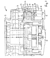
- the shower head 1 has an outer rotationally symmetrical housing 2, whose top has a water connection 3, with the shower head to Example of the handle of a hand shower is fastened.
- the shower head can but also used in other areas.
- this forms a coaxial middle Area 4, which can form a turbine for a pulsating jet.
- this area can also be closed or other types of Form water jets.
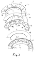
- the central region 4 is surrounded on the outside by an annular region 5, the is composed of the following parts, which are all arranged coaxially:
- a bottom plate 6 At the bottom is a bottom plate 6, with a variety of cylindrical paraxial passage openings 7, each of which mixed with air Water jet emerges.
- an annular flat sieve 8 Over the bottom plate 6 is an annular flat sieve 8 and above a jet disk 9.
- a second Sieve 10 is shaped in the same way as the first sieve 8.
- a nozzle plate 11th Over the sieve 10 is a nozzle plate 11th
- the nozzle plate 11 forms on its upper side an annular plate 12, whose Top and bottom is perpendicular to the axis of the shower head.
- nozzles 13 are arranged at regular intervals, in the Embodiment each of four sector-shaped openings 14th are composed.
- the water from above follows down through to get into a mixing chamber 15 of the nozzle plate 11.
- the edge cross section in the form of an inverted "U's" designed nozzle plate 11 forms on its underside for each nozzle 13 a separate mixing chamber, in each case a vertical radial web 16 is formed between two nozzles is.
- the nozzle plate 11 forms on its underside 14th Mixing chambers 15 corresponding to the fourteen nozzles 13th
- the outer leg of the cross-sectionally U-shaped underside of the Nozzle plate 11 is made shorter than the inner, so that the Nozzle plate on the outside forms an annular feed opening 17 through which the stream of water flowing through the nozzle plate sucks air laterally.
- the bottom plate 6 forms a gap-shaped with the housing wall Interspace 18 through which air can be sucked from below.
- the jet emerging from the jet disk 9 passes after passing through the Siebes 8 in the passage opening 7 of the bottom plate 6, wherein the upper edge of Passage opening 7 has a chamfer 20 to an optimal entry and a to create good shaping of the beam.
- the passage openings 7 of Base plate 6 thus form the well-mixed jet to him afterwards to let escape.
- the openings or nozzles 13 of the nozzle plate 11, the openings 19 of the Blasting disk 9 and the passage openings 7 of the bottom plate 6 are in this Parts in the same number exist and are aligned exactly one above the other, whereby also the mixing chambers are aligned with each other, so that an optimal Forming and mixing of each beam is guaranteed.
- the Projections 21 may additionally or alternatively also on the outside and furthermore additionally or alternatively on the base plate 6 or on the jet plate 9 be formed to be in corresponding recesses 22 of the other parts especially einrastend conveyo.
Landscapes
- Nozzles (AREA)
- Massaging Devices (AREA)
- Cylinder Crankcases Of Internal Combustion Engines (AREA)
- Sewing Machines And Sewing (AREA)
Description
- Fig. 1
- einen axialen Schnitt durch den Brausekopf,
- Fig. 2
- eine perspektivische Ansicht der halben Düsenplatte,
- Fig. 3
- eine perspektivische Explosionsdarstellung aller fünf Teile des unteren ringförmigen Bereichs.
Claims (9)
- Brausekopf mit einer unteren ringförmigen Bodenplatte (6), aus der die Wasserstrahlen austreten, mit einer darüber angeordneten ringförmigen Strahlscheibe (9), mit einer über der Strahlscheibe angeordneten ringförmigen Düsenplatte (11) und mit zwischen Bodenplatte und Strahlscheibe und/oder zwischen Strahlscheibe und Düsenplatte angeordneten ringförmigen Sieben (8, 10), wobei die Düsenplatte (11) an ihrer Oberseite eine Vielzahl von Düsen (13) bildet, in die das Wasser eintritt und durch die das Wasser in eine von der Düsenplatte gebildete Mischkammer gelangt, und wobei die Düsen (13) der Düsenplatte (11) mit den Durchtrittsöffnungen (19) der Strahlscheibe (9) und der Bodenplatte (6) so untereinander liegen, dass sie miteinander fluchten, dadurch gekennzeichnet, dass die Mischkammer (15) der Düsenplatte (11) durch radiale senkrechte Stege (16) in einzelne Mischkammern (15) derart aufgeteilt ist, dass unterhalb jeder Düse (13) eine Mischkammer (15) liegt, die durch die Stege (16) von benachbarten Mischkammern getrennt ist.
- Brausekopf nach Anspruch 1,dadurch gekennzeichnet, dass der Durchflußquerschnitt jeder Düse (13) der Düsenplatte (11) in zwei bis acht insbesondere kreis-, ellipsen- oder sektorenförmige Öffnungen (14) unterteilt ist.
- Brausekopf nach Anspruch 1 oder 2, dadurch gekennzeichnet, dass die Mischkammern (15) zur Außenseite hin zumindest teilweise offen (17) sind, um Luft in die Mischkammer anzusaugen.
- Brausekopf nach einem der vorherigen Ansprüche, dadurch gekennzeichnet, dass die Strahlscheibe (9) an ihrer Ober- und/oder Unterseite radiale Stege zwischen ihren Durchtrittsöffnungen aufweist, um an ihrer Ober- und/oder Unterseite Mischkammern zu bilden, die mit den Mischkammern (15) der Düsenplatte (11) fluchten.
- Brausekopf nach einem der vorherigen Ansprüche, dadurch gekennzeichnet, dass die Durchtrittsöffnungen (7) der Bodenplatte (6) am oberen Rand eine Fase (20) bilden.
- Brausekopf nach einem der vorherigen Ansprüche, dadurch gekennzeichnet, dass an der Unterseite der Düsenplatte (11) innen und/oder außen Vorsprünge (21) angeformt sind, die in Ausnehmungen (22) der Strahlscheibe (9), der Bodenplatte (6) und/oder der Siebe (8, 10) formschlüssig einliegen.
- Brausekopf nach einem der vorherigen Ansprüche, dadurch gekennzeichnet, dass an der Oberseite der Bodenplatte (6) innen und/oder außen Vorsprünge (21) angeformt sind, die in Ausnehmungen (22) der Düsenplatte (11) der Strahlscheibe (9) und/oder der Siebe (8, 10) formschlüssig einliegen.
- Brausekopf nach einem der vorherigen Ansprüche, dadurch gekennzeichnet, dass an der Ober- und/oder Unterseite der Strahlscheibe (9) innen und/oder außen Vorsprünge (21) angeformt sind, die in Ausnehmungen (22) der Düsenplatte (11), der Bodenplatte (6) und/oder der Siebe (8, 10) formschlüssig einliegen.
- Brausekopf nach einem der Ansprüche 6 bis 8, dadurch gekennzeichnet, dass die Vorsprünge (21) in oder hinter den Ausnehmungen (22) einrasten.
Applications Claiming Priority (2)
| Application Number | Priority Date | Filing Date | Title |
|---|---|---|---|
| DE10005098 | 2000-02-07 | ||
| DE10005098A DE10005098A1 (de) | 2000-02-07 | 2000-02-07 | Brausekopf |
Publications (4)
| Publication Number | Publication Date |
|---|---|
| EP1123742A2 EP1123742A2 (de) | 2001-08-16 |
| EP1123742A3 EP1123742A3 (de) | 2004-03-17 |
| EP1123742B1 true EP1123742B1 (de) | 2005-05-04 |
| EP1123742B2 EP1123742B2 (de) | 2012-04-11 |
Family
ID=7629939
Family Applications (1)
| Application Number | Title | Priority Date | Filing Date |
|---|---|---|---|
| EP01101427A Expired - Lifetime EP1123742B2 (de) | 2000-02-07 | 2001-01-23 | Brausekopf |
Country Status (3)
| Country | Link |
|---|---|
| EP (1) | EP1123742B2 (de) |
| AT (1) | ATE294643T1 (de) |
| DE (2) | DE10005098A1 (de) |
Cited By (1)
| Publication number | Priority date | Publication date | Assignee | Title |
|---|---|---|---|---|
| USD694366S1 (en) | 2011-01-14 | 2013-11-26 | Kohler Co. | Faucet |
Families Citing this family (1)
| Publication number | Priority date | Publication date | Assignee | Title |
|---|---|---|---|---|
| CN103320784B (zh) * | 2013-04-27 | 2015-08-26 | 浙江工业大学 | 宽度可调节的侧向送粉喷嘴 |
Family Cites Families (8)
| Publication number | Priority date | Publication date | Assignee | Title |
|---|---|---|---|---|
| US3633824A (en) † | 1969-07-08 | 1972-01-11 | Elic P Aghnides | Spray-producing device in which the output jets are aerated |
| DE7814613U1 (de) * | 1978-05-13 | 1978-12-07 | Guenther Rathsack Ingenieurtechnik, 2000 Hamburg | Handbrause |
| US4733818A (en) † | 1981-06-01 | 1988-03-29 | Aghnides Elie P | Showerhead with means for selecting various forms of output streams |
| DE3507212A1 (de) † | 1985-03-01 | 1986-09-04 | Friedrich Grohe Armaturenfabrik Gmbh & Co, 5870 Hemer | Brausekopf mit strahlumstellung |
| KR970002860B1 (ko) * | 1989-11-21 | 1997-03-12 | 도오 또오 기끼 가부시끼가이샤 | 포말토수장치 |
| DE4109001A1 (de) * | 1991-03-19 | 1992-09-24 | Dornbracht Aloys F Gmbh | Brausekopf |
| GB2309180A (en) * | 1996-01-16 | 1997-07-23 | Aqualisa Products Ltd | Spray nozzle for aerating liquids |
| GB2311474B (en) * | 1996-03-27 | 1999-10-13 | Caradon Mira Ltd | Improvements in or relating to shower fitttings |
-
2000
- 2000-02-07 DE DE10005098A patent/DE10005098A1/de not_active Ceased
-
2001
- 2001-01-23 EP EP01101427A patent/EP1123742B2/de not_active Expired - Lifetime
- 2001-01-23 AT AT01101427T patent/ATE294643T1/de not_active IP Right Cessation
- 2001-01-23 DE DE50106061T patent/DE50106061D1/de not_active Expired - Lifetime
Cited By (6)
| Publication number | Priority date | Publication date | Assignee | Title |
|---|---|---|---|---|
| USD694366S1 (en) | 2011-01-14 | 2013-11-26 | Kohler Co. | Faucet |
| USD698420S1 (en) | 2011-01-14 | 2014-01-28 | Kohler Co. | Faucet |
| USD704805S1 (en) | 2011-01-14 | 2014-05-13 | Kohler Co. | Faucet handle |
| USD704807S1 (en) | 2011-01-14 | 2014-05-13 | Kohler Co. | Waterspout |
| USD704802S1 (en) | 2011-01-14 | 2014-05-13 | Kohler Co. | Faucet |
| USD704800S1 (en) | 2011-01-14 | 2014-05-13 | Kohler Co. | Showerhead |
Also Published As
| Publication number | Publication date |
|---|---|
| EP1123742A2 (de) | 2001-08-16 |
| ATE294643T1 (de) | 2005-05-15 |
| DE10005098A1 (de) | 2001-08-09 |
| EP1123742A3 (de) | 2004-03-17 |
| EP1123742B2 (de) | 2012-04-11 |
| DE50106061D1 (de) | 2005-06-09 |
Similar Documents
| Publication | Publication Date | Title |
|---|---|---|
| EP0931198B1 (de) | Strahlregler | |
| DE10027987B4 (de) | Strahlregler | |
| EP2180102B1 (de) | Strahlregler | |
| DE4131988C2 (de) | Abscheider für Flüssigkeiten aus einem Gasstrom, insbesondere für Ölnebel | |
| EP0151998A2 (de) | Wasserstrahlbelüfter für Sanitär-Armaturen und dergleichen | |
| DE102005001419B3 (de) | Strahlregler | |
| EP3690154A1 (de) | Strahlregler | |
| EP0667809A1 (de) | Multifunktionsbrausekopf. | |
| EP3394354B1 (de) | Sanitäre auslaufeinheit | |
| EP4678832A2 (de) | Strahlregler | |
| DE2623133A1 (de) | Filter zum trennen hoeherer dichte von material geringerer dichte | |
| EP0060540B1 (de) | Vorrichtung zur Bildung einer Vielzahl von belüfteten Strahlen, insbesondere Brausekopf | |
| EP1123742B2 (de) | Brausekopf | |
| DE102015016796A1 (de) | Sanitäre Auslaufeinheit | |
| DE102019105911B3 (de) | Spraystrahlregler | |
| EP0646679B1 (de) | Filtersieb für Wasserauslaufarmaturen | |
| DE202006003342U1 (de) | Strahlregler | |
| DE4413060C2 (de) | Strahlregler | |
| DE102006009828B3 (de) | Strahlregler | |
| DE69721975T2 (de) | Kasten- oder siebförmiger luftauslass | |
| EP0594076A1 (de) | Drallauslass | |
| WO2026022221A2 (de) | Sanitäres einsetzteil | |
| DE4102116C2 (de) | Strahlregler | |
| EP2093333A2 (de) | Sanitäre Wasserauslaufarmatur mit Strahlrichtungsgeber zum Ablenken des austretenden Wasserstrahls | |
| DE10146788A1 (de) | Strahlregler |
Legal Events
| Date | Code | Title | Description |
|---|---|---|---|
| PUAI | Public reference made under article 153(3) epc to a published international application that has entered the european phase |
Free format text: ORIGINAL CODE: 0009012 |
|
| AK | Designated contracting states |
Kind code of ref document: A2 Designated state(s): AT BE CH CY DE DK ES FI FR GB GR IE IT LI LU MC NL PT SE TR |
|
| AX | Request for extension of the european patent |
Free format text: AL;LT;LV;MK;RO;SI |
|
| PUAL | Search report despatched |
Free format text: ORIGINAL CODE: 0009013 |
|
| AK | Designated contracting states |
Kind code of ref document: A3 Designated state(s): AT BE CH CY DE DK ES FI FR GB GR IE IT LI LU MC NL PT SE TR |
|
| AX | Request for extension of the european patent |
Extension state: AL LT LV MK RO SI |
|
| RIC1 | Information provided on ipc code assigned before grant |
Ipc: 7B 05B 7/24 A Ipc: 7B 05B 7/04 B Ipc: 7B 05B 1/18 B |
|
| 17P | Request for examination filed |
Effective date: 20040413 |
|
| GRAP | Despatch of communication of intention to grant a patent |
Free format text: ORIGINAL CODE: EPIDOSNIGR1 |
|
| AKX | Designation fees paid |
Designated state(s): AT BE CH CY DE DK ES FI FR GB GR IE IT LI LU MC NL PT SE TR |
|
| GRAS | Grant fee paid |
Free format text: ORIGINAL CODE: EPIDOSNIGR3 |
|
| GRAA | (expected) grant |
Free format text: ORIGINAL CODE: 0009210 |
|
| RAP1 | Party data changed (applicant data changed or rights of an application transferred) |
Owner name: KLUDI GMBH & CO. KG |
|
| AK | Designated contracting states |
Kind code of ref document: B1 Designated state(s): AT BE CH CY DE DK ES FI FR GB GR IE IT LI LU MC NL PT SE TR |
|
| PG25 | Lapsed in a contracting state [announced via postgrant information from national office to epo] |
Ref country code: IT Free format text: LAPSE BECAUSE OF FAILURE TO SUBMIT A TRANSLATION OF THE DESCRIPTION OR TO PAY THE FEE WITHIN THE PRESCRIBED TIME-LIMIT;WARNING: LAPSES OF ITALIAN PATENTS WITH EFFECTIVE DATE BEFORE 2007 MAY HAVE OCCURRED AT ANY TIME BEFORE 2007. THE CORRECT EFFECTIVE DATE MAY BE DIFFERENT FROM THE ONE RECORDED. Effective date: 20050504 Ref country code: FI Free format text: LAPSE BECAUSE OF FAILURE TO SUBMIT A TRANSLATION OF THE DESCRIPTION OR TO PAY THE FEE WITHIN THE PRESCRIBED TIME-LIMIT Effective date: 20050504 Ref country code: GB Free format text: LAPSE BECAUSE OF FAILURE TO SUBMIT A TRANSLATION OF THE DESCRIPTION OR TO PAY THE FEE WITHIN THE PRESCRIBED TIME-LIMIT Effective date: 20050504 Ref country code: IE Free format text: LAPSE BECAUSE OF FAILURE TO SUBMIT A TRANSLATION OF THE DESCRIPTION OR TO PAY THE FEE WITHIN THE PRESCRIBED TIME-LIMIT Effective date: 20050504 Ref country code: NL Free format text: LAPSE BECAUSE OF FAILURE TO SUBMIT A TRANSLATION OF THE DESCRIPTION OR TO PAY THE FEE WITHIN THE PRESCRIBED TIME-LIMIT Effective date: 20050504 |
|
| REG | Reference to a national code |
Ref country code: GB Ref legal event code: FG4D Free format text: NOT ENGLISH |
|
| REG | Reference to a national code |
Ref country code: CH Ref legal event code: EP |
|
| REG | Reference to a national code |
Ref country code: IE Ref legal event code: FG4D Free format text: LANGUAGE OF EP DOCUMENT: GERMAN |
|
| REF | Corresponds to: |
Ref document number: 50106061 Country of ref document: DE Date of ref document: 20050609 Kind code of ref document: P |
|
| PG25 | Lapsed in a contracting state [announced via postgrant information from national office to epo] |
Ref country code: GR Free format text: LAPSE BECAUSE OF FAILURE TO SUBMIT A TRANSLATION OF THE DESCRIPTION OR TO PAY THE FEE WITHIN THE PRESCRIBED TIME-LIMIT Effective date: 20050804 Ref country code: DK Free format text: LAPSE BECAUSE OF FAILURE TO SUBMIT A TRANSLATION OF THE DESCRIPTION OR TO PAY THE FEE WITHIN THE PRESCRIBED TIME-LIMIT Effective date: 20050804 Ref country code: SE Free format text: LAPSE BECAUSE OF FAILURE TO SUBMIT A TRANSLATION OF THE DESCRIPTION OR TO PAY THE FEE WITHIN THE PRESCRIBED TIME-LIMIT Effective date: 20050804 |
|
| PG25 | Lapsed in a contracting state [announced via postgrant information from national office to epo] |
Ref country code: PT Free format text: LAPSE BECAUSE OF FAILURE TO SUBMIT A TRANSLATION OF THE DESCRIPTION OR TO PAY THE FEE WITHIN THE PRESCRIBED TIME-LIMIT Effective date: 20051017 |
|
| NLV1 | Nl: lapsed or annulled due to failure to fulfill the requirements of art. 29p and 29m of the patents act | ||
| GBV | Gb: ep patent (uk) treated as always having been void in accordance with gb section 77(7)/1977 [no translation filed] |
Effective date: 20050504 |
|
| PLBI | Opposition filed |
Free format text: ORIGINAL CODE: 0009260 |
|
| REG | Reference to a national code |
Ref country code: IE Ref legal event code: FD4D |
|
| PG25 | Lapsed in a contracting state [announced via postgrant information from national office to epo] |
Ref country code: AT Free format text: LAPSE BECAUSE OF NON-PAYMENT OF DUE FEES Effective date: 20060123 |
|
| PG25 | Lapsed in a contracting state [announced via postgrant information from national office to epo] |
Ref country code: MC Free format text: LAPSE BECAUSE OF NON-PAYMENT OF DUE FEES Effective date: 20060131 Ref country code: LI Free format text: LAPSE BECAUSE OF NON-PAYMENT OF DUE FEES Effective date: 20060131 Ref country code: LU Free format text: LAPSE BECAUSE OF NON-PAYMENT OF DUE FEES Effective date: 20060131 Ref country code: CH Free format text: LAPSE BECAUSE OF NON-PAYMENT OF DUE FEES Effective date: 20060131 Ref country code: BE Free format text: LAPSE BECAUSE OF NON-PAYMENT OF DUE FEES Effective date: 20060131 |
|
| 26 | Opposition filed |
Opponent name: GROHE WATER TECHNOLOGY AG & CO. KG Effective date: 20051213 |
|
| PLAX | Notice of opposition and request to file observation + time limit sent |
Free format text: ORIGINAL CODE: EPIDOSNOBS2 |
|
| ET | Fr: translation filed | ||
| PLBB | Reply of patent proprietor to notice(s) of opposition received |
Free format text: ORIGINAL CODE: EPIDOSNOBS3 |
|
| REG | Reference to a national code |
Ref country code: CH Ref legal event code: PL |
|
| BERE | Be: lapsed |
Owner name: KLUDI G.M.B.H. & CO. KG Effective date: 20060131 |
|
| PGFP | Annual fee paid to national office [announced via postgrant information from national office to epo] |
Ref country code: FR Payment date: 20070109 Year of fee payment: 7 |
|
| PG25 | Lapsed in a contracting state [announced via postgrant information from national office to epo] |
Ref country code: TR Free format text: LAPSE BECAUSE OF FAILURE TO SUBMIT A TRANSLATION OF THE DESCRIPTION OR TO PAY THE FEE WITHIN THE PRESCRIBED TIME-LIMIT Effective date: 20050504 |
|
| PG25 | Lapsed in a contracting state [announced via postgrant information from national office to epo] |
Ref country code: CY Free format text: LAPSE BECAUSE OF FAILURE TO SUBMIT A TRANSLATION OF THE DESCRIPTION OR TO PAY THE FEE WITHIN THE PRESCRIBED TIME-LIMIT Effective date: 20050504 |
|
| REG | Reference to a national code |
Ref country code: FR Ref legal event code: ST Effective date: 20081029 |
|
| PG25 | Lapsed in a contracting state [announced via postgrant information from national office to epo] |
Ref country code: FR Free format text: LAPSE BECAUSE OF NON-PAYMENT OF DUE FEES Effective date: 20080131 |
|
| PG25 | Lapsed in a contracting state [announced via postgrant information from national office to epo] |
Ref country code: ES Free format text: LAPSE BECAUSE OF NON-PAYMENT OF DUE FEES Effective date: 20060131 |
|
| PLAB | Opposition data, opponent's data or that of the opponent's representative modified |
Free format text: ORIGINAL CODE: 0009299OPPO |
|
| R26 | Opposition filed (corrected) |
Opponent name: GROHE AG Effective date: 20051213 |
|
| PLAB | Opposition data, opponent's data or that of the opponent's representative modified |
Free format text: ORIGINAL CODE: 0009299OPPO |
|
| R26 | Opposition filed (corrected) |
Opponent name: GROHE AG Effective date: 20051213 |
|
| PUAH | Patent maintained in amended form |
Free format text: ORIGINAL CODE: 0009272 |
|
| STAA | Information on the status of an ep patent application or granted ep patent |
Free format text: STATUS: PATENT MAINTAINED AS AMENDED |
|
| 27A | Patent maintained in amended form |
Effective date: 20120411 |
|
| AK | Designated contracting states |
Kind code of ref document: B2 Designated state(s): AT BE CH CY DE DK ES FI FR GB GR IE IT LI LU MC NL PT SE TR |
|
| REG | Reference to a national code |
Ref country code: DE Ref legal event code: R102 Ref document number: 50106061 Country of ref document: DE Effective date: 20120411 |
|
| PGFP | Annual fee paid to national office [announced via postgrant information from national office to epo] |
Ref country code: DE Payment date: 20150121 Year of fee payment: 15 |
|
| REG | Reference to a national code |
Ref country code: DE Ref legal event code: R082 Ref document number: 50106061 Country of ref document: DE Representative=s name: TARVENKORN & WICKORD PATENTANWAELTE PARTG MBB, DE |
|
| REG | Reference to a national code |
Ref country code: DE Ref legal event code: R119 Ref document number: 50106061 Country of ref document: DE |
|
| PG25 | Lapsed in a contracting state [announced via postgrant information from national office to epo] |
Ref country code: DE Free format text: LAPSE BECAUSE OF NON-PAYMENT OF DUE FEES Effective date: 20160802 |