EP1123163B1 - Method and device for dosing and mixing different components - Google Patents
Method and device for dosing and mixing different components Download PDFInfo
- Publication number
- EP1123163B1 EP1123163B1 EP99950687A EP99950687A EP1123163B1 EP 1123163 B1 EP1123163 B1 EP 1123163B1 EP 99950687 A EP99950687 A EP 99950687A EP 99950687 A EP99950687 A EP 99950687A EP 1123163 B1 EP1123163 B1 EP 1123163B1
- Authority
- EP
- European Patent Office
- Prior art keywords
- component
- components
- compressed air
- fed
- several
- Prior art date
- Legal status (The legal status is an assumption and is not a legal conclusion. Google has not performed a legal analysis and makes no representation as to the accuracy of the status listed.)
- Expired - Lifetime
Links
Images
Classifications
-
- B—PERFORMING OPERATIONS; TRANSPORTING
- B01—PHYSICAL OR CHEMICAL PROCESSES OR APPARATUS IN GENERAL
- B01F—MIXING, e.g. DISSOLVING, EMULSIFYING OR DISPERSING
- B01F25/00—Flow mixers; Mixers for falling materials, e.g. solid particles
- B01F25/70—Spray-mixers, e.g. for mixing intersecting sheets of material
-
- B—PERFORMING OPERATIONS; TRANSPORTING
- B05—SPRAYING OR ATOMISING IN GENERAL; APPLYING FLUENT MATERIALS TO SURFACES, IN GENERAL
- B05B—SPRAYING APPARATUS; ATOMISING APPARATUS; NOZZLES
- B05B12/00—Arrangements for controlling delivery; Arrangements for controlling the spray area
- B05B12/14—Arrangements for controlling delivery; Arrangements for controlling the spray area for supplying a selected one of a plurality of liquids or other fluent materials or several in selected proportions to a spray apparatus, e.g. to a single spray outlet
- B05B12/1418—Arrangements for controlling delivery; Arrangements for controlling the spray area for supplying a selected one of a plurality of liquids or other fluent materials or several in selected proportions to a spray apparatus, e.g. to a single spray outlet for supplying several liquids or other fluent materials in selected proportions to a single spray outlet
- B05B12/1427—Arrangements for controlling delivery; Arrangements for controlling the spray area for supplying a selected one of a plurality of liquids or other fluent materials or several in selected proportions to a spray apparatus, e.g. to a single spray outlet for supplying several liquids or other fluent materials in selected proportions to a single spray outlet a condition of a first liquid or other fluent material in a first supply line controlling a condition of a second one in a second supply line
- B05B12/1436—Arrangements for controlling delivery; Arrangements for controlling the spray area for supplying a selected one of a plurality of liquids or other fluent materials or several in selected proportions to a spray apparatus, e.g. to a single spray outlet for supplying several liquids or other fluent materials in selected proportions to a single spray outlet a condition of a first liquid or other fluent material in a first supply line controlling a condition of a second one in a second supply line the controlling condition of the first liquid or other fluent material in the first supply line being its flow rate or its pressure
-
- B—PERFORMING OPERATIONS; TRANSPORTING
- B01—PHYSICAL OR CHEMICAL PROCESSES OR APPARATUS IN GENERAL
- B01F—MIXING, e.g. DISSOLVING, EMULSIFYING OR DISPERSING
- B01F35/00—Accessories for mixers; Auxiliary operations or auxiliary devices; Parts or details of general application
- B01F35/80—Forming a predetermined ratio of the substances to be mixed
- B01F35/83—Forming a predetermined ratio of the substances to be mixed by controlling the ratio of two or more flows, e.g. using flow sensing or flow controlling devices
- B01F35/833—Flow control by valves, e.g. opening intermittently
-
- B—PERFORMING OPERATIONS; TRANSPORTING
- B05—SPRAYING OR ATOMISING IN GENERAL; APPLYING FLUENT MATERIALS TO SURFACES, IN GENERAL
- B05B—SPRAYING APPARATUS; ATOMISING APPARATUS; NOZZLES
- B05B7/00—Spraying apparatus for discharge of liquids or other fluent materials from two or more sources, e.g. of liquid and air, of powder and gas
- B05B7/24—Spraying apparatus for discharge of liquids or other fluent materials from two or more sources, e.g. of liquid and air, of powder and gas with means, e.g. a container, for supplying liquid or other fluent material to a discharge device
- B05B7/26—Apparatus in which liquids or other fluent materials from different sources are brought together before entering the discharge device
- B05B7/28—Apparatus in which liquids or other fluent materials from different sources are brought together before entering the discharge device in which one liquid or other fluent material is fed or drawn through an orifice into a stream of a carrying fluid
- B05B7/32—Apparatus in which liquids or other fluent materials from different sources are brought together before entering the discharge device in which one liquid or other fluent material is fed or drawn through an orifice into a stream of a carrying fluid the fed liquid or other fluent material being under pressure
-
- G—PHYSICS
- G05—CONTROLLING; REGULATING
- G05D—SYSTEMS FOR CONTROLLING OR REGULATING NON-ELECTRIC VARIABLES
- G05D11/00—Control of flow ratio
- G05D11/02—Controlling ratio of two or more flows of fluid or fluent material
Definitions
- the invention relates to a method for dosing and mixing different components according to the generic term of claim 1 and a device for carrying out this procedure.
- the invention is based on a method of the assumed as known Designing a kind so that it is less prone to failure and the apparatus required for its implementation is functional as long as the components to be dosed are eligible, regardless of which Pressures in the lines prevail, which pressure differences to adjust and which viscosities are to be dosed Have components.
- the amounts of both Components controlled by pneumatically controlled valves become. It is sufficient that the pneumatically controlled Valves occupy only two operating states can, namely an open position and a closed position. In this case, each of the two pneumatically actuated remains Valves each opened as long as the desired Mixing ratio corresponding predetermined Amount has flowed. It can be worked that way Valve then still has a set additional Time in open position remains. This causes a deviation from the given mixing ratio for both components or in the direction of both a hardener excess as well as a hardening deficit. With the beginning of the dosage the amounts of both components are added up and corrected according to the set mixing ratio. The percentage deviation of dosing quantities from Setpoint is constantly reduced by the growing total.
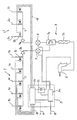
- a stock paint feed 1 has different paint supply lines 1a and a solvent feed line 1c.
- the paint supply lines 1a are not shown, in the form of pre-printed Reservoirs connected.
- the solvent feed line 1c is with a solvent reservoir, not shown connected.
- a hardener feed 2 has two hardener feed lines 2a and a solvent supply line 2c on. These lines open all in a feeder 4.
- the two hardener feeders 2a are under pre-printed, not shown Reservoirs for hardener connected, the solvent supply line 2c with a solvent reservoir, not shown.
- the preprint in the base paint feed 1 and in the hardener feed 2 can be generated by feed pumps, not shown become.
- the feeders 3 and 4 open into a mixing device 7, to which a spray device 6 is connected.
- the Mixing device 7 consists of a swirl mixer 7a and a downstream static mixer 7b.
- the base paint feed 1 and the hardener feed 2 become controlled by a control device 5, each one to be selected paint leads 1a and one of the Härterzu Oberen 2a opens and closes. This is in every paint supply line 1a and in the solvent line 1c each one provided pneumatically actuated check valve 1b.
- shut-off valves 2b In the hardener feed lines 2a and in the solvent feed line 2c are corresponding pneumatically actuated shut-off valves 2b provided.
- the check valves 1b and 2b are via compressed air lines 12th actuated by means of only schematically indicated solenoid valves 5b with a common supply line 10th are connected.
- the supply line 10 also supplies the compressed air for the spray device 6, in the illustrated embodiment a spray gun is.
- the compressed air for the Spray device 6 is provided over one of the multiple and all supplied with 5b solenoid valves.
- the amount of air to the spray device 6 is over a flow meter 5c of the total labeled 5 Supplied control device.
- the solenoid valves 5b are of a programmable logic controller 5a operated, which supplies via a cable 11 with power becomes.
- the implementation of the electrical signals in a compressed air control is because of the risk of explosion during processing of paints particularly useful.
- a check valve 3a and a Volumeter 9 is arranged in the supply 3.
- the feeder 4 has a check valve 4a and a quantity measuring device 8 on.
- the generated by the Mengenmeßvortechniken 8 and 9 Signals are sent to the programmable logic controller 5a transmitted and serve according to the in the control unit 5a for the control of the various solenoid valves 5b.
- both the amount of hardener as well as the amount of paint to the reference size and the each other size can make the controlled variable can Pressure fluctuations in both the Stammlackzu operation 1 as even in the hardener feed 2 are balanced, as well like viscosity and consistency variations of both media.
- the system remains functional, as long as one more Promotion of components is possible. That way short-term disturbances, which so far are often a shutdown required the plant without interrupting the operation overcome.
Description
Die Erfindung betrifft ein Verfahren zum Dosieren und Mischen unterschiedlicher Komponenten nach dem Oberbegriff des Patentanspruchs 1 sowie eine Vorrichtung zur Durchführung dieses Verfahrens.The invention relates to a method for dosing and mixing different components according to the generic term of claim 1 and a device for carrying out this procedure.
Bei einem bekannten Verfahren dieser Art (US 5,464,283 A) wird ein Stammlack, der die erste Komponente bildet, mit vorgegebener Menge kontinuierlich gefördert. Die Menge des kontinuierlich fließenden Lackstroms wird überwacht und die erforderliche Menge einer zweiten Komponente, nämlich von Lösungsmitteln, wird gemessen und in einem vorgegebenen Verhältnis in einen Mischer eingesetzt. Die Menge des Lösungsmittels wird über Ventile gesteuert und in einem vorgegebenen Verhältnis zur konstanten Stammlackmenge, die von einem Durchflußmesser gemessen wird. Stammlack und Lösungsmittel werden mit dem vorgegebenen festen Verhältnis gemeinsam in den Mischer eingesetzt.In a known method of this type (US 5,464,283 A) is a parent lacquer, which forms the first component, with given amount continuously promoted. The amount of continuously flowing paint stream is monitored and the required amount of a second component, namely of Solvents, measured and in a given Ratio used in a mixer. The amount of solvent is controlled by valves and in a predetermined Ratio to constant stem paint amount of a flow meter is measured. Stock varnish and solvent become common with the given fixed ratio used in the mixer.
Für die Funktionsfähigkeit des Verfahrens ist es unerläßlich, daß der Druck des Lösungsmittels stets über dem Druck des Stammlacks liegen muß. For the functioning of the process, it is essential that the pressure of the solvent is always above the pressure of the parent lacquer must be.
Bei dem bekannten Stand der Technik wird immer ein bestimmtes Differenzdruckverhältnis zwischen Stammlack und Lösungsmittel eingehalten. Die entsprechende Differenzdruckregelung dient vor allen Dingen dazu, den Lösungsmitteldruck in Abhängigkeit von dem Stammlackdruck nachzuführen. Wenn es durch irgendwelche Einflüsse, beispielsweise durch Verunreinigungen, dazu kommt, daß der Lösungsmitteldruck auf den Druck des Stammlacks oder darunter abgesinkt, muß der Austragvorgang beendet werden, weil das gewählte Mischungsverhältnis in einer solchen Betriebssituation nicht mehr eingehalten werden kann.In the known art always a certain Differential pressure ratio between base lacquer and solvent respected. The corresponding differential pressure control Above all, it serves the solvent pressure nachzuführen depending on the parent lacquer pressure. If it is influenced by any, for example Impurities, in addition, the solvent pressure has dropped to the pressure of the parent lacquer or below the discharge process will be terminated because the selected mixing ratio not in such an operating situation more can be kept.
Dem Stammlack werden nacheinander zwei Komponenten hinzugefügt, nämlich Lösungsmittel und Härter. Nachdem der Stammlack mit Lösungsmittel versetzt ist, bildet er eine neue Ausgangskomponente, die als neue erste Komponente mit vorgegebener Menge in einen zweiten Mischer eingesetzt wird. Auch die Zudosierung von Härter in den zweiten Mischer zu der aus Lösungsmittel und Stammlack bestehenden ersten Komponente kann wiederum nur in der Weise erfolgen, daß die erste Komponente aus dem ersten Mischer mit vorgegebener Menge in den zweiten Mischer eingeführt wird, während die Härtermenge in den zweiten Mischer entsprechend gesteuert bzw. geregelt zugeführt wird. Auch bei diesem zweiten Verfahrensschritt muß immer die erste Komponente konstant gefördert und die zweite Komponente nachgeführt werden. Auch hier gilt wieder, daß der Austragsvorgang beendet werden muß, wenn das gewählte Mischungsverhältnis in bestimmten Betriebssituationen nicht eingehalten werden kann, in denen der Druck des Härters unter den Druck der ersten Komponente absinkt. Two components are successively added to the stock varnish, namely solvents and hardeners. After the stem paint with solvent, it forms a new one Output component, which is a new first component with a predefined Amount is used in a second mixer. Also, the addition of hardener in the second mixer too the first component consisting of solvent and stock paint again can only be done in such a way that the first component from the first mixer with predetermined Amount introduced into the second mixer while the Volume of hardener in the second mixer controlled accordingly or regulated is supplied. Also in this second process step always the first component must be promoted constantly and the second component tracked. Also here again applies that the discharge process be terminated must, if the selected mixing ratio in certain Operating situations can not be met, in which the pressure of the hardener under the pressure of the first component decreases.
Grundsätzlich ist es auch nachteilig, daß die erforderliche Härtermenge stets in Abhängigkeit von der zugehörigen Stammlackmenge dosiert wird. Hierdurch liegt die Stammlackmenge während der überwiegenden Betriebszeit über der durch das Mischungsverhältnis vorgegebenen Härtermenge. Dieser Nachteil ist insbesondere bei kurzen Spritzintervallen störend. Er kann lediglich durch eine Dosierkontrolle mit anschließender Korrektur des Mischungsverhältnisses behoben werden.Basically, it is also disadvantageous that the required Amount of hardener always depending on the associated Stammlackmenge is dosed. This is the Stammlackmenge during the predominant operating time above the through the mixing ratio predetermined amount of hardener. This Disadvantage is disturbing especially at short injection intervals. He can only by a dosing with subsequent Correction of the mixing ratio corrected become.
Ausgehend von diesem Stand der Technik liegt der Erfindung die Aufgabe zugrunde, ein Verfahren der als bekannt vorausgesetzten Art so auszubilden, daß es weniger störanfällig und die zu seiner Durchführung erforderliche Vorrichtung funktionsfähig ist, solange die zu dosierenden Komponenten überhaupt förderbar sind, und zwar unabhängig davon, welche Drücke in den Leitungen herrschen, welche Druckunterschiede sich einstellen und welche Viskositäten die zu dosierenden Komponenten haben.Based on this prior art, the invention The task is based on a method of the assumed as known Designing a kind so that it is less prone to failure and the apparatus required for its implementation is functional as long as the components to be dosed are eligible, regardless of which Pressures in the lines prevail, which pressure differences to adjust and which viscosities are to be dosed Have components.
Die Lösung dieser Aufgabe erfolgt mit den Merkmalen des Patentanspruchs 1 bzw. mit einer Vorrichtung nach Patentanspruch 5. The solution of this object is achieved with the features of the claim 1 or with a device according to claim 5th
Bei dem erfindungsgemäßen Verfahren können die Mengen beider Komponenten über pneumatisch angesteuerte Ventile geregelt werden. Es ist ausreichend, daß die pneumatisch angesteuerten Ventile lediglich zwei Betriebszustände einnehmen können, nämlich eine Öffnungsstellung und eine Schließstellung. Dabei bleibt jedes der beiden pneumatisch angesteuerten Ventile jeweils so lange geöffnet, bis die dem gewünschten Mischungsverhältnis entsprechende vorgegebene Menge geflossen ist. Es kann so gearbeitet werden, daß das Ventil anschließend noch über eine eingestellte zusätzliche Zeit in Offenstellung bleibt. Dadurch erfolgt eine Abweichung vom vorgegebenen Mischungsverhältnis bei beiden Komponenten bzw. in Richtung sowohl eines Härterüberschusses als auch eines Härterunterschusses. Mit dem Beginn der Dosierung werden die Mengen beider Komponenten aufaddiert und entsprechend dem eingestellten Mischungsverhältnis korrigiert. Die prozentuale Abweichung der Dosiermengen vom Sollwert wird durch die wachsende Gesamtmenge ständig verringert.In the method according to the invention, the amounts of both Components controlled by pneumatically controlled valves become. It is sufficient that the pneumatically controlled Valves occupy only two operating states can, namely an open position and a closed position. In this case, each of the two pneumatically actuated remains Valves each opened as long as the desired Mixing ratio corresponding predetermined Amount has flowed. It can be worked that way Valve then still has a set additional Time in open position remains. This causes a deviation from the given mixing ratio for both components or in the direction of both a hardener excess as well as a hardening deficit. With the beginning of the dosage the amounts of both components are added up and corrected according to the set mixing ratio. The percentage deviation of dosing quantities from Setpoint is constantly reduced by the growing total.
Bevorzugte Ausgestaltungen der Erfindung ergeben sich aus den Unteransprüchen.Preferred embodiments of the invention will become apparent the dependent claims.
Nachstehend wird eine bevorzugte Ausführungsform der Erfindung anhand der Zeichnung, die eine schematische Darstellung einer Dosier- und Mischvorrichtung für Stammlacke und Härter zeigt, im einzelnen beschrieben. Below is a preferred embodiment of the invention Based on the drawing, which is a schematic representation a dosing and mixing device for masterbatches and Hardener shows, described in detail.
Eine Stammlackzuführung 1 weist verschiedene Lackzuleitungen
1a und eine Lösemittelzuleitung 1c auf. Die Lackzuleitungen
1a sind mit nicht dargestellten, unter Vordruck stehenden
Vorratsbehältern verbunden. Die Lösemittelzuleitung
1c ist mit einem nicht dargestellten Lösemittelvorratsbehälter
verbunden.A stock paint feed 1 has different
Eine Härterzuführung 2 weist zwei Härterzuleitungen 2a und
eine Lösemittelzuleitung 2c auf. Diese Leitungen münden
sämtlich in eine Zuführung 4. Die beiden Härterzuleitungen
2a sind mit unter Vordruck stehenden, nicht dargestellten
Vorratsbehältern für Härter verbunden, die Lösemittelzuleitung
2c mit einem nicht dargestellten Lösemittelvorratsbehälter.A hardener feed 2 has two
Der Vordruck in der Stammlackzuführung 1 und in der Härterzuführung 2 kann durch nicht dargestellte Förderpumpen erzeugt werden.The preprint in the base paint feed 1 and in the hardener feed 2 can be generated by feed pumps, not shown become.
Die Zuführungen 3 und 4 münden in eine Mischvorrichtung 7,
an die eine Spritzvorrichtung 6 angeschlossen ist. Die
Mischvorrichtung 7 besteht aus einem Drallmischer 7a und
einem nachgeschalteten Statikmischer 7b.The
Die Stammlackzuführung 1 und die Härterzuführung 2 werden
von einer Regelvorrichtung 5 angesteuert, die jeweils eine
der anzuwählenden Lackzuleitungen 1a und eine der Härterzuleitungen
2a öffnet und schließt. Dazu ist in jeder Lackzuleitung
1a und in der Lösemittelleitung 1c jeweils ein
pneumatisch betätigbares Sperrventil 1b vorgesehen. The base paint feed 1 and the hardener feed 2 become
controlled by a control device 5, each one
to be selected paint leads 1a and one of the Härterzuleitungen
2a opens and closes. This is in every
In den Härterzuleitungen 2a und in der Lösemittelzuleitung
2c sind entsprechende pneumatisch betätigbare Sperrventile
2b vorgesehen.In the
Die Sperrventile 1b und 2b sind über Druckluftleitungen 12
betätigbar, die mittels nur schematisch angedeuteter Magnetventile
5b mit einer gemeinsamen Versorgungsleitung 10
verbunden sind.The
Die Versorgungsleitung 10 liefert auch die Druckluft für
die Spritzvorrichtung 6, die im dargestellten Ausführungsbeispiel
eine Spritzpistole ist. Die Druckluft für die
Spritzvorrichtung 6 wird über eines der mehrfach vorgesehenen
und sämtlich mit 5b bezeichneten Magnetventile zugeführt.
Die Luftmenge zur Spritzvorrichtung 6 wird über
einen Durchflußmesser 5c der insgesamt mit 5 bezeichneten
Regelvorrichtung zugeführt. Die Magnetventile 5b werden von
einer speicherprogrammierbaren, elektronischen Steuereinheit
5a betätigt, die über ein Kabel 11 mit Strom versorgt
wird. Die Umsetzung der elektrischen Signale in eine Druckluftsteuerung
ist wegen der Explosionsgefahr bei der Verarbeitung
von Lacken besonders sinnvoll.The
In der Zuführung 3 sind ein Rückschlagventil 3a und eine
Mengenmeßvorrichtung 9 angeordnet. Die Zuführung 4 weist
ein Rückschlagventil 4a und eine Mengenmeßvorrichtung 8
auf. Die von den Mengenmeßvorrichtungen 8 und 9 erzeugten
Signale werden auf die speicherprogrammierbare Steuereinheit
5a übertragen und dienen entsprechend dem in der Steuereinheit
5a niedergelegten Programm zur Ansteuerung der
verschiedenen Magnetventile 5b. In the supply 3, a check valve 3a and a
Nach dem Betätigen der Spritzvorrichtung 6, beispielsweise
durch Ziehen eines Abzugshebels, wird die angewählte Lackzuleitung
1a durch das zugehörige Sperrventil 1b geöffnet,
so daß eine durch die Regelvorrichtung 5 vorgegebene Lackmenge
durch die Zuführung 3 strömt. Die pro Zeitintervall
geförderte Lackmenge wird durch die Mengenmeßvorrichtung 9
gemessen. Das zur Steuereinheit 5a übertragene Signal der
Mengenmeßvorrichtung 9 veranlaßt die Steuerung dazu, das
Sperrventil 2b der angewählten Härterleitung 2a zu öffnen,
so daß dem in die Mischvorrichtung 7 einströmenden Lack eine
dem vorgebenen Verhältnis von Lack zu Härter entsprechende
Härtermenge hinzugefügt wird. Sobald durch die Mengenmeßvorrichtung
8 ein Härterüberschuß festgestellt wird,
schließt die Regelvorrichtung 5 das Ventil 2b so lange, bis
wegen der anschließend ausschließlich zuströmenden
Lackmenge wieder Härter benötigt und angefordert wird. Auf
diese Weise wird in der Mischvorrichtung das gewünschte Mischungsverhältnis
exakt gebildet.After pressing the spray device 6, for example
by pulling a trigger, the selected
Wenn infolge von Störungen, wie sie sich beispielsweise
durch Viskositätsschwankungen, kurzfristige Verschmutzungen
oder dergleichen ergeben, das mit dem kontinuierlich zugeführtem
Lack zu bildende Mischungsverhältnis trotz eines
ständig geöffneten Sperrventils 2b nicht eingehalten werden
kann, wird die Lackzufuhr durch das Schließen des vorher
geöffneten Ventils 1b so lange unterbrochen, bis eine ausreichende
Härtermenge zugeströmt ist. In diesem Fall wird
also die Menge des geförderten Lacks der Menge des geförderten
Härters nachgeführt. Im Gegensatz zu dem vorher beschriebenen
Betriebszustand wird dann also das durch die
Mengenmeßvorrichtung 8 ermittelte Signal für die Härtermenge
zur Führungsgröße, dem die Lackmenge als Regelgröße
folgt. Wegen dieses Funktionsprinzips, das sowohl die Härtermenge
als auch die Lackmenge zur Führungsgröße und die
jeweils andere Größe zur Regelgröße machen kann, können
Druckschwankungen sowohl in der Stammlackzuführung 1 als
auch in der Härterzuführung 2 ausgeglichen werden, ebenso
wie Viskositäts- und Konsistenzschwankungen beider Medien.
Die Anlage bleibt also funktionsfähig, solange noch eine
Förderung der Komponenten möglich ist. Auf diese Weise werden
kurzfristige Störungen, die bisher häufig ein Abfahren
der Anlage erforderlich machten, ohne Unterbrechung des Betriebs
überwunden.When, as a result of disturbances, such as, for example
due to viscosity fluctuations, short-term soiling
or the like, with the continuously supplied
Lack to be formed mixing ratio despite one
constantly open shut-off
Claims (12)
- Method of dosing and mixing different components, in particular base paint and hardener, and dispensing by means of a spraying device (6), with a first component under pre-pressure, a second component under pre-pressure and solvent for the first component under pre-pressure, wherein components flowing through valves are recorded by means of quantity measuring devices (8; 9), are firstly fed to a mixing device (7) and subsequently to the spraying device (6) wherein one component is fed with the pre-specified quantity and the quantity of the other component is fed in a controlled way depending upon the quantity of the one component through controlling the opening time of a locking valve (1b; 2b),
characterised in that
optionally the first or the second component is controlled and the other one is fed with the pre-specified quantity. - Method according to claim 1
characterised in that
the quantity of the two supplied components is continuously measured, added up and continuously compared with the prescribed indications. - Method according to claim 1 or 2
characterised in that
the two components can be dosed with a pre-specified time lag exceeding the exact dosing time corresponding to the pre-specified quantity. - Method according to one or several of the claims 1 to 3
characterised in that
a change of the components from guide value into control value takes place as soon as the quantity of the supplied components runs continuously. - Device for carrying out the method according to claim 1 with at least two supply lines under feed pressure for two components, two quantity measuring devices (8; 9), with a mixing device (7), into which the two components are introduced and a regulating device (5) which in accordance with a pre-specified mixing ratio regulates the quantities of a component by means of a locking valve (2b) depending upon the measured quantity of the other component
characterised in that
the regulating device (5) is formed for the purpose of regulating also the quantity of the other component depending upon the measured quantity of one component and regulates a further locking valve (1b) for the other component. - Device according to claim 5
characterised in that
the feeders (3; 4) both of the first component and of the second component are each connected to a solvent supply line (1c; 2c). - Device according to claim 5 or 6
characterised in that
the locking valves (1b; 2b) can be activated by compressed air. - Device according to one or several of the claims 5 to 7
characterised in that
the spraying device (6) is connected to a compressed air line and the trigger device is formed for initiating output of compressed air before the beginning of the mix delivery. - Device according to claim 8
characterised in that
in the compressed air line a quantity measuring device is arranged whose signals are fed to a stored program control unit (5a) of the regulating device (5). - Device according to one or several of the claims 5 to 9
characterised in that
the compressed air for the locking valves (1b 2b) can be controlled through magnetic valves (5b) controlled by the regulating device (5). - Device according to one or several of the claims 5 to 10
characterised in that
a non-return valve (3a; 4a) is provided in each feeder (3; 4) to the mixing device (7). - Device according to one or several of the claims 5 to 11
characterised in that
the quantity measuring device (8; 9) is a flow measuring device.
Applications Claiming Priority (3)
| Application Number | Priority Date | Filing Date | Title |
|---|---|---|---|
| DE19848640A DE19848640C2 (en) | 1998-10-22 | 1998-10-22 | Method and device for dosing and mixing different components |
| DE19848640 | 1998-10-22 | ||
| PCT/EP1999/007586 WO2000024522A1 (en) | 1998-10-22 | 1999-10-09 | Method and device for dosing and mixing different components |
Publications (2)
| Publication Number | Publication Date |
|---|---|
| EP1123163A1 EP1123163A1 (en) | 2001-08-16 |
| EP1123163B1 true EP1123163B1 (en) | 2003-07-23 |
Family
ID=7885245
Family Applications (1)
| Application Number | Title | Priority Date | Filing Date |
|---|---|---|---|
| EP99950687A Expired - Lifetime EP1123163B1 (en) | 1998-10-22 | 1999-10-09 | Method and device for dosing and mixing different components |
Country Status (7)
| Country | Link |
|---|---|
| US (1) | US6543647B1 (en) |
| EP (1) | EP1123163B1 (en) |
| JP (1) | JP4383669B2 (en) |
| KR (1) | KR100558103B1 (en) |
| DE (2) | DE19848640C2 (en) |
| ES (1) | ES2204160T3 (en) |
| WO (1) | WO2000024522A1 (en) |
Families Citing this family (12)
| Publication number | Priority date | Publication date | Assignee | Title |
|---|---|---|---|---|
| FR2809970B1 (en) * | 2000-06-08 | 2003-09-05 | Eisenmann France Sarl | METHOD FOR PRODUCING AND APPLYING MULTI-COMPONENT PAINT BY SPRAYING |
| DE10121950B4 (en) * | 2001-05-05 | 2014-10-09 | Wolfgang Schmidt | Device for producing a multi-component mixture |
| US8851111B2 (en) † | 2001-11-27 | 2014-10-07 | Graco Inc. | Electronic proportioner using continuous metering and correction |
| KR100818369B1 (en) * | 2007-03-29 | 2008-04-02 | 사단법인 한국가속기 및 플라즈마 연구협회 | Manufacturing apparatus for making mixture capsule of metal powder and oxidizer powder |
| US8224481B2 (en) * | 2009-01-19 | 2012-07-17 | Access Business Group International Llc | Method and apparatus for dispensing fluid compositions |
| DE102009032484A1 (en) * | 2009-07-09 | 2011-01-13 | Marco Systemanalyse Und Entwicklung Gmbh | Mixing device for dosing and mixing of multi-component media, has media channels, each of which in each case is closed by dosing valve, where single static mixing tube is provided with both media channels |
| DE102012010544B4 (en) * | 2012-05-29 | 2017-02-09 | J. Wagner Ag | Method and apparatus for mixing at least two liquid components |
| CN107787251B (en) | 2015-02-05 | 2020-01-10 | 卡莱流体技术有限公司 | Spray tool system |
| US10324428B2 (en) | 2015-02-12 | 2019-06-18 | Carlisle Fluid Technologies, Inc. | Intra-shop connectivity system |
| US11273462B2 (en) | 2015-11-26 | 2022-03-15 | Carlisle Fluid Technologies, Inc. | Sprayer system |
| US10434525B1 (en) * | 2016-02-09 | 2019-10-08 | Steven C. Cooper | Electrostatic liquid sprayer usage tracking and certification status control system |
| CN114570582A (en) * | 2022-03-04 | 2022-06-03 | 山东中清智能科技股份有限公司 | Paint supply, recovery and cleaning integrated device |
Family Cites Families (7)
| Publication number | Priority date | Publication date | Assignee | Title |
|---|---|---|---|---|
| US3201048A (en) * | 1963-04-19 | 1965-08-17 | Gen Motors Corp | Multiple fluid spray gun with remotely operable selective valve control |
| US3802605A (en) * | 1971-10-08 | 1974-04-09 | Ciba Geigy Corp | Flow compensating metering unit |
| US4131395A (en) * | 1976-09-29 | 1978-12-26 | Gusmer Corporation | Feeder for apparatus for ejecting a mixture of a plurality of liquids |
| US4285446A (en) * | 1979-06-22 | 1981-08-25 | Ransburg Corporation | Automatic purging system having a pressure sensor and a timing mechanism |
| US5407267A (en) * | 1992-12-30 | 1995-04-18 | Nordson Corporation | Method and apparatus for forming and dispensing coating material containing multiple components |
| DE4332125A1 (en) * | 1993-09-22 | 1995-03-23 | Wagner Wilhelm Wiwa | Method for mixing material components and device for carrying out the method |
| JPH09314031A (en) * | 1996-05-30 | 1997-12-09 | Honda Motor Co Ltd | Cleaning method for coating device |
-
1998
- 1998-10-22 DE DE19848640A patent/DE19848640C2/en not_active Expired - Fee Related
-
1999
- 1999-10-09 JP JP2000578118A patent/JP4383669B2/en not_active Expired - Fee Related
- 1999-10-09 EP EP99950687A patent/EP1123163B1/en not_active Expired - Lifetime
- 1999-10-09 KR KR1020017002204A patent/KR100558103B1/en not_active IP Right Cessation
- 1999-10-09 WO PCT/EP1999/007586 patent/WO2000024522A1/en active IP Right Grant
- 1999-10-09 ES ES99950687T patent/ES2204160T3/en not_active Expired - Lifetime
- 1999-10-09 DE DE59906381T patent/DE59906381D1/en not_active Expired - Lifetime
- 1999-10-10 US US09/807,849 patent/US6543647B1/en not_active Expired - Lifetime
Also Published As
| Publication number | Publication date |
|---|---|
| EP1123163A1 (en) | 2001-08-16 |
| US6543647B1 (en) | 2003-04-08 |
| DE59906381D1 (en) | 2003-08-28 |
| ES2204160T3 (en) | 2004-04-16 |
| WO2000024522A1 (en) | 2000-05-04 |
| JP2002528251A (en) | 2002-09-03 |
| DE19848640A1 (en) | 2000-05-25 |
| JP4383669B2 (en) | 2009-12-16 |
| DE19848640C2 (en) | 2000-10-19 |
| KR100558103B1 (en) | 2006-03-10 |
| KR20010072826A (en) | 2001-07-31 |
Similar Documents
| Publication | Publication Date | Title |
|---|---|---|
| EP0412289B1 (en) | Electrostatic spray device | |
| DE102012010544B4 (en) | Method and apparatus for mixing at least two liquid components | |
| EP1123163B1 (en) | Method and device for dosing and mixing different components | |
| EP0003224B1 (en) | Apparatus for metering at least one component of a mixed liquid | |
| EP1104334B1 (en) | Powder spray coating device | |
| EP0347607A2 (en) | Method and device for leading a product to be sprayed to a plurality of spraying stations | |
| DE19808765A1 (en) | Powder coating system and method for feeding and mixing powder in a coating system | |
| DE4302165C1 (en) | Fat content control for milk and cream - by measuring density of milk and cream from sepg. centrifuge to add fat-free milk to cream as required to adjust its fat content | |
| DE102009060454B4 (en) | Device for aerosol production | |
| EP0763385B1 (en) | Method for transporting a powdry material by means of an injection | |
| DE19838279A1 (en) | Powder coating system has an injector stage with air supply controlled by restrictor valves that are coupled to a processor | |
| CH688989A5 (en) | Apparatus for conveying powder | |
| DE2733102A1 (en) | METHOD AND DEVICE FOR ATOMIZING LIQUIDS | |
| DE102008031005B3 (en) | Gas flow producing method for calibrating flow rate measuring device, involves actuating branch-off valve such that rear nozzle-input pressure is changed to rear nozzle-input-set pressure that adjusts gas flow with mass flow in branch line | |
| DE10111891A1 (en) | Powder spraying device for coating powder | |
| DE3430953C2 (en) | ||
| EP0357929A2 (en) | Mehtod and device to gauge setting accelerators during application of shotcrete | |
| EP1384503A2 (en) | Process and apparatus for dosing and mixing pumpable components and lance for extracting the components from a container | |
| DE10008389A1 (en) | Influencing drop spectrum of suspensions comprises adjusting splitting ratio of partial streams divided by nozzles, and adjusting average diameter of drops using valve or pump | |
| EP1764159B1 (en) | Coating device and method | |
| DE3501127C2 (en) | ||
| EP0179189A2 (en) | Method and device for proportioning and mixing two liquids | |
| DE202009017542U1 (en) | Device for aerosol production | |
| DD150984A3 (en) | DISTILLATION APPARATUS WITH REGULATED COOLING WATER RUNNING AND DISTILLATED VOLUME THEREFOR | |
| DE10125863A1 (en) | Commercial gas flow production involves taking mixed gas from buffer, and compensating for deviations in flow from surplus gas flow, to maintain constant mixture ratio |
Legal Events
| Date | Code | Title | Description |
|---|---|---|---|
| PUAI | Public reference made under article 153(3) epc to a published international application that has entered the european phase |
Free format text: ORIGINAL CODE: 0009012 |
|
| 17P | Request for examination filed |
Effective date: 20001128 |
|
| AK | Designated contracting states |
Kind code of ref document: A1 Designated state(s): AT BE CH CY DE DK ES FI FR GB GR IE IT LI LU MC NL PT SE |
|
| GRAH | Despatch of communication of intention to grant a patent |
Free format text: ORIGINAL CODE: EPIDOS IGRA |
|
| GRAH | Despatch of communication of intention to grant a patent |
Free format text: ORIGINAL CODE: EPIDOS IGRA |
|
| GRAA | (expected) grant |
Free format text: ORIGINAL CODE: 0009210 |
|
| AK | Designated contracting states |
Designated state(s): DE ES FR GB IT |
|
| REG | Reference to a national code |
Ref country code: GB Ref legal event code: FG4D Free format text: NOT ENGLISH |
|
| GBT | Gb: translation of ep patent filed (gb section 77(6)(a)/1977) |
Effective date: 20030723 |
|
| REG | Reference to a national code |
Ref country code: IE Ref legal event code: FG4D Free format text: GERMAN |
|
| REF | Corresponds to: |
Ref document number: 59906381 Country of ref document: DE Date of ref document: 20030828 Kind code of ref document: P |
|
| REG | Reference to a national code |
Ref country code: GB Ref legal event code: 732E |
|
| RAP2 | Party data changed (patent owner data changed or rights of a patent transferred) |
Owner name: GRACO GESELLSCHAFT MIT BESCHRAENKTER HAFTUNG |
|
| REG | Reference to a national code |
Ref country code: IE Ref legal event code: FD4D |
|
| REG | Reference to a national code |
Ref country code: ES Ref legal event code: FG2A Ref document number: 2204160 Country of ref document: ES Kind code of ref document: T3 |
|
| ET | Fr: translation filed | ||
| REG | Reference to a national code |
Ref country code: FR Ref legal event code: TP |
|
| PLBE | No opposition filed within time limit |
Free format text: ORIGINAL CODE: 0009261 |
|
| STAA | Information on the status of an ep patent application or granted ep patent |
Free format text: STATUS: NO OPPOSITION FILED WITHIN TIME LIMIT |
|
| 26N | No opposition filed |
Effective date: 20040426 |
|
| PGFP | Annual fee paid to national office [announced via postgrant information from national office to epo] |
Ref country code: ES Payment date: 20071120 Year of fee payment: 9 |
|
| PGFP | Annual fee paid to national office [announced via postgrant information from national office to epo] |
Ref country code: IT Payment date: 20071026 Year of fee payment: 9 |
|
| REG | Reference to a national code |
Ref country code: FR Ref legal event code: ST Effective date: 20090630 |
|
| PG25 | Lapsed in a contracting state [announced via postgrant information from national office to epo] |
Ref country code: IT Free format text: LAPSE BECAUSE OF NON-PAYMENT OF DUE FEES Effective date: 20081009 |
|
| REG | Reference to a national code |
Ref country code: FR Ref legal event code: RN |
|
| PG25 | Lapsed in a contracting state [announced via postgrant information from national office to epo] |
Ref country code: FR Free format text: LAPSE BECAUSE OF NON-PAYMENT OF DUE FEES Effective date: 20081031 |
|
| REG | Reference to a national code |
Ref country code: FR Ref legal event code: FC |
|
| REG | Reference to a national code |
Ref country code: ES Ref legal event code: FD2A Effective date: 20081010 |
|
| PG25 | Lapsed in a contracting state [announced via postgrant information from national office to epo] |
Ref country code: ES Free format text: LAPSE BECAUSE OF NON-PAYMENT OF DUE FEES Effective date: 20081010 |
|
| PGRI | Patent reinstated in contracting state [announced from national office to epo] |
Ref country code: FR Effective date: 20091215 |
|
| REG | Reference to a national code |
Ref country code: FR Ref legal event code: PLFP Year of fee payment: 17 |
|
| REG | Reference to a national code |
Ref country code: FR Ref legal event code: PLFP Year of fee payment: 18 |
|
| REG | Reference to a national code |
Ref country code: FR Ref legal event code: PLFP Year of fee payment: 19 |
|
| PGFP | Annual fee paid to national office [announced via postgrant information from national office to epo] |
Ref country code: DE Payment date: 20171027 Year of fee payment: 19 Ref country code: FR Payment date: 20171025 Year of fee payment: 19 |
|
| PGFP | Annual fee paid to national office [announced via postgrant information from national office to epo] |
Ref country code: GB Payment date: 20171027 Year of fee payment: 19 |
|
| REG | Reference to a national code |
Ref country code: DE Ref legal event code: R119 Ref document number: 59906381 Country of ref document: DE |
|
| GBPC | Gb: european patent ceased through non-payment of renewal fee |
Effective date: 20181009 |
|
| PG25 | Lapsed in a contracting state [announced via postgrant information from national office to epo] |
Ref country code: DE Free format text: LAPSE BECAUSE OF NON-PAYMENT OF DUE FEES Effective date: 20190501 |
|
| PG25 | Lapsed in a contracting state [announced via postgrant information from national office to epo] |
Ref country code: FR Free format text: LAPSE BECAUSE OF NON-PAYMENT OF DUE FEES Effective date: 20181031 |
|
| PG25 | Lapsed in a contracting state [announced via postgrant information from national office to epo] |
Ref country code: GB Free format text: LAPSE BECAUSE OF NON-PAYMENT OF DUE FEES Effective date: 20181009 |