EP1122878A2 - Piezoelectric driving body for ultrasonic motors - Google Patents
Piezoelectric driving body for ultrasonic motors Download PDFInfo
- Publication number
- EP1122878A2 EP1122878A2 EP01300799A EP01300799A EP1122878A2 EP 1122878 A2 EP1122878 A2 EP 1122878A2 EP 01300799 A EP01300799 A EP 01300799A EP 01300799 A EP01300799 A EP 01300799A EP 1122878 A2 EP1122878 A2 EP 1122878A2
- Authority
- EP
- European Patent Office
- Prior art keywords
- vibrating body
- ultrasonic motor
- piezoelectric element
- center
- electrodes
- Prior art date
- Legal status (The legal status is an assumption and is not a legal conclusion. Google has not performed a legal analysis and makes no representation as to the accuracy of the status listed.)
- Granted
Links
Images


Classifications
-
- H—ELECTRICITY
- H02—GENERATION; CONVERSION OR DISTRIBUTION OF ELECTRIC POWER
- H02N—ELECTRIC MACHINES NOT OTHERWISE PROVIDED FOR
- H02N2/00—Electric machines in general using piezoelectric effect, electrostriction or magnetostriction
- H02N2/0005—Electric machines in general using piezoelectric effect, electrostriction or magnetostriction producing non-specific motion; Details common to machines covered by H02N2/02 - H02N2/16
- H02N2/001—Driving devices, e.g. vibrators
- H02N2/0015—Driving devices, e.g. vibrators using only bending modes
-
- H—ELECTRICITY
- H02—GENERATION; CONVERSION OR DISTRIBUTION OF ELECTRIC POWER
- H02N—ELECTRIC MACHINES NOT OTHERWISE PROVIDED FOR
- H02N2/00—Electric machines in general using piezoelectric effect, electrostriction or magnetostriction
- H02N2/10—Electric machines in general using piezoelectric effect, electrostriction or magnetostriction producing rotary motion, e.g. rotary motors
- H02N2/103—Electric machines in general using piezoelectric effect, electrostriction or magnetostriction producing rotary motion, e.g. rotary motors by pressing one or more vibrators against the rotor
Definitions
- the present invention relates to a piezoelectric driving body and an-ultrasonic motor having a piezoelectric element as a driving source, and to an electronic apparatus such as an electronic timepiece, a medical equipment, an optical information apparatus, a camera and the like.
- the conventional ultrasonic motors as disclosed in Japanese Patent Publication No. 7750/1994 utilize deflection-vibration in a circumferential direction of the vibrating body, the vibrating body must have been increased in plate thickness in order to obtain displacement in a feed direction of the moving body, i.e. displacement in a circumferential direction, thus incurring increase in resonant frequency.
- the resonant frequency has been increased with increase in the number of waves in the circumferential direction and the number of nodes with respect to a radial direction.
- the thickness of the ultrasonic motor has been increased.
- the increase of manufacture cost has been incurred due to forming one by one vibrating bodies by machining.
- the present invention realizes an ultrasonic motor capable of suppressing in crease in resonant frequency and obtaining a great amplitude even if made smaller, and it is an object to provide an excellent-quality ultrasonic motor that is simple in manufacturing method and mass-producible at one time, and an electronic apparatus using same.
- an ultrasonic motor of the present invention is characterized, in an ultrasonic motor having a vibrating body in a quadrilateral plate form, a piezoelectric element bonded on the vibrating body, a protrusion provided on the vibrating body, and a moving body in contact with the protrusion to be driven by same, in that the piezoelectric element oscillates a vibration wave having a node on a diagonal line of the vibrating body or on lines with which the vibrating body is divided into two and four, and the protrusion being provided in a position off the node.
- the node of vibration to be oscillated by the vibrating body can be moved to vary a direction of rotation of the moving body.
- the vibrating body is quadrilateral in shape, a multiplicity of vibrating bodies can be formed at one time by dicing or the like. Even if blanking is made using a press or the like, material can be effectively utilized without leaving the remainder.
- the polarizing directions of the piezoelectric element having a plurality of electrode portions are all made in the same direction. Due to this, for example, it is possible to suppress or make even deformation caused where polarization is made after the piezoelectric element is bonded to the vibrating body. The contact situation with the moving body contacting the vibrating body becomes favorable. By polarizing the entire piezoelectric element in the same direction at one time, polarization is favorably provided without impeding required deformation of the piezoelectric element during polarization, and thus making it possible to obtain a large drive force from the piezoelectric vibrating body.
- Fig. 1 shows a plan view and side view of an ultrasonic motor 100 of the present invention.
- Fig. 2 is a top view of the ultrasonic motor 100 removed of a moving body 8.
- a square vibrating body 1 is joined with a piezoelectric element 2.
- the vibrating body 1 at its center is fixed, for example by driving-in, by a center shaft 5 fixed to a support plate 4.
- steps 6a of a pressure-applying body 6 are engaged to restrict the moving body 8 from moving in a surface inward direction.
- the pressure-applying body 6 at a center hole 6a is guided by the center shaft 5 and rotates together with the moving body 8.
- In the hole 6a may be provided a material high in wear resistance and having a low frictional coefficient, e.g. an engineering-plastic-made bush, an oil-immersion bearing, a ceramics bearing or the like. It may be also provided with a ball bearing.
- the pressure-applying body 6 at the center is deflected by a fixing body 7 fixed on the center shaft 5, to provide a contact pressure between the moving body 8 and protrusions 1a provided on the vibrating body 1.
- protrusions 1a of two in number are provided on the vibrating body 1 in point-symmetric positions about the center shaft 5.
- the protrusions 1a are each provided along a side of the vibrating body 1 at a center point thereof.
- the vibrating body 1 is bonded with a piezoelectric body 2 by which a standing wave is oscillated with a node on one diagonal line 10a.
- the protrusion 1a at a tip rising in a center-shaft direction also displaces in a direction of the arrow 11a, 11b (in a direction perpendicular to the diagonal line 10a). Consequently, the moving body 8 rotates in a direction of the arrow 12.
- the protrusions 1a in principle, may be provided anywhere provided that they are in positions off the four corners, and the protrusions 1a may be one in number.
- the piezoelectric element 2 has, on one surface, four electrodes 3b, 3c, 3d, 3e in areas divided in a grating form by connecting between center points of the mutually-parallel sides of the vibrating body 1.
- the piezoelectric element 2 has an electrode 3a extending over the entire of the other surface thereof, and in the entire portion is polarization-treated in the same direction as a thickness direction.
- + refers to a polarization direction.
- a drive electrode is applied between the electrode 3a and the electrode 3b, 3e, a standing wave is caused having a node on the diagonal line 10b of Fig. 2.
- a drive signal is applied between the electrode 3a and the electrode 3c, 3d, a standing wave is caused having a node on a diagonal line 10a of Fig. 2.
- the piezoelectric element has, on one surface, four electrode parts 3f, 3g, 3h, 3i in the areas of the vibrating body 1 divided in triangular forms by two diagonal lines, and polarization-treated in the same direction as the thickness direction in the entire portion.
- the piezoelectric element 2 has an electrode 3a provided over the entire surface thereof.
- a standing wave having a node on the diagonal line 10a of Fig. 2 is caused.
- a driving signal between the electrode 3a and the electrode 3f, 3i or the electrode 3a and the electrode 3g, 3h a standing wave having a node on the diagonal line 10b of Fig. 2 is caused.
- Fig. 5 is an example that protrusions 1a are extended toward the outside of the vibrating body 1.
- the moving body 8 makes contact solely with the protrusions 1a of the vibrating body 1, the protrusions 1a may be made flush with the vibrating body 1.
- the vibrating body 1 can be manufactured at one time by a process, such as of etching, reducing the thickness of the ultrasonic motor 100.
- Fig. 6 is an example that the protrusions 1a are in deviated positions.
- the protrusions are provided two in number, wherein provided equal are a distance of from a first protrusion to a first corner and a distance from a second protrusion to a second corner diagonally positioned to the first corner.
- Fig. 7 is an example that the protrusions 1a are shifted to a side of smaller vibration amplitude. Also in this case, it is possible to suppress the vibration amplitude from decreasing due to application pressure.
- vibration mode having one node was used herein, a vibration mode having a plurality of nodes parallel with this node may be utilized. Also, a vibration mode having a node circle may be utilized.
- Fig. 8 is a top view of the ultrasonic motor 100 of Fig. 1 removed of the moving body 8.
- the vibrating body 1 oscillates a vibration wave having a node 10c, by the piezoelectric element 2, on a line connecting between a center of a first side of the vibrating body 1 and a center of a second side opposed to the first side.
- the protrusions 1a are provided in positions off the node, e.g. on a diagonal line of the vibrating body. At this time, the protrusion 1a rising in a center-shaft direction displaces also in a direction of the arrow 11e, 11f (in a direction perpendicular to a diagonal line 10c). Accordingly, the moving body 3 rotates in a direction of the arrow 13. On the other hand, if a standing wave having a node of 10d is oscillated, the tip of the protrusion 1a displaces in a direction of the arrow 11g, 11h (in a perpendicular direction to a diagonal line 10d). Accordingly, the moving body 3 rotates in a direction of the arrow 12 reverse to the arrow 13.
- the ultrasonic motor 100 becomes constant in output characteristic regardless of rotational direction of the moving body 8.
- the protrusions 1a may be provided anywhere provided that they are in positions off the node, and the protrusion 1a may be one in number.
- the electrode structure of the piezoelectric element 2 used in this embodiment may be in the form shown in Fig. 3.
- a drive signal is applied between the electrode 3a and the electrode 3b, 3d or 3c, 3e
- a standing wave having a node on the diagonal line 10c is caused.
- a drive signal is applied between the electrode 3a and the electrode 3b, 3c or 3d, 3e
- a standing wave having a node on the diagonal line 10d is caused.
- the electrode structure of the piezoelectric element 2 may use the one shown in Fig. 4. In such a case, a vibration wave is oscillated on the vibrating body 1 by applying a drive signal between adjacent two electrodes of the four electrodes 3f, 3g, 3h, 3i in the figure.
- a standing wave having a node on the diagonal line 10c is caused.
- a drive signal between the electrode 3a and the electrode 3g, 3i is caused.
- vibration mode having one node was used herein, a vibration mode having a plurality of nodes parallel with this node may be utilized. Also, a vibration mode having a node circle may be utilized.
- a standing wave A is oscillated having nodes 10c' and 10c" parallel with the node 10c, besides the node 10c (although the nodes are shown by a straight line, it in actual may have a curve line).
- the higher-order vibration mode having a plurality of nodes is high in electric-mechanic coupling coefficient and can obtain high output at low voltage.
- the protrusion 1a positioned off the node and belly of vibration displaces in also the direction of the arrow 11i, 11j during rising. Accordingly, the moving body 8 rotates in a direction of the arrow 12.
- the electrode structure of the piezoelectric element 2 used for driving may be the one shown in Fig. 3.
- a driving signal is applied between the electrode 3a and the electrode 3b, 3c or the electrode 3a and the electrode 3d, 3e
- a standing wave is oscillated having nodes 10c, 10c', 10c.
- a driving signal is applied between the electrode 3a and the electrode 3c, 3e or the electrode 3a and the electrode 3b, 3d
- a standing wave is oscillated having nodes 10d, 10d', 10d".
- the vibrating body 1 herein used a square form, it may be in a rectangular form or a form having a curve surface.
- the form of the vibrating body 1 is arbitrary provided that oscillation can be made in a mode as shown in the above and an ultrasonic motor 100 can be structured.
- Fig. 11 is a top view of the ultrasonic motor 100 of Fig. 1 removed of the moving body 3.
- the vibrating body oscillates, by the piezoelectric element 2, a vibration wave having nodes 10c and 10d on a line connecting between a center of a first side of the vibrating body 1 and a center of a second side opposed to the first side and a line connecting between a center of a third side and a center of a fourth side opposed to the third side.
- the protrusions 1a are provided in positions off the node and belly. In the case that the protrusions 1a are provided as in Fig. 11, the tip of the protrusion 1a rises in a center shaft direction and displaces also in a direction of the arrow 11m, 11n. Accordingly, the moving body 8 rotates in a direction of the arrow 13.
- the protrusions 1a in principle may be anywhere provided that they are off the node and diagonal line. Also, the protrusions 1a may be one in number or four in each node.
- the electrode structure of the piezoelectric element 2 may use the same as Fig. 3.
- a drive signal may be applied to the electrodes in the diagonal, i.e. between the electrode 3a and the electrode 3b, 3e or between the electrode 3a and the electrode 3c, 3d.
- drive signals different in phase by 180 degrees may be applied between the electrode 3a and the electrode 3b, 3d and between the electrodes 3a and 3c, 3e.
- a vibration wave having nodes 10c and 10d is oscillated on a line connecting between a center of a first side of the vibrating body 1 and a center of a second side opposed to the first side and a line connecting between a center of a third side and a center of a fourth side opposed to the third side.
- the points in a diagonal e.g. the electrodes 3b and 3e and the electrodes 3c and 3d are provided as respective sets and the two sets are given reverse in polarizing direction, the phases of the drive signals applied to the electrodes may be the same.
- the ultrasonic motor 100 is increased in output.
- a drive signal may be applied only to two opposed electrodes 3i, 3g or 3f, 3h.
- a vibration mode having a node circle as a higher mode than the above vibration mode may be utilized.
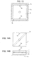
- Fig. 13 is an example of supporting two corners 1b on one diagonal line of the vibrating body 1 shown in Embodiment 2.
- the vibrating body 1 is divided with an oscillating portion having protrusions 1a and a fixed portion 1c (hatched portion in Fig. 13) that are joined through two corners 1b on the diagonal line.
- forming is possible at one time by etching including the support portion 1b and fixed portion 1c of the vibrating body 1.
- one diagonal line is restricted, it is possible to prevent other unwanted vibration modes from occurring.
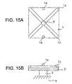
- Fig. 14 is an example that one diagonal line of the vibrating body is fixed by a fixing body 14.
- Fig. 14A is a top view and Fig. 14B is a side view.
- the vibrating body 1 is fixed to the support plate 4 through the fixing body 14. Bonding may be made by adhesive, solder or the like between the vibrating body 1 and the fixing body 14 or between the fixing body 14 and the support plate 4. Otherwise, the both may be integrally fabricated. This prevents other unwanted vibration modes from occurring and provides a strong structure against application pressure from the pressure-applying body 6, thus enabling generation of high torque. In supporting the vibrating body 1 of Embodiment 3, it is satisfactory to similarly support it on a line having nodes.
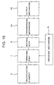
- Fig. 15 is an example that in the vibrating body of Embodiment 1 a groove is provided on the diagonal lines of the vibrating body 1, i.e. in a position of vibration node, wherein Fig. 15A is a top view and Fig. 15B is a side view.
- Fig. 15A is a top view
- Fig. 15B is a side view.
- a groove 1c may be provided on a line having nodes. Also, regardless of the groove, a similar effect can be obtained if means for reducing rigidity is provided by means of a hole or the like in part on the node.
- a thin, thick film comprising a piezoelectric element 2 by using a process of a sputter method, a sol-gel method, a printing method, an ion beam method, a molecular beam epitaxy method, a laser ablation method, a gas deposition method, an electrophretic method, an (MO)CVD method or the like, without using an adhesive.
- strain is caused during polarization, if polarization treatment is made in different directions in a same plane, strain differs in direction causing complicated deformation in the vibrating body 1 bonded with the piezoelectric element 2. Due to this, the contact between the vibrating body 1 and the piezoelectric body 2 becomes uneven thus causing lowering in motor characteristics.
- the electrode 3a is not necessarily needed. If the vibrating body 1 is a conductor, the vibrating body 1 can serve also-as an electrode of the piezoelectric element 2.
- the electrode 3 form, the vibrating body 1 form and the like are not limited to those shown in the drawings but may be anything provided that the piezoelectric driver has a piezoelectric element 2 having a plurality of electrodes. Accordingly, an actuator, sensor, transformer, filter having a piezoelectric element 2 and the like are included in a category of the present embodiment.
- Fig. 16 shows a block diagram of Embodiment 7 that the invention is applied to an electronic apparatus having an ultrasonic motor.
- An electronic apparatus 200 having an ultrasonic motor is realized by comprising a vibrating body 1 bonded with a piezoelectric element 2 processed by a predetermined polarization treatment, a moving body 8 to be driven by the vibrating body 1, a pressure-applying body 6 to pressure-contact between the vibrating body 1 and the moving body 8 to be driven by the vibrating body 1, a transmission mechanism 14 to operate by interaction with the moving body 8, and an output mechanism 15 to move based on operation of the transmission mechanism 14.
- the transmission mechanism 14 uses, for example, a transmission wheel such as a gear or a friction wheel.
- the output mechanism 15 uses, for example, in a camera a shutter drive mechanism and lens drive mechanism, in an electronic timepiece a hand drive mechanism and calendar drive mechanism, and in an optical device a filter drive mechanism and mirror drive mechanism, and the like.
- the electronic apparatus 200 having an ultrasonic motor is to be applied to, for example, electronic timepiece, measuring instruments, cameras, printers, printing machines, machine tools, robots, transfer machines, medical equipment, optical devices, information apparatuses and the like.
- a drive mechanism can be realized by a single ultrasonic motor.
- the ultrasonic motor of the present invention it is possible to obtain a vibration component required for driving the moving body regardless of the plate thickness of the vibrating body and reducing the thickness of the vibrating body and further the ultrasonic motor overall. Also, because the resonant frequency of the vibrating body can be decreased, a great amplitude can be obtained even if made smaller, thus realizing an efficient ultrasonic motor. Also, restriction of a driving circuit due to allowable frequency and the like can be reduced, and consumption power can be decreased.
- driving is electrically possible on a single-phase signal. Further, where switching a rotation direction, by providing a plurality of electrodes on the piezoelectric element on the vibrating body and selecting an electrode to which a drive signal is applied, the position of a node of vibration oscillated on the vibrating body can be moved to vary the rotation direction of the moving body, hence easily realizing drive by a self-oscillating circuit.
- the vibrating body is quadrilateral in shape, a multiplicity of vibrating bodies can be formed at one time by dicing or the like. Even if blanking is made using a press or the like, material can be effectively utilized without leaving a remainder.
- the polarizing directions of the piezoelectric element having a plurality of electrode portions are all made in the same direction. Due to this, for example, it is possible to suppress or make even deformation caused where polarization is made after the piezoelectric element is bonded to the vibrating body. The contact situation with the moving body contacting the vibrating body becomes favorable, making it possible to prevent lowering of efficiency and decrease the variation between individual products. By polarizing the entire piezoelectric element in the same direction at one time, polarization is favorably provided thus making it possible to obtain a large drive force at lower voltage from the piezoelectric vibrating body.
Landscapes
- General Electrical Machinery Utilizing Piezoelectricity, Electrostriction Or Magnetostriction (AREA)
Abstract
Description
Claims (18)
- An ultrasonic motor comprising:a vibrating body in a quadrilateral plate form having a piezoelectric element,a protrusion provided on the vibrating body, anda moving body in contact with the protrusion and driven by this,the piezoelectric element being characterized to cause a vibration wave having a node on a diagonal line of the vibrating body; andthe protrusion being provided in a position off the node.
- An ultrasonic motor comprising:a vibrating body in a quadrilateral plate form having a piezoelectric element,a protrusion provided on the vibrating body, anda moving body in contact with the protrusion and driven by this,the piezoelectric element being characterized to cause a vibration wave having a node on a line connecting between a center of a first side of the vibrating body and a center of a second side opposed to the first side; andthe protrusion being provided in a position off the node.
- The ultrasonic motor according to claim 1 or 2:
wherein the protrusion is two in number, and the protrusions being provided in positions of point symmetry about a center of the vibrating body as reference. - The ultrasonic motor according to claim 2:
wherein the protrusion is provided on a diagonal line of the vibrating body. - The ultrasonic motor according to claim 1:
wherein the protrusion exists on a line connecting between a center of a first side of the vibrating body and a center of a second side opposed to the first side. - The ultrasonic motor according to claim 1 or 2:
wherein a center portion of the vibrating body is supported. - The ultrasonic motor according to claim 1:
wherein one diagonal line of the vibrating body is supported. - The ultrasonic motor according to claim 1:
wherein at least two corners on at least one diagonal line on the vibrating body are supported. - The ultrasonic motor according to claim 2:
wherein support is on a line connecting between a center of a first side on the vibrating body and a center of a second side opposed to the first side. - The ultrasonic motor according to claim 2:
wherein support is at a center of a first side on the vibrating body and a center of a second side opposed to the first side. - The ultrasonic motor according to claim 1 or 2:
wherein a groove is in a portion of the vibrating body corresponding to the node. - The ultrasonic motor according to claim 1:
wherein the piezoelectric element has four electrode portions divided by two diagonal lines of the vibrating body, and a drive signal being applied to two electrodes of them to thereby drive the vibrating body. - The ultrasonic motor according to claim 2:
wherein the piezoelectric element has four electrodes divided by regions due to connecting center points of sides of the vibrating body, and a drive signal being applied to two electrodes of them to thereby drive the vibrating body. - A piezoelectric driving body having a vibrating body in a plate form and a piezoelectric element bonded on the vibrating body and having a plurality of electrodes,
the piezoelectric driving body being characterized in that polarizing directions of the piezoelectric element having a plurality of electrodes are all in a same direction. - The ultrasonic motor according to claim 1, wherein the piezoelectric element has four electrode portions divided by two diagonal lines of the vibrating body, and drive signals different in phase by 180 degrees being applied to two electrodes of them and remaining two electrodes to thereby drive the vibrating body.
- The ultrasonic motor according to claim 2, wherein the piezoelectric element has four electrodes divided by regions due to connecting center points of sides of the vibrating body, and drive signals different in phase by 180 degrees being applied to two electrodes of them and remaining two electrodes to thereby drive the vibrating body.
- An ultrasonic motor comprising a vibrating body having a piezoelectric element, a moving body to be driven by vibration of the vibrating body, and a pressure-applying body for providing contact pressure to between the vibrating body and the moving body,
the ultrasonic motor being characterized in that the pressure-applying body becomes a guide for rotation of the moving body. - An electronic apparatus being characterized by having an ultrasonic motor or a piezoelectric driving body according to claims 1 to 17.
Applications Claiming Priority (2)
| Application Number | Priority Date | Filing Date | Title |
|---|---|---|---|
| JP2000022873A JP4704537B2 (en) | 2000-01-31 | 2000-01-31 | Ultrasonic motor and electronic device with ultrasonic motor |
| JP2000022873 | 2000-01-31 |
Publications (3)
| Publication Number | Publication Date |
|---|---|
| EP1122878A2 true EP1122878A2 (en) | 2001-08-08 |
| EP1122878A3 EP1122878A3 (en) | 2004-02-25 |
| EP1122878B1 EP1122878B1 (en) | 2007-10-10 |
Family
ID=18549106
Family Applications (1)
| Application Number | Title | Priority Date | Filing Date |
|---|---|---|---|
| EP01300799A Expired - Lifetime EP1122878B1 (en) | 2000-01-31 | 2001-01-30 | Piezoelectric driving body for ultrasonic motors |
Country Status (4)
| Country | Link |
|---|---|
| US (1) | US6707232B2 (en) |
| EP (1) | EP1122878B1 (en) |
| JP (1) | JP4704537B2 (en) |
| DE (1) | DE60130818T2 (en) |
Cited By (1)
| Publication number | Priority date | Publication date | Assignee | Title |
|---|---|---|---|---|
| US20080207390A1 (en) * | 2007-02-28 | 2008-08-28 | Konica Minolta Opto, Inc. | Friction drive actuator |
Families Citing this family (21)
| Publication number | Priority date | Publication date | Assignee | Title |
|---|---|---|---|---|
| JP4829495B2 (en) * | 2004-12-21 | 2011-12-07 | キヤノン株式会社 | Vibration wave drive |
| US7638921B2 (en) * | 2005-02-19 | 2009-12-29 | Gm Global Technology Operations, Inc | Active material node based reconfigurable structures |
| JP2007274865A (en) * | 2006-03-31 | 2007-10-18 | Casio Comput Co Ltd | Piezoelectric actuator, conveyance device using the same, and camera shake correction device |
| US9590534B1 (en) | 2006-12-07 | 2017-03-07 | Dmitriy Yavid | Generator employing piezoelectric and resonating elements |
| US7696673B1 (en) | 2006-12-07 | 2010-04-13 | Dmitriy Yavid | Piezoelectric generators, motor and transformers |
| US10355623B1 (en) | 2006-12-07 | 2019-07-16 | Dmitriy Yavid | Generator employing piezolectric and resonating elements with synchronized heat delivery |
| JP5262170B2 (en) * | 2008-02-19 | 2013-08-14 | 株式会社ニコン | Lens barrel, camera |
| JP5590795B2 (en) * | 2008-12-27 | 2014-09-17 | キヤノン株式会社 | Vibration wave drive |
| US7893602B1 (en) * | 2008-12-04 | 2011-02-22 | The United States of America as reprensented by the Administrator of the National Aeronautics and Space Administration | Dual-use transducer for use with a boundary-stiffened panel and method of using the same |
| JP5222224B2 (en) * | 2008-12-04 | 2013-06-26 | スミダコーポレーション株式会社 | Ultrasonic motor |
| DE102009049719A1 (en) * | 2009-10-17 | 2011-04-21 | Physik Instrumente (Pi) Gmbh & Co. Kg | actuator |
| JP2012100482A (en) * | 2010-11-04 | 2012-05-24 | Canon Inc | Vibration type drive device |
| US20120169181A1 (en) * | 2010-12-30 | 2012-07-05 | Samsung Electro-Mechanics Co., Ltd. | Piezoelectric Actuator |
| US8760039B2 (en) * | 2011-11-08 | 2014-06-24 | The United States Of America As Represented By The Administrator Of The National Aeronautics And Space Administration | Compact active vibration control system for a flexible panel |
| CN103746600A (en) * | 2014-01-27 | 2014-04-23 | 哈尔滨工业大学 | Paster bent vibration composite piezoelectric supersonic motor vibrator |
| DE102014209419B3 (en) * | 2014-05-19 | 2015-05-07 | Physik Instrumente (Pi) Gmbh & Co. Kg | ultrasonic actuator |
| JP2016046407A (en) * | 2014-08-25 | 2016-04-04 | 新シコー科技株式会社 | Piezoelectric actuator, linear drive device and electronic device |
| TWI620920B (en) * | 2015-09-23 | 2018-04-11 | 中原大學 | Multi-axis piezoelectric stress sensing device, multi-axis piezoelectric stress sensing device polarization method, and piezoelectric sensing detection system thereof |
| CN108140723B (en) | 2015-12-02 | 2021-08-06 | 株式会社村田制作所 | Piezoelectric element, piezoelectric microphone, piezoelectric resonator, and method for manufacturing piezoelectric element |
| DE102016110124B4 (en) * | 2016-06-01 | 2018-07-19 | Physik Instrumente (Pi) Gmbh & Co. Kg | ultrasonic motor |
| CN109951105A (en) * | 2019-04-19 | 2019-06-28 | 深圳市三阶微控实业有限公司 | A kind of supersonic motor driving device and its linear ultrasonic electric machine |
Family Cites Families (28)
| Publication number | Priority date | Publication date | Assignee | Title |
|---|---|---|---|---|
| JPS60170472A (en) * | 1984-02-10 | 1985-09-03 | Canon Inc | Vibration wave motor |
| JPS60196005A (en) * | 1984-03-19 | 1985-10-04 | Hiroshi Shimizu | Single piezoelectric flexural resonator and piezoelectric filter |
| JPS645374A (en) * | 1987-06-24 | 1989-01-10 | Brother Ind Ltd | Driving method for ultrasonic motor |
| JPH022382A (en) * | 1988-02-26 | 1990-01-08 | Oji Paper Co Ltd | Method for producing tropane alkaloids |
| JPH0241677A (en) * | 1988-07-29 | 1990-02-09 | Aisin Seiki Co Ltd | Ultrasonic motor |
| JPH0255585A (en) * | 1988-08-18 | 1990-02-23 | Rion Co Ltd | ultrasonic motor |
| US5091670A (en) * | 1989-06-19 | 1992-02-25 | Seiko Instruments Inc. | Ultrasonic motor |
| JPH03251088A (en) * | 1990-02-27 | 1991-11-08 | Kazuma Suzuki | Ultrasonic wave motor |
| JPH03253273A (en) * | 1990-03-01 | 1991-11-12 | Canon Inc | Wire connection device for vibration wave motor |
| JPH03270679A (en) * | 1990-03-16 | 1991-12-02 | Olympus Optical Co Ltd | Ultrasonic oscillator and ultrasonic motor |
| JP3118251B2 (en) * | 1990-11-21 | 2000-12-18 | ニスカ株式会社 | Ultrasonic driving device and method |
| DE69228888T2 (en) * | 1991-01-17 | 1999-08-12 | Seiko Epson Corp., Tokio/Tokyo | Ultrasonic stepper motor |
| JPH05137355A (en) * | 1991-11-12 | 1993-06-01 | Canon Inc | Vibration wave motor |
| JP3207488B2 (en) * | 1992-03-18 | 2001-09-10 | セイコーインスツルメンツ株式会社 | Ultrasonic actuator |
| US5616980A (en) * | 1993-07-09 | 1997-04-01 | Nanomotion Ltd. | Ceramic motor |
| JP2725140B2 (en) * | 1993-12-03 | 1998-03-09 | セイコーインスツルメンツ株式会社 | Piezoelectric actuator and method of manufacturing the same |
| US5672930A (en) * | 1993-12-21 | 1997-09-30 | Nikon Corporation | Vibration motor |
| JPH07274552A (en) * | 1994-04-01 | 1995-10-20 | Nikon Corp | Linear motor |
| JPH08126359A (en) * | 1994-10-19 | 1996-05-17 | Nikon Corp | Ultrasonic motor |
| JP3448783B2 (en) * | 1994-07-05 | 2003-09-22 | 株式会社ニコン | Ultrasonic motor |
| EP0691692B1 (en) * | 1994-07-05 | 1999-02-17 | Nikon Corporation | Vibration driven motor |
| FR2726406B1 (en) * | 1994-10-27 | 1997-01-24 | Centre Nat Rech Scient | PIEZOELECTRIC LINEAR ACTUATOR |
| JPH08253820A (en) * | 1995-03-16 | 1996-10-01 | Nisshin Steel Co Ltd | Production of thin steel sheet for can, excellent in aging resistance, by continuous annealing |
| JPH0998585A (en) * | 1995-09-29 | 1997-04-08 | Canon Inc | Vibration wave drive |
| JP3213570B2 (en) * | 1997-08-21 | 2001-10-02 | 太平洋工業株式会社 | Ultrasonic motor |
| JPH1189256A (en) * | 1997-09-05 | 1999-03-30 | Asmo Co Ltd | Stator of ultrasonic motor and manufacture of stator of ultrasonic motor |
| JP4026930B2 (en) * | 1998-06-03 | 2007-12-26 | キヤノン株式会社 | Vibration wave device and vibration wave drive device |
| US6742846B1 (en) * | 2003-03-12 | 2004-06-01 | Troy Allen Isaacson | Modified head restraint assembly for motor vehicle seats |
-
2000
- 2000-01-31 JP JP2000022873A patent/JP4704537B2/en not_active Expired - Fee Related
-
2001
- 2001-01-30 EP EP01300799A patent/EP1122878B1/en not_active Expired - Lifetime
- 2001-01-30 DE DE60130818T patent/DE60130818T2/en not_active Expired - Lifetime
- 2001-01-30 US US09/772,628 patent/US6707232B2/en not_active Expired - Lifetime
Cited By (2)
| Publication number | Priority date | Publication date | Assignee | Title |
|---|---|---|---|---|
| US20080207390A1 (en) * | 2007-02-28 | 2008-08-28 | Konica Minolta Opto, Inc. | Friction drive actuator |
| US8297149B2 (en) * | 2007-02-28 | 2012-10-30 | Konica Minolta Opto, Inc. | Friction drive actuator |
Also Published As
| Publication number | Publication date |
|---|---|
| DE60130818T2 (en) | 2008-03-06 |
| DE60130818D1 (en) | 2007-11-22 |
| US20010011858A1 (en) | 2001-08-09 |
| EP1122878A3 (en) | 2004-02-25 |
| JP4704537B2 (en) | 2011-06-15 |
| US6707232B2 (en) | 2004-03-16 |
| JP2001218481A (en) | 2001-08-10 |
| EP1122878B1 (en) | 2007-10-10 |
Similar Documents
| Publication | Publication Date | Title |
|---|---|---|
| EP1122878B1 (en) | Piezoelectric driving body for ultrasonic motors | |
| US6081063A (en) | Ultrasonic motor and electronic apparatus having ultrasonic motor | |
| US6218769B1 (en) | Ultrasonic motor and electronic apparatus having ultrasonic motor | |
| US7005776B1 (en) | Ultrasonic motor and electronic apparatus equipped with ultrasonic motor | |
| JP2005506829A (en) | Piezoelectric drive | |
| JPH06269183A (en) | Ultrasonic motor | |
| JP4499902B2 (en) | Ultrasonic motor and electronic equipment with ultrasonic motor | |
| US6278223B1 (en) | Differential type piezoelectric actuator | |
| JPH10243668A (en) | Vibration actuator | |
| JP4681679B2 (en) | Vibrating body, ultrasonic motor, and electronic device with ultrasonic motor | |
| EP4275462B1 (en) | Mounting arrangement for piezo motor element | |
| JPH06233557A (en) | Ultrasonic motor | |
| JP2001286164A (en) | Ultrasonic motor and electronic device with ultrasonic motor | |
| JP2005266567A (en) | Deflecting mirror, the resonance frequency control method, an optical writing device and an image forming apparatus | |
| JP4628017B2 (en) | Multilayer piezoelectric element, ultrasonic motor, electronic device, stage, and multilayer piezoelectric element manufacturing method | |
| JP5357127B2 (en) | Ultrasonic motor and electronic equipment and stage using the same | |
| JP4634174B2 (en) | Ultrasonic motor and electronic device using the same | |
| JP2004187334A (en) | Ultrasonic motor and electronic equipment with ultrasonic motor | |
| US8978215B2 (en) | Method of manufacturing piezoelectric actuator | |
| JP2000308377A (en) | Piezoelectric vibrator, ultrasonic motor using this piezoelectric vibrator, and method of manufacturing piezoelectric vibrator | |
| JP4714405B2 (en) | Ultrasonic motor and electronic device with ultrasonic motor | |
| JP4745615B2 (en) | Piezoelectric device and electronic apparatus using the same | |
| JPH07178370A (en) | Vibrator and vibration actuator | |
| JP3207488B2 (en) | Ultrasonic actuator | |
| JPH06339287A (en) | Ultrasonic motor |
Legal Events
| Date | Code | Title | Description |
|---|---|---|---|
| PUAI | Public reference made under article 153(3) epc to a published international application that has entered the european phase |
Free format text: ORIGINAL CODE: 0009012 |
|
| AK | Designated contracting states |
Kind code of ref document: A2 Designated state(s): AT BE CH CY DE DK ES FI FR GB GR IE IT LI LU MC NL PT SE TR |
|
| AX | Request for extension of the european patent |
Free format text: AL;LT;LV;MK;RO;SI |
|
| PUAL | Search report despatched |
Free format text: ORIGINAL CODE: 0009013 |
|
| AK | Designated contracting states |
Kind code of ref document: A3 Designated state(s): AT BE CH CY DE DK ES FI FR GB GR IE IT LI LU MC NL PT SE TR |
|
| AX | Request for extension of the european patent |
Extension state: AL LT LV MK RO SI |
|
| 17P | Request for examination filed |
Effective date: 20040809 |
|
| AKX | Designation fees paid |
Designated state(s): CH DE LI |
|
| 17Q | First examination report despatched |
Effective date: 20060320 |
|
| GRAP | Despatch of communication of intention to grant a patent |
Free format text: ORIGINAL CODE: EPIDOSNIGR1 |
|
| GRAS | Grant fee paid |
Free format text: ORIGINAL CODE: EPIDOSNIGR3 |
|
| GRAA | (expected) grant |
Free format text: ORIGINAL CODE: 0009210 |
|
| AK | Designated contracting states |
Kind code of ref document: B1 Designated state(s): CH DE LI |
|
| REG | Reference to a national code |
Ref country code: CH Ref legal event code: EP |
|
| REF | Corresponds to: |
Ref document number: 60130818 Country of ref document: DE Date of ref document: 20071122 Kind code of ref document: P |
|
| REG | Reference to a national code |
Ref country code: CH Ref legal event code: NV Representative=s name: PATENTANWAELTE SCHAAD, BALASS, MENZL & PARTNER AG |
|
| PLBE | No opposition filed within time limit |
Free format text: ORIGINAL CODE: 0009261 |
|
| STAA | Information on the status of an ep patent application or granted ep patent |
Free format text: STATUS: NO OPPOSITION FILED WITHIN TIME LIMIT |
|
| 26N | No opposition filed |
Effective date: 20080711 |
|
| PGFP | Annual fee paid to national office [announced via postgrant information from national office to epo] |
Ref country code: CH Payment date: 20120112 Year of fee payment: 12 |
|
| PGFP | Annual fee paid to national office [announced via postgrant information from national office to epo] |
Ref country code: DE Payment date: 20120125 Year of fee payment: 12 |
|
| REG | Reference to a national code |
Ref country code: CH Ref legal event code: PL |
|
| PG25 | Lapsed in a contracting state [announced via postgrant information from national office to epo] |
Ref country code: LI Free format text: LAPSE BECAUSE OF NON-PAYMENT OF DUE FEES Effective date: 20130131 Ref country code: DE Free format text: LAPSE BECAUSE OF NON-PAYMENT OF DUE FEES Effective date: 20130801 Ref country code: CH Free format text: LAPSE BECAUSE OF NON-PAYMENT OF DUE FEES Effective date: 20130131 |
|
| REG | Reference to a national code |
Ref country code: DE Ref legal event code: R119 Ref document number: 60130818 Country of ref document: DE Effective date: 20130801 |