EP1122859A2 - Rotor disc for an electrical machine - Google Patents
Rotor disc for an electrical machine Download PDFInfo
- Publication number
- EP1122859A2 EP1122859A2 EP00311595A EP00311595A EP1122859A2 EP 1122859 A2 EP1122859 A2 EP 1122859A2 EP 00311595 A EP00311595 A EP 00311595A EP 00311595 A EP00311595 A EP 00311595A EP 1122859 A2 EP1122859 A2 EP 1122859A2
- Authority
- EP
- European Patent Office
- Prior art keywords
- rotor disc
- bolt
- rotor
- laminations
- pole pieces
- Prior art date
- Legal status (The legal status is an assumption and is not a legal conclusion. Google has not performed a legal analysis and makes no representation as to the accuracy of the status listed.)
- Granted
Links
Images

Classifications
-
- H—ELECTRICITY
- H02—GENERATION; CONVERSION OR DISTRIBUTION OF ELECTRIC POWER
- H02K—DYNAMO-ELECTRIC MACHINES
- H02K1/00—Details of the magnetic circuit
- H02K1/06—Details of the magnetic circuit characterised by the shape, form or construction
- H02K1/22—Rotating parts of the magnetic circuit
- H02K1/27—Rotor cores with permanent magnets
-
- H—ELECTRICITY
- H02—GENERATION; CONVERSION OR DISTRIBUTION OF ELECTRIC POWER
- H02K—DYNAMO-ELECTRIC MACHINES
- H02K1/00—Details of the magnetic circuit
- H02K1/06—Details of the magnetic circuit characterised by the shape, form or construction
- H02K1/22—Rotating parts of the magnetic circuit
- H02K1/28—Means for mounting or fastening rotating magnetic parts on to, or to, the rotor structures
- H02K1/30—Means for mounting or fastening rotating magnetic parts on to, or to, the rotor structures using intermediate parts, e.g. spiders
-
- H—ELECTRICITY
- H02—GENERATION; CONVERSION OR DISTRIBUTION OF ELECTRIC POWER
- H02K—DYNAMO-ELECTRIC MACHINES
- H02K2201/00—Specific aspects not provided for in the other groups of this subclass relating to the magnetic circuits
- H02K2201/12—Transversal flux machines
Definitions
- the present invention relates to a rotor disc for use in an electrical machine and in particular to the construction of an active rim on the rotor disc.
- Electrical machines which operate in accordance with transverse flux principles, consist of an armature winding in the form of a circular coil co-axial with a rotor.
- the rotor consists of one or more active rims comprising a multiplicity of magnets and laminated poles, fastened to the disc.
- the armature winding links the flux generated by the permanent magnets mounted on the rim of the rotor disc by means of a series of stator cores.
- the rotor disc may support several rotor rims typically arranged in pairs on opposite sides of the disc. Each rotor rim is circumferential and consists of a single row of magnets and pole pieces.
- European patent 0779695-B in the name of Rolls-Royce Power Engineering plc, describes an arrangement in which the laminations in each pole piece are clamped by one or more bolts.
- the bolts pass through the lamination stack and the rotor disc.
- the rotor poles which are made from a ferromagnetic material such as silicon-iron alloy, to be electrically insulated from the bolts passing through them to minimise power losses due to eddy currents.
- Conventional methods of achieving the required insulation include providing an insulating coating on the surface of the bolt or sheathing the bolt with an insulated tube.
- the application of a coating to the bolt is expensive whilst the sheath may be damaged during installation and requires an additional assembly clearance which adversely affects build accuracy.
- the present invention seeks to provide an insulated pole piece, which is not expensive to produce, has adequate insulation integrity and which more accurately locates the pole piece relative to the disc.
- a rotor disc for use in an electrical machine has at least one circumferential rotor rim mounted thereon, the rotor rim comprises at least one row of alternate magnets and laminated pole pieces, the laminations in each pole piece being supported by at least one bolt which extends through the rotor disc, a clearance being provided between the laminations and the bolt passing therethrough. The clearance insulates the bolt from the laminations in each pole piece.
- the laminations are mounted concentrically on the bolt in a radially spaced relationship to provide the insulating clearance. This eases assembly of the rotor rim, as a close fit is not required between the laminated pole pieces and the bolt.
- the laminations may be bonded together to form a stack, the stack of bonded laminations being mounted concentrically on the bolt in a radially spaced relationship. Bonding the laminations into a stack gives a discrete component that is easier to assemble.
- the stack of bonded laminations is mounted concentrically on the bolt in a radially spaced relationship by the provision of insulated annular members at either end of the stack.
- the insulated annular members may be recessed into either end to minimise the insulating clearance over most of the stack length and ease assembly with small radial clearances.
- the insulated annular members are resilient and are formed from an elastomeric material, which allows them to be pressed into the recesses and ensures accurate location of the pole piece relative to the rotor disc.
- the laminated pole pieces may be compressed.
- resilient means such as nuts and sprung washers, are provided on the bolt for compressing the laminated pole pieces.
- the nuts and spring washers maintain the correct compressive force on the laminated pole pieces throughout operation.
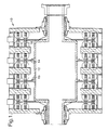
- Figure 1 is a cross-sectional view of a transverse flux motor having a rotor constructed in accordance with the present invention.
- Figure 2 is an enlarged view of part of one of the rotor rims shown in figure 1 having laminated pole pieces.
- Figure 3 is an enlarged cross-sectional view through one of the laminated pole pieces shown in figure 2 mounted in accordance with the present invention.
- a transverse flux motor generally indicated at 10 comprises a rotor and a stator assembly.
- the rotor assembly has four rotor discs 14 bolted to flanges 13 on a hollow shaft 12. Each disc 14 has four circumferential rotor rims 16 that support the active rotor components for four motor phases.
- Each rim 16 consists of a single row of alternate pole pieces 18 and permanent magnets 20, figure 2.
- Suitable magnet materials are the high-energy rare earth magnet materials such as samarium cobalt and neodymium iron boron.
- the pole pieces 18 are laminated and pre-bonded into a stack. Pre-bonding the laminations into a stack gives a discrete component that is easier to assemble onto the rotor 14.
- a bolt 22 passes through bolthole 21 to fasten the stack of laminations to the rotor disc 14, figure 3.
- a compressive force is applied to the laminated pole piece 18 via two annular members 24 and 26 made from glass reinforced plastic.
- the outer annular member 26 is tightened down using nuts 28 and a number of sprung washers 30.
- the sprung washers 30 are resilient so that the correct compressive force is maintained on the pole piece 18 regardless of relaxation in the stack of laminations and differential expansion of the rotor components. Retaining a compressive force on the laminated stack maintains the required structural stiffness and minimises deflections in the pole pieces 18 when in operation.
- the pole pieces 18 are mounted concentrically on the bolt 22 in a radially spaced relationship so that a clearance 23 is created between the bolt 22 and the pole pieces 18.
- the clearance 23 acts to insulate the bolt 22 from the pole pieces 18, which are made from a ferromagnetic material such as silicon-iron alloy.
- the pole pieces 18 are mounted in a radially spaced relationship with the bolt 22 by insulated annular members 27 located at either end.
- the annular members 27 are O-rings which are formed from a resilient material such as an elastomer.
- the O-rings 27 are self-centring and ensure that the laminations remain concentric.
- the O-rings 27 are recessed into the ends of the pole pieces 18 to maintain a small clearance 23 between the bolt 22 and the pole pieces 18. Only a small clearance 23 is required due to the modest electrical insulation requirements.
- the clearance 23 need only insulate against a voltage of the order of 1 volt in order to limit the power loss due to eddy currents.
- a clearance 23 of the order of 0.25mm is sufficient to insulate against a voltage of 1 volt whilst giving sufficient clearance to meet the demanding shock and vibration requirements of the transverse flux motor.
- An arrangement in accordance with the present invention offers the advantages that it is easier to assemble, it offers good and reliable concentricity whilst eliminating the need for tight tolerances.
Abstract

Description
- The present invention relates to a rotor disc for use in an electrical machine and in particular to the construction of an active rim on the rotor disc.
- Electrical machines, which operate in accordance with transverse flux principles, consist of an armature winding in the form of a circular coil co-axial with a rotor. The rotor consists of one or more active rims comprising a multiplicity of magnets and laminated poles, fastened to the disc. The armature winding links the flux generated by the permanent magnets mounted on the rim of the rotor disc by means of a series of stator cores.
- The rotor disc may support several rotor rims typically arranged in pairs on opposite sides of the disc. Each rotor rim is circumferential and consists of a single row of magnets and pole pieces.
- European patent 0779695-B, in the name of Rolls-Royce Power Engineering plc, describes an arrangement in which the laminations in each pole piece are clamped by one or more bolts. The bolts pass through the lamination stack and the rotor disc. It is necessary for the rotor poles, which are made from a ferromagnetic material such as silicon-iron alloy, to be electrically insulated from the bolts passing through them to minimise power losses due to eddy currents.
- Conventional methods of achieving the required insulation include providing an insulating coating on the surface of the bolt or sheathing the bolt with an insulated tube. The application of a coating to the bolt is expensive whilst the sheath may be damaged during installation and requires an additional assembly clearance which adversely affects build accuracy.
- The present invention seeks to provide an insulated pole piece, which is not expensive to produce, has adequate insulation integrity and which more accurately locates the pole piece relative to the disc.
- According to the present invention a rotor disc for use in an electrical machine has at least one circumferential rotor rim mounted thereon, the rotor rim comprises at least one row of alternate magnets and laminated pole pieces, the laminations in each pole piece being supported by at least one bolt which extends through the rotor disc, a clearance being provided between the laminations and the bolt passing therethrough. The clearance insulates the bolt from the laminations in each pole piece.
- Preferably the laminations are mounted concentrically on the bolt in a radially spaced relationship to provide the insulating clearance. This eases assembly of the rotor rim, as a close fit is not required between the laminated pole pieces and the bolt.
- The laminations may be bonded together to form a stack, the stack of bonded laminations being mounted concentrically on the bolt in a radially spaced relationship. Bonding the laminations into a stack gives a discrete component that is easier to assemble.
- In the preferred embodiment of the present invention the stack of bonded laminations is mounted concentrically on the bolt in a radially spaced relationship by the provision of insulated annular members at either end of the stack. The insulated annular members may be recessed into either end to minimise the insulating clearance over most of the stack length and ease assembly with small radial clearances.
- Preferably the insulated annular members are resilient and are formed from an elastomeric material, which allows them to be pressed into the recesses and ensures accurate location of the pole piece relative to the rotor disc.
- The laminated pole pieces may be compressed. Preferably resilient means, such as nuts and sprung washers, are provided on the bolt for compressing the laminated pole pieces. The nuts and spring washers maintain the correct compressive force on the laminated pole pieces throughout operation.
- The present invention will now be described with reference to the accompanying drawings in which;
- Figure 1 is a cross-sectional view of a transverse flux motor having a rotor constructed in accordance with the present invention.
- Figure 2 is an enlarged view of part of one of the rotor rims shown in figure 1 having laminated pole pieces.
- Figure 3 is an enlarged cross-sectional view through one of the laminated pole pieces shown in figure 2 mounted in accordance with the present invention.
- Referring to figure 1 a transverse flux motor, generally indicated at 10 comprises a rotor and a stator assembly.
- The rotor assembly has four
rotor discs 14 bolted toflanges 13 on ahollow shaft 12. Eachdisc 14 has fourcircumferential rotor rims 16 that support the active rotor components for four motor phases. - Each
rim 16 consists of a single row ofalternate pole pieces 18 andpermanent magnets 20, figure 2. Suitable magnet materials are the high-energy rare earth magnet materials such as samarium cobalt and neodymium iron boron. - The
pole pieces 18 are laminated and pre-bonded into a stack. Pre-bonding the laminations into a stack gives a discrete component that is easier to assemble onto therotor 14. Abolt 22 passes throughbolthole 21 to fasten the stack of laminations to therotor disc 14, figure 3. - A compressive force is applied to the laminated
pole piece 18 via twoannular members annular member 26 is tightened down usingnuts 28 and a number ofsprung washers 30. - The
sprung washers 30 are resilient so that the correct compressive force is maintained on thepole piece 18 regardless of relaxation in the stack of laminations and differential expansion of the rotor components. Retaining a compressive force on the laminated stack maintains the required structural stiffness and minimises deflections in thepole pieces 18 when in operation. - The
pole pieces 18 are mounted concentrically on thebolt 22 in a radially spaced relationship so that aclearance 23 is created between thebolt 22 and thepole pieces 18. Theclearance 23 acts to insulate thebolt 22 from thepole pieces 18, which are made from a ferromagnetic material such as silicon-iron alloy. - The
pole pieces 18 are mounted in a radially spaced relationship with thebolt 22 by insulatedannular members 27 located at either end. In the preferred embodiment of the present invention theannular members 27 are O-rings which are formed from a resilient material such as an elastomer. The O-rings 27 are self-centring and ensure that the laminations remain concentric. - The O-
rings 27 are recessed into the ends of thepole pieces 18 to maintain asmall clearance 23 between thebolt 22 and thepole pieces 18. Only asmall clearance 23 is required due to the modest electrical insulation requirements. Theclearance 23 need only insulate against a voltage of the order of 1 volt in order to limit the power loss due to eddy currents. In the preferred embodiment of the present invention aclearance 23 of the order of 0.25mm is sufficient to insulate against a voltage of 1 volt whilst giving sufficient clearance to meet the demanding shock and vibration requirements of the transverse flux motor. - An arrangement in accordance with the present invention offers the advantages that it is easier to assemble, it offers good and reliable concentricity whilst eliminating the need for tight tolerances.
Claims (10)
- A rotor disc 14 for use in an electrical machine 10 has at least one circumferential rotor rim 16 mounted thereon, the rotor rim 16 comprising at least one row of alternate magnets 20 and laminated pole pieces 18, the laminations in each pole piece 18 being supported by at least one bolt 22 which extends through the rotor disc 14, characterised in that a clearance 23 is provided to electrically insulate the laminations from the bolt 22 passing therethrough.
- A rotor disc 14 as claimed in claim 1 characterised in that the clearance 23 is provided by mounting the laminations concentrically on the bolt 22 in a radially spaced relationship.
- A rotor disc 14 as claimed in claim 1 or claim 2 characterised in that the laminations are bonded together to form a stack.
- A rotor disc 14 as claimed in claim 3 characterised in that the stack of bonded laminations is mounted concentrically on the bolt 22 in a radially spaced relationship by the provision of annular members 27 which are insulated at either end of the stack.
- A rotor disc 14 as claimed in claim 4 characterised in that the insulated annular members 27 are recessed into either end of the stack.
- A rotor disc 14 as claimed in claim 4 or claim 5 characterised in that the insulated annular members 27 are resilient.
- A rotor disc 14 as claimed in claim 6 characterised in that the annular members 27 are formed from an elastomeric material.
- A rotor disc 14 as claimed in any preceding claim characterised in that means 30 are provided on the bolt 22 for compressing the laminated pole pieces 18.
- A rotor disc 14 as claimed in claim 8 characterised in that the means 30 for compressing the laminated pole pieces 18 is resilient to maintain the correct compressive force on the laminated pole pieces 18 throughout operation.
- A rotor disc 14 as claimed in claim 9 characterised in that the means 30 for compressing the laminated pole pieces are nuts 28 and sprung washers 30.
Applications Claiming Priority (2)
| Application Number | Priority Date | Filing Date | Title |
|---|---|---|---|
| GB0001121 | 2000-01-19 | ||
| GBGB0001121.3A GB0001121D0 (en) | 2000-01-19 | 2000-01-19 | Rotor disc |
Publications (3)
| Publication Number | Publication Date |
|---|---|
| EP1122859A2 true EP1122859A2 (en) | 2001-08-08 |
| EP1122859A3 EP1122859A3 (en) | 2002-01-02 |
| EP1122859B1 EP1122859B1 (en) | 2006-08-30 |
Family
ID=9883914
Family Applications (1)
| Application Number | Title | Priority Date | Filing Date |
|---|---|---|---|
| EP00311595A Expired - Lifetime EP1122859B1 (en) | 2000-01-19 | 2000-12-21 | Rotor disc for an electrical machine |
Country Status (4)
| Country | Link |
|---|---|
| US (1) | US6741010B2 (en) |
| EP (1) | EP1122859B1 (en) |
| DE (1) | DE60030402T2 (en) |
| GB (1) | GB0001121D0 (en) |
Cited By (5)
| Publication number | Priority date | Publication date | Assignee | Title |
|---|---|---|---|---|
| WO2003084025A1 (en) * | 2002-04-01 | 2003-10-09 | Nissan Motor Co., Ltd. | Stator mounting for a double rotor electric motor |
| US6741010B2 (en) * | 2000-01-19 | 2004-05-25 | Rolls Royce Plc | Rotor disc assembly having rotor rim with alternate magnets and laminated pole pieces |
| WO2009121760A1 (en) * | 2008-04-03 | 2009-10-08 | Robert Bosch Gmbh | Electric machine |
| ITFI20080166A1 (en) * | 2008-09-03 | 2010-03-04 | Leonardo Lenzi | METHOD FOR THE PRODUCTION OF THE STATOR OF AN ELECTRIC MACHINE. |
| EP2932580A4 (en) * | 2012-12-17 | 2016-08-24 | Active Power Inc | Systems and methods for securing a rotor apparatus |
Families Citing this family (32)
| Publication number | Priority date | Publication date | Assignee | Title |
|---|---|---|---|---|
| DE10057633A1 (en) * | 2000-11-21 | 2002-06-06 | Bosch Gmbh Robert | Anchor and method of making an anchor |
| US8004127B2 (en) * | 2002-12-06 | 2011-08-23 | Foster-Miller, Inc. | Rotary reluctance motor |
| CA2421606C (en) * | 2003-03-06 | 2011-06-14 | General Electric Canada Inc. | Insulated core stud for rotor and stator laminations |
| US7081696B2 (en) | 2004-08-12 | 2006-07-25 | Exro Technologies Inc. | Polyphasic multi-coil generator |
| KR101045647B1 (en) * | 2004-10-05 | 2011-07-01 | 엘지전자 주식회사 | Motor Bracket Fastening Structure |
| JP4010319B2 (en) * | 2005-02-09 | 2007-11-21 | ダイキン工業株式会社 | Core and rotor, motor and compressor |
| US7285890B2 (en) * | 2005-03-30 | 2007-10-23 | Comprehensive Power, Inc. | Magnet retention on rotors |
| US20060255679A1 (en) * | 2005-05-13 | 2006-11-16 | Dine Pieter V | Apparatus for pole pieces |
| US7358637B2 (en) * | 2005-11-04 | 2008-04-15 | Canopy Technologies, Llc | Method of compressing lamination stacks for permanent magnet rotor |
| AU2007257187A1 (en) | 2006-06-08 | 2007-12-13 | Exro Technologies Inc. | Poly-phasic multi-coil generator |
| US8558425B2 (en) * | 2006-10-26 | 2013-10-15 | Deere & Company | Motor having stator with generally planar windings |
| US20080100166A1 (en) * | 2006-10-26 | 2008-05-01 | Deere & Company | Motor having stator with generally planar windings |
| US7919898B2 (en) * | 2007-06-21 | 2011-04-05 | Nidec Motor Corporation | Rotor core assembly for electric motor |
| US8232695B2 (en) | 2007-07-09 | 2012-07-31 | Clearwater Holdings, Ltd | Electromagnetic machine with independent removable coils, modular parts and self sustained passive magnetic bearing |
| US7816830B2 (en) * | 2007-08-16 | 2010-10-19 | Gary Dickes | Permanent magnet alternator with segmented construction |
| US7830057B2 (en) * | 2008-08-29 | 2010-11-09 | Hamilton Sundstrand Corporation | Transverse flux machine |
| WO2010036221A1 (en) | 2008-09-26 | 2010-04-01 | Clearwater Holdings, Ltd. | Permanent magnet operating machine |
| DE102008043661A1 (en) * | 2008-11-12 | 2010-05-20 | Robert Bosch Gmbh | Shaft for an electric machine, in particular for a motor generator |
| US8319380B2 (en) * | 2009-09-25 | 2012-11-27 | Siemens Industry, Inc. | Method of tuning bending and torsion stiffness of ducted rotor core of an induction motor |
| JP5507967B2 (en) * | 2009-11-09 | 2014-05-28 | 株式会社日立製作所 | Rotating electric machine |
| DE102012215241A1 (en) * | 2012-08-28 | 2014-03-06 | Siemens Aktiengesellschaft | Rotor of an electric machine and electric machine |
| DE102012215236A1 (en) * | 2012-08-28 | 2014-03-06 | Siemens Aktiengesellschaft | Rotor of an electric machine and electric machine |
| US10505412B2 (en) | 2013-01-24 | 2019-12-10 | Clearwater Holdings, Ltd. | Flux machine |
| JP6121967B2 (en) * | 2014-10-02 | 2017-04-26 | ファナック株式会社 | Rotor with balancer weight and motor |
| US11081996B2 (en) | 2017-05-23 | 2021-08-03 | Dpm Technologies Inc. | Variable coil configuration system control, apparatus and method |
| US11189434B2 (en) | 2017-09-08 | 2021-11-30 | Clearwater Holdings, Ltd. | Systems and methods for enhancing electrical energy storage |
| CN111344933B (en) | 2017-10-29 | 2023-04-07 | 清水控股有限公司 | Modular electromagnetic machine and methods of use and manufacture thereof |
| US11722026B2 (en) | 2019-04-23 | 2023-08-08 | Dpm Technologies Inc. | Fault tolerant rotating electric machine |
| US11848595B2 (en) * | 2019-11-07 | 2023-12-19 | Hyperloop Technologies, Inc. | Channel segment for a track of a mover device |
| DE102020121976A1 (en) | 2020-08-21 | 2022-02-24 | Schunk Electronic Solutions Gmbh | Rotor for an electric internal or external rotor motor, system of several rotors and electric internal or external rotor motor |
| EP4315556A1 (en) | 2021-05-04 | 2024-02-07 | Exro Technologies Inc. | Battery control systems and methods |
| WO2022236424A1 (en) | 2021-05-13 | 2022-11-17 | Exro Technologies Inc. | Method and appartus to drive coils of a multiphase electric machine |
Citations (5)
| Publication number | Priority date | Publication date | Assignee | Title |
|---|---|---|---|---|
| US3447010A (en) * | 1966-06-08 | 1969-05-27 | Emerson Electric Co | Hermetic motor stator with insulated mounting bolts |
| US3693035A (en) * | 1970-09-15 | 1972-09-19 | Black & Decker Mfg Co | Double insulated field mounting for universal motor |
| JPS6218939A (en) * | 1985-07-18 | 1987-01-27 | Matsushita Refrig Co | Structure of installation of electric motor for compressor |
| EP0779695A1 (en) * | 1995-12-14 | 1997-06-18 | ROLLS-ROYCE POWER ENGINEERING plc | Rotor disc |
| JPH11266555A (en) * | 1998-03-16 | 1999-09-28 | Toshiba Corp | Rotor for rotary electric machine |
Family Cites Families (26)
| Publication number | Priority date | Publication date | Assignee | Title |
|---|---|---|---|---|
| GB460040A (en) | 1935-07-25 | 1937-01-20 | Andrew Allison | Improvements in and connected with the laminated magnetic cores used in dynamo electric machinery |
| US3200275A (en) * | 1960-01-20 | 1965-08-10 | Electrolux Ab | Electric motor housings |
| US3445698A (en) * | 1967-06-29 | 1969-05-20 | Reliance Electric & Eng Co | Dynamoelectric machine with junction box on yoke and end bell |
| US3590292A (en) * | 1969-11-28 | 1971-06-29 | American Mach & Foundry | Electric motor construction |
| US3832581A (en) * | 1972-03-31 | 1974-08-27 | G Jack | Multi-armature and concentric motors |
| US3992641A (en) * | 1974-11-22 | 1976-11-16 | Westinghouse Electric Corporation | Polyphase disc reluctance motor |
| JPS5445712A (en) * | 1977-09-19 | 1979-04-11 | Hitachi Ltd | Motor |
| US4208600A (en) * | 1978-04-21 | 1980-06-17 | General Electric Company | Disk/drum acyclic machine |
| US4306168A (en) * | 1978-10-31 | 1981-12-15 | Emerson Electric Co. | System and method of securing end shields to the stator assembly of a dynamolelectric machine |
| US4510680A (en) * | 1982-12-27 | 1985-04-16 | General Electric Company | Method of making a permanent magnet rotor |
| US4477745A (en) * | 1983-12-15 | 1984-10-16 | Lux Gregory F | Disc rotor permanent magnet generator |
| JPS62193537A (en) | 1986-02-17 | 1987-08-25 | Fanuc Ltd | Permanent field rotor |
| JPH01157565U (en) * | 1988-04-12 | 1989-10-31 | ||
| FR2655214B1 (en) * | 1989-11-27 | 1992-02-07 | Alsthom Gec | MAGNET MOTOR ROTOR. |
| WO2004075379A1 (en) * | 1992-03-18 | 2004-09-02 | Kazuto Sakai | Axial gap rotaitng electric machine |
| US5396140A (en) * | 1993-05-28 | 1995-03-07 | Satcon Technology, Corp. | Parallel air gap serial flux A.C. electrical machine |
| DE4439690A1 (en) * | 1994-11-07 | 1996-05-09 | Philips Patentverwaltung | Induction motor |
| CA2175510C (en) * | 1995-05-02 | 2005-02-01 | Masao Iwata | Magneto electric generator rotor and an implement for removing this rotor |
| GB9525546D0 (en) * | 1995-12-14 | 1996-02-14 | Rolls Royce Power Eng | Rotor disc |
| US5894183A (en) * | 1996-10-29 | 1999-04-13 | Caterpillar Inc. | Permanent magnet generator rotor |
| US5982074A (en) * | 1996-12-11 | 1999-11-09 | Advanced Technologies Int., Ltd. | Axial field motor/generator |
| US5952755A (en) * | 1997-03-18 | 1999-09-14 | Electric Boat Corporation | Permanent magnet motor rotor |
| DE19737391A1 (en) * | 1997-08-27 | 1999-03-04 | Magnet Motor Gmbh | Electrical machine, the rotor of which is made up of permanent magnets and magnetic flux guide pieces |
| US6051905A (en) * | 1998-09-17 | 2000-04-18 | Clark; Richard | Homopolar generator |
| GB0001121D0 (en) * | 2000-01-19 | 2000-03-08 | Rolls Royce Plc | Rotor disc |
| US6603232B2 (en) * | 2001-11-02 | 2003-08-05 | Electric Boat Corporation | Permanent magnet retaining arrangement for high speed rotors |
-
2000
- 2000-01-19 GB GBGB0001121.3A patent/GB0001121D0/en not_active Ceased
- 2000-12-21 EP EP00311595A patent/EP1122859B1/en not_active Expired - Lifetime
- 2000-12-21 DE DE60030402T patent/DE60030402T2/en not_active Expired - Lifetime
-
2001
- 2001-01-08 US US09/755,114 patent/US6741010B2/en not_active Expired - Fee Related
Patent Citations (5)
| Publication number | Priority date | Publication date | Assignee | Title |
|---|---|---|---|---|
| US3447010A (en) * | 1966-06-08 | 1969-05-27 | Emerson Electric Co | Hermetic motor stator with insulated mounting bolts |
| US3693035A (en) * | 1970-09-15 | 1972-09-19 | Black & Decker Mfg Co | Double insulated field mounting for universal motor |
| JPS6218939A (en) * | 1985-07-18 | 1987-01-27 | Matsushita Refrig Co | Structure of installation of electric motor for compressor |
| EP0779695A1 (en) * | 1995-12-14 | 1997-06-18 | ROLLS-ROYCE POWER ENGINEERING plc | Rotor disc |
| JPH11266555A (en) * | 1998-03-16 | 1999-09-28 | Toshiba Corp | Rotor for rotary electric machine |
Non-Patent Citations (2)
| Title |
|---|
| PATENT ABSTRACTS OF JAPAN vol. 11, no. 190 (E-517), 18 June 1987 (1987-06-18) & JP 62 018939 A (MATSUSHITA REFRIG CO), 27 January 1987 (1987-01-27) * |
| PATENT ABSTRACTS OF JAPAN vol. 1999, no. 14, 22 December 1999 (1999-12-22) & JP 11 266555 A (TOSHIBA CORP), 28 September 1999 (1999-09-28) * |
Cited By (8)
| Publication number | Priority date | Publication date | Assignee | Title |
|---|---|---|---|---|
| US6741010B2 (en) * | 2000-01-19 | 2004-05-25 | Rolls Royce Plc | Rotor disc assembly having rotor rim with alternate magnets and laminated pole pieces |
| WO2003084025A1 (en) * | 2002-04-01 | 2003-10-09 | Nissan Motor Co., Ltd. | Stator mounting for a double rotor electric motor |
| US7026742B2 (en) | 2002-04-01 | 2006-04-11 | Nissan Motor Co., Ltd. | Stator mounting for a double rotor electric motor |
| WO2009121760A1 (en) * | 2008-04-03 | 2009-10-08 | Robert Bosch Gmbh | Electric machine |
| ITFI20080166A1 (en) * | 2008-09-03 | 2010-03-04 | Leonardo Lenzi | METHOD FOR THE PRODUCTION OF THE STATOR OF AN ELECTRIC MACHINE. |
| EP2932580A4 (en) * | 2012-12-17 | 2016-08-24 | Active Power Inc | Systems and methods for securing a rotor apparatus |
| EP2932586A4 (en) * | 2012-12-17 | 2016-08-24 | Active Power Inc | Rotor assembly apparatus and methods |
| EP2932585A4 (en) * | 2012-12-17 | 2016-08-24 | Active Power Inc | Laminated rotor apparatus and methods |
Also Published As
| Publication number | Publication date |
|---|---|
| DE60030402D1 (en) | 2006-10-12 |
| GB0001121D0 (en) | 2000-03-08 |
| US6741010B2 (en) | 2004-05-25 |
| EP1122859B1 (en) | 2006-08-30 |
| EP1122859A3 (en) | 2002-01-02 |
| DE60030402T2 (en) | 2006-12-14 |
| US20010008356A1 (en) | 2001-07-19 |
Similar Documents
| Publication | Publication Date | Title |
|---|---|---|
| EP1122859B1 (en) | Rotor disc for an electrical machine | |
| US3531670A (en) | Rotary electrical apparatus having metallic sleeve for embracing the peripheral sections of permanent magnet rotor | |
| US7030529B2 (en) | Electrical machines, especially engines excited by permanent magnets | |
| US10608490B2 (en) | Axial flux machine | |
| KR100898202B1 (en) | Stator and motor, to which the stator is applied, and method of manufacturing the stator | |
| US6515390B1 (en) | Electric drive apparatus with a rotor having two magnetizied disks | |
| CN1866688B (en) | System and method for magnetization of permanent magnet rotors in electrical machines | |
| US4027229A (en) | Regulatable permanent magnet alternator | |
| US5877578A (en) | Rotor disc construction for use in an electrical machine | |
| KR101707389B1 (en) | Rotor for an electrical machine | |
| US20070247017A1 (en) | Axial-Flux, Permanent Magnet Electrical Machine | |
| EP2020662A2 (en) | Assembly and method for magnetization of permanent magnet rotors in electrical machines | |
| AU2005218051A1 (en) | Rotor for an electric motor and corresponding electric motor | |
| EP0429729A1 (en) | Electric machines with ironcore disk armatures | |
| WO2013116506A1 (en) | Electric machines and methods of making same | |
| EP1925065A1 (en) | A device and method to clamp and lock permanent magnets and improve cooling within a rotating electrical machine | |
| US5886449A (en) | Electrical machine | |
| JP2001119872A (en) | Synchronous rotating electric machine, wind turbine power generator, and manufacturing methods for them | |
| EP0762618B1 (en) | Transverse flux electrical machine | |
| WO2007083724A1 (en) | Gap winding type motor | |
| US3462627A (en) | Annular rotor supporting structure for a synchronous machine | |
| KR101247683B1 (en) | Amorphous Stator, Electric Motor Using the Same, and Producing Method thereof | |
| JPH05219666A (en) | Stator for rotating electric machine | |
| JP2006246622A (en) | Stator, rotating electric machine and core therefor | |
| JP2020137387A (en) | Rotary motor and linear motor |
Legal Events
| Date | Code | Title | Description |
|---|---|---|---|
| PUAI | Public reference made under article 153(3) epc to a published international application that has entered the european phase |
Free format text: ORIGINAL CODE: 0009012 |
|
| AK | Designated contracting states |
Kind code of ref document: A2 Designated state(s): AT BE CH CY DE DK ES FI FR GB GR IE IT LI LU MC NL PT SE TR Kind code of ref document: A2 Designated state(s): DE FR GB IT |
|
| AX | Request for extension of the european patent |
Free format text: AL;LT;LV;MK;RO;SI |
|
| PUAL | Search report despatched |
Free format text: ORIGINAL CODE: 0009013 |
|
| AK | Designated contracting states |
Kind code of ref document: A3 Designated state(s): AT BE CH CY DE DK ES FI FR GB GR IE IT LI LU MC NL PT SE TR |
|
| AX | Request for extension of the european patent |
Free format text: AL;LT;LV;MK;RO;SI |
|
| 17P | Request for examination filed |
Effective date: 20011121 |
|
| AKX | Designation fees paid |
Free format text: DE FR GB IT |
|
| GRAP | Despatch of communication of intention to grant a patent |
Free format text: ORIGINAL CODE: EPIDOSNIGR1 |
|
| GRAS | Grant fee paid |
Free format text: ORIGINAL CODE: EPIDOSNIGR3 |
|
| GRAA | (expected) grant |
Free format text: ORIGINAL CODE: 0009210 |
|
| AK | Designated contracting states |
Kind code of ref document: B1 Designated state(s): DE FR GB IT |
|
| REG | Reference to a national code |
Ref country code: GB Ref legal event code: FG4D |
|
| REF | Corresponds to: |
Ref document number: 60030402 Country of ref document: DE Date of ref document: 20061012 Kind code of ref document: P |
|
| ET | Fr: translation filed | ||
| PLBE | No opposition filed within time limit |
Free format text: ORIGINAL CODE: 0009261 |
|
| STAA | Information on the status of an ep patent application or granted ep patent |
Free format text: STATUS: NO OPPOSITION FILED WITHIN TIME LIMIT |
|
| 26N | No opposition filed |
Effective date: 20070531 |
|
| PGFP | Annual fee paid to national office [announced via postgrant information from national office to epo] |
Ref country code: GB Payment date: 20121227 Year of fee payment: 13 |
|
| PGFP | Annual fee paid to national office [announced via postgrant information from national office to epo] |
Ref country code: DE Payment date: 20121231 Year of fee payment: 13 |
|
| PGFP | Annual fee paid to national office [announced via postgrant information from national office to epo] |
Ref country code: FR Payment date: 20131217 Year of fee payment: 14 Ref country code: IT Payment date: 20131223 Year of fee payment: 14 |
|
| REG | Reference to a national code |
Ref country code: DE Ref legal event code: R119 Ref document number: 60030402 Country of ref document: DE |
|
| GBPC | Gb: european patent ceased through non-payment of renewal fee |
Effective date: 20131221 |
|
| REG | Reference to a national code |
Ref country code: DE Ref legal event code: R119 Ref document number: 60030402 Country of ref document: DE Effective date: 20140701 |
|
| PG25 | Lapsed in a contracting state [announced via postgrant information from national office to epo] |
Ref country code: DE Free format text: LAPSE BECAUSE OF NON-PAYMENT OF DUE FEES Effective date: 20140701 |
|
| PG25 | Lapsed in a contracting state [announced via postgrant information from national office to epo] |
Ref country code: GB Free format text: LAPSE BECAUSE OF NON-PAYMENT OF DUE FEES Effective date: 20131221 |
|
| REG | Reference to a national code |
Ref country code: FR Ref legal event code: ST Effective date: 20150831 |
|
| PG25 | Lapsed in a contracting state [announced via postgrant information from national office to epo] |
Ref country code: FR Free format text: LAPSE BECAUSE OF NON-PAYMENT OF DUE FEES Effective date: 20141231 |
|
| PG25 | Lapsed in a contracting state [announced via postgrant information from national office to epo] |
Ref country code: IT Free format text: LAPSE BECAUSE OF NON-PAYMENT OF DUE FEES Effective date: 20141221 |