EP1122576A2 - Système optique - Google Patents
Système optique Download PDFInfo
- Publication number
- EP1122576A2 EP1122576A2 EP01101318A EP01101318A EP1122576A2 EP 1122576 A2 EP1122576 A2 EP 1122576A2 EP 01101318 A EP01101318 A EP 01101318A EP 01101318 A EP01101318 A EP 01101318A EP 1122576 A2 EP1122576 A2 EP 1122576A2
- Authority
- EP
- European Patent Office
- Prior art keywords
- light source
- microtiter plate
- light
- lens
- optical system
- Prior art date
- Legal status (The legal status is an assumption and is not a legal conclusion. Google has not performed a legal analysis and makes no representation as to the accuracy of the status listed.)
- Granted
Links
Images

Classifications
-
- G—PHYSICS
- G02—OPTICS
- G02B—OPTICAL ELEMENTS, SYSTEMS OR APPARATUS
- G02B21/00—Microscopes
- G02B21/34—Microscope slides, e.g. mounting specimens on microscope slides
-
- G—PHYSICS
- G02—OPTICS
- G02B—OPTICAL ELEMENTS, SYSTEMS OR APPARATUS
- G02B21/00—Microscopes
- G02B21/06—Means for illuminating specimens
- G02B21/08—Condensers
- G02B21/088—Condensers for both incident illumination and transillumination
Definitions
- the invention relates to an optical system with a magnifying Objective, which is a transparent microtiter plate depicts an analysis preparation in several, cup-shaped cavities, and with a lens side the incident light illumination arranged on the microtiter plate to illuminate the one picked up by the microtiter plate Analytical specimen.
- a magnifying Objective which is a transparent microtiter plate depicts an analysis preparation in several, cup-shaped cavities, and with a lens side the incident light illumination arranged on the microtiter plate to illuminate the one picked up by the microtiter plate Analytical specimen.
- Optical systems of the type specified are particularly to evaluate analyzes according to ELISPOT (Enzyme Linked Immuno Spot Assay). This procedure became Detection of individual antibody-secreting ⁇ cells developed. It is also used to detect cytokine excretions special subgroups of leukocytes or T lymphocytes from peripheral blood as well as from monocytes and granulocytes.
- the ELISPOT process uses proteins separated from the cells are detected with antibodies and punctiform using special dyeing processes Spots, so-called spots, which are permanent and be evaluated both visually and analytically can.
- MTP microtiter plates
- the microtiter plates consist of small, interconnected beakers, also cavities or wells called.
- the bottom of the cup is usually one Filter membrane formed on which the punctiform analysis objects be liable.
- a standard MTP size has 96 cavities.
- ELISPOT analysis the on which the Measuring surface forming the bottom of the cavities of an MTP visible small points of up to 1,500 per cavity can be counted.
- automatically working evaluation devices used the surface of the bottom of each Show cavities enlarged about 20 to 40 times, with record an electronic camera and the digitized Evaluate image data using an electronic computer.
- the MTP for positioning the magnifying lens initially from a greater distance without any significant enlargement captured and based on this picture the exact position of the individual cavities measured and saved.
- the magnifying Objective automatically positioned over the individual cavities become.
- the construction effort for the optical system and the positioning table is relatively high and for storage the position data becomes additional storage space needed.
- EP 0 504 940 A2 describes an illumination device for known a system microscope with a revolver objective, where the light from a light source on the lens side Optical fibers ring-shaped with respect to the optical axis via an annular condenser lens and at the same time on the side facing away from the lens via a lens system, a Deflecting mirror and a condenser lens along the optical Axis is aimed at the object to be viewed. A Observation of microtiter plates is not intended here.
- a lighting device for a microscope with a Plurality of flatly arranged lighting elements, which can be controlled individually and a desired one Illumination pattern for the object to be examined specify, is known from DE 37 34 691 C2.
- the as active Semiconductor sources are trained lighting elements as transmitted light illumination behind a diffuser disc arranged and can be ignited in an annular arrangement become.
- the object of the invention is to provide an optical system to create the type with which the measuring surfaces a transparent MTP without disturbing the image evaluation Reflections can be mapped.
- the object is achieved in that the Incident light through a diffuse, concentric to the ring-shaped light source arranged on the optical axis is formed and that on the side facing away from the lens Microtiter plate a second essentially punctiform and there is a light source on the optical axis which is the analytical specimen with transmitted light and with a higher one than the ring-shaped light source Luminance illuminated.
- the outside area of the MTP lying on the measuring surface of the filter membrane completely white.
- the prepared measuring surface rises on the other hand, it turns slightly gray against this light background. Reflections and material disturbances in the outside of the one to be evaluated Measuring area lying area are no longer visible.
- the approximately punctiform Light source behind a diffuser disc can do this effect and the contrast between the measuring surface and Background becomes even clearer.
- the light the essentially point-shaped light source with the help reflective or refractive agent on the lens-facing Side of each lying on the optical axis Cavity of the microtiter plate is bundled.
- Farther can be provided that the light intensity of the annular Light source for incident lighting and / or point-shaped Adjustable light source for transmitted light illumination is. This allows the imaging quality of the optical Systems to different transparency of the filter membranes of microtiter plates.
- the lens-side overhead lighting can be according to a another proposal of the invention also by redirecting Light, e.g. diffuse scattered light, from the lens facing away Side on the lens side of the microtiter plate can be achieved.
- the deflection can be done with the help of reflective surfaces or light-guiding elements that are in the arranged essentially concentrically to the optical axis are.
- the optical system according to the invention has the advantage that the measuring surfaces of the filter membranes of an MTP are error-free map and have it evaluated. Also a little inaccurate Centering of the measuring surface to the optical axis is impaired the measurement accuracy is not, so the requirements to the positioning accuracy of the table that the MTP carries and can move in the X and Y direction, less must be high and the table correspondingly cheaper can be manufactured.
- the clear lifting of the measuring surfaces from the surrounding bright background it does still possible to analyze the position of the measuring surfaces to be determined and automatically controlled by the table to move to the center of the picture. An automatic evaluation microtiter plates are therefore easily possible.
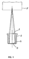
- Figure 1 shows a cross section through a cavity 1 a commercially available microtiter plate as used for ELISPOT analyzes is used.
- the cavity 1 consists of one cylindrical tube 2, which consists of a transparent Plastic is made.
- the bottom opening of the tube 2 is through a filter membrane glued to the tube 2 3 closed, which forms the bottom of the cavity 1 and is translucent.
- the cavity of the cavity 1 facing surface of the filter membrane 3 forms the Measuring surface 4, on which the punctiform analysis objects be liable.
- the measuring surface 4 shown enlarged with the aid of an optical system 5 and the enlarged image for image analysis processing taken by an electronic camera.
- the one in FIG The optical path shown illustrates that of the optical one System 5 shown areas of the cavity 1.
- the cylindrical Wall of the cavity 1 as a surrounding the image of the measuring surface 4 Wreath is pictured. Reflections on the measuring surface 4 on the cylindrical wall of the cavity 1 can therefore are also depicted and, since they are difficult to see to distinguish the image of the measuring surface 4, errors lead in the evaluation.
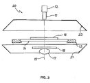
- FIG. 2 shows the structure of a microscope according to the invention 10, with which an image of the surrounding the measuring surface Wall area of a cavity can be prevented.
- the optical system 10 includes a magnifying lens 11 a camera 12 which can be moved in the X and Y directions
- Table 13 with a transparent support plate 14 are arranged.
- annular light source 15 for example an LED diffuser lamp, with which the arranged on the carrier plate 14 Microtiter plate 16 is illuminated from above.
- Below the support plate 14 of the table 13 is a point Light source 17 arranged with a diffuser disc 18.
- the light source 17 can be narrow of several light-emitting diodes arranged together are formed. Both Light sources 15 and 17 are to the optical axis 19 of the Centered lens 11.
- the illuminance of the light source 17 is significantly larger than that of the light source 15.
- both below and 13 ring-shaped reflective surfaces also above the table 21, 22 are provided which are diffusely reflective Have surface and stray light from the transmitted light deflect the light source 17 so that a diffuse, homogeneous illumination of the side facing the lens 11 the microtiter plate 16 in the area of the shown Measuring area is achieved.
- the luminance of the incident light deflected Scattered light significantly less than that in Transmitted light directed towards the analyte the light source 17, with an image in an analogous manner of the wall area of the cavity captured by the lens avoided is.
Applications Claiming Priority (2)
| Application Number | Priority Date | Filing Date | Title |
|---|---|---|---|
| DE10003789A DE10003789C1 (de) | 2000-01-28 | 2000-01-28 | Mikroskop |
| DE10003789 | 2000-01-28 |
Publications (3)
| Publication Number | Publication Date |
|---|---|
| EP1122576A2 true EP1122576A2 (fr) | 2001-08-08 |
| EP1122576A3 EP1122576A3 (fr) | 2004-01-14 |
| EP1122576B1 EP1122576B1 (fr) | 2006-03-22 |
Family
ID=7629093
Family Applications (1)
| Application Number | Title | Priority Date | Filing Date |
|---|---|---|---|
| EP01101318A Expired - Lifetime EP1122576B1 (fr) | 2000-01-28 | 2001-01-20 | Système optique |
Country Status (3)
| Country | Link |
|---|---|
| US (1) | US6384989B1 (fr) |
| EP (1) | EP1122576B1 (fr) |
| DE (2) | DE10003789C1 (fr) |
Cited By (1)
| Publication number | Priority date | Publication date | Assignee | Title |
|---|---|---|---|---|
| DE102004016361A1 (de) * | 2004-04-01 | 2005-11-03 | Cybio Ag | Optisches Analysenmessgerät für Fluoreszenzmessungen an Multiprobenträgern |
Families Citing this family (3)
| Publication number | Priority date | Publication date | Assignee | Title |
|---|---|---|---|---|
| US6597522B2 (en) * | 2000-01-28 | 2003-07-22 | Werner Freber | Optical system |
| US20080280310A1 (en) * | 2007-05-09 | 2008-11-13 | Louis Panagopoulos | Testing for Blood Group Immunological Reaction Without the Use of Anti-Human Globulin |
| DE102014107934A1 (de) * | 2014-06-05 | 2015-12-17 | Carl Zeiss Microscopy Gmbh | Verfahren zur mikroskopischen Abbildung von Proben an Böden von mit Fluid befüllten Töpfchen einer Mikrotiterplatte |
Citations (7)
| Publication number | Priority date | Publication date | Assignee | Title |
|---|---|---|---|---|
| DE3734691A1 (de) * | 1986-10-16 | 1988-04-28 | Olympus Optical Co | Beleuchtungsvorrichtung fuer mikroskope |
| US4806776A (en) * | 1980-03-10 | 1989-02-21 | Kley Victor B | Electrical illumination and detecting apparatus |
| EP0504940A2 (fr) * | 1991-03-22 | 1992-09-23 | Olympus Optical Co., Ltd | Dispositif d'illumination pour un microscope |
| WO1998007022A1 (fr) * | 1996-08-16 | 1998-02-19 | Imaging Research, Inc. | Systeme numerique d'imagerie pour des plaques de puits, des gels et taches |
| US5752767A (en) * | 1995-10-26 | 1998-05-19 | Illumination Technologies Inc. | Diffuse ring illuminator |
| WO1998028075A1 (fr) * | 1996-12-20 | 1998-07-02 | Imaging Research Inc. | Plaque a micro-puits pour imagerie d'essais en fluorescence, chimiluminescence, bioluminescence et colorimetrie |
| DE19748211A1 (de) * | 1997-10-31 | 1999-05-06 | Zeiss Carl Fa | Optisches Array-System und Reader für Mikrotiterplatten |
Family Cites Families (2)
| Publication number | Priority date | Publication date | Assignee | Title |
|---|---|---|---|---|
| DE9104079U1 (fr) * | 1991-04-04 | 1991-08-01 | Weidemann, Peter, 2080 Pinneberg, De | |
| DE19541233B4 (de) * | 1994-11-17 | 2006-04-06 | Carl Zeiss | Objekttisch für Mikroskope |
-
2000
- 2000-01-28 DE DE10003789A patent/DE10003789C1/de not_active Expired - Fee Related
- 2000-11-15 US US09/713,623 patent/US6384989B1/en not_active Expired - Lifetime
-
2001
- 2001-01-20 DE DE50109246T patent/DE50109246D1/de not_active Expired - Lifetime
- 2001-01-20 EP EP01101318A patent/EP1122576B1/fr not_active Expired - Lifetime
Patent Citations (7)
| Publication number | Priority date | Publication date | Assignee | Title |
|---|---|---|---|---|
| US4806776A (en) * | 1980-03-10 | 1989-02-21 | Kley Victor B | Electrical illumination and detecting apparatus |
| DE3734691A1 (de) * | 1986-10-16 | 1988-04-28 | Olympus Optical Co | Beleuchtungsvorrichtung fuer mikroskope |
| EP0504940A2 (fr) * | 1991-03-22 | 1992-09-23 | Olympus Optical Co., Ltd | Dispositif d'illumination pour un microscope |
| US5752767A (en) * | 1995-10-26 | 1998-05-19 | Illumination Technologies Inc. | Diffuse ring illuminator |
| WO1998007022A1 (fr) * | 1996-08-16 | 1998-02-19 | Imaging Research, Inc. | Systeme numerique d'imagerie pour des plaques de puits, des gels et taches |
| WO1998028075A1 (fr) * | 1996-12-20 | 1998-07-02 | Imaging Research Inc. | Plaque a micro-puits pour imagerie d'essais en fluorescence, chimiluminescence, bioluminescence et colorimetrie |
| DE19748211A1 (de) * | 1997-10-31 | 1999-05-06 | Zeiss Carl Fa | Optisches Array-System und Reader für Mikrotiterplatten |
Cited By (3)
| Publication number | Priority date | Publication date | Assignee | Title |
|---|---|---|---|---|
| DE102004016361A1 (de) * | 2004-04-01 | 2005-11-03 | Cybio Ag | Optisches Analysenmessgerät für Fluoreszenzmessungen an Multiprobenträgern |
| DE102004016361B4 (de) * | 2004-04-01 | 2006-07-06 | Cybio Ag | Optisches Analysenmessgerät für Fluoreszenzmessungen an Multiprobenträgern |
| US7199377B2 (en) | 2004-04-01 | 2007-04-03 | Cybio Ag | Optical analytic measurement device for fluorescence measurements in multisample carriers |
Also Published As
| Publication number | Publication date |
|---|---|
| EP1122576B1 (fr) | 2006-03-22 |
| DE10003789C1 (de) | 2001-08-02 |
| US6384989B1 (en) | 2002-05-07 |
| DE50109246D1 (de) | 2006-05-11 |
| EP1122576A3 (fr) | 2004-01-14 |
Similar Documents
| Publication | Publication Date | Title |
|---|---|---|
| US10921234B2 (en) | Image forming cytometer | |
| EP1248947B1 (fr) | Procede et dispositif pour caracteriser un liquide de culture | |
| DE69317103T3 (de) | Beleuchtungssystem zur Inspektion von Kontaktlinsen | |
| EP1864081B1 (fr) | Dispositif pour detecter optiquement la forme d'objets et de surfaces | |
| DE3540916C2 (fr) | ||
| DE2539766A1 (de) | Verfahren und vorrichtung zur pruefung von fluessigkeitsgefuellten transparenten gefaessen auf anwesenheit von fremdstoffteilchen in der fluessigkeit | |
| DE10017823A1 (de) | Mikroskopische Beleuchtungsvorrichtung | |
| EP1354234B1 (fr) | Systeme optique et procede d'activation et de mesure de la fluorescence sur ou dans des echantillons traites avec des colorants fluorescents | |
| DE4013588A1 (de) | Apparat zum nachweis der immunologischen agglutination | |
| DE2459119A1 (de) | Vorrichtung zum aufspalten von licht | |
| DE10008517A1 (de) | Optisches Meßsystem | |
| DE102005002934A1 (de) | System und Verfahren zur optischen Abbildung von Objekten auf eine Detektionsvorrichtung mittels einer Lochblende | |
| EP1347284B1 (fr) | Porte-échantillon avec optique intégrée | |
| DE4032002C2 (de) | In situ Mikroskopsonde und Meßverfahren | |
| DE4035799C2 (de) | Vorrichtung zur dreidimensionalen optischen Untersuchung eines Objektes | |
| DE69729821T2 (de) | Reflektionsspektroskop mit Lesekopf zur Verringerung von einfach reflektierten Lichtstrahlen. | |
| EP1122576B1 (fr) | Système optique | |
| EP0164037B1 (fr) | Dispositif d'éclairage pour l'étude optique d'objets microbiologiques, en particulier par analyse d'image | |
| EP0864083B1 (fr) | Nephelometre | |
| EP0394909B1 (fr) | Procédé d'illumination diffuse d'une aire de mesure dans un analyseur pour support d'essai | |
| DE19648316C1 (de) | Vorrichtung zur dreidimensionalen Untersuchung eines Objektes | |
| DE102021107115A1 (de) | Vorrichtung zur Untersuchung einer Oberfläche eines Bauteils | |
| EP0830587A1 (fr) | Dispositif pour l'examen optique de surfaces | |
| DE102019101734A1 (de) | Beleuchtungseinrichtung für ein abbildendes optisches Gerät sowie Verfahren zur Detektion | |
| EP3839476A1 (fr) | Dispositif et procédé de détermination d'une position et/ou d'une extension d'une goutte |
Legal Events
| Date | Code | Title | Description |
|---|---|---|---|
| PUAI | Public reference made under article 153(3) epc to a published international application that has entered the european phase |
Free format text: ORIGINAL CODE: 0009012 |
|
| AK | Designated contracting states |
Kind code of ref document: A2 Designated state(s): AT BE CH CY DE DK ES FI FR GB GR IE IT LI LU MC NL PT SE TR |
|
| AX | Request for extension of the european patent |
Free format text: AL;LT;LV;MK;RO;SI |
|
| PUAL | Search report despatched |
Free format text: ORIGINAL CODE: 0009013 |
|
| AK | Designated contracting states |
Kind code of ref document: A3 Designated state(s): AT BE CH CY DE DK ES FI FR GB GR IE IT LI LU MC NL PT SE TR |
|
| AX | Request for extension of the european patent |
Extension state: AL LT LV MK RO SI |
|
| RIC1 | Information provided on ipc code assigned before grant |
Ipc: 7G 02B 21/34 A Ipc: 7G 02B 21/08 B Ipc: 7G 01N 21/25 B |
|
| 17P | Request for examination filed |
Effective date: 20040701 |
|
| AKX | Designation fees paid |
Designated state(s): CH DE FR GB LI |
|
| 17Q | First examination report despatched |
Effective date: 20040916 |
|
| GRAP | Despatch of communication of intention to grant a patent |
Free format text: ORIGINAL CODE: EPIDOSNIGR1 |
|
| GRAS | Grant fee paid |
Free format text: ORIGINAL CODE: EPIDOSNIGR3 |
|
| GRAA | (expected) grant |
Free format text: ORIGINAL CODE: 0009210 |
|
| AK | Designated contracting states |
Kind code of ref document: B1 Designated state(s): CH DE FR GB LI |
|
| REG | Reference to a national code |
Ref country code: GB Ref legal event code: FG4D Free format text: NOT ENGLISH |
|
| REG | Reference to a national code |
Ref country code: CH Ref legal event code: EP |
|
| REF | Corresponds to: |
Ref document number: 50109246 Country of ref document: DE Date of ref document: 20060511 Kind code of ref document: P |
|
| GBT | Gb: translation of ep patent filed (gb section 77(6)(a)/1977) |
Effective date: 20060518 |
|
| ET | Fr: translation filed | ||
| PGFP | Annual fee paid to national office [announced via postgrant information from national office to epo] |
Ref country code: CH Payment date: 20070123 Year of fee payment: 7 |
|
| PLBE | No opposition filed within time limit |
Free format text: ORIGINAL CODE: 0009261 |
|
| STAA | Information on the status of an ep patent application or granted ep patent |
Free format text: STATUS: NO OPPOSITION FILED WITHIN TIME LIMIT |
|
| 26N | No opposition filed |
Effective date: 20061227 |
|
| REG | Reference to a national code |
Ref country code: CH Ref legal event code: PL |
|
| PG25 | Lapsed in a contracting state [announced via postgrant information from national office to epo] |
Ref country code: LI Free format text: LAPSE BECAUSE OF NON-PAYMENT OF DUE FEES Effective date: 20080131 Ref country code: CH Free format text: LAPSE BECAUSE OF NON-PAYMENT OF DUE FEES Effective date: 20080131 |
|
| PGFP | Annual fee paid to national office [announced via postgrant information from national office to epo] |
Ref country code: FR Payment date: 20100209 Year of fee payment: 10 |
|
| PGFP | Annual fee paid to national office [announced via postgrant information from national office to epo] |
Ref country code: GB Payment date: 20100121 Year of fee payment: 10 |
|
| GBPC | Gb: european patent ceased through non-payment of renewal fee |
Effective date: 20110120 |
|
| REG | Reference to a national code |
Ref country code: FR Ref legal event code: ST Effective date: 20110930 |
|
| PG25 | Lapsed in a contracting state [announced via postgrant information from national office to epo] |
Ref country code: FR Free format text: LAPSE BECAUSE OF NON-PAYMENT OF DUE FEES Effective date: 20110131 |
|
| PG25 | Lapsed in a contracting state [announced via postgrant information from national office to epo] |
Ref country code: GB Free format text: LAPSE BECAUSE OF NON-PAYMENT OF DUE FEES Effective date: 20110120 |
|
| PGFP | Annual fee paid to national office [announced via postgrant information from national office to epo] |
Ref country code: DE Payment date: 20200713 Year of fee payment: 20 |
|
| REG | Reference to a national code |
Ref country code: DE Ref legal event code: R071 Ref document number: 50109246 Country of ref document: DE |