EP1122415A2 - Method for controlling the air-fuel ratio of internal combustion engine - Google Patents
Method for controlling the air-fuel ratio of internal combustion engine Download PDFInfo
- Publication number
- EP1122415A2 EP1122415A2 EP01100840A EP01100840A EP1122415A2 EP 1122415 A2 EP1122415 A2 EP 1122415A2 EP 01100840 A EP01100840 A EP 01100840A EP 01100840 A EP01100840 A EP 01100840A EP 1122415 A2 EP1122415 A2 EP 1122415A2
- Authority
- EP
- European Patent Office
- Prior art keywords
- air
- exhaust gas
- internal combustion
- fuel ratio
- combustion engine
- Prior art date
- Legal status (The legal status is an assumption and is not a legal conclusion. Google has not performed a legal analysis and makes no representation as to the accuracy of the status listed.)
- Granted
Links
Images


Classifications
-
- F—MECHANICAL ENGINEERING; LIGHTING; HEATING; WEAPONS; BLASTING
- F02—COMBUSTION ENGINES; HOT-GAS OR COMBUSTION-PRODUCT ENGINE PLANTS
- F02D—CONTROLLING COMBUSTION ENGINES
- F02D41/00—Electrical control of supply of combustible mixture or its constituents
- F02D41/02—Circuit arrangements for generating control signals
- F02D41/14—Introducing closed-loop corrections
- F02D41/1438—Introducing closed-loop corrections using means for determining characteristics of the combustion gases; Sensors therefor
- F02D41/1486—Introducing closed-loop corrections using means for determining characteristics of the combustion gases; Sensors therefor with correction for particular operating conditions
- F02D41/1488—Inhibiting the regulation
-
- F—MECHANICAL ENGINEERING; LIGHTING; HEATING; WEAPONS; BLASTING
- F02—COMBUSTION ENGINES; HOT-GAS OR COMBUSTION-PRODUCT ENGINE PLANTS
- F02D—CONTROLLING COMBUSTION ENGINES
- F02D41/00—Electrical control of supply of combustible mixture or its constituents
- F02D41/02—Circuit arrangements for generating control signals
- F02D41/14—Introducing closed-loop corrections
- F02D41/1438—Introducing closed-loop corrections using means for determining characteristics of the combustion gases; Sensors therefor
- F02D41/1439—Introducing closed-loop corrections using means for determining characteristics of the combustion gases; Sensors therefor characterised by the position of the sensor
- F02D41/1441—Plural sensors
-
- F—MECHANICAL ENGINEERING; LIGHTING; HEATING; WEAPONS; BLASTING
- F02—COMBUSTION ENGINES; HOT-GAS OR COMBUSTION-PRODUCT ENGINE PLANTS
- F02D—CONTROLLING COMBUSTION ENGINES
- F02D41/00—Electrical control of supply of combustible mixture or its constituents
- F02D41/02—Circuit arrangements for generating control signals
- F02D41/14—Introducing closed-loop corrections
- F02D41/1438—Introducing closed-loop corrections using means for determining characteristics of the combustion gases; Sensors therefor
- F02D41/1473—Introducing closed-loop corrections using means for determining characteristics of the combustion gases; Sensors therefor characterised by the regulation method
- F02D41/1475—Regulating the air fuel ratio at a value other than stoichiometry
Definitions
- the invention relates to a method for adjusting the air-fuel ratio in an internal combustion engine, the exhaust gases of a catalyst are supplied, with the method of an engine control the signal of a seen in the flow direction of the exhaust gas before Catalyst arranged first exhaust gas sensor and the signal of an in Direction of flow seen after the catalyst arranged second Exhaust gas sensor is detected, the engine control during a closed-loop operating mode of the internal combustion engine based on the signal of the first exhaust gas sensor the air-fuel ratio of the internal combustion engine supplied air-fuel mixture to a predetermined Air-fuel ratio sets, and the engine control in the event of a deviation the set air-fuel ratio of one stoichiometric mass ratio the signal of the second exhaust gas sensor to readjust the set air-fuel ratio to the stoichiometric mass ratio used.
- the engine control also has a stoichiometric mass ratio allows a different setting of the air-fuel ratio, for example during a downhill descent of the motor vehicle or during the throttling of the fuel supply when the motor vehicle is moving it is desirable that the set air-fuel ratio from stoichiometric mass ratio deviates so that the internal combustion engine the vehicle brakes. So that the performance of the catalyst despite the air / fuel mixture not adjusted to the stoichiometric mass ratio has a sufficiently high turnover rate, the A correspondingly large surface area so that the exhaust gases in can be oxidized or reduced to a sufficient extent.
- the invention solves the problem by a method with the features according to claim 1, and in particular in that after an operation of the Internal combustion engine in an open-loop operating mode, in which the Motor control also deviates from the stoichiometric mass ratio Adjusting the air-fuel ratio takes place while a subsequent operation of the internal combustion engine in the closed-loop operating mode the readjustment of the air-fuel ratio with Be temporarily deactivated with the help of the signal of the second exhaust gas sensor can.
- the second Exhaust gas sensor detects an exhaust gas composition that is not the actual one Operating conditions of the internal combustion engine corresponds. Otherwise would be the air-fuel ratio to be set by the engine control of the mixture to be supplied to the internal combustion engine Determined the basis of adulterated exhaust gas compositions, which in turn to an unfavorable setting of the air-fuel ratio would lead.
- the air-fuel ratio is readjusted again activated so that the optimal operation of the internal combustion engine and the highest possible conversion rate of the catalyst required Adjustment of the air-fuel ratio of the mixture possible again becomes.
- this method proposes only within one predetermined first period to check whether the value of the second exhaust gas sensor signal below the predetermined minimum Threshold is. Because the exhaust gas is an example of the engine speed dependent time taken by the internal combustion engine the catalyst to get to the second exhaust gas sensor is on this Way ensured that when assessing whether the readjustment is switched off should actually be the composition of the exhaust gas is determined that immediately before switching from the open loop mode of the internal combustion engine in the closed-loop mode in the cylinders of the internal combustion engine has flowed in.
- the specified first period is specified as a fixed value for this, for example one Corresponds to the period of time that the exhaust gas during operation of the internal combustion engine at idle required by the internal combustion engine through the catalyst to get to the second exhaust gas sensor.
- the engine control defines to assess whether the air-fuel mixture with air or Fuel must be enriched at a current switching point at which Exceeded by the value of the signal from the first exhaust gas sensor the mixture with air and when it falls below the mixture with Fuel is enriched.
- the first exhaust gas sensor works in this way quasi as a digital sensor with a fixed switching point, which means a Particularly responsive regulation of the air-fuel ratio in a mixture is possible.
- the current switching point from the engine control to a predetermined Set the switching point as soon as the readjustment of the air-fuel ratio is deactivated is like this chosen that the internal combustion engine a lean air-fuel mixture or a rich air-fuel mixture in which the supplied Amount of fuel above the stoichiometrically required amount of fuel lies, is supplied so that the conveyed from the internal combustion engine Exhaust the catalyst from the intermediates stored in it cleans or compensates for these intermediates.
- Lambda sensors are preferably used as exhaust gas sensors depending on the oxygen content of the exhaust gas Voltage applied by the engine controller to determine the air-fuel ratio is tapped because lambda sensors are a quasi digital Show behavior which for determining the air-fuel ratio is particularly suitable due to the motor control.
- the current switching point is at its exceeding the mixture with air or falling below it the mixture is enriched with fuel by a voltage value defined by the motor control with the tapped Voltage of the first lambda probe is compared.
- Fig. 1 is an arrangement 10 for controlling in a schematic representation and controlling an internal combustion engine 12 one not shown Motor vehicle shown.
- the outlet of the internal combustion engine 12 is with a front silencer 14, an exhaust system 16 in flow connection.
- the front silencer 14 is in turn provided with a catalytic converter 18 connected, which merges into a central silencer 20.
- At the middle silencer 20 closes a rear silencer, not shown the exhaust system 16.
- one second lambda probe 24 positioned with its probe section in the connecting pipe of the catalytic converter 18 to the center silencer 20 protrudes.
- the two lambda probes 22 and 24 are electrically conductive with one Engine control 26 connected, which in turn is connected to an injection system 28 of the engine 12 is electrically connected.
- the injection system 28 is fueled by a fuel line 30 and by an intake port 32 supplied air.
- the injection system 28 generates regulated by the motor controller 26, one according to the specifications of Engine control 26 adjusted air-fuel mixture, which in the individual Cylinder of the internal combustion engine 12 is injected in a known manner becomes.
- the two lambda probes 22 and 24 record the oxygen content of the exhaust gas in the flow direction before and after the catalytic converter 18.
- the mode of operation of the two identically designed lambda probes 22 and 24 is explained in more detail below with reference to FIG. 2.
- the two lambda probes 22 and 24 work according to the principle of a galvanic oxygen concentration cell, the oxygen concentration in the exhaust gas being compared with the oxygen concentration in the ambient air. If the oxygen concentration of the exhaust gas differs from the oxygen concentration of the air, a voltage U 1 or U 2 corresponding to the concentration difference is applied to the lambda probe 22 or 24.
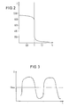
- the two lambda probes 22 and 24 are designed such that they show the characteristic curve profile of the probe voltage U 1 and U 2 shown in FIG. 2 with respect to the air ratio ⁇ .
- the probe voltage U 1 or U 2 is approximately 950 mV when the air ratio ⁇ ⁇ 0.9.
- the characteristic curve shows an approximately parallel course to the high-value axis, ie that even the smallest changes in the air ratio ⁇ lead to large changes in voltage.
- the slope of the characteristic curve decreases again until the branch shown on the right in FIG. 2 from ⁇ > 1.1 runs approximately parallel to the legal value axis.
- a high probe voltage U 1 or U 2 is present at the lambda probe 22 or 24 if the air-fuel mixture burned in the internal combustion engine 12 had a fuel quantity above the stoichiometrically required fuel quantity before the combustion, so that the air ratio ⁇ ⁇ 1.
- the characteristic curve shows an extremely low probe voltage.
- the air ratio ⁇ is approximately 1, an abrupt change in the probe voltage occurs.
- the first lambda probe 22 detects the oxygen content of the exhaust gas of the internal combustion engine 12 immediately upstream of the catalytic converter 18 and passes the detected oxygen concentration on to the engine controller 26 as the first probe voltage U 1 .
- the exhaust gas continues to flow through the catalytic converter 18, is catalyzed in it and finally flows into the central silencer 20.
- the exhaust gas catalyzed by the catalytic converter 18 is detected by the second lambda probe 24, which determines the oxygen content of the catalyzed exhaust gas and transmits it to the second sensor voltage U 2 Engine control 26 forwards.
- the engine controller 26 determines, based on the first probe voltage U 1, the air-fuel ratio to be set in a known manner from a map in which different operating conditions of the engine based on the air ratio ⁇ are stored. Since, for example, due to aging processes, insufficient combustion of the internal combustion engine 12 and the like, the air-fuel ratio determined by the engine controller 26 on the basis of the first probe voltage U 1 can deviate from the desired stoichiometric air-fuel ratio, the second probe voltage is used U 2 checks the previously set air-fuel ratio and adjusts if necessary. In accordance with the air-fuel ratio determined in this way, the injection system 28 is now controlled, which supplies the internal combustion engine 12 with the previously set amount of fuel and air.
- FIG. 3 shows the course of the probe voltage U 1 over a longer period of time, the line running parallel to the time axis defining a switching point U bias .
- the air-fuel ratio is regulated in accordance with the curve shown in FIG. 3, so that the first probe voltage U 1 exhibits an approximately sinusoidal curve around the switching point U bias .
- the previously described closed loop operating mode can no longer be maintained. If the motor vehicle is driven downhill, for example, with a low gear, the internal combustion engine 12 should work as a so-called "engine brake". For this purpose, an air-fuel mixture containing a very high proportion of air is supplied to the internal combustion engine 12. Since the engine controller 26 would attempt to set the air / fuel mixture to a stoichiometric mass ratio in the closed-loop operating mode of the combustion mode 12, this would run counter to the braking function of the internal combustion engine 12.
- the internal combustion engine 12 is operated in such a case in the so-called open-loop operating mode, in which the engine controller 26 sets an air-fuel ratio of the mixture that differs from the stoichiometric mass ratio in accordance with stored data.
- the two lambda probes 22 and 24 record the oxygen content of the exhaust gas, but the determined probe voltages U 1 and U 2 are not used directly to set the air-fuel ratio of the mixture.
- the catalytic converter 18 is usually designed in such a way that that a predetermined amount of oxygen is stored in the catalyst 18 is a predetermined percentage of the maximum in the catalyst 18 corresponds to the amount of oxygen to be stored, provided the conversion rate of the catalyst 18 has not already been removed by aging processes Has.
- the exhaust gas flows through the catalytic converter 18 Hydrocarbon molecules and the carbon monoxide molecules through the Oxygen stored in the catalyst is oxidized, while not with Oxygen occupied the surface sections of the catalyst 18 Reduce nitrogen oxides and store the oxygen.
- closed loop mode of the internal combustion engine 12 prevails in the catalytic converter 18 a balance between the oxidation and reduction reactions, so that the exhaust gases catalyze according to the legal requirements can be, if at least approximately in the internal combustion engine 12 stoichiometric air-fuel mixture is burned.
- the table below shows the test results of a Test cycle of the according to the specifications of the MVEG (Motor Vehicle Emission Group) of the European Union. In this series of experiments a total of four city cycles (supercycles) driven at which the maximum speed is about 50 km / h.
- the average total turnover rate of catalyst 18 (about 97% each) during a normal city cycle or overland cycle compared to the average turnover rate, which the catalyst 18 in a short cycle immediately after Open-loop operation, in which the internal combustion engine with a Speed of about 35 km / h or 50 km / h was operated.
- FIG. 4 shows a diagram in which the probe voltages are plotted over time. If the arrangement 10 is operated in a conventional manner, the entire control takes about 70 seconds to function properly again. While the probe voltage U 1 of the first lambda probe 22 oscillates around the switching point U bias , the second probe voltage U 2 of the second lambda probe 24 shows very low values which indicate to the engine control 26 that the oxygen content in the exhaust gas is too high, so that the engine control 26 has a correspondingly richer value Mixture sets what would not be required per se. In order to avoid this, the method according to the invention described below with reference to FIG. 5 is used, the proper operation of the catalytic converter being possible again in a comparatively short time.
- the engine controller 26 continuously checks in a step S 101 whether the internal combustion engine 12 is operated from an open-loop operating mode in a subsequent closed-loop operating mode. If this is not the case, engine controller 26 returns to its main routine (out), in which it adjusts the air-fuel ratio in a conventional manner, for example. In contrast, if the internal combustion engine 12 was previously operated in an open-loop operating mode while it is subsequently operated in a closed-loop operating mode, a counter is activated in a subsequent document S 102, which counts a predetermined time period t 1 .
- step S 201 the current value of the counter t is compared with the predetermined time t 1 . If the current time t is below the predetermined time period ti, the engine control 26 proceeds to step S 202.
- step S 202 it is checked whether the current probe voltage U 2 of the second lambda probe 24 is below a minimum threshold value U min , ie in step S 202 it is checked whether the oxygen concentration detected by the second lambda probe 24 is above or below a predetermined oxygen concentration. If the oxygen concentration in the exhaust gas is above the threshold value, the second probe voltage U 2 is below the minimum permissible voltage value U min . If, on the other hand, the oxygen concentration is below the threshold value, the second probe voltage U 2 is above the minimum permissible threshold value. In the exemplary embodiment shown, the threshold value U min is approximately 100 mV.
- step S 202 If it is detected in step S 202 that the second probe voltage U 2 is above the minimum permissible threshold value U min , the control returns to step S 201 and checks whether the time t currently counted by the counter corresponds to the predetermined time period t 1 . This process is repeated until either it is detected in step S 201 that the current time t corresponds to the predetermined time period t 1 , or it is determined in step S 202 that the second probe voltage U 2 falls below the minimum permissible threshold value U min .
- step S 301 If the current time t counted by the counter corresponds to the predetermined time period t 1 , the control proceeds to step S 301. If, on the other hand, the second probe voltage U 2 is below the minimum permissible threshold value U min , the engine control 26 continues with step S 203.
- step S 203 the engine controller 26 deactivates the readjustment function, so that during the closed-loop operating mode of the internal combustion engine 12, the air / fuel mixture is only adjusted based on the first probe voltage U 1 of the first lambda probe 22 upstream of the catalytic converter 18. while the second probe voltage U 2 is not taken into account when setting the mixture.
- the engine control unit 26 jumps to step S 301.
- the engine control unit 26 therefore checked in steps S 201 to S 203 whether the oxygen content contained in the exhaust gas exceeds a value that is correct Regulation of the air-fuel ratio of the mixture is hampered by the engine control 26, or whether the oxygen content in the exhaust gas has such a low value that the engine control 26 can determine the mixture on the basis of both probe voltages U 1 and U 2 . In this way, it is ensured that the readjustment is only deactivated when the oxygen content in the catalytic converter 18 has risen so high due to the previous mode of operation in the open-loop operation of the internal combustion engine 12 that during the subsequent closed-loop operation of the internal combustion engine 12 a proper setting of the mixture would not be possible.
- step S 301 the engine controller 26 checks whether the readjustment has been deactivated or not. If the readjustment has not been deactivated, the engine control 26 returns to its main routine. If, on the other hand, it is determined in step S 301 that the readjustment has been deactivated, the engine control 26 continues with step S 302. In step S 302 it is checked whether the switching point U bias currently set by the engine controller 26 is below a lowest permissible switching point U DFCO of approximately 609 mV. The current switching point U bias is usually around 482 mV. Nevertheless, it is possible that the current switching point already has a higher value due to a previous setting.
- the predetermined switching point U DFCO is approximately 609 mV, so that if this predetermined switching point were used, the engine control 26 would set a rich air-fuel mixture which contained a fuel quantity which was above the stoichiometrically required amount.
- step S 302 determines in step S 302 that the current switching point U bias is greater than or equal to the predetermined switching point U DFCO . If the engine controller 26 determines in step S 302 that the current switching point U bias is greater than or equal to the predetermined switching point U DFCO , the engine controller 26 jumps to step S 401. On the other hand, the engine controller 26 determines in step S 302 that the current switching point U bias is below the predetermined switching point U DFCO , it jumps to step S 303, in which the value of the current switching point U bias is set to the value of the predetermined switching point U DFCO . The engine control 26 then jumps to step S 401. In steps S 301 to S 303, the switching point at which the engine control 26 regulates the mixture based on the first probe voltage U 1 is increased, so that the mixture as a whole has a higher fuel content .
- step S 401 the motor controller 26 now checks whether the second probe voltage U 2 is above a maximum permissible threshold value, which in the present case corresponds to approximately 501 mV. In other words, the engine controller 26 checks in step S 401 whether the oxygen concentration in the exhaust gas has already decreased after catalyzing to such an extent that proper regulation is possible again.
- step S 402. the counter is reactivated and in step S 403 the current time t is compared with a second time period t 2 until the current value t of the counter corresponds to the predetermined time period t 2 corresponds. If this is the case, the engine control 26 jumps to step S 404, in which the readjustment is activated again. Control then jumps from step S 404 to its main routine. In steps S 401 and S 404 it is checked whether the oxygen stored in the catalytic converter 18 has reached such a low level that proper readjustment is possible again with the aid of the second probe voltage U 2 .
- the engine controller 26 detects that the internal combustion engine 12 is again operated in a closed loop operating mode after an open-loop operating mode, the engine controller 26 checks in steps S 201 to S 203 whether the oxygen concentration in the exhaust gas after the catalytic converter 18 has reached such a high value that proper readjustment using the second probe voltage U 2 is no longer possible. If this is the case, the readjustment is deactivated. The current switching point U bias is then raised to a predetermined switching point U DFCO in steps S 302 and S 303, as shown in FIG. 4.
- the motor controller 26 continuously checks in step S 401 whether the second probe voltage U 2 corresponds to the maximum permissible threshold value U max . In the diagram shown in FIG. 4, this is the case as soon as the second probe voltage U 2 has reached a value of 501 mV. Subsequently, the readjustment that takes place with the aid of the second probe voltage U 2 is reactivated and the predetermined switching point U DFCO is reset to the current switching point U bias in a step that is not shown.
- the conversion rates of the catalyst 18 were determined for 30 seconds during a closed-loop operation at a speed of approximately 50 km / h, which followed an open-loop operation of the internal combustion engine 12 at a speed of 70 km / h .
- the various conversion rates in Table 2 show that if the readjustment is deactivated and the switching point U bias is simultaneously increased to the higher U DFCO value, the conversion rates of the catalyst 18 can be significantly improved.
- the method according to the invention ensures that the Catalyst 18 in a shorter time by deactivating the readjustment and raising the switching point of the first lambda probe 22 the catalyst 18 reaches its maximum conversion rates faster.
- the catalyst can have a lower conversion rate Have capacity than when using a conventional control method without deactivating the readjustment since the catalytic converter when using the method according to the invention no longer has a accordingly increased storage capacity for the resulting oxygen must be designed.
Abstract
Description
Die Erfindung betrifft ein Verfahren zum Einstellen des Luft-Kraftstoff-Verhältnisses bei einem Verbrennungsmotor, dessen Abgase einem Katalysator zugeführt werden, wobei bei dem Verfahren von einer Motorsteuerung das Signal eines in Strömungsrichtung des Abgases gesehen vor dem Katalysator angeordneten ersten Abgassensors und das Signal eines in Strömungsrichtung gesehen nach dem Katalysator angeordneten zweiten Abgassensors erfaßt wird, die Motorsteuerung während eines Closed-Loop-Betriebsmodus des Verbrennungsmotors basierend auf dem Signal des ersten Abgassensors das Luft-Kraftstoff-Verhältnis des dem Verbrennungsmotor zugeführten Luft-Kraftstoff-Gemisches auf ein vorgegebenes Luft-Kraftstoff-Verhältnis einstellt, und die Motorsteuerung bei einer Abweichung des eingestellten Luft-Kraftstoff-Verhältnisses von einem stöchiometrischen Massenverhältnis das Signal des zweiten Abgassensors zur Nachregelung des eingestellten Luft-Kraftstoff-Verhältnisses auf das stöchiometrische Massenverhältnis verwendet.The invention relates to a method for adjusting the air-fuel ratio in an internal combustion engine, the exhaust gases of a catalyst are supplied, with the method of an engine control the signal of a seen in the flow direction of the exhaust gas before Catalyst arranged first exhaust gas sensor and the signal of an in Direction of flow seen after the catalyst arranged second Exhaust gas sensor is detected, the engine control during a closed-loop operating mode of the internal combustion engine based on the signal of the first exhaust gas sensor the air-fuel ratio of the internal combustion engine supplied air-fuel mixture to a predetermined Air-fuel ratio sets, and the engine control in the event of a deviation the set air-fuel ratio of one stoichiometric mass ratio the signal of the second exhaust gas sensor to readjust the set air-fuel ratio to the stoichiometric mass ratio used.
Durch den Einsatz geregelter Katalysatoren bei Verbrennungsmotoren können mit den heute verfügbaren Zünd- und Einspritzsystemen sehr niedrige Abgaswerte erreicht werden. So hat der Katalysator unter anderem die Eigenschaft, Kohlenwasserstoffe (HC), Kohlenmonoxide (CO) und Stickoxide (Nox) bis zu mehr als 90% abzubauen, falls der Verbrennungsmotor in einem sehr engen Streubereich um das stöchiometrische Luft-Kraftstoff-Verhältnis betrieben wird, bei dem das Luftverhältnis λ = 1 ist, Das Luftverhältnis λ ist dabei als Verhältnis aus zugeführter Luftmasse bezogen auf den theoretischen Luftbedarf definiert.Through the use of regulated catalytic converters in internal combustion engines, very low exhaust gas values can be achieved with the ignition and injection systems available today. Among other things, the catalytic converter has the property of reducing hydrocarbons (HC), carbon monoxides (CO) and nitrogen oxides (No x ) by more than 90% if the internal combustion engine is operated in a very narrow range around the stoichiometric air-fuel ratio , in which the air ratio λ = 1, the air ratio λ is defined as the ratio of the supplied air mass based on the theoretical air requirement.
Mit Hilfe des eingangs genannten Verfahrens kann während des Closed-Loop-Betriebsmodus des Verbrennungsmotors, bei dem das Luft-Kraftstoff-Verhältnis des zugeführten Luft-Kraftstoff-Gemisches basierend auf dem Signal des ersten Abgassensors eingestellt wird, bei Abweichung dieses eingestellten Luft-Kraftstoff-Verhältnisses von dem zuvor beschriebenen stöchiometrischen Massenverhältnis das Signal des zweiten Abgassensors verwendet werden, um das eingestellte Luft-Kraftstoff-Verhältnis auf das stöchiometrische Massenverhältnis nachzuregeln.With the help of the method mentioned at the beginning, during the closed-loop operating mode of the internal combustion engine, in which the air-fuel ratio of the supplied air-fuel mixture based on the signal of the first exhaust gas sensor is set, if this deviates set air-fuel ratio from that previously described stoichiometric mass ratio the signal of the second exhaust gas sensor used to set the air-fuel ratio to adjust to the stoichiometric mass ratio.
Beim sogenannten Open-Loop-Betriebsmodus des Verbrennungsmotors, bei dem die Motorsteuerung auch eine vom stöchiometrischen Massenverhältnis abweichende Einstellung des Luft-Kraftstoff-Verhältnisses zuläßt, beispielsweise während einer Bergabfahrt des Kraftfahrzeuges oder während der Drosselung der Kraftstoffzufuhr bei fahrendem Kraftfahrzeug, ist es erwünscht, daß das eingestellte Luft-Kraftstoff-Verhältnis vom stöchiometrischen Massenverhältnis abweicht, damit der Verbrennungsmotor das Fahrzeug bremst. Damit die Leistung des Katalysators trotz des nicht auf das stöchiometrische Massenverhältnis eingestellten Luft-Kraftstoff-Gemisches eine ausreichend hohe Umsatzrate besitzt, weist der Katalysator eine entsprechend große Oberfläche auf, damit die Abgase in ausreichendem Maß oxidiert bzw. reduziert werden können.In the so-called open loop operating mode of the internal combustion engine, where the engine control also has a stoichiometric mass ratio allows a different setting of the air-fuel ratio, for example during a downhill descent of the motor vehicle or during the throttling of the fuel supply when the motor vehicle is moving it is desirable that the set air-fuel ratio from stoichiometric mass ratio deviates so that the internal combustion engine the vehicle brakes. So that the performance of the catalyst despite the air / fuel mixture not adjusted to the stoichiometric mass ratio has a sufficiently high turnover rate, the A correspondingly large surface area so that the exhaust gases in can be oxidized or reduced to a sufficient extent.
Bei längerem Betrieb des Verbrennungsmotors im Open-Loop-Betriebsmodus besteht jedoch das Problem, daß es beispielsweise bei Verbrennung eines mageren Luft-Kraftstoff-Gemisches, bei dem die dem Motor zugeführte Luftmenge über der stöchiometrisch erforderlichen Luftmenge liegt, zu einer Anreicherung von Sauerstoff im Katalysator kommt, an dessen katalytisch wirksamer Oberfläche sich die Sauerstoffmoleküle ablagern. Durch die Anreicherung des Sauerstoffs im Katalysator ist zwar einerseits die Oxidation der Kohlenmonoxide in Kohlendioxid und die Oxidation der Kohlenwasserstoffe in Kohlendioxid und Wasser verbessert, andererseits ist jedoch eine Reduzierung der Stickoxide nur mehr in vermindertem Maß möglich, da der in den Stickoxiden gebundene Sauerstoff nicht mehr an den Katalysator abgegeben werden kann. Als Folge können während eines einem Open-Loop-Betriebes des Verbrennungsmotors folgenden Closed-Loop-Betriebes die Abgase nur durch Verwendung eines entsprechend groß dimensionierten Katalysators in ausreichendem Maß katalysiert werden.When the internal combustion engine is operated for a longer period in the open-loop operating mode However, there is the problem that it is burned, for example of a lean air-fuel mixture in which the engine amount of air supplied above the stoichiometrically required amount of air is due to an accumulation of oxygen in the catalyst, at the the oxygen molecules are deposited on the catalytically active surface. Due to the enrichment of oxygen in the catalyst, on the one hand the oxidation of carbon monoxides in carbon dioxide and the oxidation which improves hydrocarbons in carbon dioxide and water, on the other hand, however, a reduction in nitrogen oxides is only reduced Measure possible because of the oxygen bound in the nitrogen oxides can no longer be released to the catalyst. As a result, you can during an open loop operation of the internal combustion engine Closed-loop operation only by using an exhaust gas sufficiently large sized catalyst be catalyzed.
Es ist Aufgabe der Erfindung, ein Verfahren zum Einstellen des Luft-Kraftstoff-Verhältnisses bei einem Verbrennungsmotor anzugeben, durch das nach einem Betrieb des Verbrennungsmotors im Open-Loop-Betriebsmodus der Katalysator während des nachfolgenden Betriebes des Verbrennungsmotors im Closed-Loop-Betriebsmodus in verglichen bei dem Einsatz herkömmlicher Verfahren kürzerer Zeit eine ausreichend hohe Umsatzrate aufweist.It is an object of the invention to provide a method for adjusting the air-fuel ratio to indicate in an internal combustion engine by after operating the internal combustion engine in the open loop operating mode the catalytic converter during the subsequent operation of the internal combustion engine in closed-loop mode in comparison when in use conventional processes in a shorter time a sufficiently high turnover rate having.
Die Erfindung löst die Aufgabe durch ein Verfahren mit den Merkmalen
nach Anspruch 1, und insbesondere dadurch, daß nach einem Betrieb des
Verbrennungsmotors in einem Open-Loop-Betriebsmodus, bei dem die
Motorsteuerung auch ein vom stöchiometrischen Massenverhältnis abweichendes
Einstellen des Luft-Kraftstoff-Verhältnisses vornimmt, während
eines nachfolgenden Betriebes des Verbrennungsmotors im Closed-Loop-Betriebsmodus
die Nachregelung des Luft-Kraftstoff-Verhältnisses mit
Hilfe des Signals des zweiten Abgassensors zeitweise deaktiviert werden
kann.The invention solves the problem by a method with the features
according to
Durch den Einsatz des erfindungsgemäßen Verfahrens wird erreicht, daß unmittelbar nach dem Wechseln des Betriebes des Verbrennungsmotors vom Open-Loop-Betriebsmodus in den Closed-Loop-Betriebsmodus die Motorsteuerung das Luft-Kraftstoff-Verhältnis des dem Verbrennungsmotor zuzuführenden Gemisches zeitweise nur auf Grundlage des Signals des ersten Abgassensors einstellt. Folglich wird bei abgeschalteter Nachregelung nur die Zusammensetzung des nicht-katalysierten Abgases vor dem Katalysator für die Bestimmung des Luft-Kraftstoff-Verhältnisses des Gemisches herangezogen, das dem Verbrennungsmotor zugeführt wird, während die Zusammensetzung des katalysierten Abgases bei der Einstellung des Luft-Kraftstoff-Verhältnisses unberücksichtigt bleibt. Auf diese Weise wird vermieden, daß basierend auf eventuell im Katalysator gespeicherten, teilweise katalysierten Zwischenprodukten, wie beispielsweise nach einem Open-Loop-Betrieb des Verbrennungsmotors mit magerem Luft-Kraftstoff-Gemisch im Katalysator gespeicherter Sauerstoff, die vom durch den Katalysator strömenden Abgas mitgerissen werden, der zweite Abgassensor eine Abgaszusammensetzung erfaßt, die nicht den tatsächlichen Betriebsbedingungen des Verbrennungsmotors entspricht. Anderenfalls würde das von der Motorsteuerung einzustellende Luft-Kraftstoff-Verhältnis des dem Verbrennungsmotor zuzuführenden Gemisches auf Grundlage verfälschter Abgaszusammensetzungen bestimmt, die wiederum zu einer ungünstigen Einstellung des Luft-Kraftstoff-Verhältnisses führen würde. Nachdem die Nachregelung zeitweise deaktiviert war, um die im Katalysator gespeicherten Zwischenprodukte zumindest teilweise abzuführen, wird die Nachregelung des Luft-Kraftstoff-Verhältnisses erneut aktiviert, damit die für einen optimalen Betrieb des Verbrennungsmotors und eine möglichst hohe Umsatzrate des Katalysators erforderliche Einstellung des Luft-Kraftstoff-Verhältnisses des Gemisches wieder möglich wird.By using the method according to the invention it is achieved that immediately after changing the operation of the internal combustion engine from the open loop operating mode to the closed loop operating mode Engine control the air-fuel ratio of the internal combustion engine mixture to be supplied temporarily only on the basis of the signal of the first exhaust gas sensor. Consequently, if the readjustment is switched off only the composition of the non-catalyzed exhaust gas the catalyst for determining the air-fuel ratio of the Mixture used, which is fed to the internal combustion engine, while adjusting the composition of the catalyzed exhaust the air-fuel ratio is not taken into account. To this In this way it is avoided that, based on possibly stored in the catalyst, partially catalyzed intermediates, such as after an open-loop operation of the internal combustion engine with a lean Air-fuel mixture oxygen stored in the catalytic converter by the exhaust gas flowing through the catalytic converter, the second Exhaust gas sensor detects an exhaust gas composition that is not the actual one Operating conditions of the internal combustion engine corresponds. Otherwise would be the air-fuel ratio to be set by the engine control of the mixture to be supplied to the internal combustion engine Determined the basis of adulterated exhaust gas compositions, which in turn to an unfavorable setting of the air-fuel ratio would lead. After the readjustment was temporarily deactivated in order to the intermediate products stored in the catalyst at least partially the air-fuel ratio is readjusted again activated so that the optimal operation of the internal combustion engine and the highest possible conversion rate of the catalyst required Adjustment of the air-fuel ratio of the mixture possible again becomes.
Weitere Vorteile der Erfindung ergeben sich aus der nachfolgenden Beschreibung, der Zeichnung sowie den Unteransprüchen.Further advantages of the invention result from the following description, the drawing and the subclaims.
So ist es insbesondere von Vorteil, die Nachregelung des Luft-Kraftstoff-Verhältnisses während des Closed-Loop-Betriebsmodus zeitweise zu deaktivieren, wenn der Verbrennungsmotor während des zuvor erfolgten Open-Loop-Betriebsmodus mit einem mageren Luft-Kraftstoff-Gemisch betrieben wurde, bei dem die zugeführte Luftmenge des Gemisches über der stöchiometrisch erforderlichen Luftmenge lag. Gerade bei der Verbrennung eines mageren Luft-Kraftstoff-Gemisches im Verbrennungsmotor entstehen im Abgas Sauerstoffmoleküle, die sich an der katalytisch wirksamen Schicht des Katalysators ablagern und insbesondere eine Reduktion der Stickoxide in den Abgasen verhindern, während gleichzeitig die Kohlenmonoxide und Kohlenwasserstoffe durch den hohen Sauerstoffgehalt des im Katalysator befindlichen Abgases oxidiert werden. So wurden Versuchsreihen nach den Vorschriften der europäischen MVEG (Motor Vehicle Emission Group) durchgeführt, die als MVEG-B-Test bekannt sind, in denen ermittelt wurde, daß nach einem Betrieb des Verbrennungsmotors im Open-Loop-Betrieb die Stickoxide während des Closed-Loop-Betriebes des Verbrennungsmotors unmittelbar nach dem Open-Loop-Betrieb nur zu etwa 83% umgesetzt werden konnten, während üblicherweise eine Umsatzrate des Katalysators bei Stickoxiden von annähernd 97% erreicht wird. Durch das zeitweise Abschalten der Nachregelung des Luft-Kraftstoff-Verhältnisses wird erreicht, daß der im Abgas enthaltene hohe Sauerstoffgehalt bei der Einstellung des Luft-Kraftstoff-Verhältnisses des dem Verbrennungsmotor zugeführten Gemisches nicht berücksichtigt wird und die Umsatzrate des Katalysators entsprechend zunimmt, da die Motorsteuerung mit Hilfe des Signals des ersten Abgassensors ein zumindest an das stöchiometrische Verhältnis angenähertes Gemisch einstellt. Insbesondere bei dieser zuvor beschriebenen Ausgestaltung des erfindungsgemäßen Verfahrens wird vorgeschlagen, die Nachregelung des Luft-Kraftstoff-Verhältnisses nur dann zu deaktivieren, wenn das vom zweiten Abgassensor an die Motorsteuerung abgegebene Signal einen Wert annimmt, der unter einem vorgegebenen minimalen Schwellenwert liegt. Auf diese Weise wird erreicht, daß wenn der Verbrennungsmotor nur über einen kurzen Zeitraum im Open-Loop-Betriebsmodus gefahren wurde, bei dem sich eine vernachlässigbar kleine Menge an Zwischenprodukten im Katalysator angesammelt hat, die Nachregelung des Luft-Kraftstoff-Verhältnisses dennoch vorgenommen wird.It is particularly advantageous to readjust the air-fuel ratio to deactivate temporarily during the closed loop operating mode, if the internal combustion engine took place during the previous Open loop operating mode with a lean air-fuel mixture was operated, in which the amount of air supplied to the mixture the stoichiometrically required amount of air. Especially when it comes to combustion of a lean air-fuel mixture in the internal combustion engine Oxygen molecules are formed in the exhaust gas, which are catalytically active deposit effective layer of the catalyst and in particular a reduction prevent the nitrogen oxides in the exhaust gases while at the same time the carbon monoxides and hydrocarbons due to the high oxygen content of the exhaust gas in the catalyst are oxidized. So were Test series according to the regulations of the European MVEG (Motor Vehicle Emission Group) performed known as the MVEG-B test are in which it was determined that after operation of the internal combustion engine in open loop mode, the nitrogen oxides during closed loop mode of the internal combustion engine immediately after the open loop operation only about 83% could be implemented, while usually a conversion rate of the catalyst for nitrogen oxides of approximately 97% is reached. By temporarily switching off the readjustment The air-fuel ratio is achieved in that in the exhaust gas contained high oxygen content when setting the air-fuel ratio of the mixture supplied to the internal combustion engine is taken into account and the conversion rate of the catalyst accordingly increases because the engine control system uses the signal from the first exhaust gas sensor one that is at least approximated to the stoichiometric ratio Mixture. In particular with this embodiment described above of the inventive method is proposed that Only deactivate readjustment of the air-fuel ratio if the output from the second exhaust gas sensor to the engine control Signal assumes a value that is below a predetermined minimum Threshold is. In this way it is achieved that when the internal combustion engine only for a short time in open loop mode was driven, in which a negligibly small amount Intermediates accumulated in the catalyst, the readjustment of the air-fuel ratio is nevertheless made.
Des weiteren wird bei diesem Verfahren vorgeschlagen, nur innerhalb eines vorgegebenen ersten Zeitraums zu überprüfen, ob der Wert des vom zweiten Abgassensor abgegebenen Signals unter dem vorgegebenen minimalen Schwellenwert liegt. Da das Abgas eine beispielsweise von der Motordrehzahl abhängige Zeit benötigt, um vom Verbrennungsmotor durch den Katalysator bis zum zweiten Abgassensor zu gelangen, wird auf diese Weise sichergestellt, daß bei der Beurteilung, ob die Nachregelung abgeschaltet werden soll, auch tatsächlich die Zusammensetzung des Abgases ermittelt wird, das unmittelbar vor dem Umschalten von dem Open-Loop-Betrieb des Verbrennungsmotors in den Closed-Loop-Betrieb in die Zylinder des Verbrennungsmotors eingeströmt ist. Der vorgegebene erste Zeitraum wird hierzu als fester Wert vorgegeben, der beispielsweise einem Zeitraum entspricht, den das Abgas bei Betrieb des Verbrennungsmotors im Leerlauf benötigt, um vom Verbrennungsmotor durch den Katalysator zum zweiten Abgassensor zu gelangen.Furthermore, this method proposes only within one predetermined first period to check whether the value of the second exhaust gas sensor signal below the predetermined minimum Threshold is. Because the exhaust gas is an example of the engine speed dependent time taken by the internal combustion engine the catalyst to get to the second exhaust gas sensor is on this Way ensured that when assessing whether the readjustment is switched off should actually be the composition of the exhaust gas is determined that immediately before switching from the open loop mode of the internal combustion engine in the closed-loop mode in the cylinders of the internal combustion engine has flowed in. The specified first period is specified as a fixed value for this, for example one Corresponds to the period of time that the exhaust gas during operation of the internal combustion engine at idle required by the internal combustion engine through the catalyst to get to the second exhaust gas sensor.
Damit sichergestellt wird, daß die Nachregelung des Luft-Kraftstoff-Verhältnisses nur so kurz wie möglich deaktiviert ist, wird vorgeschlagen die Nachregelung dann wieder aufzunehmen, wenn das vom zweiten Abgassensor an die Motorsteuerung abgegebene Signal einen vorgegebenen maximalen Schwellenwert überschreitet. Dabei ist es ferner von Vorteil, wenn, nachdem das vom zweiten Abgassensor an die Motorsteuerung abgegebene Signal den vorgegebenen maximalen Schwellenwert überschritten hat, die Nachregelung des Luft-Kraftstoff-Verhältnisses nach Ablauf einer vorgegebenen zweiten Zeitdauer wieder aufzunehmen, damit ein sanfter Übergang beim nachfolgenden Aktivieren der Nachregelung ermöglicht werden kann.This ensures that the readjustment of the air-fuel ratio is deactivated only as briefly as possible, it is proposed Readjustment must then be resumed when the second exhaust gas sensor signal given to the engine control a predetermined maximum Threshold exceeded. It is also an advantage if, after that from the second exhaust gas sensor to the engine control Signal exceeded the specified maximum threshold has the readjustment of the air-fuel ratio after expiration a predetermined second time period to resume enables a smooth transition when subsequently activating the readjustment can be.
Bei einer bevorzugten Weiterbildung des Verfahrens definiert die Motorsteuerung zur Beurteilung, ob das Luft-Kraftstoff-Gemisch mit Luft oder Kraftstoff angereichert werden muß, einen aktuellen Schaltpunkt, bei dessen Überschreiten durch den Wert des Signals des ersten Abgassensors das Gemisch mit Luft und bei dessen Unterschreiten das Gemisch mit Kraftstoff angereichert wird. Auf diese Weise arbeitet der erste Abgassensor quasi als digitaler Sensor mit einem festen Schaltpunkt, wodurch eine besonders schnell ansprechende Regelung des Luft-Kraftstoff-Verhältnisses im Gemisch möglich ist. In a preferred development of the method, the engine control defines to assess whether the air-fuel mixture with air or Fuel must be enriched at a current switching point at which Exceeded by the value of the signal from the first exhaust gas sensor the mixture with air and when it falls below the mixture with Fuel is enriched. The first exhaust gas sensor works in this way quasi as a digital sensor with a fixed switching point, which means a Particularly responsive regulation of the air-fuel ratio in a mixture is possible.
Bei dieser Weiterbildung des Verfahrens ist es besonders von Vorteil, den aktuellen Schaltpunkt von der Motorsteuerung auf einen vorgegebenen Schaltpunkt einzustellen, sobald die Nachregelung des Luft-Kraftstoff-Verhältnisses deaktiviert wird. Der vorgegebene Schaltpunkt ist dabei so gewählt, daß dem Verbrennungsmotor ein mageres Luft-Kraftstoff-Gemisch bzw. ein fettes Luft-Kraftstoff-Gemisch, bei dem die zugeführte Kraftstoffmenge über der stöchiometrisch erforderlichen Kraftstoffmenge liegt, zugeführt wird, damit das aus dem Verbrennungsmotor geförderte Abgas den Katalysator von den in ihm gespeicherten Zwischenprodukten reinigt bzw. diese Zwischenprodukte kompensiert.In this development of the method, it is particularly advantageous that the current switching point from the engine control to a predetermined Set the switching point as soon as the readjustment of the air-fuel ratio is deactivated. The default switching point is like this chosen that the internal combustion engine a lean air-fuel mixture or a rich air-fuel mixture in which the supplied Amount of fuel above the stoichiometrically required amount of fuel lies, is supplied so that the conveyed from the internal combustion engine Exhaust the catalyst from the intermediates stored in it cleans or compensates for these intermediates.
Als Abgassensoren werden vorzugsweise Lambdasonden verwendet, an denen in Abhängigkeit vom Sauerstoffgehalt des Abgases jeweils eine Spannung anliegt, die von der Motorsteuerung zum Bestimmen des Luft-Kraftstoff-Verhältnisses abgegriffen wird, da Lambdasonden ein quasi digitales Verhalten zeigen, welches für die Bestimmung des Luft-Kraftstoff-Verhältnisses durch die Motorsteuerung besonders geeignet ist.Lambda sensors are preferably used as exhaust gas sensors depending on the oxygen content of the exhaust gas Voltage applied by the engine controller to determine the air-fuel ratio is tapped because lambda sensors are a quasi digital Show behavior which for determining the air-fuel ratio is particularly suitable due to the motor control.
Bei Verwendung von Lambdasonden wird der aktuelle Schaltpunkt, bei dessen Überschreiten das Gemisch mit Luft bzw. bei dessen Unterschreiten das Gemisch mit Kraftstoff angereichert wird, durch einen Spannungswert definiert, der von der Motorsteuerung mit der abgegriffenen Spannung der ersten Lambdasonde verglichen wird.When using lambda sensors, the current switching point is at its exceeding the mixture with air or falling below it the mixture is enriched with fuel by a voltage value defined by the motor control with the tapped Voltage of the first lambda probe is compared.
Nachfolgend wird die Erfindung anhand eines Ausführungsbeispieles unter Bezugnahme auf die Zeichnung näher erläutert. Darin zeigen:
- Fig. 1
- eine schematische Darstellung einer Anordnung, die nach dem erfindungsgemäßen Verfahren einen Verbrennungsmotor regelt,
- Fig. 2
- ein Diagramm, in dem die Spannungskennlinie einer Lambdasonde bezogen auf das Luftverhältnis λ dargestellt ist,
- Fig. 3
- ein Diagramm, in dem die Sondenspannung der Lambdasonde bezogen auf die Zeit dargestellt ist,
- Fig. 4
- ein Diagramm, in dem die Verläufe der Sondenspannungen der beiden Lambdasonden bezogen auf die Zeit mit und ohne Deaktivierung der Nachregelung gezeigt sind, und
- Fig. 5
- ein Ablaufdiagramm des erfindungsgemäßen Verfahrens.
- Fig. 1
- 1 shows a schematic representation of an arrangement which controls an internal combustion engine according to the method according to the invention,
- Fig. 2
- 1 shows a diagram in which the voltage characteristic curve of a lambda sensor is shown in relation to the air ratio λ,
- Fig. 3
- 1 shows a diagram in which the probe voltage of the lambda probe is shown in relation to time,
- Fig. 4
- a diagram in which the courses of the probe voltages of the two lambda probes are shown in relation to the time with and without deactivation of the readjustment, and
- Fig. 5
- a flowchart of the method according to the invention.
In Fig. 1 ist in schematischer Darstellung eine Anordnung 10 zum Regeln
und Steuern eines Verbrennungsmotors 12 eines nicht dargestellten
Kraftfahrzeuges gezeigt. Der Auslaß des Verbrennungsmotors 12 steht mit
einem Vorschalldämpfer 14, einer Abgasanlage 16 in Strömungsverbindung.
Der Vorschalldämpfer 14 ist seinerseits mit einem Katalysator 18
verbunden, der in einen Mittelschalldämpfer 20 übergeht. An den Mittelschalldämpfer
20 schließt sich ein nicht dargestellter Nachschalldämpfer
der Abgasanlage 16 an. In Strömungsrichtung des Abgases gesehen vor
dem Katalysator 18 ist nahe diesem in dem Verbindungsrohr des Vorschalldämpfers
14 zum Katalysator 18 eine erste Lambdasonde 22 angeordnet,
die mit ihrem Sondenkopf in das Verbindungsrohr ragt. In Strömungsrichtung
des Abgases gesehen nach dem Katalysator 18 ist eine
zweite Lambdasonde 24 positioniert, die mit ihrem Sondenabschnitt in
das Verbindungsrohr des Katalysators 18 zum Mittelschalldämpfer 20
ragt.In Fig. 1 is an
Die beiden Lambdasonden 22 und 24 sind elektrisch leitend mit einer
Motorsteuerung 26 verbunden, die ihrerseits mit einer Einspritzanlage 28
des Verbrennungsmotors 12 elektrisch leitend verbunden ist. Der Einspritzanlage
28 wird durch eine Kraftstoffleitung 30 Kraftstoff und durch
einen Ansaugstutzen 32 Luft zugeführt. Die Einspritzanlage 28 erzeugt,
geregelt durch die Motorsteuerung 26, ein entsprechend den Vorgaben der
Motorsteuerung 26 eingestelltes Luft-Kraftstoff-Gemisch, das in die einzelnen
Zylinder des Verbrennungsmotors 12 in bekannterweise eingespritzt
wird.The two lambda probes 22 and 24 are electrically conductive with one
Während des Betriebes des Verbrennungsmotors 12 erfassen die beiden
Lambdasonden 22 und 24 den Sauerstoffgehalt des Abgases in Strömungsrichtung
gesehen vor bzw. nach dem Katalysator 18. Die Arbeitsweise
der beiden identisch ausgebildeten Lambdasonden 22 und 24 wird
nachfolgend unter Bezugnahme auf die Fig. 2 näher erläutert. Die beiden
Lambdasonden 22 und 24 arbeiten nach dem Prinzip einer galvanischen
Sauerstoff-Konzentrationszelle, wobei die Sauerstoffkonzentration im Abgas
mit der Sauerstoffkonzentration der Umgebungsluft verglichen wird.
Unterscheidet sich die Sauerstoffkonzentration des Abgases von der Sauerstoffkonzentration
der Luft, liegt an der Lambdasonde 22 bzw. 24 eine
dem Konzentrationsunterschied entsprechende Spannung U1 bzw. U2 an.
Die beiden Lambdasonden 22 und 24 sind so ausgebildet, daß sie den in
Fig. 2 gezeigten Kennlinienverlauf der Sondenspannung U1 bzw. U2 bezogen
auf das Luftverhältnis λ zeigen. During operation of the
Wie Fig. 2 zeigt, liegt die Sondenspannung U1 bzw. U2 bei etwa 950 mV,
wenn das Luftverhältnis λ < 0,9 ist. Bei einem Luftverhältnis λ von einem
Wert um den Betrag 1 zeigt die Kennlinie einen annähernd parallelen
Verlauf zur Hochwertachse, d. h. daß bereits kleinste Änderungen des
Luftverhältnisses λ zu großen Spannungsänderungen führen. Mit weiter
zunehmendem Luftverhältnis λ nimmt die Steigung der Kennlinie wieder
ab, bis der in Fig. 2 rechts dargestellte Zweig ab λ > 1,1 annähernd parallel
zur Rechtswertachse verläuft. Mit anderen Worten liegt an der
Lambdasonde 22 bzw. 24 eine hohe Sondenspannung U1 bzw. U2 an,
wenn das im Verbrennungsmotor 12 verbrannte Luft-Kraftstoff-Gemisch
vor der Verbrennung eine über der stöchiometrisch erforderlichen Kraftstoffmenge
liegende Kraftstoffmenge aufwies, so daß das Luftverhältnis
λ < 1 ist. Wurde dagegen der Verbrennungsmotor 12 mit einem mageren
Luft-Kraftstoff-Gemisch betrieben, bei dem die zugeführte Luftmenge über
der stöchiometrisch erforderlichen Luftmenge lag, zeigt die Kennlinie eine
äußerst geringe Sondenspannung. Liegt dagegen das Luftverhältnis λ annähernd
bei dem Wert 1, tritt eine schlagartige Änderung der Sondenspannung
auf. Mit Hilfe dieses als quasi digital zu bezeichnenden Verhaltens
der Lambdasonden 22 und 24 ist eine sehr genaue Einstellung des
Luft-Kraftstoff-Verhältnisses des Gemisches möglich, da bereits kleinste
Änderungen des Luftverhältnisses λ zu großen Spannungsänderungen der
Sondenspannungen U1 und U2 führen.As shown in FIG. 2, the probe voltage U 1 or U 2 is approximately 950 mV when the air ratio λ <0.9. With an air ratio λ of a value by the
Nachfolgend wird unter Bezugnahme auf Fig. 3 die Arbeitsweise der Anordnung
10 näher erläutert. Wird der Verbrennungsmotor 12 in einem
Closed-Loop-Betriebsmodus betrieben, erfaßt die erste Lambdasonde 22
den Sauerstoffgehalt des Abgases des Verbrennungsmotors 12 unmittelbar
vor dem Katalysator 18 und gibt die erfaßte Sauerstoffkonzentration
als erste Sondenspannung U1 an die Motorsteuerung 26 weiter. Das Abgas
strömt weiter durch den Katalysator 18, wird in diesem katalysiert und
strömt schließlich in den Mittelschalldämpfer 20. Das vom Katalysator 18
katalysierte Abgas wird von der zweiten Lambdasonde 24 erfaßt, die den
Sauerstoffgehalt des katalysierten Abgases ermittelt und als zweite Sondenspannung
U2 an die Motorsteuerung 26 weiterleitet. Die Motorsteuerung
26 ermittelt basierend auf der ersten Sondenspannung U1 das einzustellende
Luft-Kraftstoff-Verhältnis in bekannterweise aus einem Kennfeld,
in dem unterschiedliche Betriebsbedingungen des Motors bezogen auf das
Luftverhältnis λ abgespeichert sind. Da beispielsweise, aufgrund von Alterungsprozessen,
unzureichender Verbrennung des Verbrennungsmotors
12 und ähnlichem, das von der Motorsteuerung 26 auf Grundlage der ersten
Sondenspannung U1 ermittelte Luft-Kraftstoff-Verhältnis vom gewünschten
stöchiometrischen Luft-Kraftstoff-Verhältnis abweichen kann,
wird mit Hilfe der zweiten Sondenspannung U2 das zuvor eingestellte Luft-Kraftstoff-Verhältnis
kontrolliert und gegebenenfalls nachgeregelt. Entsprechend
dem so ermittelten Luft-Kraftstoff-Verhältnis wird nun die Einspritzanlage
28 angesteuert, die dem Verbrennungsmotor 12 die zuvor
eingestellte Menge an Kraftstoff und Luft zuführt.The mode of operation of the
In Fig. 3 ist der Verlauf der Sondenspannung U1 über einen längeren Zeitraum
dargestellt, wobei die parallel zur Zeitachse verlaufende Linie einen
Schaltpunkt Ubias definiert. Während des Closed-Loop-Betriebsmodus des
Verbrennungsmotors 12 wird das Luft-Kraftstoff-Verhältnis entsprechend
dem in Fig. 3 gezeigten Verlauf geregelt, so daß die erste Sondenspannung
U1 einen etwa sinusförmigen Verlauf um den Schaltpunkt Ubias zeigt. 3 shows the course of the probe voltage U 1 over a longer period of time, the line running parallel to the time axis defining a switching point U bias . During the closed-loop operating mode of the
Bei bestimmten Betriebsbedingungen des Verbrennungsmotors 12 kann
der zuvor beschriebene Closed-Loop-Betriebsmodus nicht mehr eingehalten
werden. Wird das Kraftfahrzeug beispielsweise mit einem niedrig eingelegten
Gang bergab gefahren, soll der Verbrennungsmotor 12 als sogenannte
"Motorbremse" arbeiten. Zu diesem Zweck wird dem Verbrennungsmotor
12 ein Luft-Kraftstoff-Gemisch zugeführt, das einen sehr hohen
Luftanteil enthält. Da die Motorsteuerung 26 im Closed-Loop-Betriebsmodus
des Verbrennungsmodus 12 versuchen würde, das Luft-Kraftstoff-Gemisch
auf ein stöchiometrisches Massenverhältnis einzustellen,
würde dies der Bremsfunktion des Verbrennungsmotors 12 zuwiderlaufen.
Aus diesem Grund wird der Verbrennungsmotor 12 in einem derartigen
Fall im sogenannten Open-Loop-Betriebsmodus gefahren, bei dem
die Motorsteuerung 26 entsprechend abgespeicherter Daten ein vom stöchiometrischen
Massenverhältnis abweichendes Luft-Kraftstoff-Verhältnis
des Gemisches einstellt. In diesem Open-Loop-Betriebsmodus erfassen die
beiden Lambdasonden 22 und 24 zwar den Sauerstoffgehalt des Abgases,
die ermittelten Sondenspannungen U1 und U2 werden jedoch nicht unmittelbar
zur Einstellung des Luft-Kraftstoff-Verhältnisses des Gemisches
verwendet.Under certain operating conditions of the
Insbesondere während des Betriebes des Verbrennungsmotors 12 mit einem
mageren Luft-Kraftstoff-Gemisch steigt der Sauerstoffgehalt im Abgas
an, wodurch das Problem besteht, daß der Sauerstoffüberschuß im Abgas
sich an der katalytisch wirksamen Schicht des Katalysators 18 ablagert
und dessen Funktion zumindest kurzfristig nachteilig beeinflußt, wie
nachfolgend erläutert wird. Üblicherweise ist der Katalysator 18 so ausgelegt,
daß eine vorgegebene Menge an Sauerstoff im Katalysator 18 gespeichert
ist, die einem vorgegebenen Prozentsatz der maximal im Katalysator
18 zu speichernden Sauerstoffmenge entspricht, sofern die Umsatzrate
des Katalysators 18 nicht durch Alterungsprozesse bereits abgenommen
hat. Strömt nun das Abgas durch den Katalysator 18 werden die
Kohlenwasserstoffmoleküle und die Kohlenmonoxidmoleküle durch den
im Katalysator gespeicherten Sauerstoff oxidiert, während die nicht mit
Sauerstoff belegten Oberflächenabschnitte des Katalysators 18 die
Stickoxide reduzieren und den Sauerstoff speichern. Während des Closed-Loop-Betriebsmodus
des Verbrennungsmotors 12 herrscht im Katalysator
18 ein Gleichgewicht zwischen den Oxidations- und Reduktionsreaktionen,
so daß die Abgase entsprechend den gesetzlichen Vorgaben katalysiert
werden können, sofern im Verbrennungsmotor 12 ein zumindest annähernd
stöchiometrisches Luft-Kraftstoff-Gemisch verbrannt wird.In particular during the operation of the
Wird nun der Verbrennungsmotor 12 über einen längeren Zeitraum mit
einem mageren Luft-Kraftstoff-Gemisch betrieben, wird ein Großteil der
katalytisch wirksamen Oberfläche des Katalysators 18 mit Sauerstoffmolekülen
belegt, so daß eine ausreichende Reduktion der Stickoxide im
Katalysator 18 nur mehr eingeschränkt möglich ist. Wird nun nach einem
Open-Loop-Betrieb der Verbrennungsmotor wieder im Closed-Loop-Betriebsmodus
gefahren, bei dem ein stöchiometrisch eingestelltes Luft-Kraftstoff-Verhältnis
verbrannt wird, kommt es zu einer unzureichenden
Katalyse der Abgase.If the
So zeigt die nachfolgend aufgeführte Tabelle die Versuchsergebnisse eines Testzyklus der nach dem Vorgaben der MVEG (Motor Vehicle Emission Group) der Europäischen Union durchgeführt wurde. Bei dieser Versuchsreihe werden aufeinanderfolgend insgesamt vier Stadtzyklen (supercycles) gefahren, bei denen die maximale Geschwindigkeit bei etwa 50 km/h liegt. The table below shows the test results of a Test cycle of the according to the specifications of the MVEG (Motor Vehicle Emission Group) of the European Union. In this series of experiments a total of four city cycles (supercycles) driven at which the maximum speed is about 50 km / h.
Anschließend wird das Fahrzeug mit einem Überlandzyklus betrieben
(EUDC = extra urban driving cycle), bei dem das Fahrzeug bis auf eine Geschwindigkeit
von 120 km/h beschleunigt wird.
Bei den Versuchsreihen wurde die durchschnittliche Gesamtumsatzrate
des Katalysators 18 (jeweils etwa 97%) während eines normalen Stadtzyklus
bzw. Überlandzyklus mit der durchschnittlichen Umsatzrate verglichen,
die der Katalysator 18 bei einem Kurzzyklus unmittelbar nach dem
Open-Loop-Betrieb aufweist, bei dem der Verbrennungsmotor mit einer
Geschwindigkeit von etwa 35 km/h bzw. 50 km/h betrieben wurde.In the test series, the average total turnover rate
of catalyst 18 (about 97% each) during a normal city cycle
or overland cycle compared to the average turnover rate,
which the
Wie Tabelle 1 zeigt, sinkt unmittelbar nach einem Open-Loop-Betrieb des
Verbrennungsmotors 12 die Umsatzrate für Stickoxide deutlich ab. Dies
läßt sich damit erklären, daß bei herkömmlichen Motorsteuerungen, sobald
der Closed-Loop-Betrieb wieder aufgenommen wird, die erste
Lambdasonde 22 zwar die richtige Sauerstoffkonzentration im Abgas erfaßt,
die zweite Lambdasonde 24 aufgrund des im Katalysator 18 gespeicherten
Sauerstoffs eine im Abgas enthaltene falsche Sauerstoffkonzentration
ermittelt und demzufolge die Motorsteuerung 26 bei herkömmlichem
Betrieb das Luft-Kraftstoff-Verhältnis des Gemisches nachregelt,
ohne daß dies möglicherweise erforderlich ist.As Table 1 shows, it drops immediately after open loop operation of the
So zeigt Fig. 4 ein Diagramm, in dem die Sondenspannungen über die Zeit
aufgetragen sind. Wird die Anordnung 10 in herkömmlicherweise betrieben,
benötigt die gesamte Regelung etwa 70 Sekunden bis sie wieder ordnungsgemäß
arbeitet. Während die Sondenspannung U1 der ersten
Lambdasonde 22 um den Schaltpunkt Ubias schwingt, zeigt die zweite Sondenspannung
U2 der zweiten Lambdasonde 24 sehr niedrige Werte, die der
Motorsteuerung 26 einen zu hohen Sauerstoffgehalt im Abgas angeben, so
daß die Motorsteuerung 26 ein entsprechend fetteres Gemisch einstellt,
was an sich nicht erforderlich wäre. Um dies zu vermeiden, wird das
nachfolgend unter Bezugnahme auf Fig. 5 beschriebene, erfindungsgemäße
Verfahren eingesetzt, durch dessen Verwendung innerhalb vergleichsweise
kurzer Zeit ein ordnungsgemäßer Betrieb des Katalysators wieder
möglich ist.4 shows a diagram in which the probe voltages are plotted over time. If the
Während des Betriebes des Verbrennungsmotors 12 überprüft die Motorsteuerung
26 kontinuierlich in einem Schritt S 101, ob der Verbrennungsmotor
12 ausgehend von einem Open-Loop-Betriebsmodus in einem nachfolgenden
Closed-Loop-Betriebmodus betrieben wird. Ist dies nicht der
Fall, kehrt die Motorsteuerung 26 zu ihrer Hauptroutine (out) zurück, in
der sie beispielsweise das Luft-Kraftstoff-Verhältnis in herkömmlicher
Weise einstellt. Wurde dagegen der Verbrennungsmotor 12 zuvor in einem
Open-Loop-Betriebsmodus betrieben, während er nachfolgend in einem
Closed-Loop-Betriebsmodus gefahren wird, wird in einem nachfolgenden
Schriftt S 102 ein Zähler aktiviert, der einen vorgegebenen Zeitdauer t1
abzählt.During the operation of the
In einem nächsten Schritt S 201 wird der aktuelle Wert des Zählers t mit
der vorgegebenen Zeit t1 verglichen. Liegt die aktuelle Zeit t unter dem
vorgegebenen Zeitraum ti fährt die Motorsteuerung 26 mit Schritt S 202
fort. In Schritt S 202 wird überprüft, ob die aktuelle Sondenspannung U2
der zweiten Lambdasonde 24 unter einem minimalen Schwellenwert Umin
liegt, d. h. in Schritt S 202 wird überprüft, ob die von der zweiten Lambdasonde
24 erfaßte Sauerstoffkonzentration über oder unter einer vorgegebenen
Sauerstoffkonzentration liegt. Liegt die Sauerstoffkonzentration
im Abgas über dem Schwellenwert, liegt die zweite Sondenspannung U2
unter dem minimal zulässigen Spannungswert Umin. Liegt dagegen die
Sauerstoffkonzentration unter dem Schwellenwert, liegt die zweite Sondenspannung
U2 über dem minimal zulässigen Schwellenwert. Bei dem
dargestellten Ausführungsbeispiel liegt der Schwellenwert Umin bei etwa
100 mV.In a next step S 201, the current value of the counter t is compared with the predetermined time t 1 . If the current time t is below the predetermined time period ti, the
Wird bei Schritt S 202 erfaßt, daß die zweite Sondenspannung U2 über dem minimal zulässigen Schwellenwert Umin liegt, kehrt die Steuerung zu Schritt S 201 zurück und überprüft, ob die vom Zähler aktuell gezählte Zeit t dem vorgegebenen Zeitraum t1 entspricht. Dieser Vorgang wird solange wiederholt, bis entweder in Schritt S 201 erfaßt wird, daß die aktuelle Zeit t dem vorgegebenen Zeitraum t1 entspricht, oder in Schritt S 202 festgestellt wird, daß die zweite Sondenspannung U2 unter den minimal zulässigen Schwellenwert Umin fällt. If it is detected in step S 202 that the second probe voltage U 2 is above the minimum permissible threshold value U min , the control returns to step S 201 and checks whether the time t currently counted by the counter corresponds to the predetermined time period t 1 . This process is repeated until either it is detected in step S 201 that the current time t corresponds to the predetermined time period t 1 , or it is determined in step S 202 that the second probe voltage U 2 falls below the minimum permissible threshold value U min .
Entspricht die aktuelle vom Zähler abgezählte Zeit t dem vorgegebenen
Zeitraum t1, fährt die Steuerung mit Schritt S 301 fort. Liegt dagegen die
zweite Sondenspannung U2 unter dem minimal zulässigen Schwellenwert
Umin, fährt die Motorsteuerung 26 mit Schritt S 203 fort. In Schritt S 203
deaktiviert die Motorsteuerung 26 die Nachregelungsfunktion, so daß
während des Closed-Loop-Betriebsmodus des Verbrennungsmotors 12 die
Einstellung des Luft-Kraftstoff-Gemisches nur mehr basierend auf der ersten
Sondenspannung U1 der ersten Lambdasonde 22 vor dem Katalysator
18 erfolgt, während die zweite Sondenspannung U2 bei der Einstellung des
Gemisches unberücksichtigt bleibt. Nachdem die Nachregelung in Schritt
S 203 deaktiviert worden ist, springt die Motorsteuerung 26 zu Schritt S
301. Insgesamt wurde also in den Schritten S 201 bis S 203 von der Motorsteuerung
26 untersucht, ob der im Abgas enthaltene Sauerstoffgehalt
einen Wert überschreitet, der eine ordnungsgemäße Regelung des Luft-Kraftstoff-Verhältnisses
des Gemisches durch die Motorsteuerung 26 behindert,
oder ob der Sauerstoffgehalt im Abgas einen noch so geringen
Wert aufweist, daß die Motorsteuerung 26 das Gemisch auf Grundlage
beider Sondenspannungen U1 und U2 ermitteln kann. Auf diese Weise
wird sichergestellt, daß die Nachregelung nur dann deaktiviert ist, wenn
der Sauerstoffgehalt im Katalysator 18 durch die zuvor erfolgte Fahrweise
im Open-Loop-Betrieb des Verbrennungsmotors 12 so hoch angestiegen
ist, daß bei dem nachfolgenden Closed-Loop-Betrieb des Verbrennungsmotors
12 eine ordnungsgemäße Einstellung des Gemisches nicht möglich
wäre.If the current time t counted by the counter corresponds to the predetermined time period t 1 , the control proceeds to step
In Schritt S 301 überprüft die Motorsteuerung 26 ob die Nachregelung deaktiviert
wurde oder nicht. Wurde die Nachregelung nicht deaktiviert,
kehrt die Motorsteuerung 26 zu ihrer Hauptroutine zurück. Wird dagegen
in Schritt S 301 ermittelt, daß die Nachregelung deaktiviert wurde, fährt
die Motorsteuerung 26 mit Schritt S 302 fort. In Schritt S 302 wird überprüft,
ob der von der Motorsteuerung 26 aktuell eingestellte Schaltpunkt
Ubias unter einem niedrigst zulässigen Schaltpunkt UDFCO von etwa
609 mV liegt. Üblicherweise liegt der aktuelle Schaltpunkt Ubias bei etwa
482 mV. Dennoch ist es möglich, daß aufgrund einer vorher erfolgten Einstellung
der aktuelle Schaltpunkt bereits einen höheren Wert aufweist.
Der vorgegebene Schaltpunkt UDFCO liegt dagegen bei etwa 609 mV, so daß
bei Verwendung dieses vorgegebenen Schaltpunktes die Motorsteuerung
26 ein fettes Luft-Kraftstoff-Gemisch einstellen würde, das eine über dem
stöchiometrisch erforderlichen Maß liegende Kraftstoffmenge enthält.In
Stellt die Motorsteuerung 26 in Schritt S 302 fest, daß der aktuelle
Schaltpunkt Ubias größer oder gleich dem vorgegebenen Schaltpunkt UDFCO
ist, springt die Motorsteuerung 26 zu Schritt S 401. Stellt die Motorsteuerung
26 dagegen in Schritt S 302 fest, daß der aktuelle Schaltpunkt Ubias
unter dem vorgegebenen Schaltpunkt UDFCO liegt, springt sie zu Schritt
S 303, in dem der Wert des aktuellen Schaltpunktes Ubias auf den Wert
des vorgegebenen Schaltpunktes UDFCO gesetzt wird. Anschließend springt
die Motorsteuerung 26 zu Schritt S 401. In den Schritten S 301 bis S 303
wird also der Schaltpunkt, an dem die Motorsteuerung 26 basierend auf
der ersten Sondenspannung U1 das Gemisch regelt, erhöht, so daß das
Gemisch insgesamt einen höheren Kraftstoffanteil aufweist.If the
In Schritt S 401 überprüft nun die Motorsteuerung 26, ob die zweite Sondenspannung
U2 über einem maximal zulässigen Schwellenwert liegt, der
im vorliegenden Fall etwa 501 mV entspricht. Mit anderen Worten überprüft
die Motorsteuerung 26 in Schritt S 401, ob die Sauerstoffkonzentration
im Abgas nach dem Katalysieren bereits soweit abgenommen hat, daß
eine ordnungsgemäße Regelung wieder möglich ist.In step S 401, the
Liegt die zweite Sondenspannung U2 unter dem maximal zulässigen
Schwellenwert Umax kehrt die Motorspannung 26 zu Schritt S 302 zurück.
Dieser Vorgang wird solange wiederholt, bis die zweite Sondenspannung
U2 den maximal zulässigen Schwellenwert Umax überschreitet. Ist dies der
Fall, springt die Motorsteuerung zu Schritt S 402. In Schritt S 402 wird
der Zähler erneut aktiviert und in Schritt S 403 die aktuelle Zeit t mit einem
zweiten Zeitraum t2 verglichen, bis der aktuelle Wert t des Zählers
dem vorgegebenen Zeitraum t2 entspricht. Ist dies der Fall springt die
Motorsteuerung 26 zu Schritt S 404, in dem die Nachregelung wieder aktiviert
wird. Anschließend springt die Steuerung von Schritt S 404 zu ihrer
Hauptroutine. In den Schritten S 401 und S 404 wird also überprüft, ob
der im Katalysator 18 gespeicherte Sauerstoff wieder ein so niedriges Niveau
erreicht hat, daß ein ordnungsgemäßes Nachregeln mit Hilfe der
zweiten Sondenspannung U2 wieder möglich wird.If the second probe voltage U 2 is below the maximum permissible threshold value U max , the
Bezugnehmend auf Fig. 4 wird nachfolgend noch einmal kurz die Arbeitsweise
des erfindungsgemäßen Verfahrens erläutert. Sobald die Motorsteuerung
26 erkennt, daß der Verbrennungsmotor 12 nach einem Open-Loop-Betriebsmodus
wieder in einem Closed-Loop-Betriebsmodus betrieben
wird, überprüft die Motorsteuerung 26 in den Schritten S 201 bis
S 203, ob die Sauerstoffkonzentration im Abgas nach dem Katalysator 18
einen so hohen Wert erreicht hat, daß eine ordnungsgemäße Nachregelung
mit Hilfe der zweiten Sondenspannung U2 nicht mehr möglich ist. Ist
dies der Fall, wird die Nachregelung deaktiviert. Anschließend wird in den
Schritten S 302 und S 303 der aktuelle Schaltpunkt Ubias auf einen vorgegebenen
Schaltpunkt UDFCO angehoben, wie Fig. 4 zeigt. Auf diese Weise
wird erreicht, daß das dem Verbrennungsmotor 12 zugeführte Luft-Kraftstoff-Gemisch
einen höheren Kraftstoffanteil enthält, wodurch der im
Katalysator 18 gespeicherte Sauerstoff schneller verbraucht wird. Während
des weiteren Closed-Loop-Betriebsmodus wird kontinuierlich in
Schritt S 401 von der Motorsteuerung 26 überprüft, ob die zweite Sondenspannung
U2 dem maximal zulässigen Schwellenwert Umax entspricht. Bei
dem in Fig. 4 gezeigten Diagramm ist dies der Fall, sobald die zweite Sondenspannung
U2 einen Wert von 501 mV erreicht hat. Anschließend wird
die mit Hilfe der zweiten Sondenspannung U2 erfolgende Nachregelung
wieder aktiviert und in einem nicht dargestellten Schritt der vorgegebene
Schaltpunkt UDFCO auf den aktuellen Schaltpunkt Ubias zurückgesetzt.The operation of the method according to the invention is briefly explained once again below with reference to FIG. 4. As soon as the
Wie Fig. 4 zeigt, ist durch die Aktivierung der Nachregelung der Katalysator
18 innerhalb von 45 Sekunden wieder in der Lage, ordnungsgemäß die
Abgase zu katalysieren. Dies wurde auch durch mehrere Versuchsreihen
belegt, deren Ergebnisse in der nachfolgenden Tabelle 2 aufgelistet sind.
Bei diesen Versuchsreihen wurden die Umsatzraten des Katalysators 18
30 Sekunden lang während eines Closed-Loop-Betriebs mit einer Geschwindigkeit
von etwa 50 km/h ermittelt, der auf einen Open-Loop-Betrieb
des Verbrennungsmotors 12 mit einer Geschwindigkeit von 70
km/h folgte. So zeigen die verschiedenen Umsatzraten in Tabelle 2, daß
bei einer Deaktivierung der Nachregelung und einer gleichzeitigen Erhöhung
des Schaltpunktes Ubias auf den höheren Wert UDFCO die Umsatzraten
des Katalysators 18 deutlich verbessert werden können.In these series of tests, the conversion rates of the
Mit Hilfe der in den Versuchsreihen ermittelten Werte aus Tabelle 2 wurden
rechnerisch die durchschnittlichen Umsatzraten des Katalysators 18
bestimmt, die nachfolgend in der Tabelle 3 aufgeführt sind.
Wie ein Vergleich der Werte aus Tabelle 3 mit den Werten aus Tabelle 1 zeigt, kann durch das Deaktivieren der Nachregelung die Umsatzrate bei der Umwandlung von Stickoxiden deutlich verbessert werden. Des weiteren haben die Versuchsreihen gezeigt, daß die Umsatzraten der anderen Abgasbestandteile, nämlich die Umsatzraten bei der Umwandlung von Kohlenwasserstoffen und Kohlenmonoxid in keiner Weise beeinflußt worden sind, wie Tabelle 2 zeigt, obwohl der Schaltpunkt der ersten Lambdasonde 22 angehoben worden ist.Like a comparison of the values from Table 3 with the values from Table 1 shows, by deactivating the readjustment, the turnover rate at the conversion of nitrogen oxides can be significantly improved. Furthermore the test series have shown that the sales rates of the others Exhaust gas components, namely the conversion rates when converting Hydrocarbons and carbon monoxide have not been affected in any way are, as Table 2 shows, although the switching point of the first Lambda probe 22 has been raised.
Insgesamt wird durch das erfindungsgemäße Verfahren erreicht, daß der
Katalysator 18 innerhalb kürzerer Zeit durch die Deaktivierung der Nachregelung
und das Anheben des Schaltpunktes der ersten Lambdasonde 22
der Katalysator 18 schneller seine maximalen Umsatzraten erreicht. Dadurch
kann der Katalysator bei gleichbleibender Umsatzrate eine geringere
Kapazität aufweisen, als bei Verwendung eines herkömmlichen Regelungsverfahrens
ohne Deaktivierung der Nachregelung, da der Katalysator
bei Verwendung des erfindungsgemäßen Verfahrens nicht mehr über eine
entsprechend erhöhte Speicherkapazität für den entstehenden Sauerstoff
ausgelegt sein muß. Overall, the method according to the invention ensures that the
- 1010th
- Anordnungarrangement
- 1212th
- VerbrennungsmotorInternal combustion engine
- 1414
- VorschalldämpferFront silencer
- 1616
- AbgasanlageExhaust system
- 1818th
- Katalysatorcatalyst
- 2020th
- MittelschalldämpferMiddle silencer
- 2222
- erste Lambdasondefirst lambda sensor
- 2424th
- zweite Lambdasondesecond lambda sensor
- 2626
- MotorsteuerungEngine control
- 2828
- EinspritzanlageInjection system
- 3030th
- KraftstoffleitungFuel line
- 3232
- AnsaugstutzenIntake manifold
- U1 U 1
- erste Sondenspannungfirst probe voltage
- U2 U 2
- zweite Sondenspannungsecond probe voltage
- λλ
- LuftverhältnisAir ratio
- t1 t 1
- erster Zeitraumfirst period
- Umin U min
- unterer Schwellenwertlower threshold
- Ubias U bias
- aktueller Schaltpunktcurrent switching point
- UDFCO U DFCO
- vorgegebener Schaltpunktspecified switching point
- Umax U max
- oberer Schwellenwertupper threshold
- t2 t 2
- zweiter Zeitraumsecond period
Claims (12)
daß nach einem Betrieb des Verbrennungsmotors (12) in einem Open-Loop-Betriebsmodus, bei dem die Motorsteuerung (26) auch ein vom stöchiometrischen Massenverhältnis abweichendes Einstellen des Luft-Kraftstoff-Verhältnisses vornimmt, während eines nachfolgenden Betriebes des Verbrennungsmotors (12) im Closed-Loop-Betriebsmodus die Nachregelung des Luft-Kraftstoff-Verhältnisses mit Hilfe des Signals (U2) des zweiten Abgassensors (24) zeitweise deaktiviert werden kann.Method for setting the air-fuel ratio in an internal combustion engine (12), the exhaust gases of which are fed to a catalytic converter (18), the method comprising
that after an operation of the internal combustion engine (12) in an open-loop operating mode, in which the engine control (26) also makes a setting of the air-fuel ratio that deviates from the stoichiometric mass ratio, during a subsequent operation of the internal combustion engine (12) in closed -Loop operating mode the readjustment of the air-fuel ratio can be temporarily deactivated with the aid of the signal (U 2 ) of the second exhaust gas sensor (24).
dadurch gekennzeichnet,
daß die Nachregelung des Luft-Kraftstoff-Verhältnisses während des nachfolgenden Closed-Loop-Betriebsmodus des Verbrennungsmotors (12) dann zeitweise deaktiviert wird, wenn der Verbrennungsmotor (12) während des Open-Loop-Betriebsmodus mit einem mageren Luft-Kraftstoff-Gemisch betrieben wurde, bei dem die Luftmenge des Luft-Kraftstoff-Gemisches über der stöchiometrisch erforderlichen Luftmenge liegt.Method according to claim 1,
characterized by
that the readjustment of the air-fuel ratio is temporarily deactivated during the subsequent closed-loop operating mode of the internal combustion engine (12) when the internal combustion engine (12) was operated with a lean air-fuel mixture during the open-loop operating mode , in which the air volume of the air-fuel mixture is above the stoichiometrically required air volume.
dadurch gekennzeichnet,
daß die Nachregelung des Luft-Kraftstoff-Verhältnisses nur dann deaktiviert wird, wenn das vom zweiten Abgassensor (24) an die Motorsteuerung (26) abgegebene Signal (U2) einen Wert annimmt, der unter einem vorgegebenen minimalen Schwellenwert (Umin) liegt.Method according to claim 2,
characterized by
that the readjustment of the air-fuel ratio is only deactivated when the signal (U 2 ) emitted by the second exhaust gas sensor (24) to the engine control unit (26) assumes a value which is below a predetermined minimum threshold value (U min ).
dadurch gekennzeichnet,
daß die Motorsteuerung (26) nur innerhalb eines vorgegebenen ersten Zeitraumes (ti) überprüft, ob der Wert des vom zweiten Abgassensor (24) abgegebenen Signals (U2) unter dem vorgegebenen minimalen Schwellenwert (Umin) liegt. Method according to claim 3,
characterized by
that the engine controller (26) only checks within a predetermined first time period (ti) whether the value of the signal (U 2 ) emitted by the second exhaust gas sensor (24) is below the predetermined minimum threshold value (U min ).
dadurch gekennzeichnet,
daß die Nachregelung des Luft-Kraftstoff-Verhältnisses nach der Deaktivierung wieder aufgenommen wird, wenn das vom zweiten Abgassensor (24) an die Motorsteuerung (26) abgegebene Signal (U2) einen Wert annimmt, der über einem vorgegebenen maximalen Schwellenwert (Umax) liegt.Method according to one of claims 2 to 4,
characterized by
that the readjustment of the air-fuel ratio is resumed after the deactivation when the signal (U 2 ) emitted by the second exhaust gas sensor (24) to the engine control (26) assumes a value which is above a predetermined maximum threshold value (U max ) lies.
dadurch gekennzeichnet,
daß die Nachregelung des Luft-Kraftstoff-Verhältnisses erst nach Ablauf einer vorgegebenen zweiten Zeitdauer (t2) wieder aufgenommen wird, nachdem die Motorsteuerung (26) erfaßt hat, daß der Wert des vom zweiten Abgassensor (24) an die Motorsteuerung (26) abgegebenen Signals (U2) über dem vorgegebenen maximalen Schwellenwert (Umax) liegt.Method according to claim 5,
characterized by
that the readjustment of the air-fuel ratio is resumed only after a predetermined second time period (t 2 ), after the engine control unit (26) has detected that the value of the second exhaust gas sensor (24) is delivered to the engine control unit (26) Signal (U 2 ) is above the predetermined maximum threshold (U max ).
dadurch gekennzeichnet,
daß die das Signal (U1) des ersten Abgassensors (22) erfassende Motorsteuerung (26) während des Closed-Loop-Betriebsmodus des Verbrennungsmotors (12) zur Beurteilung, ob das Luft-Kraftstoff-Gemisch mit Luft oder Kraftstoff angereichert werden muß, einen aktuellen Schaltpunkt (Ubias) definiert, bei dessen Überschreiten durch den Wert des Signals (U1) des ersten Abgassensors (22) das Luft-Kraftstoff-Gemisch mit Luft und bei dessen Unterschreiten durch den Wert des Signals (U1) des ersten Abgassensors (22) das Luft-Kraftstoff-Gemisch mit Kraftstoff angereichert wird.Method according to one of claims 1 to 6,
characterized by
that the signal (U 1 ) of the first exhaust gas sensor (22) detecting the engine control (26) during the closed-loop operating mode of the internal combustion engine (12) for assessing whether the air-fuel mixture has to be enriched with air or fuel, one defines the current switching point (U bias ), when it is exceeded by the value of the signal (U 1 ) of the first exhaust gas sensor (22), the air / fuel mixture with air and when it is undershot by the value of the signal (U 1 ) of the first exhaust gas sensor (22) the air-fuel mixture is enriched with fuel.
dadurch gekennzeichnet,
daß, sobald die Nachregelung des Luft-Kraftstoff-Verhältnisses deaktiviert wird, der aktuelle Schaltpunkt (Ubias) von der Motorsteuerung (26) auf einen vorgegebenen Schaltpunkt (UDFCO) eingestellt wird.Method according to claim 7,
characterized by
that as soon as the readjustment of the air-fuel ratio is deactivated, the current switching point (U bias ) is set by the engine control (26) to a predetermined switching point (U DFCO ).
dadurch gekennzeichnet,
daß der aktuelle Schaltpunkt (Ubias) nur dann auf den vorgegebenen Schaltpunkt (UDFCO) eingestellt wird, wenn der Betrag des aktuellen Schaltpunktes (Ubias) unter dem Betrag des vorgegebenen Schaltpunktes (UDFCO) liegt.A method according to claim 8,
characterized by
that the current switching point (U bias ) is only set to the predetermined switching point (U DFCO ) when the amount of the current switching point (U bias ) is below the amount of the predetermined switching point (U DFCO ).
dadurch gekennzeichnet,
daß jeder Abgassensor eine Lambdasonde (22, 24) ist, an der in Abhängigkeit vom Sauerstoffgehalt des Abgases eine Spannung (U1, U2) anliegt, die von der Motorsteuerung (26) zum Bestimmen des Luft-Kraftstoff-Verhältnisses abgegriffen wird.Method according to one of the preceding claims,
characterized by
that each exhaust gas sensor is a lambda probe (22, 24), to which a voltage (U 1 , U 2 ) is applied as a function of the oxygen content of the exhaust gas, which voltage is tapped by the engine control unit (26) to determine the air-fuel ratio.
dadurch gekennzeichnet,
daß der aktuelle Schaltpunkt durch einen Spannungswert (Ubias) definiert ist, der von der Motorsteuerung (26) mit der abgegriffenen Spannung (U1) der ersten Lambdasonde (22) verglichen wird.Process according to claims 7 and 10, 8 and 10 or 9 and 10,
characterized by
that the current switching point is defined by a voltage value (U bias ) which is compared by the motor control (26) with the tapped voltage (U 1 ) of the first lambda probe (22).
dadurch gekennzeichnet,
daß der vorgegebene Schaltpunkt ein zweiter Spannungswert (UDFCO) ist, mit dem die Motorsteuerung (26) den ersten Spannungswert (Ubias) gegebenenfalls ersetzt und mit der an der ersten Lambdasonde (22) abgegriffenen Spannung (U1) vergleicht.A method according to claim 11,
characterized by
that the predetermined switching point is a second voltage value (U DFCO ), with which the motor controller (26) may replace the first voltage value (U bias ) and compare it with the voltage (U 1 ) tapped at the first lambda probe (22).
Applications Claiming Priority (2)
| Application Number | Priority Date | Filing Date | Title |
|---|---|---|---|
| DE2000104416 DE10004416A1 (en) | 2000-02-02 | 2000-02-02 | Setting internal combustion engine air-fuel ratio involves using downstream sensor signal to regulate set air-fuel ratio to stoichiometric ratio if set ratio deviates from stoichiometric ratio |
| DE10004416 | 2000-02-02 |
Publications (3)
| Publication Number | Publication Date |
|---|---|
| EP1122415A2 true EP1122415A2 (en) | 2001-08-08 |
| EP1122415A3 EP1122415A3 (en) | 2003-10-29 |
| EP1122415B1 EP1122415B1 (en) | 2006-06-14 |
Family
ID=7629494
Family Applications (1)
| Application Number | Title | Priority Date | Filing Date |
|---|---|---|---|
| EP20010100840 Expired - Lifetime EP1122415B1 (en) | 2000-02-02 | 2001-01-15 | Method for controlling the air-fuel ratio of internal combustion engine |
Country Status (2)
| Country | Link |
|---|---|
| EP (1) | EP1122415B1 (en) |
| DE (2) | DE10004416A1 (en) |
Cited By (1)
| Publication number | Priority date | Publication date | Assignee | Title |
|---|---|---|---|---|
| US7706959B2 (en) | 2006-04-18 | 2010-04-27 | Iav Gmbh Ingenieurgesellschaft Auto Und Verkehr | Method for adjusting the air/fuel ratio of an internal combustion engine |
Families Citing this family (2)
| Publication number | Priority date | Publication date | Assignee | Title |
|---|---|---|---|---|
| DE102006017863B3 (en) * | 2006-04-18 | 2007-03-22 | Iav Gmbh Ingenieurgesellschaft Auto Und Verkehr | Internal combustion engine fuel/air mixture adjusting method, involves shifting switching point of two lever controller such that reference value of oscillation of measuring signal of lambda probe is adjusted |
| DE102007062657A1 (en) | 2007-12-24 | 2009-06-25 | Iav Gmbh Ingenieurgesellschaft Auto Und Verkehr | Method for adjusting fuel or air ratio by on-off controller of combustion engine, involves moving or adapting switching point of on-off controller while oscillation of test signal of lambda probe is analyzed |
Citations (3)
| Publication number | Priority date | Publication date | Assignee | Title |
|---|---|---|---|---|
| US5077971A (en) * | 1989-06-27 | 1992-01-07 | Mitsubishi Jidosha Kogyo Kabushiki Kaisha | Air/fuel ratio control system for an internal combustion engine |
| US5228286A (en) * | 1991-05-17 | 1993-07-20 | Toyota Jidosha Kabushiki Kaisha | Air-fuel ratio control device of engine |
| EP0595586A2 (en) * | 1992-10-30 | 1994-05-04 | Ford Motor Company Limited | A method for controlling an air/fuel ratio of an internal combustion engine |
Family Cites Families (3)
| Publication number | Priority date | Publication date | Assignee | Title |
|---|---|---|---|---|
| JPS61244848A (en) * | 1985-04-22 | 1986-10-31 | Nissan Motor Co Ltd | Air-fuel ratio controller |
| JPS62162746A (en) * | 1986-01-10 | 1987-07-18 | Nissan Motor Co Ltd | Air-fuel ratio control device |
| JP3326811B2 (en) * | 1992-05-19 | 2002-09-24 | 株式会社デンソー | Lean burn control device for internal combustion engine |
-
2000
- 2000-02-02 DE DE2000104416 patent/DE10004416A1/en not_active Withdrawn
-
2001
- 2001-01-15 DE DE50110087T patent/DE50110087D1/en not_active Expired - Lifetime
- 2001-01-15 EP EP20010100840 patent/EP1122415B1/en not_active Expired - Lifetime
Patent Citations (3)
| Publication number | Priority date | Publication date | Assignee | Title |
|---|---|---|---|---|
| US5077971A (en) * | 1989-06-27 | 1992-01-07 | Mitsubishi Jidosha Kogyo Kabushiki Kaisha | Air/fuel ratio control system for an internal combustion engine |
| US5228286A (en) * | 1991-05-17 | 1993-07-20 | Toyota Jidosha Kabushiki Kaisha | Air-fuel ratio control device of engine |
| EP0595586A2 (en) * | 1992-10-30 | 1994-05-04 | Ford Motor Company Limited | A method for controlling an air/fuel ratio of an internal combustion engine |
Cited By (1)
| Publication number | Priority date | Publication date | Assignee | Title |
|---|---|---|---|---|
| US7706959B2 (en) | 2006-04-18 | 2010-04-27 | Iav Gmbh Ingenieurgesellschaft Auto Und Verkehr | Method for adjusting the air/fuel ratio of an internal combustion engine |
Also Published As
| Publication number | Publication date |
|---|---|
| DE50110087D1 (en) | 2006-07-27 |
| EP1122415B1 (en) | 2006-06-14 |
| EP1122415A3 (en) | 2003-10-29 |
| DE10004416A1 (en) | 2001-08-09 |
Similar Documents
| Publication | Publication Date | Title |
|---|---|---|
| EP0697062B1 (en) | Process and device for controllably adding a reducing agent into nitrogen oxide-containing exhaust gas | |
| DE10103772C2 (en) | Method for operating a three-way catalyst that contains an oxygen-storing component | |
| DE19755600C2 (en) | Operation of an internal combustion engine in connection with a NOx storage catalytic converter | |
| DE102008059698A1 (en) | A method for operating a diesel engine with a nitrogen oxide storage catalyst having emission control system | |
| DE60102865T2 (en) | Device for cleaning the exhaust gas of an internal combustion engine | |
| DE10339005A1 (en) | Exhaust gas purification process for combustion engines | |
| DE102006014249A1 (en) | Lambda value pre-controlling method for use during pre-heating phase of catalyzer, involves partially loading lambda-characteristic of lambda-pre-control, so that temporal lambda-center value is provided and lambda-value is obtained | |
| WO2001092706A1 (en) | Method for operating a diesel motor and a diesel motor | |
| EP1122415B1 (en) | Method for controlling the air-fuel ratio of internal combustion engine | |
| DE102004017886B3 (en) | Lambda regulating process for engine with catalytic converter involves setting lambda regulator to preset degree of filling in oxygen store | |
| EP1111208B1 (en) | Method for regulating a work mode of an internal combustion engine during regeneration of a storage type catalytic converter arranged in an exhaust channel | |
| EP1035313A2 (en) | Method and apparatus for increasing the exhaust gas temperature | |
| DE60123144T2 (en) | Control device for an internal combustion engine | |
| DE10309421B4 (en) | Method for diagnosing a catalyst in the exhaust gas stream of an internal combustion engine and device for carrying out the method | |
| DE10038458B4 (en) | Apparatus and method for exhaust gas purification | |
| AT521758B1 (en) | Method and arrangement of a gasoline engine with an improved exhaust aftertreatment by means of an overrun fuel cut-off strategy | |
| DE10127669B4 (en) | Process for the regeneration of NOx storage catalytic converters in multi-flow exhaust systems | |
| WO2004016929A1 (en) | Method, computer program, and control device and/or regulating device for operating an internal combustion engine, and internal combustion engine | |
| DE10010031B4 (en) | Method and device for carrying out a NOx regeneration of an arranged in an exhaust passage of an internal combustion engine NOx storage catalyst | |
| DE10164931B4 (en) | Process for desulfurizing a nitrogen oxide storage catalyst in a diesel engine comprises heating the catalyst above a determined lowest desulfurization temperature, and operating the engine in a lean-rich alternating method | |
| DE10103557B4 (en) | Method and device for desulfurization of a catalyst device | |
| DE102004038482B3 (en) | Regulation method for air/fuel ratio for automobile engine with exhaust catalyzer providing limitation of maximum filling or discharge rate for oxygen reservoir within catalyzer | |
| EP1241336A2 (en) | Method and device for regulating an external exhaust gas recirculation rate and /or an air fuel ratio | |
| DE102007038478A1 (en) | Method for λ control in fuel-shortage or excess fuel areas in a Nernst probe | |
| DE102018220474B3 (en) | Method for operating a drive device and corresponding drive device |
Legal Events
| Date | Code | Title | Description |
|---|---|---|---|
| PUAI | Public reference made under article 153(3) epc to a published international application that has entered the european phase |
Free format text: ORIGINAL CODE: 0009012 |
|
| AK | Designated contracting states |
Kind code of ref document: A2 Designated state(s): AT BE CH CY DE DK ES FI FR GB GR IE IT LI LU MC NL PT SE TR |
|
| AX | Request for extension of the european patent |
Free format text: AL;LT;LV;MK;RO;SI |
|
| PUAL | Search report despatched |
Free format text: ORIGINAL CODE: 0009013 |
|
| AK | Designated contracting states |
Kind code of ref document: A3 Designated state(s): AT BE CH CY DE DK ES FI FR GB GR IE IT LI LU MC NL PT SE TR |
|
| AX | Request for extension of the european patent |
Extension state: AL LT LV MK RO SI |
|
| RIC1 | Information provided on ipc code assigned before grant |
Ipc: 7F 02D 41/12 B Ipc: 7F 02D 41/14 A |
|
| AKX | Designation fees paid | ||
| REG | Reference to a national code |
Ref country code: DE Ref legal event code: 8566 |
|
| 17P | Request for examination filed |
Effective date: 20040701 |
|
| RBV | Designated contracting states (corrected) |
Designated state(s): DE FR GB IT |
|
| 17Q | First examination report despatched |
Effective date: 20041025 |
|
| GRAP | Despatch of communication of intention to grant a patent |
Free format text: ORIGINAL CODE: EPIDOSNIGR1 |
|
| GRAS | Grant fee paid |
Free format text: ORIGINAL CODE: EPIDOSNIGR3 |
|
| GRAA | (expected) grant |
Free format text: ORIGINAL CODE: 0009210 |
|
| AK | Designated contracting states |
Kind code of ref document: B1 Designated state(s): DE FR GB IT |
|
| PG25 | Lapsed in a contracting state [announced via postgrant information from national office to epo] |
Ref country code: IT Free format text: LAPSE BECAUSE OF FAILURE TO SUBMIT A TRANSLATION OF THE DESCRIPTION OR TO PAY THE FEE WITHIN THE PRESCRIBED TIME-LIMIT;WARNING: LAPSES OF ITALIAN PATENTS WITH EFFECTIVE DATE BEFORE 2007 MAY HAVE OCCURRED AT ANY TIME BEFORE 2007. THE CORRECT EFFECTIVE DATE MAY BE DIFFERENT FROM THE ONE RECORDED. Effective date: 20060614 |
|
| REG | Reference to a national code |
Ref country code: GB Ref legal event code: FG4D Free format text: NOT ENGLISH |
|
| GBT | Gb: translation of ep patent filed (gb section 77(6)(a)/1977) |
Effective date: 20060620 |
|
| REF | Corresponds to: |
Ref document number: 50110087 Country of ref document: DE Date of ref document: 20060727 Kind code of ref document: P |
|
| ET | Fr: translation filed | ||
| PLBE | No opposition filed within time limit |
Free format text: ORIGINAL CODE: 0009261 |
|
| STAA | Information on the status of an ep patent application or granted ep patent |
Free format text: STATUS: NO OPPOSITION FILED WITHIN TIME LIMIT |
|
| 26N | No opposition filed |
Effective date: 20070315 |
|
| PGFP | Annual fee paid to national office [announced via postgrant information from national office to epo] |
Ref country code: DE Payment date: 20120111 Year of fee payment: 12 |
|
| PGFP | Annual fee paid to national office [announced via postgrant information from national office to epo] |
Ref country code: IT Payment date: 20120118 Year of fee payment: 12 |
|
| PG25 | Lapsed in a contracting state [announced via postgrant information from national office to epo] |
Ref country code: DE Free format text: LAPSE BECAUSE OF NON-PAYMENT OF DUE FEES Effective date: 20130801 |
|
| REG | Reference to a national code |
Ref country code: DE Ref legal event code: R119 Ref document number: 50110087 Country of ref document: DE Effective date: 20130801 |
|
| PG25 | Lapsed in a contracting state [announced via postgrant information from national office to epo] |
Ref country code: IT Free format text: LAPSE BECAUSE OF NON-PAYMENT OF DUE FEES Effective date: 20130115 |
|
| REG | Reference to a national code |
Ref country code: FR Ref legal event code: PLFP Year of fee payment: 16 |
|
| REG | Reference to a national code |
Ref country code: FR Ref legal event code: PLFP Year of fee payment: 17 |
|
| REG | Reference to a national code |
Ref country code: FR Ref legal event code: PLFP Year of fee payment: 18 |
|
| REG | Reference to a national code |
Ref country code: GB Ref legal event code: 732E Free format text: REGISTERED BETWEEN 20190214 AND 20190221 |
|
| REG | Reference to a national code |
Ref country code: GB Ref legal event code: 732E Free format text: REGISTERED BETWEEN 20190222 AND 20190227 |
|
| PGFP | Annual fee paid to national office [announced via postgrant information from national office to epo] |
Ref country code: GB Payment date: 20200127 Year of fee payment: 20 |
|
| PGFP | Annual fee paid to national office [announced via postgrant information from national office to epo] |
Ref country code: FR Payment date: 20200127 Year of fee payment: 20 |
|
| REG | Reference to a national code |
Ref country code: GB Ref legal event code: PE20 Expiry date: 20210114 |
|
| PG25 | Lapsed in a contracting state [announced via postgrant information from national office to epo] |
Ref country code: GB Free format text: LAPSE BECAUSE OF EXPIRATION OF PROTECTION Effective date: 20210114 |