EP1122405B1 - Gas turbine bucket cooling circuit - Google Patents
Gas turbine bucket cooling circuit Download PDFInfo
- Publication number
- EP1122405B1 EP1122405B1 EP00308612A EP00308612A EP1122405B1 EP 1122405 B1 EP1122405 B1 EP 1122405B1 EP 00308612 A EP00308612 A EP 00308612A EP 00308612 A EP00308612 A EP 00308612A EP 1122405 B1 EP1122405 B1 EP 1122405B1
- Authority
- EP
- European Patent Office
- Prior art keywords
- cooling
- passage
- platform
- bucket
- airfoil
- Prior art date
- Legal status (The legal status is an assumption and is not a legal conclusion. Google has not performed a legal analysis and makes no representation as to the accuracy of the status listed.)
- Expired - Lifetime
Links
Images

Classifications
-
- F—MECHANICAL ENGINEERING; LIGHTING; HEATING; WEAPONS; BLASTING
- F02—COMBUSTION ENGINES; HOT-GAS OR COMBUSTION-PRODUCT ENGINE PLANTS
- F02C—GAS-TURBINE PLANTS; AIR INTAKES FOR JET-PROPULSION PLANTS; CONTROLLING FUEL SUPPLY IN AIR-BREATHING JET-PROPULSION PLANTS
- F02C7/00—Features, components parts, details or accessories, not provided for in, or of interest apart form groups F02C1/00 - F02C6/00; Air intakes for jet-propulsion plants
- F02C7/12—Cooling of plants
-
- F—MECHANICAL ENGINEERING; LIGHTING; HEATING; WEAPONS; BLASTING
- F01—MACHINES OR ENGINES IN GENERAL; ENGINE PLANTS IN GENERAL; STEAM ENGINES
- F01D—NON-POSITIVE DISPLACEMENT MACHINES OR ENGINES, e.g. STEAM TURBINES
- F01D5/00—Blades; Blade-carrying members; Heating, heat-insulating, cooling or antivibration means on the blades or the members
- F01D5/12—Blades
- F01D5/14—Form or construction
- F01D5/18—Hollow blades, i.e. blades with cooling or heating channels or cavities; Heating, heat-insulating or cooling means on blades
- F01D5/187—Convection cooling
-
- B—PERFORMING OPERATIONS; TRANSPORTING
- B22—CASTING; POWDER METALLURGY
- B22C—FOUNDRY MOULDING
- B22C21/00—Flasks; Accessories therefor
- B22C21/12—Accessories
- B22C21/14—Accessories for reinforcing or securing moulding materials or cores, e.g. gaggers, chaplets, pins, bars
-
- B—PERFORMING OPERATIONS; TRANSPORTING
- B22—CASTING; POWDER METALLURGY
- B22C—FOUNDRY MOULDING
- B22C9/00—Moulds or cores; Moulding processes
- B22C9/10—Cores; Manufacture or installation of cores
-
- F—MECHANICAL ENGINEERING; LIGHTING; HEATING; WEAPONS; BLASTING
- F05—INDEXING SCHEMES RELATING TO ENGINES OR PUMPS IN VARIOUS SUBCLASSES OF CLASSES F01-F04
- F05D—INDEXING SCHEME FOR ASPECTS RELATING TO NON-POSITIVE-DISPLACEMENT MACHINES OR ENGINES, GAS-TURBINES OR JET-PROPULSION PLANTS
- F05D2240/00—Components
- F05D2240/80—Platforms for stationary or moving blades
- F05D2240/81—Cooled platforms
-
- F—MECHANICAL ENGINEERING; LIGHTING; HEATING; WEAPONS; BLASTING
- F05—INDEXING SCHEMES RELATING TO ENGINES OR PUMPS IN VARIOUS SUBCLASSES OF CLASSES F01-F04
- F05D—INDEXING SCHEME FOR ASPECTS RELATING TO NON-POSITIVE-DISPLACEMENT MACHINES OR ENGINES, GAS-TURBINES OR JET-PROPULSION PLANTS
- F05D2260/00—Function
- F05D2260/20—Heat transfer, e.g. cooling
- F05D2260/205—Cooling fluid recirculation, i.e. after cooling one or more components is the cooling fluid recovered and used elsewhere for other purposes
-
- F—MECHANICAL ENGINEERING; LIGHTING; HEATING; WEAPONS; BLASTING
- F05—INDEXING SCHEMES RELATING TO ENGINES OR PUMPS IN VARIOUS SUBCLASSES OF CLASSES F01-F04
- F05D—INDEXING SCHEME FOR ASPECTS RELATING TO NON-POSITIVE-DISPLACEMENT MACHINES OR ENGINES, GAS-TURBINES OR JET-PROPULSION PLANTS
- F05D2260/00—Function
- F05D2260/20—Heat transfer, e.g. cooling
- F05D2260/232—Heat transfer, e.g. cooling characterized by the cooling medium
- F05D2260/2322—Heat transfer, e.g. cooling characterized by the cooling medium steam
Definitions
- This invention relates to a closed loop, convection cooled gas turbine bucket and to a method for cooling the platform and airfoil fillet region of the bucket.
- Low cycle fatigue is a failure mechanism common to all gas turbine buckets. It is defined as damage incurred by the cyclic reversed plastic flow of metal in a component exposed to fewer than 10,000 load cycles.
- Low cycle fatigue stress is a function of both the stress within the section as well as the temperature. The stress may come from mechanical loads such as pressure, gas bending, or centrifugal force, or the stress may be thermally induced, created by the difference in metal temperatures between various regions and the geometric constraints between these regions. Minimizing thermal gradients within a structure is key to reducing LCF damage.
- the airfoil bulk temperature tends to run cooler than the platform at the base of the airfoil, creating a thermal stress in the platform and airfoil fillet region on the pressure side of the airfoil (where the airfoil portion joins the platform). Adequate cooling of this region is necessary to reduce the stress and to improve the low cycle fatigue life.
- the crossover core that generates the hollow cavity through which coolant is delivered to the machined trailing edge holes is locked into the shell system at the root of the bucket.
- the crossover core is also held by the shell at two mid-span locations (reference crossover core supports denoted in Figure 1 ), and again at another location near the top of the crossover core.
- US-A-5 915 923 discloses a steam cooling arrangement for a gas turbine moving blade.
- the moving blade has an airfoil portion with a leading edge and a trailing edge.
- the arrangement comprises a steam cooling supply passage adapted to supply cooling steam to the airfoil portion of the moving blade.
- a steam supply passage is connected to a pocket provided in a blade root portion on the pressure side of the moving blade.
- JP-A-09 280 002 discloses a platform part and a blade profile part.
- the blade profile port is cooled by steam and the platform part is cooled by air.
- GB-A-2 082 257 discloses a cooling system to distribute liquid coolant to air foil coolant channels formed in a bucket of a turbine.
- GB-A-754 217 discloses a turbine blade with an aerofoil portion in which spanwise cooling passages are connected with duct means in a blade root for supplying cooling fluid to the passages.
- US-A-3 844 679 discloses individually fed convoluted cooling channels for open-circuit liquid cooled turbine buckets. Each convoluted channel is fed with liquid coolant directly from a gutter on the rotor rim via a coolant supply conduit.
- EP-A-0 955 449 discloses a cooling system for a gas turbine blade.
- US-A-5 993 155 discloses a gas turbine blade with cooling passages.
- EP-A-0 940 561 discloses a gas turbine moving blade platform with a cooling structure.
- This invention seeks to improve the low cycle fatigue capability of turbine buckets through use of an improved cooling system that is also more producible and cost effective.
- a closed circuit steam cooling for a gas turbine bucket having an airfoil portion joined to a platform along a fillet region comprising a steam cooling supply passage adapted to supply cooling steam to the airfoil portion of the bucket and a crossover passage adjacent and substantially parallel to said platform.
- the airfoil portion includes a trailing edge cooling hole extending radially along the trailing edge and communicating with the crossover passage.
- the trailing edge cooling hole intersects a portion of the crossover passage at a substantially 90° angle.
- the crossover passage may include one or more turbulators.
- Means may be provided for metering coolant flow into the crossover passage.
- the crossover passage follows a contour of a pressure side of the said airfoil portion along a fillet region.
- the crossover passage may have a radial leg and a horizontal leg.
- a turbine bucket comprising an airfoil portion having leading and trailing edges; a radially extending cooling passage within the airfoil portion, the airfoil portion being joined to a platform at a radially inner end of the airfoil portion; a dovetail mounting portion enclosing a cooling medium supply passage; and, a crossover passage in fluid communication with the cooling medium supply passage and with the radially extending cooling passage, the crossover passage having a portion extending along and substantially parallel to an underside surface of said platform.
- the crossover passage may include one or more turbulators.
- Means may be provided for metering coolant flow into the crossover passage.
- the crossover passage follows a contour of a pressure side of the airfoil portion along a fillet region.
- a turbine bucket platform in a turbine bucket having an internal cooling circuit that includes a radially extending cooling passage comprising:
- the crossover passage follows a contour of a pressure side of the airfoil portion along a fillet region.
- the crossover passage is opened to the cooling passage in the shank portion of the bucket at a location close to the underside of the platform, and then runs along the underside of the platform towards the trailing edge of the airfoil. This arrangement cools both the platform and the airfoil fillet region.
- This design change means that the total height of the core used in the manufacture of the bucket can be shortened to reduce the amount of thermal mismatch.
- the redesigned crossover core can be locked in the shell at the forward or radially outercore end, thus eliminating the prior core end location problem. Since the crossover core will bump against the main body core, there is also no concern with respect to relative radial movement of the two cores.
- the crossover core will be allowed to float at the aft or radially inner core location. Since the core will be completely encapsulated by shell, however, and in close proximity to the platform, it is anticipated that relative movement between the core and the platform will be reduced, and thus dimensional control improved.
- a further benefit of this design will be lighter weight, chiefly due to the reduced size of the central rib in the shank portion of the bucket.
- the design concept may also be implemented as a post cast fabrication rather than cast.
- the manufacturing process employed to produce the new bucket platform cooling circuit is not regarded as part of the invention per se.
- the internal heat transfer coefficients of the new crossover passage design may be optimized either through tuning the cross sectional area or wetted perimeter, thus controlling flow velocity and heat transfer coefficient. Further, the passage may be locally turbulated to increase the local heat transfer coefficients without unnecessarily increasing pressure loss and heat pickup throughout the passage.
- the present invention relates to a closed circuit steam cooling arrangement according to claim 1.
- the invention in another aspect, relates to a turbine bucket comprising an airfoil portion having leading and trailing edges; at least one radially extending cooling passage within the airfoil portion, the airfoil portion joined to a platform at a radially inner end of the airfoil portion; a dovetail mounting portion enclosing a cooling medium supply passage; and a closed circuit steam cooling arrangement according to claims 1 or 2.
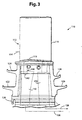
- FIG. 1 illustrates a prior bucket trailing edge cooling circuit, which is part of a closed loop, serpentine circuit extending radially within the bucket. Only part of the bucket cooling circuit is shown.
- the bucket 10 includes an airfoil 12 having a leading edge 14 and a trailing edge 16.
- the airfoil is joined to a horizontal platform 18 along an airfoil fillet 19.
- So called "angel wings" 20, 22 and 24, 26 extend laterally away from the respective front and rear sides of the shank portion 27 of the bucket, and a dovetail portion 28 is employed to mount the bucket on a turbine wheel (not shown) in a conventional manner.
- Trailing edge cooling holes 30, 32 extend internally along and adjacent the trailing edge 16 of the airfoil, while an internal crossover passage 34 extends from the lower end of holes 30, 32 to a coolant supply passage 36 in the dovetail portion of the bucket. Cooling steam (or other medium) will flow via passages 36 and 34 into the trailing edge cooling holes 30, 32. The cooling steam reverses direction (indicated by a flow arrow at the tip of the airfoil) and travels radially inwardly via a passage (not shown) flowing eventually into the cooling steam return passage 38.
- the bucket 110 includes an airfoil 112 having a leading edge 114 and a trailing edge 116.
- the airfoil joins the platform 118 along an airfoil fillet 119.
- the bucket 110 also has angel wings 120, 122 and 124, 126 as well as dovetail portion 128.
- Radially extending trailing edge cooling passages, in the form of drilled holes 130, 132 extend internally along and adjacent the trailing edge 116. In this construction, however, the cooling supply passage 136 (see Fig.
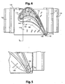
- a new crossover inlet 142 extends horizontally between the chamber 140 and a new crossover cooling passage 144 which has a radial (or vertical, as viewed in Figures 3 and 6 ) leg 146 and a horizontal leg 148 which extends along the underside of the platform 118 from the forward or leading side of the bucket to the rearward or trailing side of the bucket (as best seen in Figures 5 ) where the passage intersects the trailing edge cooling holes 130, 132.
- the cooling steam flows radially outwardly along the trailing edge and then reverses direction, flowing radially inwardly, dumping into chamber 150 which, in turn, connects to the cooling return passage 138.
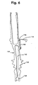
- FIG 4 some of the radial passages for the internal bucket cooling circuit are shown in Figure 4 , one such passage indicated at 152.
- Figure 5 it can be seen how the new core will provide a better target for the drilled trailing edge cooling holes 130, 132.
- Figure 6 also illustrates the manner in which the airfoil is drilled through the main body so as to connect the passage 146 with the inlet 142 leading to the interior chamber 140. The hole is then plugged at 154.
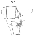
- FIG. 7 illustrates an alternative arrangement where a plug 156 is inserted into the drilled hole providing the communication between chamber 140 and passage 146 via inlet 142.
- the plug 156 is formed with metering holes 158 and 160 which meter air from the chamber 140 into the passage 146.
- This arrangement is particularly suitable where there are no trailing edge holes to meter the flow as, for example, in second stage buckets where the cooling flow is toward the leading edge of the bucket, and then in a radially extending passage in the airfoil portion of the bucket.
- the manner in which the crossover passage is formed and the manner in which access is provided to form interior passages for metering is dependent upon the manufacturing process used to produce the bucket. Where no separate metering mechanism is provided, the trailing edge holes 130, 132 are sized to meter the cooling air.
Landscapes
- Engineering & Computer Science (AREA)
- Mechanical Engineering (AREA)
- General Engineering & Computer Science (AREA)
- Chemical & Material Sciences (AREA)
- Combustion & Propulsion (AREA)
- Turbine Rotor Nozzle Sealing (AREA)
Applications Claiming Priority (2)
| Application Number | Priority Date | Filing Date | Title |
|---|---|---|---|
| US09/496,715 US6390774B1 (en) | 2000-02-02 | 2000-02-02 | Gas turbine bucket cooling circuit and related process |
| US496715 | 2000-02-02 |
Publications (3)
| Publication Number | Publication Date |
|---|---|
| EP1122405A2 EP1122405A2 (en) | 2001-08-08 |
| EP1122405A3 EP1122405A3 (en) | 2004-01-07 |
| EP1122405B1 true EP1122405B1 (en) | 2010-12-08 |
Family
ID=23973815
Family Applications (1)
| Application Number | Title | Priority Date | Filing Date |
|---|---|---|---|
| EP00308612A Expired - Lifetime EP1122405B1 (en) | 2000-02-02 | 2000-09-29 | Gas turbine bucket cooling circuit |
Country Status (7)
| Country | Link |
|---|---|
| US (1) | US6390774B1 (enExample) |
| EP (1) | EP1122405B1 (enExample) |
| JP (1) | JP4731001B2 (enExample) |
| KR (1) | KR20010077887A (enExample) |
| AT (1) | ATE491080T1 (enExample) |
| CZ (1) | CZ20003307A3 (enExample) |
| DE (1) | DE60045333D1 (enExample) |
Cited By (2)
| Publication number | Priority date | Publication date | Assignee | Title |
|---|---|---|---|---|
| US9638051B2 (en) | 2013-09-04 | 2017-05-02 | General Electric Company | Turbomachine bucket having angel wing for differently sized discouragers and related methods |
| US9810072B2 (en) | 2014-05-28 | 2017-11-07 | General Electric Company | Rotor blade cooling |
Families Citing this family (42)
| Publication number | Priority date | Publication date | Assignee | Title |
|---|---|---|---|---|
| US6932570B2 (en) * | 2002-05-23 | 2005-08-23 | General Electric Company | Methods and apparatus for extending gas turbine engine airfoils useful life |
| US6832893B2 (en) * | 2002-10-24 | 2004-12-21 | Pratt & Whitney Canada Corp. | Blade passive cooling feature |
| US20040169013A1 (en) * | 2003-02-28 | 2004-09-02 | General Electric Company | Method for chemically removing aluminum-containing materials from a substrate |
| US6773229B1 (en) | 2003-03-14 | 2004-08-10 | General Electric Company | Turbine nozzle having angel wing seal lands and associated welding method |
| US20050000674A1 (en) * | 2003-07-01 | 2005-01-06 | Beddard Thomas Bradley | Perimeter-cooled stage 1 bucket core stabilizing device and related method |
| US6966756B2 (en) * | 2004-01-09 | 2005-11-22 | General Electric Company | Turbine bucket cooling passages and internal core for producing the passages |
| US7097424B2 (en) | 2004-02-03 | 2006-08-29 | United Technologies Corporation | Micro-circuit platform |
| US7097417B2 (en) * | 2004-02-09 | 2006-08-29 | Siemens Westinghouse Power Corporation | Cooling system for an airfoil vane |
| US7207775B2 (en) * | 2004-06-03 | 2007-04-24 | General Electric Company | Turbine bucket with optimized cooling circuit |
| US7147439B2 (en) * | 2004-09-15 | 2006-12-12 | General Electric Company | Apparatus and methods for cooling turbine bucket platforms |
| FR2877034B1 (fr) | 2004-10-27 | 2009-04-03 | Snecma Moteurs Sa | Aube de rotor d'une turbine a gaz |
| US7198458B2 (en) | 2004-12-02 | 2007-04-03 | Siemens Power Generation, Inc. | Fail safe cooling system for turbine vanes |
| US7153096B2 (en) * | 2004-12-02 | 2006-12-26 | Siemens Power Generation, Inc. | Stacked laminate CMC turbine vane |
| US7255535B2 (en) * | 2004-12-02 | 2007-08-14 | Albrecht Harry A | Cooling systems for stacked laminate CMC vane |
| US7255536B2 (en) | 2005-05-23 | 2007-08-14 | United Technologies Corporation | Turbine airfoil platform cooling circuit |
| US7465152B2 (en) * | 2005-09-16 | 2008-12-16 | General Electric Company | Angel wing seals for turbine blades and methods for selecting stator, rotor and wing seal profiles |
| US7309212B2 (en) | 2005-11-21 | 2007-12-18 | General Electric Company | Gas turbine bucket with cooled platform leading edge and method of cooling platform leading edge |
| US7695246B2 (en) * | 2006-01-31 | 2010-04-13 | United Technologies Corporation | Microcircuits for small engines |
| US7416391B2 (en) * | 2006-02-24 | 2008-08-26 | General Electric Company | Bucket platform cooling circuit and method |
| US7766606B2 (en) * | 2006-08-17 | 2010-08-03 | Siemens Energy, Inc. | Turbine airfoil cooling system with platform cooling channels with diffusion slots |
| US20100034662A1 (en) * | 2006-12-26 | 2010-02-11 | General Electric Company | Cooled airfoil and method for making an airfoil having reduced trail edge slot flow |
| US8052395B2 (en) * | 2007-09-28 | 2011-11-08 | General Electric Company | Air cooled bucket for a turbine |
| US8147188B2 (en) * | 2007-09-28 | 2012-04-03 | General Electric Company | Air cooled bucket for a turbine |
| US8511990B2 (en) * | 2009-06-24 | 2013-08-20 | General Electric Company | Cooling hole exits for a turbine bucket tip shroud |
| US8523527B2 (en) * | 2010-03-10 | 2013-09-03 | General Electric Company | Apparatus for cooling a platform of a turbine component |
| US8647064B2 (en) * | 2010-08-09 | 2014-02-11 | General Electric Company | Bucket assembly cooling apparatus and method for forming the bucket assembly |
| US9416666B2 (en) | 2010-09-09 | 2016-08-16 | General Electric Company | Turbine blade platform cooling systems |
| US8814518B2 (en) * | 2010-10-29 | 2014-08-26 | General Electric Company | Apparatus and methods for cooling platform regions of turbine rotor blades |
| US8636471B2 (en) | 2010-12-20 | 2014-01-28 | General Electric Company | Apparatus and methods for cooling platform regions of turbine rotor blades |
| US8628300B2 (en) * | 2010-12-30 | 2014-01-14 | General Electric Company | Apparatus and methods for cooling platform regions of turbine rotor blades |
| US8753083B2 (en) | 2011-01-14 | 2014-06-17 | General Electric Company | Curved cooling passages for a turbine component |
| US9447691B2 (en) * | 2011-08-22 | 2016-09-20 | General Electric Company | Bucket assembly treating apparatus and method for treating bucket assembly |
| US8858160B2 (en) * | 2011-11-04 | 2014-10-14 | General Electric Company | Bucket assembly for turbine system |
| US9022735B2 (en) * | 2011-11-08 | 2015-05-05 | General Electric Company | Turbomachine component and method of connecting cooling circuits of a turbomachine component |
| US9127561B2 (en) | 2012-03-01 | 2015-09-08 | General Electric Company | Turbine bucket with contoured internal rib |
| US9109454B2 (en) * | 2012-03-01 | 2015-08-18 | General Electric Company | Turbine bucket with pressure side cooling |
| US8974182B2 (en) | 2012-03-01 | 2015-03-10 | General Electric Company | Turbine bucket with a core cavity having a contoured turn |
| US10697306B2 (en) | 2014-09-18 | 2020-06-30 | Siemens Aktiengesellschaft | Gas turbine airfoil including integrated leading edge and tip cooling fluid passage and core structure used for forming such an airfoil |
| US20190085706A1 (en) * | 2017-09-18 | 2019-03-21 | General Electric Company | Turbine engine airfoil assembly |
| US10731475B2 (en) | 2018-04-20 | 2020-08-04 | Raytheon Technologies Corporation | Blade with inlet orifice on aft face of root |
| JP7129277B2 (ja) * | 2018-08-24 | 2022-09-01 | 三菱重工業株式会社 | 翼およびガスタービン |
| US12286900B2 (en) | 2021-12-28 | 2025-04-29 | Mitsubishi Heavy Industries, Ltd. | Rotor blade and gas turbine provided therewith |
Family Cites Families (22)
| Publication number | Priority date | Publication date | Assignee | Title |
|---|---|---|---|---|
| GB754217A (en) | 1953-01-30 | 1956-08-08 | Gen Motors Corp | Improvements relating to turbine blades |
| US3844679A (en) | 1973-03-28 | 1974-10-29 | Gen Electric | Pressurized serpentine cooling channel construction for open-circuit liquid cooled turbine buckets |
| US4212587A (en) * | 1978-05-30 | 1980-07-15 | General Electric Company | Cooling system for a gas turbine using V-shaped notch weirs |
| US4242045A (en) * | 1979-06-01 | 1980-12-30 | General Electric Company | Trap seal for open circuit liquid cooled turbines |
| US4244676A (en) * | 1979-06-01 | 1981-01-13 | General Electric Company | Cooling system for a gas turbine using a cylindrical insert having V-shaped notch weirs |
| GB2082257B (en) | 1980-08-08 | 1984-02-15 | Gen Electric | Liquid coolant distribution systems for gas turbines |
| US4775296A (en) * | 1981-12-28 | 1988-10-04 | United Technologies Corporation | Coolable airfoil for a rotary machine |
| JPS61205301A (ja) * | 1985-03-06 | 1986-09-11 | Hitachi Ltd | ガスタ−ビン翼 |
| US5340278A (en) * | 1992-11-24 | 1994-08-23 | United Technologies Corporation | Rotor blade with integral platform and a fillet cooling passage |
| JPH07119405A (ja) * | 1993-10-26 | 1995-05-09 | Hitachi Ltd | ガスタービン冷却翼 |
| US5491971A (en) | 1993-12-23 | 1996-02-20 | General Electric Co. | Closed circuit air cooled gas turbine combined cycle |
| US5591002A (en) | 1994-08-23 | 1997-01-07 | General Electric Co. | Closed or open air cooling circuits for nozzle segments with wheelspace purge |
| US5536143A (en) | 1995-03-31 | 1996-07-16 | General Electric Co. | Closed circuit steam cooled bucket |
| JP2851578B2 (ja) * | 1996-03-12 | 1999-01-27 | 三菱重工業株式会社 | ガスタービン翼 |
| JP3426841B2 (ja) | 1996-04-15 | 2003-07-14 | 三菱重工業株式会社 | ガスタービン動翼 |
| US5823741A (en) | 1996-09-25 | 1998-10-20 | General Electric Co. | Cooling joint connection for abutting segments in a gas turbine engine |
| DE19713268B4 (de) | 1997-03-29 | 2006-01-19 | Alstom | Gekühlte Gasturbinenschaufel |
| US5915923A (en) * | 1997-05-22 | 1999-06-29 | Mitsubishi Heavy Industries, Ltd. | Gas turbine moving blade |
| US6190130B1 (en) | 1998-03-03 | 2001-02-20 | Mitsubishi Heavy Industries, Ltd. | Gas turbine moving blade platform |
| US6092991A (en) * | 1998-03-05 | 2000-07-25 | Mitsubishi Heavy Industries, Ltd. | Gas turbine blade |
| US6065931A (en) * | 1998-03-05 | 2000-05-23 | Mitsubishi Heavy Industries, Ltd. | Gas turbine moving blade |
| CA2231988C (en) | 1998-03-12 | 2002-05-28 | Mitsubishi Heavy Industries, Ltd. | Gas turbine blade |
-
2000
- 2000-02-02 US US09/496,715 patent/US6390774B1/en not_active Expired - Lifetime
- 2000-09-11 CZ CZ20003307A patent/CZ20003307A3/cs unknown
- 2000-09-29 EP EP00308612A patent/EP1122405B1/en not_active Expired - Lifetime
- 2000-09-29 KR KR1020000057411A patent/KR20010077887A/ko not_active Ceased
- 2000-09-29 JP JP2000297789A patent/JP4731001B2/ja not_active Expired - Lifetime
- 2000-09-29 AT AT00308612T patent/ATE491080T1/de not_active IP Right Cessation
- 2000-09-29 DE DE60045333T patent/DE60045333D1/de not_active Expired - Lifetime
Cited By (2)
| Publication number | Priority date | Publication date | Assignee | Title |
|---|---|---|---|---|
| US9638051B2 (en) | 2013-09-04 | 2017-05-02 | General Electric Company | Turbomachine bucket having angel wing for differently sized discouragers and related methods |
| US9810072B2 (en) | 2014-05-28 | 2017-11-07 | General Electric Company | Rotor blade cooling |
Also Published As
| Publication number | Publication date |
|---|---|
| CZ20003307A3 (cs) | 2001-09-12 |
| JP4731001B2 (ja) | 2011-07-20 |
| KR20010077887A (ko) | 2001-08-20 |
| JP2001214703A (ja) | 2001-08-10 |
| EP1122405A3 (en) | 2004-01-07 |
| ATE491080T1 (de) | 2010-12-15 |
| US6390774B1 (en) | 2002-05-21 |
| DE60045333D1 (de) | 2011-01-20 |
| EP1122405A2 (en) | 2001-08-08 |
Similar Documents
| Publication | Publication Date | Title |
|---|---|---|
| EP1122405B1 (en) | Gas turbine bucket cooling circuit | |
| EP1936118B1 (en) | Turbine blade main core modifications for peripheral serpentine microcircuits | |
| EP1267037B1 (en) | Cooled hollow tip shroud of a turbine blade | |
| EP1900904B1 (en) | Multi-peripheral serpentine microcircuits for high aspect ratio blades | |
| US5348446A (en) | Bimetallic turbine airfoil | |
| US7033136B2 (en) | Cooling circuits for a gas turbine blade | |
| EP2246133B1 (en) | RMC-defined tip blowing slots for turbine blades | |
| EP1087102B1 (en) | Gas turbine bucket with impingement cooled platform | |
| US7963745B1 (en) | Composite turbine blade | |
| US6991430B2 (en) | Turbine blade with recessed squealer tip and shelf | |
| US5387086A (en) | Gas turbine blade with improved cooling | |
| EP1882816B1 (en) | Radially split serpentine cooling microcircuits | |
| US7744347B2 (en) | Peripheral microcircuit serpentine cooling for turbine airfoils | |
| US5246340A (en) | Internally cooled airfoil | |
| US5813836A (en) | Turbine blade | |
| US7255536B2 (en) | Turbine airfoil platform cooling circuit | |
| EP1878874B1 (en) | Integral main body-tip microcircuit for blades | |
| US7597536B1 (en) | Turbine airfoil with de-coupled platform | |
| JP2001003704A (ja) | 内部冷却式タービン翼形部 | |
| US8186953B1 (en) | Multiple piece turbine blade | |
| EP1884621A2 (en) | Serpentine microciruit cooling with pressure side features | |
| US20200378277A1 (en) | Turbine blade with dust tolerant cooling system | |
| EP2597262B1 (en) | Bucket assembly for turbine system | |
| EP1881157B1 (en) | Serpentine microcircuits for local heat removal |
Legal Events
| Date | Code | Title | Description |
|---|---|---|---|
| PUAI | Public reference made under article 153(3) epc to a published international application that has entered the european phase |
Free format text: ORIGINAL CODE: 0009012 |
|
| AK | Designated contracting states |
Kind code of ref document: A2 Designated state(s): AT BE CH CY DE DK ES FI FR GB GR IE IT LI LU MC NL PT SE |
|
| AX | Request for extension of the european patent |
Free format text: AL;LT;LV;MK;RO;SI |
|
| PUAL | Search report despatched |
Free format text: ORIGINAL CODE: 0009013 |
|
| AK | Designated contracting states |
Kind code of ref document: A3 Designated state(s): AT BE CH CY DE DK ES FI FR GB GR IE IT LI LU MC NL PT SE |
|
| AX | Request for extension of the european patent |
Extension state: AL LT LV MK RO SI |
|
| 17P | Request for examination filed |
Effective date: 20040707 |
|
| AKX | Designation fees paid |
Designated state(s): AT BE CH CY DE DK ES FI FR GB GR IE IT LI LU MC NL PT SE |
|
| GRAP | Despatch of communication of intention to grant a patent |
Free format text: ORIGINAL CODE: EPIDOSNIGR1 |
|
| GRAS | Grant fee paid |
Free format text: ORIGINAL CODE: EPIDOSNIGR3 |
|
| GRAA | (expected) grant |
Free format text: ORIGINAL CODE: 0009210 |
|
| AK | Designated contracting states |
Kind code of ref document: B1 Designated state(s): AT BE CH CY DE DK ES FI FR GB GR IE IT LI LU MC NL PT SE |
|
| REG | Reference to a national code |
Ref country code: GB Ref legal event code: FG4D |
|
| REG | Reference to a national code |
Ref country code: CH Ref legal event code: EP |
|
| REG | Reference to a national code |
Ref country code: IE Ref legal event code: FG4D |
|
| REG | Reference to a national code |
Ref country code: CH Ref legal event code: NV Representative=s name: SERVOPATENT GMBH |
|
| REF | Corresponds to: |
Ref document number: 60045333 Country of ref document: DE Date of ref document: 20110120 Kind code of ref document: P |
|
| REG | Reference to a national code |
Ref country code: NL Ref legal event code: VDEP Effective date: 20101208 |
|
| PG25 | Lapsed in a contracting state [announced via postgrant information from national office to epo] |
Ref country code: SE Free format text: LAPSE BECAUSE OF FAILURE TO SUBMIT A TRANSLATION OF THE DESCRIPTION OR TO PAY THE FEE WITHIN THE PRESCRIBED TIME-LIMIT Effective date: 20101208 Ref country code: CY Free format text: LAPSE BECAUSE OF FAILURE TO SUBMIT A TRANSLATION OF THE DESCRIPTION OR TO PAY THE FEE WITHIN THE PRESCRIBED TIME-LIMIT Effective date: 20101208 Ref country code: FI Free format text: LAPSE BECAUSE OF FAILURE TO SUBMIT A TRANSLATION OF THE DESCRIPTION OR TO PAY THE FEE WITHIN THE PRESCRIBED TIME-LIMIT Effective date: 20101208 Ref country code: AT Free format text: LAPSE BECAUSE OF FAILURE TO SUBMIT A TRANSLATION OF THE DESCRIPTION OR TO PAY THE FEE WITHIN THE PRESCRIBED TIME-LIMIT Effective date: 20101208 Ref country code: NL Free format text: LAPSE BECAUSE OF FAILURE TO SUBMIT A TRANSLATION OF THE DESCRIPTION OR TO PAY THE FEE WITHIN THE PRESCRIBED TIME-LIMIT Effective date: 20101208 |
|
| PG25 | Lapsed in a contracting state [announced via postgrant information from national office to epo] |
Ref country code: BE Free format text: LAPSE BECAUSE OF FAILURE TO SUBMIT A TRANSLATION OF THE DESCRIPTION OR TO PAY THE FEE WITHIN THE PRESCRIBED TIME-LIMIT Effective date: 20101208 Ref country code: PT Free format text: LAPSE BECAUSE OF FAILURE TO SUBMIT A TRANSLATION OF THE DESCRIPTION OR TO PAY THE FEE WITHIN THE PRESCRIBED TIME-LIMIT Effective date: 20110408 Ref country code: GR Free format text: LAPSE BECAUSE OF FAILURE TO SUBMIT A TRANSLATION OF THE DESCRIPTION OR TO PAY THE FEE WITHIN THE PRESCRIBED TIME-LIMIT Effective date: 20110309 Ref country code: ES Free format text: LAPSE BECAUSE OF FAILURE TO SUBMIT A TRANSLATION OF THE DESCRIPTION OR TO PAY THE FEE WITHIN THE PRESCRIBED TIME-LIMIT Effective date: 20110319 |
|
| PLBE | No opposition filed within time limit |
Free format text: ORIGINAL CODE: 0009261 |
|
| STAA | Information on the status of an ep patent application or granted ep patent |
Free format text: STATUS: NO OPPOSITION FILED WITHIN TIME LIMIT |
|
| PG25 | Lapsed in a contracting state [announced via postgrant information from national office to epo] |
Ref country code: DK Free format text: LAPSE BECAUSE OF FAILURE TO SUBMIT A TRANSLATION OF THE DESCRIPTION OR TO PAY THE FEE WITHIN THE PRESCRIBED TIME-LIMIT Effective date: 20101208 |
|
| 26N | No opposition filed |
Effective date: 20110909 |
|
| PG25 | Lapsed in a contracting state [announced via postgrant information from national office to epo] |
Ref country code: IT Free format text: LAPSE BECAUSE OF FAILURE TO SUBMIT A TRANSLATION OF THE DESCRIPTION OR TO PAY THE FEE WITHIN THE PRESCRIBED TIME-LIMIT Effective date: 20101208 |
|
| REG | Reference to a national code |
Ref country code: DE Ref legal event code: R097 Ref document number: 60045333 Country of ref document: DE Effective date: 20110909 |
|
| PG25 | Lapsed in a contracting state [announced via postgrant information from national office to epo] |
Ref country code: MC Free format text: LAPSE BECAUSE OF NON-PAYMENT OF DUE FEES Effective date: 20110930 |
|
| REG | Reference to a national code |
Ref country code: IE Ref legal event code: MM4A |
|
| PG25 | Lapsed in a contracting state [announced via postgrant information from national office to epo] |
Ref country code: IE Free format text: LAPSE BECAUSE OF NON-PAYMENT OF DUE FEES Effective date: 20110929 |
|
| PG25 | Lapsed in a contracting state [announced via postgrant information from national office to epo] |
Ref country code: LU Free format text: LAPSE BECAUSE OF NON-PAYMENT OF DUE FEES Effective date: 20110929 |
|
| REG | Reference to a national code |
Ref country code: FR Ref legal event code: PLFP Year of fee payment: 17 |
|
| REG | Reference to a national code |
Ref country code: FR Ref legal event code: PLFP Year of fee payment: 18 |
|
| REG | Reference to a national code |
Ref country code: FR Ref legal event code: PLFP Year of fee payment: 19 |
|
| PGFP | Annual fee paid to national office [announced via postgrant information from national office to epo] |
Ref country code: FR Payment date: 20190820 Year of fee payment: 20 Ref country code: DE Payment date: 20190820 Year of fee payment: 20 |
|
| PGFP | Annual fee paid to national office [announced via postgrant information from national office to epo] |
Ref country code: GB Payment date: 20190820 Year of fee payment: 20 |
|
| PGFP | Annual fee paid to national office [announced via postgrant information from national office to epo] |
Ref country code: CH Payment date: 20190820 Year of fee payment: 20 |
|
| REG | Reference to a national code |
Ref country code: CH Ref legal event code: PCAR Free format text: NEW ADDRESS: WANNERSTRASSE 9/1, 8045 ZUERICH (CH) |
|
| REG | Reference to a national code |
Ref country code: DE Ref legal event code: R071 Ref document number: 60045333 Country of ref document: DE |
|
| REG | Reference to a national code |
Ref country code: CH Ref legal event code: PL |
|
| REG | Reference to a national code |
Ref country code: GB Ref legal event code: PE20 Expiry date: 20200928 |
|
| PG25 | Lapsed in a contracting state [announced via postgrant information from national office to epo] |
Ref country code: GB Free format text: LAPSE BECAUSE OF EXPIRATION OF PROTECTION Effective date: 20200928 |