EP1121990A2 - Device for rolling strips with a periodically variable thickness - Google Patents
Device for rolling strips with a periodically variable thickness Download PDFInfo
- Publication number
- EP1121990A2 EP1121990A2 EP01102289A EP01102289A EP1121990A2 EP 1121990 A2 EP1121990 A2 EP 1121990A2 EP 01102289 A EP01102289 A EP 01102289A EP 01102289 A EP01102289 A EP 01102289A EP 1121990 A2 EP1121990 A2 EP 1121990A2
- Authority
- EP
- European Patent Office
- Prior art keywords
- strip
- roll
- thickness
- reel
- roll gap
- Prior art date
- Legal status (The legal status is an assumption and is not a legal conclusion. Google has not performed a legal analysis and makes no representation as to the accuracy of the status listed.)
- Granted
Links
- 238000005096 rolling process Methods 0.000 title claims description 21
- 230000001105 regulatory effect Effects 0.000 claims abstract 2
- 239000000463 material Substances 0.000 claims description 14
- 230000008859 change Effects 0.000 claims description 8
- 230000000737 periodic effect Effects 0.000 claims description 4
- 230000001133 acceleration Effects 0.000 claims description 3
- 238000012937 correction Methods 0.000 claims description 2
- 238000004804 winding Methods 0.000 claims description 2
- 125000004122 cyclic group Chemical group 0.000 claims 1
- 238000013000 roll bending Methods 0.000 claims 1
- 239000002184 metal Substances 0.000 description 6
- 238000000034 method Methods 0.000 description 5
- 230000008569 process Effects 0.000 description 4
- 238000010586 diagram Methods 0.000 description 3
- 238000004519 manufacturing process Methods 0.000 description 3
- 230000008030 elimination Effects 0.000 description 2
- 238000003379 elimination reaction Methods 0.000 description 2
- 238000005259 measurement Methods 0.000 description 2
- 230000002093 peripheral effect Effects 0.000 description 2
- 230000001629 suppression Effects 0.000 description 2
- 230000033228 biological regulation Effects 0.000 description 1
- 230000001364 causal effect Effects 0.000 description 1
- 238000005097 cold rolling Methods 0.000 description 1
- 238000010276 construction Methods 0.000 description 1
- 238000011217 control strategy Methods 0.000 description 1
- 230000003111 delayed effect Effects 0.000 description 1
- 230000006872 improvement Effects 0.000 description 1
- 230000001788 irregular Effects 0.000 description 1
- 230000009467 reduction Effects 0.000 description 1
- 230000007704 transition Effects 0.000 description 1
Images

Classifications
-
- B—PERFORMING OPERATIONS; TRANSPORTING
- B21—MECHANICAL METAL-WORKING WITHOUT ESSENTIALLY REMOVING MATERIAL; PUNCHING METAL
- B21B—ROLLING OF METAL
- B21B37/00—Control devices or methods specially adapted for metal-rolling mills or the work produced thereby
- B21B37/16—Control of thickness, width, diameter or other transverse dimensions
- B21B37/24—Automatic variation of thickness according to a predetermined programme
- B21B37/26—Automatic variation of thickness according to a predetermined programme for obtaining one strip having successive lengths of different constant thickness
-
- B—PERFORMING OPERATIONS; TRANSPORTING
- B21—MECHANICAL METAL-WORKING WITHOUT ESSENTIALLY REMOVING MATERIAL; PUNCHING METAL
- B21B—ROLLING OF METAL
- B21B37/00—Control devices or methods specially adapted for metal-rolling mills or the work produced thereby
- B21B37/48—Tension control; Compression control
-
- B—PERFORMING OPERATIONS; TRANSPORTING
- B21—MECHANICAL METAL-WORKING WITHOUT ESSENTIALLY REMOVING MATERIAL; PUNCHING METAL
- B21B—ROLLING OF METAL
- B21B37/00—Control devices or methods specially adapted for metal-rolling mills or the work produced thereby
- B21B37/28—Control of flatness or profile during rolling of strip, sheets or plates
- B21B37/38—Control of flatness or profile during rolling of strip, sheets or plates using roll bending
-
- B—PERFORMING OPERATIONS; TRANSPORTING
- B21—MECHANICAL METAL-WORKING WITHOUT ESSENTIALLY REMOVING MATERIAL; PUNCHING METAL
- B21B—ROLLING OF METAL
- B21B37/00—Control devices or methods specially adapted for metal-rolling mills or the work produced thereby
- B21B37/48—Tension control; Compression control
- B21B37/52—Tension control; Compression control by drive motor control
- B21B37/54—Tension control; Compression control by drive motor control including coiler drive control, e.g. reversing mills
-
- B—PERFORMING OPERATIONS; TRANSPORTING
- B21—MECHANICAL METAL-WORKING WITHOUT ESSENTIALLY REMOVING MATERIAL; PUNCHING METAL
- B21B—ROLLING OF METAL
- B21B39/00—Arrangements for moving, supporting, or positioning work, or controlling its movement, combined with or arranged in, or specially adapted for use in connection with, metal-rolling mills
- B21B39/02—Feeding or supporting work; Braking or tensioning arrangements, e.g. threading arrangements
- B21B39/08—Braking or tensioning arrangements
Definitions
- the present invention relates to the rolling of strips, by means of a roll stand with a set of rollers for limitation of the roll gap and an adjustment system for determination the width of the roll gap.
- a decoiler Located in front of the rolling stand there is a decoiler, a decoiler is the roll stand subordinate.
- the strip material to be reduced in thickness is unwound from the decoiler under tension, passed through the nip between the rolls of the roll set and again under tension on the take-up reel wound up.
- the aim is to be as uniform as possible Thickness of the strip-like rolling stock after leaving the Roll gap, as is naturally the case on the decoiler strip-shaped starting rolling stock in the form of a coil the same possible thickness over the entire length Length.
- strip-shaped rolling stock has a starting thickness that is as constant as possible and have a constant, smaller final thickness as possible. Should, for example in body construction, sheet metal in various Areas have different thicknesses, so are metal strips different thicknesses welded together.
- Sheet metal strips have already been rolled in the laboratory Longitudinal direction of the belt successive belt sections of different thicknesses. One-off sections follow different sections Thicknesses on each other, it can be relatively easy by changing the width of the roll gap.
- stripe sections should be different Thicknesses follow one another, so only a relatively small one Belt speed a smooth transition between the individual band sections of different thicknesses guaranteed become.
- the possible tape running speed is too low to the laboratory operation in the area of industrial mass production to take over.
- the problems with the production of tapes periodically consecutive band sections different Strip thicknesses are due to the fact that when changing the degree of rolling, the belt speeds on Change the entrance and exit of the roll gap and advance and backing up the tape relative to the peripheral speed of the Change work rolls with the stitch change. That’s why the speed of the reel drives is constantly changing Process conditions are adjusted. For this are speed changes up to 50% of the nominal speed in short time (e.g. 0.15 seconds) is required. This leads to the previously known cold rolling mills for violent fluctuations in strip tension. This results in an irregular structure of what is to be wound up Coils, impermissible deviations in the final roll thickness of their setpoint, risk of belt breaks and damage to system parts.
- a rolling mill becomes more relevant State of the art provided that there is a decoiler on the inlet side in front of a roll stand and preferably also pulleys, Has tape tension measuring devices and tape thickness measuring devices as well a reel on the outlet side according to the roll stand mentioned and preferably again deflection rollers, tape tension measuring devices and has tape thickness gauges. It is marked Invention above all through a balancing or dancer role on the inlet side and another dancer roll on the outlet side.
- the roll stand (main drive) is speed-controlled on the desired speed set. In stationary Rolling operation, the rollers rotate with practically constant Peripheral speed.
- the dancer roles are force-controlled with the task, the desired one Apply tape tension.
- the reel is speed controlled, with the target speed taking into account the respective coil diameter the average of the belt speed is set.
- the positions of the dancer rolls are monitored and control signals for correcting the reel speeds are derived, for example as follows: If the dancer roll on the inlet side drops too low below the lower switching point, the uncoiling is delayed accordingly. If this dancer roll rises too far above the upper switching point, the uncoiling is accelerated. If the dancer roll on the outlet side sinks too far, the reel must travel a little faster and vice versa.
- the belt pulls on the inlet and outlet sides of the roll stand are practically constant (within narrow tolerances).
- the tape thickness can be varied relatively arbitrarily, without risking tape breaks and damage to the system.
- FIG. 2 A rolling mill with a compensating roller according to the invention or dancer roll on the inlet and outlet side of a Roll stand is shown in Fig. 2 and described below. It is understood that this is only a Embodiment of the invention is.
- a roll stand 1 is arranged in the center of the rolling mill, in the two work rolls 2, 3 determine the width of the roll gap, through which the band-shaped rolling material 4 is forcibly passed is to the actual thickness of the rolling material 4 before Roll stand 1 to the smaller target thickness after the roll stand 1 to reduce. Otherwise, the structure of the roll stand corresponds 1 the state of the art, so that further representation and Description is dispensed with and only two backup rollers or rollers 5, 6 and a device 7 are shown, with the device 7, the rollers perpendicular to the metal strip are adjustable to determine the width of the roll gap or to be able to change.
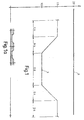
- the input thickness of the tape 4 before the roll stand 1 is assumed to be constant, as is the section 8 shows the line in the diagram according to FIG.
- the thickness of the strip material should be reduced to a target value as determined by the Section 9 of the line in the diagram shown in FIG. 1 is.
- This target thickness of the strip material should now differ not constant from the state of the art, but rather be different, the change in target thickness periodically should repeat itself at a relatively high level Belt running speed (partial figure 1a).
- the roll stand 1 is speed-controlled and set to the desired target speed
- the dancer rolls 12, 13 are force-controlled to achieve the desired To apply the tape tension
- the reels 10 and 11 are speed-controlled, taking into account the target speed of the respective coil diameter to the mean value of the belt speed is set, i.e. that from the uncoiler 10 as much tape 4 is unwound as the rolling stand 1 moves in and that so much tape 4 is wound up from the reel 11, as the mill stand 1 releases on the outlet side.
- the dancer roles 12, 13 are adjustable up and down like it is expressed by the double arrows 14, 15. To the functions reference is made in detail to what has been said above.
- the rolling force corresponding to the periodic or cyclical variable changes in thickness of the strip material periodically or fluctuates cyclically.
- This can lead to in the strip material in its central region in the longitudinal direction of the strip form successive waves when the thickness decrease of the rolled strip is relatively small, and that form such waves in the edge areas of the rolled strip, if the reduction in thickness of the rolled strip is relatively large.
- the Problem of this edge or medium wave training is manageable, if periodic changes in thickness in relative large intervals are made and the adjustments to the need the edge wave suppression or elimination and Medium wave suppression or elimination only at large intervals exists, be it because of the spatial, or because of the time intervals between two successive changes in thickness are correspondingly large, or, in other words, Flatness control systems only on relatively long-wave Process changes have to react.
- the present invention shows in her further training how the described Problem can be solved if the distance between two each of periodically recurring changes in thickness short and in particular shorter than the distance between the Roll stand and a flatness measuring system is.
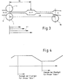
- the problem is illustrated in FIG. 3.
- the mill stand 1 follows a thickness measurement on the rolled strip 4 in the thick area n + 1, in Distance 18 from the mill stand, while in the direction of Roll strip feed preceding thick strip area n at a distance 19 from the roll stand 12 by means of a flatness measuring system 16 the flatness of the rolled strip is determined.
- the next thick area has n + 1 already leave the mill stand 1, a consideration is no longer possible for the range n + 1, but only for later thick strip sections from n + 2, for the a new appointment has been made. This condition should be removed and corrections to maintain optimal flatness can be taken into account for the rolling of the section n + 1.
- Determining the deviation of the actual value from the target value and a new setpoint is already calculated for the next strip section to be rolled.
Abstract
Description
Die vorliegende Erfindung bezieht sich auf das Walzen von Bändern, mittels eines Walzgerüstes mit einem Walzensatz zur Begrenzung des Walzspaltes und einem Anstellsystem zur Bestimmung der Weite des Walzspaltes. Vor dem Walzgerüst befindet sich eine Abwickelhaspel, eine Aufwickelhaspel ist dem Walzgerüst nachgeordnet. Das in seiner Dicke zu reduzierende Bandmaterial wird von der Abwickelhaspel unter Zug abgewickelt, durch den Walzspalt zwischen den Walzen des Walzensatzes hindurchgeführt und wiederum unter Zug auf die Aufwickelhaspel aufgewickelt. Angestrebt wird dabei eine möglichst gleichmäßige Dicke des bandförmigen Walzgutes nach dem Verlassen des Walzspaltes, wie selbstverständlich auch das auf der Abwickelhaspel in der Form eines Coils befindliche bandförmige Ausgangswalzgut eine möglichst gleiche Dicke über die gesamte Länge haben soll. Es soll also bei den bekannten Lösungen das bandförmige Walzgut eine möglichst konstante Ausgangsdicke und eine möglichst konstante, geringere Enddicke haben. Sollen, beispielsweise im Karosseriebau, flächige Bleche in verschiedenen Bereichen unterschiedliche Dicken haben, so werden Blechbänder unterschiedlicher Dicken miteinander verschweißt.The present invention relates to the rolling of strips, by means of a roll stand with a set of rollers for limitation of the roll gap and an adjustment system for determination the width of the roll gap. Located in front of the rolling stand there is a decoiler, a decoiler is the roll stand subordinate. The strip material to be reduced in thickness is unwound from the decoiler under tension, passed through the nip between the rolls of the roll set and again under tension on the take-up reel wound up. The aim is to be as uniform as possible Thickness of the strip-like rolling stock after leaving the Roll gap, as is naturally the case on the decoiler strip-shaped starting rolling stock in the form of a coil the same possible thickness over the entire length Length. So it should be with the known solutions strip-shaped rolling stock has a starting thickness that is as constant as possible and have a constant, smaller final thickness as possible. Should, for example in body construction, sheet metal in various Areas have different thicknesses, so are metal strips different thicknesses welded together.
Im Laborbetrieb wurden auch schon Blechbänder gewalzt, die in Längsrichtung des Bandes aufeinanderfolgenden Bandabschnitten unterschiedlicher Dicken haben. Folgen einmalig Abschnitte unterschiedlicher Dicken aufeinander, so kann das relativ problemlos durch Veränderung der Weite des Walzspaltes erfolgen. Sheet metal strips have already been rolled in the laboratory Longitudinal direction of the belt successive belt sections of different thicknesses. One-off sections follow different sections Thicknesses on each other, it can be relatively easy by changing the width of the roll gap.
Sollen jedoch periodisch Streifenabschnitte unterschiedlicher Dicken aufeinanderfolgen, so kann nur bei einer relativ geringen Bandlaufgechwindigkeit ein sauberer Übergang zwischen den einzelnen unterschiedlich dicken Bandabschnitten gewährleistet werden. Die mögliche Bandlaufgeschwindigkeit ist zu gering, um den Laborbetrieb in den Bereich industrieller Massenfertigung zu übernehmen. Die Probleme bei der Fertigung von Bändern mit periodisch aufeinanderfolgenden Bandabschnitten unterschiedlicher Banddicken sind in der Tatsache begründet, dass bei Veränderung des Abwalzgrades sich die Bandgeschwindigkeiten am Eingang und am Ausgang des Walzspaltes verändern und Voreilung und Rückstau des Bandes relativ zur Umfangsgechwindigkeit der Arbeitswalzen mit der Stichveränderung verändern. Darum müssen die Haspelantriebe in ihrer Gechwindigkeit ständig an die veränderlichen Prozeßbedingungen angepaßt werden. Hierzu sind Geschwindigkeitsänderungen bis zu 50% der Nenngeschwindigkeit in kurzer Zeit (z.B. 0,15 Sek.) erforderlich. Dies führt bei den bisher bekannten Kaltwalzwerken zu heftigen Schwankungen der-Bandzüge. Daraus folgen ein unregelmäßiger Aufbau des aufzuwikkelnden Coils, unzulässige Abweichungen der Endwalz-Dicke von ihrem Sollwert, Risiko von Bandrissen und Beschädigung von Anlagenteilen.However, periodically, stripe sections should be different Thicknesses follow one another, so only a relatively small one Belt speed a smooth transition between the individual band sections of different thicknesses guaranteed become. The possible tape running speed is too low to the laboratory operation in the area of industrial mass production to take over. The problems with the production of tapes periodically consecutive band sections different Strip thicknesses are due to the fact that when changing the degree of rolling, the belt speeds on Change the entrance and exit of the roll gap and advance and backing up the tape relative to the peripheral speed of the Change work rolls with the stitch change. That’s why the speed of the reel drives is constantly changing Process conditions are adjusted. For this are speed changes up to 50% of the nominal speed in short time (e.g. 0.15 seconds) is required. This leads to the previously known cold rolling mills for violent fluctuations in strip tension. This results in an irregular structure of what is to be wound up Coils, impermissible deviations in the final roll thickness of their setpoint, risk of belt breaks and damage to system parts.
Mit großen Arbeitsgeschwindigkeiten sind die bisher vorgeschlagenen Verfahren nicht durchführbar. Senkt man die Geschwindigkeit der Anlage so weit ab, dass der Prozeß beherrschbar ist, so wird die Produktionsleistung so gering, dass der anlagetechnische Aufwand nicht gerechtfertigt wird. Mit den bisher gegebenen Möglichkeiten können Bänder mit periodisch aufeinanderfolgenden Bandabschnitten unterschiedlicher Dicke wirtschaftlich nicht gefertigt werden. At high working speeds, the previously proposed are Procedure not feasible. If you lower the speed the system so far that the process is manageable production output is so low that the technical investment is not justified. With the possibilities given so far, tapes can be periodically successive band sections different Thickness cannot be manufactured economically.
Vor diesem technischen und wirtschaftlichen Hintergrund ist es nun Aufgabe der vorliegenden Erfindung, eine Möglichkeit aufzuzeigen, auf wirtschaftlich akzeptable Weise zu Coils aufgewickelte Metall-Bänder unter Zug abzuwickeln, in der Dicke zu reduzieren und anschließend unter Zug wieder aufzuwickeln, wobei eine relativ konstante Banddicke (= Ist-Dicke) auf der Einlaufseite unterstellt werden soll und eine periodisch veränderliche Banddicke (=Soll-Dicke) auf der Auslaufseite erreichbar sein woll, wie es in Fig. 1 diagrammartig dargestellt ist.Against this technical and economic background, it is now the object of the present invention to show a possibility wound into coils in an economically acceptable manner Unwind metal strips under tension, in thickness too reduce and then rewind under tension, whereby a relatively constant strip thickness (= actual thickness) on the Inlet side should be assumed and a periodically changing Strip thickness (= target thickness) can be reached on the outlet side want to be, as shown diagrammatically in FIG. 1 is.
Die Mittel zur Lösung dieser Aufgabe ergeben sich aus den Ansprüchen.The means for solving this problem result from the claims.
Demzufolge wird bei der Erfindung ein Walzwerk als relevanter Stand der Technik vorausgesetzt, das einlaufseitig eine Abhaspel vor einem Walzgerüst und vorzugsweise auch Umlenkrollen, Bandzugmeßeinrichtungen und Banddickenmeßgeräte aufweist sowie auslaufseitig eine Aufhaspel nach dem genannten Walzgerüst sowie vorzugsweise wiederum Umlenkrollen, Bandzugmeßeinrichtungen und Banddickenmeßgeräte aufweist. Gekennzeichnet ist die Erfindung vor allem durch eine Ausgleichs- bzw. Tänzerrolle einlaufseitig und eine weitere Tänzerrolle auslaufseitig.Accordingly, in the invention, a rolling mill becomes more relevant State of the art provided that there is a decoiler on the inlet side in front of a roll stand and preferably also pulleys, Has tape tension measuring devices and tape thickness measuring devices as well a reel on the outlet side according to the roll stand mentioned and preferably again deflection rollers, tape tension measuring devices and has tape thickness gauges. It is marked Invention above all through a balancing or dancer role on the inlet side and another dancer roll on the outlet side.
Die Erfindung wird anhand der Zeichnung erläutert, in der zeigen
- Fig. 1
- ein Diagramm zur Erläuterung von in Bandlängsrichtung aufeinanderfolgenden Bandabschnitten verschiedener Dicke,
- Fig. 1a
- einen größeren Bandlängsschnitt in kleinerer Darstellung,
- Fig. 2
- in diagrammartiger Darstellung eine erfindungsgemäße Anlage bezw. Vorrichtung,
- Fig. 3
- eine Darstellung zur Erläuterung des Problems, das mit der Erfindung in einer weiteren Ausgestaltung gelöst wird und
- Fig. 4
- eine weitere Erläuterung zu der weiteren Ausgestaltung der Erfindung.
- Fig. 1
- 1 shows a diagram for explaining consecutive band sections of different thicknesses in the longitudinal direction of the band,
- Fig. 1a
- a larger band longitudinal section in a smaller representation,
- Fig. 2
- a plant according to the invention in a diagrammatic representation. Contraption,
- Fig. 3
- a representation to explain the problem that is solved with the invention in a further embodiment and
- Fig. 4
- a further explanation of the further embodiment of the invention.
Mit einem solchen erfindungsgemäßen Walzwerk wird bevorzugt folgende Regelstrategie angewendet.With such a rolling mill according to the invention is preferred following control strategy applied.
Das Walzgerüst (Hauptantrieb) wird drehzahlgeregelt auf die gewünschte Soll-Geschwindigkeit eingestellt. Beim stationären Walzbetrieb drehen sich die Walzen also mit praktisch konstanter Umfangsgeschwindigkeit.The roll stand (main drive) is speed-controlled on the desired speed set. In stationary Rolling operation, the rollers rotate with practically constant Peripheral speed.
Die Tänzerrollen werden kraftgeregelt mit der Aufgabe, den gewünschten Bandzug aufzubringen.The dancer roles are force-controlled with the task, the desired one Apply tape tension.
Die Haspel werden drehzahlgeregelt, wobei die Soll-Drehzahl unter Berücksichtigung des jeweiligen Coil-Durchmessers auf den Mittelwert der Bandgeschwindigkeit eingestellt wird.The reel is speed controlled, with the target speed taking into account the respective coil diameter the average of the belt speed is set.
Das heißt, dass die Abhaspel soviel Band abspult, wie das Walzgerüst im Mittelwert einzieht und dass die Aufhaspel soviel Band aufwickelt,wie das Walzgerüst an seiner Auslaufseite abgibt.That means that the reel unwinds as much tape as that Rolling mill moves in on average and that the reel up so much The tape is wound up like the roll stand on its outlet side delivers.
Hierbei werden die Positionen der Tänzerrollen überwacht und
daraus werden Stellsignale zur Korrektur der Haspelgeschwin digkeiten
abgeleitet, beispielsweise wie folgt:
sinkt die einlaufseitige Tänzerrolle zu tief unter den unteren
Schaltpunkt ab, wird die Abhaspel entsprechend verzögert.
Steigt diese Tänzerrolle zu weit über den oberen Schaltpunkt
auf, wird die Abhaspel beschleunigt.
Bei zu weit absinkender auslaufseitiger Tänzerrolle muß die
Aufhaspel etwas schneller fahren und umgekehrt.The positions of the dancer rolls are monitored and control signals for correcting the reel speeds are derived, for example as follows:
If the dancer roll on the inlet side drops too low below the lower switching point, the uncoiling is delayed accordingly.
If this dancer roll rises too far above the upper switching point, the uncoiling is accelerated.
If the dancer roll on the outlet side sinks too far, the reel must travel a little faster and vice versa.
Im Ergebnis gleichen bei der Erfindung die Tänzerrollen den variablen Materialfluß an Eingang und Ausgang des Walzgerüstes aus.As a result, the dancer roles are the same in the invention variable material flow at the entrance and exit of the roll stand out.
Sowohl die Abhaspel als auch die Aufhaspel fahren mit praktisch konstanter Wickelgeschwindigkeit unabhängig vom aktuellen Coil-Durchmesser.Both the decoiler and the coiler are practical constant winding speed regardless of the current one Coil diameter.
Die Bandzüge an Ein- und Auslaufseite des Walzgerüstes sind praktisch (in engen Toleranzen) konstant.The belt pulls on the inlet and outlet sides of the roll stand are practically constant (within narrow tolerances).
Damit sind die Voraussetzungen für ein gut gewickeltes Coil auf der Auslaufseite gegeben.This is the prerequisite for a well-wound coil given on the outlet side.
Außerdem kann die Banddicke relativ willkürlich variiert werden, ohne Bandrisse und Beschädigungen der Anlage zu riskieren.In addition, the tape thickness can be varied relatively arbitrarily, without risking tape breaks and damage to the system.
Als weitere Ausgestaltung der Erfinndung wird vorgeschlagen, dass bei periodischer Veränderung der Soll-Dicke auf der Auslaufseite die Zuordnung der Bewegung der Tänzerrollen zur Veränderung der Banddicke (bekannte Soll-Funktion) zu beobachten. As a further embodiment of the invention, it is proposed that that with periodic changes in the target thickness on the outlet side the assignment of the movement of the dancer roles to the change the strip thickness (known target function).
Daraus kann man eine aus anderen Regelungsaufgaben bekannte Störgrößenaufschaltung (Vorsteuerung) ableiten. Wenn man zum Beispiel gelernt hat, wann eine Tänzerrolle mit einer bestimmten Beschleunigung bewegt werden muß, kann man die entsprechenden Beschleunigungs-Zusatzkräfte auf den Sollwert der Zugkraft der Tänzerrolle aufschalten. Damit ist eine weitere Verbesserung der Konstanz der Bandzüge möglich. Dies wirkt sich günstig auf die Stabilität des Prozesses und insbesondere auf die Qualität des Walzgutes aus (z.B. Dickentoleranzen und Oberflächenqualität).From this one can create a familiar one from other control tasks Derive feedforward control (feedforward control). If you go to Example learned when a dancer role with a particular one Acceleration must be moved, you can use the appropriate Additional acceleration forces to the target value of the pulling force the dancer role. This is another improvement the consistency of the belt pulls possible. This affects favorably on the stability of the process and in particular the quality of the rolling stock (e.g. thickness tolerances and Surface quality).
Eine Walzanlage mit erfindungsgemäß je einer Ausgleichsrolle bzw. Tänzerrolle an der Einlauf- und der Auslaufseite eines Walzgerüstes ist in Fig. 2 dargestellt und nachfolgend beschrieben. Es versteht sich, dass es sich dabei nur um ein Ausführungsbeispiel der Erfindung handelt.A rolling mill with a compensating roller according to the invention or dancer roll on the inlet and outlet side of a Roll stand is shown in Fig. 2 and described below. It is understood that this is only a Embodiment of the invention is.
Im Zentrum der Walzanlage ist ein Walzgerüst 1 angeordnet, in
dem zwei Arbeitswalzen 2, 3 die Weite des Walzspaltes bestimmen,
durch den das bandförmige Walzmaterial 4 zwangsweise hindurchgeführt
wird, um die Istdicke des Walzmaterials 4 vor dem
Walzgerüst 1 zur geringeren Solldicke nach dem Walzgerüst 1 zu
reduzieren. Im übrigen entspricht der Aufbau des Walzgerüstes
1 dem Stand der Technik, sodass auf weitere Darstellung und
Beschreibung verzichtet wird und nur noch zwei Stützwalzen
bzw. -rollen 5, 6 sowie eine Einrichtung 7 dargestellt sind,
wobei mit der Einrichtung 7 die Walzen senkrecht zum Metallband
verstellbar sind, um die Weite des Walzspaltes bestimmen
bzw. verändern zu können. Die Eingangsdicke des Bandes 4 vor
dem Walzgerüst 1 wird als konstant unterstellt, wie es der Abschnitt
8 des Linienzuges im Diagramm gemäß Fig. 1 zeigt, in
dem die Dicke des Metallbandes über dessen Länge dargestellt
ist. Die Dicken- und Längenangaben sind in besonderem Maße beispielhaft.
Nach dem Walzgerüst 1 soll die Dicke des Bandmaterials
auf einen Soll-Wert verringert sein, wie es durch den
Abschnitt 9 des Linienzuges im Diagramm gemäß Fig. 1 dargestellt
ist. Diese Soll-Dicke des Bandmaterials soll nun abweichend
vom industriellen Stand der Technik nicht konstant, sondern
unterschiedlich sein, wobei die Solldickenveränderung periodisch
sich wiederholen soll und zwar bei relativ hoher
Bandlaufgeschwindigkeit (Teilfigur 1a).A
Hierzu ist zwischen Abhaspel 10 und Walzgerüst 1 einerseits
und Aufhaspel 11 und Walzgerüst 1 andererseits je eine Ausgleichs-
bzw. Tänzerrolle 12 bzw. 13 angeordnet.For this purpose, on the one hand, between
Wie bereits oben ausgeführt, wird das Walzgerüst 1 drehzahlgeregelt
und auf die gewünschte Sollgeschwindigkeit eingestellt,
werden die Tänzerrollen 12, 13 kraftgeregelt, um den gewünschten
Bandzug aufzubringen, und werden die Haspel 10 und 11 drehzahlgeregelt,
wobei die Solldrehzahl unter Berücksichtigung
des jeweiligen Coil-Durchmessers auf den Mittelwert der Bandgeschwindigkeit
eingestellt wird, d.h. dass von der Abhaspel
10 soviel Band 4 abgespult wird, wie das Walzgerüst 1 einzieht
und dass von der Aufhaspel 11 soviel Band 4 aufgewickelt wird,
wie das Walzgerüst 1 auf der Auslaufseite abgibt. Die Tänzerrollen
12, 13 sind nach oben und unten verstellbar, wie es
durch die Doppelpfeile 14, 15 ausgedrückt ist. Zu den Funktionen
im einzelnen wird auf das oben Gesagte verwiesen.As already stated above, the
Insbesondere bei der oben beschriebenen Vorrichtung gemäß der Erfindung und deren Arbeitsweise kann das Problem auftreten, dass die Walzkraft entsprechend den periodisch bzw. zyklisch veränderlichen Dickenveränderungen des Bandmaterials periodisch bzw. zyklisch schwankt. Dies kann dazu führen, dass sich im Bandmaterial in dessen mittlerem Bereich in der Bandlängsrichtung aufeinanderfolgende Wellen ausbilden, wenn die Dikkenabnahme des Walzbandes relativ gering ist, und dass sich solche Wellen in den Randbereichen des Walzbandes ausbilden, wenn die Dickenabnahme des Walzbandes relativ groß ist. Das Problem dieser Rand- bzw. Mittelwellenausbildung ist beherrschbar, wenn periodische Dickenveränderungen in relativ großen Abständen erfolgen und die Anpassungen an die Notwendigkeit der Randwellenunterdrückung bzw. -beseitigung und der Mittelwellenunterdrückung bzw. -beseitigung nur in großen Abständen besteht, sei es, weil die räumlichen, sei es weil die zeitlichen Abstände zwischen zwei aufeinanderfolgenden Dickenveränderungen entsprechend groß sind, oder, anders ausgedrückt, Planheitsregelungssysteme nur auf relativ langwellige Prozeßveränderungen reagieren müssen. Die vorliegende Erfindung zeigt in ihrer weiteren Ausbildung auf, wie das geschilderte Problem dann gelöst werden kann, wenn der Abstand zwischen je zwei von periodisch wiederkehrenden Dickenänderungen kurz und insbesondere kürzer als der Abstand zwischen dem Walzgerüst und einem Planheitsmeßsystem ist. Erfindungsgemäß wird im Zusammenhang damit vorgeschlagen, Mittel für einen Vergleich zwischen Banddickenistwert und vorgegebenem Banddikkensollwert in der Form einer Bandverfolgungseinrichtung zu installieren und gemäß Fig. 3, 4 in der Weise zu nutzen, dass die tatsächliche Planheit des Bandes in einem Abschnitt "dick" gemessen und mit einem vorgegebenen Sollwert verglichen wird. Ergibt sich eine Abweichung des ermittelten tatsächlichen Istwertes vom Sollwert, so wird eine Veränderung der für die Planheit ursächlichen Faktoren, insbesondere also der Durchbiegung der Arbeitswalzen, bewirkt so, dass bereits der nächstfolgende Abschnitt "dick" in verbesserter Planheit gewalzt wird. In particular in the device described above according to the Invention and how it works the problem may arise that the rolling force corresponding to the periodic or cyclical variable changes in thickness of the strip material periodically or fluctuates cyclically. This can lead to in the strip material in its central region in the longitudinal direction of the strip form successive waves when the thickness decrease of the rolled strip is relatively small, and that form such waves in the edge areas of the rolled strip, if the reduction in thickness of the rolled strip is relatively large. The Problem of this edge or medium wave training is manageable, if periodic changes in thickness in relative large intervals are made and the adjustments to the need the edge wave suppression or elimination and Medium wave suppression or elimination only at large intervals exists, be it because of the spatial, or because of the time intervals between two successive changes in thickness are correspondingly large, or, in other words, Flatness control systems only on relatively long-wave Process changes have to react. The present invention shows in her further training how the described Problem can be solved if the distance between two each of periodically recurring changes in thickness short and in particular shorter than the distance between the Roll stand and a flatness measuring system is. According to the invention is proposed in connection with this, funds for a Comparison between the actual strip thickness and the specified strip thickness setpoint in the form of a tape tracking device install and use according to Fig. 3, 4 in such a way that the actual flatness of the tape in a "thick" section is measured and compared with a predetermined target value. If the actual actual value determined deviates from the target value, so a change in for the Flatness of causal factors, in particular the deflection of the work rolls, so that the next section "thick" rolled in improved flatness becomes.
Entsprechend kann für die Abschnitte "dünn" verfahren werden.The same can be done for the sections "thin".
In Fig. 3 ist das Problem verdeutlicht. Dem Walzgerüst 1 folgt
eine Dickenmessung am Walzband 4 im dicken Bereich n + 1, im
Abstand 18 vom Walzgerüst, während im in der Richtung des
Walzbandvorschubes vorhergehenden dicken Bandbereich n im Abstand
19 vom Walzgerüst 12 mittels eines Planheitsmeßsystems
16 die Planheit des Walzbandes ermittelt wird. Während eine
etwaige Abweichung des Planheitsistwertes vom Sollwert im Bereich
n festgestellt wird, hat der nächstfolgende dicke Bereich
n + 1 bereits das Walzgerüst 1 verlassen, eine Berücksichtigung
für den Bereich n + 1 ist nicht mehr möglich, sondern
erst für spätere dicke Bandabschnitte ab n + 2, für die
eine Neueinstellung erfolgt ist. Dieser Zustand soll beseitigt
werden und Korrekturen zum Erhalt optimaler Planheit bereits
für das Walzen des Abschnittes n + 1 berücksichgt werden können.
Dies geschieht mit einem symbolisch dargestellten Bandverfolgungssystem
17 das insbesondere ein Schieberegister ist,
wie es an sich von der Massenfluß-Regelung bekannt ist. Es
stellt sich der Erfolg gemäß Fig. 4 ein, indem im Bereich
"dick" das Messen der Planheit im Bereich "dick" und im Bereich
"dünn" das Messen der Planheit im Bereich "dünn" erfolgt.The problem is illustrated in FIG. 3. The mill stand 1 follows
a thickness measurement on the rolled
Das Ermitteln der Abweichung des Istwertes vom Sollwert und das Berechnen eines neuen Sollwertes erfolgen bereits für den nächsten noch zu walzenden Bandabschnitt.Determining the deviation of the actual value from the target value and a new setpoint is already calculated for the next strip section to be rolled.
Claims (9)
Applications Claiming Priority (2)
| Application Number | Priority Date | Filing Date | Title |
|---|---|---|---|
| DE10004532A DE10004532A1 (en) | 2000-02-02 | 2000-02-02 | Device for rolling strips with a periodically variable strip thickness |
| DE10004532 | 2000-02-02 |
Publications (4)
| Publication Number | Publication Date |
|---|---|
| EP1121990A2 true EP1121990A2 (en) | 2001-08-08 |
| EP1121990A3 EP1121990A3 (en) | 2004-01-14 |
| EP1121990B1 EP1121990B1 (en) | 2006-05-24 |
| EP1121990B2 EP1121990B2 (en) | 2012-02-29 |
Family
ID=7629574
Family Applications (1)
| Application Number | Title | Priority Date | Filing Date |
|---|---|---|---|
| EP01102289A Expired - Lifetime EP1121990B2 (en) | 2000-02-02 | 2001-02-01 | Device for rolling strips with a periodically variable thickness |
Country Status (3)
| Country | Link |
|---|---|
| EP (1) | EP1121990B2 (en) |
| AT (1) | ATE327058T1 (en) |
| DE (2) | DE10004532A1 (en) |
Cited By (8)
| Publication number | Priority date | Publication date | Assignee | Title |
|---|---|---|---|---|
| DE10310399A1 (en) * | 2003-03-07 | 2004-09-23 | Sundwig Gmbh | Device and method for rolling metal strips |
| WO2007104616A1 (en) * | 2006-03-15 | 2007-09-20 | Siemens Aktiengesellschaft | Rolling method for rolled material for introducing a step in the rolled material |
| EP1908534A1 (en) * | 2006-10-07 | 2008-04-09 | ACHENBACH BUSCHHÜTTEN GmbH | Rolling mill and method for flexible cold or hot one-way or reverse rolling of a metal strip |
| CN106670242A (en) * | 2017-02-09 | 2017-05-17 | 广西南南铝加工有限公司 | Device for controlling shape of off-line strip in on-line manner |
| US20170239700A1 (en) * | 2016-02-23 | 2017-08-24 | Bilstein Gmbh & Co. Kg | Method of and apparatus for rolling strip of fluctuating thickness |
| DE102019215265A1 (en) | 2018-12-06 | 2020-06-10 | Sms Group Gmbh | Method for operating a roll stand for step rolling |
| DE102008035738B4 (en) | 2007-07-31 | 2020-06-18 | Danieli Germany GmbH | Rolling device |
| CN114074121A (en) * | 2021-11-18 | 2022-02-22 | 东北大学 | Speed compensation method for constant-speed rolling of variable-thickness plate strip |
Families Citing this family (4)
| Publication number | Priority date | Publication date | Assignee | Title |
|---|---|---|---|---|
| DE10315357B4 (en) * | 2003-04-03 | 2005-05-25 | Muhr Und Bender Kg | Process for rolling and rolling plant for rolling metal strip |
| DE102005031461A1 (en) * | 2005-07-04 | 2007-01-11 | Bilstein Gmbh & Co. Kg | Method for producing micro alloyed cold rolled strip with varying thickness by two rolling and tempering processes |
| CN105772512B (en) * | 2014-12-23 | 2018-04-27 | 宝山钢铁股份有限公司 | Tension stability method during Varying Thickness Plates coil rolling |
| PL3610961T3 (en) | 2018-08-15 | 2023-09-11 | Muhr Und Bender Kg | Device, rolling mill and method for regulating strip tension during the flexible rolling of metal strips |
Citations (3)
| Publication number | Priority date | Publication date | Assignee | Title |
|---|---|---|---|---|
| DE1018019B (en) * | 1956-04-23 | 1957-10-24 | Hans Brucker Dipl Ing | Automatic thickness control for rolling machines |
| JPH1034204A (en) * | 1996-07-29 | 1998-02-10 | Kawasaki Steel Corp | Tension controller for reversible rolling mill |
| DE19818207A1 (en) * | 1998-04-23 | 1999-10-28 | Schloemann Siemag Ag | Steckel rolling mill for production of hot-rolled metal strip |
-
2000
- 2000-02-02 DE DE10004532A patent/DE10004532A1/en not_active Withdrawn
-
2001
- 2001-02-01 DE DE50109838T patent/DE50109838D1/en not_active Expired - Lifetime
- 2001-02-01 EP EP01102289A patent/EP1121990B2/en not_active Expired - Lifetime
- 2001-02-01 AT AT01102289T patent/ATE327058T1/en not_active IP Right Cessation
Patent Citations (3)
| Publication number | Priority date | Publication date | Assignee | Title |
|---|---|---|---|---|
| DE1018019B (en) * | 1956-04-23 | 1957-10-24 | Hans Brucker Dipl Ing | Automatic thickness control for rolling machines |
| JPH1034204A (en) * | 1996-07-29 | 1998-02-10 | Kawasaki Steel Corp | Tension controller for reversible rolling mill |
| DE19818207A1 (en) * | 1998-04-23 | 1999-10-28 | Schloemann Siemag Ag | Steckel rolling mill for production of hot-rolled metal strip |
Non-Patent Citations (3)
| Title |
|---|
| KOPP R ET AL: "BELASTUNGSANGEPASSTE BLECHE DURCH FLEXIBLES WALZEN" VDI Z, VDI VERLAG GMBH. D]SSELDORF, DE, Nr. SPECIAL ISSUE, Oktober 1998 (1998-10), Seiten 50-53, XP000827017 ISSN: 0042-1766 * |
| PATENT ABSTRACTS OF JAPAN vol. 1998, no. 06, 30. April 1998 (1998-04-30) -& JP 10 034204 A (KAWASAKI STEEL CORP), 10. Februar 1998 (1998-02-10) * |
| SCHWARZ N ET AL: "FLEXIBEL GEWALZTE BLECHE F]R BELASTUNGSANGEPASSTE WERKST]CKE" WERKSTATT UND BETRIEB, CARL HANSER VERLAG. M]NCHEN, DE, Bd. 131, Nr. 5, 1. Mai 1998 (1998-05-01), Seiten 424-427, XP000776752 ISSN: 0043-2792 * |
Cited By (17)
| Publication number | Priority date | Publication date | Assignee | Title |
|---|---|---|---|---|
| DE10310399A1 (en) * | 2003-03-07 | 2004-09-23 | Sundwig Gmbh | Device and method for rolling metal strips |
| DE10310399B4 (en) * | 2003-03-07 | 2005-03-03 | Sundwig Gmbh | Apparatus and method for rolling metal strips |
| WO2007104616A1 (en) * | 2006-03-15 | 2007-09-20 | Siemens Aktiengesellschaft | Rolling method for rolled material for introducing a step in the rolled material |
| CN101400457B (en) * | 2006-03-15 | 2011-08-03 | 西门子公司 | Rolling method for rolled material for introducing a step in the rolled material |
| US8356504B2 (en) | 2006-03-15 | 2013-01-22 | Siemens Aktiengesellschaft | Rolling method for a rolled product for introducing a step into the rolled product |
| EP1908534A1 (en) * | 2006-10-07 | 2008-04-09 | ACHENBACH BUSCHHÜTTEN GmbH | Rolling mill and method for flexible cold or hot one-way or reverse rolling of a metal strip |
| DE102008035738B4 (en) | 2007-07-31 | 2020-06-18 | Danieli Germany GmbH | Rolling device |
| US20170239700A1 (en) * | 2016-02-23 | 2017-08-24 | Bilstein Gmbh & Co. Kg | Method of and apparatus for rolling strip of fluctuating thickness |
| US10413949B2 (en) * | 2016-02-23 | 2019-09-17 | Bilstein Gmbh & Co. Kg | Method of and apparatus for rolling strip of fluctuating thickness |
| CN106670242B (en) * | 2017-02-09 | 2018-05-04 | 广西南南铝加工有限公司 | The device of the offline Strip Shape of On-line Control |
| CN106670242A (en) * | 2017-02-09 | 2017-05-17 | 广西南南铝加工有限公司 | Device for controlling shape of off-line strip in on-line manner |
| DE102019215265A1 (en) | 2018-12-06 | 2020-06-10 | Sms Group Gmbh | Method for operating a roll stand for step rolling |
| WO2020114976A1 (en) | 2018-12-06 | 2020-06-11 | Sms Group Gmbh | Method for operating a roll stand for stepped rolling |
| CN113226580A (en) * | 2018-12-06 | 2021-08-06 | Sms集团有限公司 | Method for handling rolling stands for stepped rolling |
| JP2022510024A (en) * | 2018-12-06 | 2022-01-25 | エス・エム・エス・グループ・ゲゼルシャフト・ミト・ベシュレンクテル・ハフツング | Methods for operating rolling stands for stepwise rolling |
| CN113226580B (en) * | 2018-12-06 | 2024-03-19 | Sms集团有限公司 | Method for actuating a rolling stand for stepped rolling |
| CN114074121A (en) * | 2021-11-18 | 2022-02-22 | 东北大学 | Speed compensation method for constant-speed rolling of variable-thickness plate strip |
Also Published As
| Publication number | Publication date |
|---|---|
| DE10004532A1 (en) | 2001-08-30 |
| DE50109838D1 (en) | 2006-06-29 |
| EP1121990B1 (en) | 2006-05-24 |
| ATE327058T1 (en) | 2006-06-15 |
| EP1121990A3 (en) | 2004-01-14 |
| EP1121990B2 (en) | 2012-02-29 |
Similar Documents
| Publication | Publication Date | Title |
|---|---|---|
| EP1406735B1 (en) | Cold rolling mill and method for cold roll forming a metallic strip | |
| EP3210681B1 (en) | Device and method for rolling a strip of material with variable thickness | |
| EP3333106A1 (en) | Method for winding of a coiled item, control device, computer program product and coiling machine | |
| EP0121148B1 (en) | Method of making hot rolled strip with a high quality section and flatness | |
| DE102011012062B4 (en) | Control device and control method for a rolling mill | |
| EP1074317B1 (en) | Method for flexibly rolling a metal strip | |
| EP1121990B1 (en) | Device for rolling strips with a periodically variable thickness | |
| DE60016999T2 (en) | Method and device for regulating the strip shape during strip rolling | |
| EP1908534B1 (en) | Rolling mill and method for flexible cold or hot one-way or reverse rolling of a metal strip | |
| DE10014813A1 (en) | System for position correct coiling metal strip in reeling system with which esp. rolled heating strip is supplied to reeling unit over drive rollers with regulator altering roller | |
| DE3625192A1 (en) | SPEED CONTROL DEVICE FOR A STEEL SHEET PROCESSING PLANT | |
| EP2741870B1 (en) | Rolling system and rolling method | |
| EP2621645B1 (en) | Method for actuating a tandem roll train, control and/or regulating device for a tandem roll train, machine-readable program code, storage medium and tandem roll train | |
| DD201857A5 (en) | METHOD AND DEVICE FOR WINDING UP DIRECTED TRIMMER | |
| DE10357622A1 (en) | Process and plant for rolling rolling stock | |
| EP3691803B1 (en) | Multi-flexible rolling mill | |
| DE10310399B4 (en) | Apparatus and method for rolling metal strips | |
| WO2016193089A1 (en) | Method for the stepped rolling of a metal strip | |
| EP0734795B1 (en) | Method for feedforward thickness control in rolling of foils | |
| EP3610961B1 (en) | Device, rolling mill and method for regulating strip tension during the flexible rolling of metal strips | |
| EP2718035A1 (en) | Method, computer program and rolling mill train for rolling a metal strip | |
| DE2043370A1 (en) | Process for continuous cold rolling on multi-roll rolling stands in tandem arrangement and system for carrying out the process | |
| DE60310294T2 (en) | Method and device for strip treatment | |
| DE102005049604A1 (en) | Operating method for a reel assembly for coiling a tape and objects corresponding thereto | |
| EP0936002B1 (en) | Rolling method for a strip, in particular a metal strip |
Legal Events
| Date | Code | Title | Description |
|---|---|---|---|
| PUAI | Public reference made under article 153(3) epc to a published international application that has entered the european phase |
Free format text: ORIGINAL CODE: 0009012 |
|
| AK | Designated contracting states |
Kind code of ref document: A2 Designated state(s): AT BE CH CY DE DK ES FI FR GB GR IE IT LI LU MC NL PT SE TR |
|
| AX | Request for extension of the european patent |
Free format text: AL;LT;LV;MK;RO;SI |
|
| PUAL | Search report despatched |
Free format text: ORIGINAL CODE: 0009013 |
|
| AK | Designated contracting states |
Kind code of ref document: A3 Designated state(s): AT BE CH CY DE DK ES FI FR GB GR IE IT LI LU MC NL PT SE TR |
|
| AX | Request for extension of the european patent |
Extension state: AL LT LV MK RO SI |
|
| 17P | Request for examination filed |
Effective date: 20040714 |
|
| AKX | Designation fees paid |
Designated state(s): AT BE CH CY DE DK ES FI FR GB GR IE IT LI LU MC NL PT SE TR |
|
| 17Q | First examination report despatched |
Effective date: 20041115 |
|
| RIN1 | Information on inventor provided before grant (corrected) |
Inventor name: KLOECKNER, JUERGEN, DR.-ING. |
|
| GRAP | Despatch of communication of intention to grant a patent |
Free format text: ORIGINAL CODE: EPIDOSNIGR1 |
|
| GRAS | Grant fee paid |
Free format text: ORIGINAL CODE: EPIDOSNIGR3 |
|
| GRAA | (expected) grant |
Free format text: ORIGINAL CODE: 0009210 |
|
| AK | Designated contracting states |
Kind code of ref document: B1 Designated state(s): AT BE CH CY DE DK ES FI FR GB GR IE IT LI LU MC NL PT SE TR |
|
| PG25 | Lapsed in a contracting state [announced via postgrant information from national office to epo] |
Ref country code: IT Free format text: LAPSE BECAUSE OF FAILURE TO SUBMIT A TRANSLATION OF THE DESCRIPTION OR TO PAY THE FEE WITHIN THE PRESCRIBED TIME-LIMIT;WARNING: LAPSES OF ITALIAN PATENTS WITH EFFECTIVE DATE BEFORE 2007 MAY HAVE OCCURRED AT ANY TIME BEFORE 2007. THE CORRECT EFFECTIVE DATE MAY BE DIFFERENT FROM THE ONE RECORDED. Effective date: 20060524 Ref country code: IE Free format text: LAPSE BECAUSE OF FAILURE TO SUBMIT A TRANSLATION OF THE DESCRIPTION OR TO PAY THE FEE WITHIN THE PRESCRIBED TIME-LIMIT Effective date: 20060524 Ref country code: GB Free format text: LAPSE BECAUSE OF FAILURE TO SUBMIT A TRANSLATION OF THE DESCRIPTION OR TO PAY THE FEE WITHIN THE PRESCRIBED TIME-LIMIT Effective date: 20060524 Ref country code: FI Free format text: LAPSE BECAUSE OF FAILURE TO SUBMIT A TRANSLATION OF THE DESCRIPTION OR TO PAY THE FEE WITHIN THE PRESCRIBED TIME-LIMIT Effective date: 20060524 |
|
| REG | Reference to a national code |
Ref country code: GB Ref legal event code: FG4D Free format text: NOT ENGLISH |
|
| REG | Reference to a national code |
Ref country code: CH Ref legal event code: EP |
|
| REG | Reference to a national code |
Ref country code: IE Ref legal event code: FG4D Free format text: LANGUAGE OF EP DOCUMENT: GERMAN |
|
| REF | Corresponds to: |
Ref document number: 50109838 Country of ref document: DE Date of ref document: 20060629 Kind code of ref document: P |
|
| PG25 | Lapsed in a contracting state [announced via postgrant information from national office to epo] |
Ref country code: DK Free format text: LAPSE BECAUSE OF FAILURE TO SUBMIT A TRANSLATION OF THE DESCRIPTION OR TO PAY THE FEE WITHIN THE PRESCRIBED TIME-LIMIT Effective date: 20060824 |
|
| PG25 | Lapsed in a contracting state [announced via postgrant information from national office to epo] |
Ref country code: ES Free format text: LAPSE BECAUSE OF FAILURE TO SUBMIT A TRANSLATION OF THE DESCRIPTION OR TO PAY THE FEE WITHIN THE PRESCRIBED TIME-LIMIT Effective date: 20060904 |
|
| REG | Reference to a national code |
Ref country code: SE Ref legal event code: TRGR |
|
| PG25 | Lapsed in a contracting state [announced via postgrant information from national office to epo] |
Ref country code: PT Free format text: LAPSE BECAUSE OF FAILURE TO SUBMIT A TRANSLATION OF THE DESCRIPTION OR TO PAY THE FEE WITHIN THE PRESCRIBED TIME-LIMIT Effective date: 20061024 |
|
| GBV | Gb: ep patent (uk) treated as always having been void in accordance with gb section 77(7)/1977 [no translation filed] |
Effective date: 20060524 |
|
| REG | Reference to a national code |
Ref country code: IE Ref legal event code: FD4D |
|
| PG25 | Lapsed in a contracting state [announced via postgrant information from national office to epo] |
Ref country code: CH Free format text: LAPSE BECAUSE OF NON-PAYMENT OF DUE FEES Effective date: 20070228 Ref country code: LI Free format text: LAPSE BECAUSE OF NON-PAYMENT OF DUE FEES Effective date: 20070228 Ref country code: MC Free format text: LAPSE BECAUSE OF NON-PAYMENT OF DUE FEES Effective date: 20070228 |
|
| PLBI | Opposition filed |
Free format text: ORIGINAL CODE: 0009260 |
|
| PLAX | Notice of opposition and request to file observation + time limit sent |
Free format text: ORIGINAL CODE: EPIDOSNOBS2 |
|
| 26 | Opposition filed |
Opponent name: SMS DEMAG AG Effective date: 20070226 |
|
| EN | Fr: translation not filed | ||
| NLR1 | Nl: opposition has been filed with the epo |
Opponent name: SMS DEMAG AG |
|
| PLAF | Information modified related to communication of a notice of opposition and request to file observations + time limit |
Free format text: ORIGINAL CODE: EPIDOSCOBS2 |
|
| PLAF | Information modified related to communication of a notice of opposition and request to file observations + time limit |
Free format text: ORIGINAL CODE: EPIDOSCOBS2 |
|
| REG | Reference to a national code |
Ref country code: CH Ref legal event code: PL |
|
| RAP2 | Party data changed (patent owner data changed or rights of a patent transferred) |
Owner name: JOSEF FROEHLING GMBH & CO. KG |
|
| PLAF | Information modified related to communication of a notice of opposition and request to file observations + time limit |
Free format text: ORIGINAL CODE: EPIDOSCOBS2 |
|
| BERE | Be: lapsed |
Owner name: JOSEF FROHLING G.M.B.H. Effective date: 20070228 |
|
| NLT2 | Nl: modifications (of names), taken from the european patent patent bulletin |
Owner name: JOSEF FROEHLING GMBH & CO. KG Effective date: 20071031 |
|
| PG25 | Lapsed in a contracting state [announced via postgrant information from national office to epo] |
Ref country code: BE Free format text: LAPSE BECAUSE OF NON-PAYMENT OF DUE FEES Effective date: 20070228 |
|
| PLBB | Reply of patent proprietor to notice(s) of opposition received |
Free format text: ORIGINAL CODE: EPIDOSNOBS3 |
|
| PG25 | Lapsed in a contracting state [announced via postgrant information from national office to epo] |
Ref country code: FR Free format text: LAPSE BECAUSE OF FAILURE TO SUBMIT A TRANSLATION OF THE DESCRIPTION OR TO PAY THE FEE WITHIN THE PRESCRIBED TIME-LIMIT Effective date: 20070309 Ref country code: GR Free format text: LAPSE BECAUSE OF FAILURE TO SUBMIT A TRANSLATION OF THE DESCRIPTION OR TO PAY THE FEE WITHIN THE PRESCRIBED TIME-LIMIT Effective date: 20060825 |
|
| PGFP | Annual fee paid to national office [announced via postgrant information from national office to epo] |
Ref country code: NL Payment date: 20080220 Year of fee payment: 8 Ref country code: SE Payment date: 20080221 Year of fee payment: 8 |
|
| PG25 | Lapsed in a contracting state [announced via postgrant information from national office to epo] |
Ref country code: FR Free format text: LAPSE BECAUSE OF FAILURE TO SUBMIT A TRANSLATION OF THE DESCRIPTION OR TO PAY THE FEE WITHIN THE PRESCRIBED TIME-LIMIT Effective date: 20060524 |
|
| PGFP | Annual fee paid to national office [announced via postgrant information from national office to epo] |
Ref country code: AT Payment date: 20090219 Year of fee payment: 9 |
|
| PG25 | Lapsed in a contracting state [announced via postgrant information from national office to epo] |
Ref country code: CY Free format text: LAPSE BECAUSE OF FAILURE TO SUBMIT A TRANSLATION OF THE DESCRIPTION OR TO PAY THE FEE WITHIN THE PRESCRIBED TIME-LIMIT Effective date: 20060524 Ref country code: LU Free format text: LAPSE BECAUSE OF NON-PAYMENT OF DUE FEES Effective date: 20070201 |
|
| PG25 | Lapsed in a contracting state [announced via postgrant information from national office to epo] |
Ref country code: TR Free format text: LAPSE BECAUSE OF FAILURE TO SUBMIT A TRANSLATION OF THE DESCRIPTION OR TO PAY THE FEE WITHIN THE PRESCRIBED TIME-LIMIT Effective date: 20060524 |
|
| EUG | Se: european patent has lapsed | ||
| NLV4 | Nl: lapsed or anulled due to non-payment of the annual fee |
Effective date: 20090901 |
|
| APAH | Appeal reference modified |
Free format text: ORIGINAL CODE: EPIDOSCREFNO |
|
| APBM | Appeal reference recorded |
Free format text: ORIGINAL CODE: EPIDOSNREFNO |
|
| APBP | Date of receipt of notice of appeal recorded |
Free format text: ORIGINAL CODE: EPIDOSNNOA2O |
|
| PG25 | Lapsed in a contracting state [announced via postgrant information from national office to epo] |
Ref country code: NL Free format text: LAPSE BECAUSE OF NON-PAYMENT OF DUE FEES Effective date: 20090901 |
|
| APBQ | Date of receipt of statement of grounds of appeal recorded |
Free format text: ORIGINAL CODE: EPIDOSNNOA3O |
|
| PG25 | Lapsed in a contracting state [announced via postgrant information from national office to epo] |
Ref country code: AT Free format text: LAPSE BECAUSE OF NON-PAYMENT OF DUE FEES Effective date: 20100201 |
|
| PG25 | Lapsed in a contracting state [announced via postgrant information from national office to epo] |
Ref country code: SE Free format text: LAPSE BECAUSE OF NON-PAYMENT OF DUE FEES Effective date: 20090202 |
|
| PLAB | Opposition data, opponent's data or that of the opponent's representative modified |
Free format text: ORIGINAL CODE: 0009299OPPO |
|
| APBU | Appeal procedure closed |
Free format text: ORIGINAL CODE: EPIDOSNNOA9O |
|
| R26 | Opposition filed (corrected) |
Opponent name: SMS SIEMAG AG Effective date: 20070226 |
|
| PUAH | Patent maintained in amended form |
Free format text: ORIGINAL CODE: 0009272 |
|
| STAA | Information on the status of an ep patent application or granted ep patent |
Free format text: STATUS: PATENT MAINTAINED AS AMENDED |
|
| 27A | Patent maintained in amended form |
Effective date: 20120229 |
|
| AK | Designated contracting states |
Kind code of ref document: B2 Designated state(s): AT BE CH CY DE DK ES FI FR GB GR IE IT LI LU MC NL PT SE TR |
|
| REG | Reference to a national code |
Ref country code: DE Ref legal event code: R102 Ref document number: 50109838 Country of ref document: DE Effective date: 20120229 |
|
| REG | Reference to a national code |
Ref country code: DE Ref legal event code: R082 Ref document number: 50109838 Country of ref document: DE Representative=s name: VON ROHR PATENTANWAELTE PARTNERSCHAFT MBB, DE |
|
| PGFP | Annual fee paid to national office [announced via postgrant information from national office to epo] |
Ref country code: IT Payment date: 20200225 Year of fee payment: 20 Ref country code: DE Payment date: 20200220 Year of fee payment: 20 |
|
| REG | Reference to a national code |
Ref country code: DE Ref legal event code: R071 Ref document number: 50109838 Country of ref document: DE |