EP1121323B1 - Dispensing lid - Google Patents
Dispensing lid Download PDFInfo
- Publication number
- EP1121323B1 EP1121323B1 EP99945769A EP99945769A EP1121323B1 EP 1121323 B1 EP1121323 B1 EP 1121323B1 EP 99945769 A EP99945769 A EP 99945769A EP 99945769 A EP99945769 A EP 99945769A EP 1121323 B1 EP1121323 B1 EP 1121323B1
- Authority
- EP
- European Patent Office
- Prior art keywords
- lid
- air bleed
- seal
- spout
- container
- Prior art date
- Legal status (The legal status is an assumption and is not a legal conclusion. Google has not performed a legal analysis and makes no representation as to the accuracy of the status listed.)
- Expired - Lifetime
Links
- 239000007788 liquid Substances 0.000 claims abstract description 36
- 230000005484 gravity Effects 0.000 claims abstract description 11
- 238000007789 sealing Methods 0.000 claims abstract description 4
- 238000004891 communication Methods 0.000 claims abstract description 3
- 239000012530 fluid Substances 0.000 claims abstract description 3
- 230000008878 coupling Effects 0.000 claims description 3
- 238000010168 coupling process Methods 0.000 claims description 3
- 238000005859 coupling reaction Methods 0.000 claims description 3
- 230000000994 depressogenic effect Effects 0.000 claims description 2
- 230000001419 dependent effect Effects 0.000 abstract description 2
- 239000003921 oil Substances 0.000 description 4
- 230000033228 biological regulation Effects 0.000 description 1
- 230000000740 bleeding effect Effects 0.000 description 1
- 230000007423 decrease Effects 0.000 description 1
- 238000010348 incorporation Methods 0.000 description 1
- 230000013011 mating Effects 0.000 description 1
- 210000003739 neck Anatomy 0.000 description 1
- 230000000717 retained effect Effects 0.000 description 1
- 239000007787 solid Substances 0.000 description 1
- 210000003813 thumb Anatomy 0.000 description 1
Images


Classifications
-
- B—PERFORMING OPERATIONS; TRANSPORTING
- B65—CONVEYING; PACKING; STORING; HANDLING THIN OR FILAMENTARY MATERIAL
- B65D—CONTAINERS FOR STORAGE OR TRANSPORT OF ARTICLES OR MATERIALS, e.g. BAGS, BARRELS, BOTTLES, BOXES, CANS, CARTONS, CRATES, DRUMS, JARS, TANKS, HOPPERS, FORWARDING CONTAINERS; ACCESSORIES, CLOSURES, OR FITTINGS THEREFOR; PACKAGING ELEMENTS; PACKAGES
- B65D51/00—Closures not otherwise provided for
- B65D51/16—Closures not otherwise provided for with means for venting air or gas
- B65D51/1672—Closures not otherwise provided for with means for venting air or gas whereby venting occurs by manual actuation of the closure or other element
- B65D51/1683—Closures not otherwise provided for with means for venting air or gas whereby venting occurs by manual actuation of the closure or other element by actuating a separate element in the container or closure
-
- B—PERFORMING OPERATIONS; TRANSPORTING
- B65—CONVEYING; PACKING; STORING; HANDLING THIN OR FILAMENTARY MATERIAL
- B65D—CONTAINERS FOR STORAGE OR TRANSPORT OF ARTICLES OR MATERIALS, e.g. BAGS, BARRELS, BOTTLES, BOXES, CANS, CARTONS, CRATES, DRUMS, JARS, TANKS, HOPPERS, FORWARDING CONTAINERS; ACCESSORIES, CLOSURES, OR FITTINGS THEREFOR; PACKAGING ELEMENTS; PACKAGES
- B65D43/00—Lids or covers for rigid or semi-rigid containers
- B65D43/02—Removable lids or covers
- B65D43/0202—Removable lids or covers without integral tamper element
- B65D43/0225—Removable lids or covers without integral tamper element secured by rotation
- B65D43/0231—Removable lids or covers without integral tamper element secured by rotation only on the outside, or a part turned to the outside, of the mouth of the container
-
- B—PERFORMING OPERATIONS; TRANSPORTING
- B65—CONVEYING; PACKING; STORING; HANDLING THIN OR FILAMENTARY MATERIAL
- B65D—CONTAINERS FOR STORAGE OR TRANSPORT OF ARTICLES OR MATERIALS, e.g. BAGS, BARRELS, BOTTLES, BOXES, CANS, CARTONS, CRATES, DRUMS, JARS, TANKS, HOPPERS, FORWARDING CONTAINERS; ACCESSORIES, CLOSURES, OR FITTINGS THEREFOR; PACKAGING ELEMENTS; PACKAGES
- B65D47/00—Closures with filling and discharging, or with discharging, devices
- B65D47/04—Closures with discharging devices other than pumps
- B65D47/20—Closures with discharging devices other than pumps comprising hand-operated members for controlling discharge
- B65D47/24—Closures with discharging devices other than pumps comprising hand-operated members for controlling discharge with poppet valves or lift valves, i.e. valves opening or closing a passageway by a relative motion substantially perpendicular to the plane of the seat
- B65D47/241—Closures with discharging devices other than pumps comprising hand-operated members for controlling discharge with poppet valves or lift valves, i.e. valves opening or closing a passageway by a relative motion substantially perpendicular to the plane of the seat the valve being opened or closed by actuating a cap-like element
- B65D47/242—Closures with discharging devices other than pumps comprising hand-operated members for controlling discharge with poppet valves or lift valves, i.e. valves opening or closing a passageway by a relative motion substantially perpendicular to the plane of the seat the valve being opened or closed by actuating a cap-like element moving helically
-
- F—MECHANICAL ENGINEERING; LIGHTING; HEATING; WEAPONS; BLASTING
- F16—ENGINEERING ELEMENTS AND UNITS; GENERAL MEASURES FOR PRODUCING AND MAINTAINING EFFECTIVE FUNCTIONING OF MACHINES OR INSTALLATIONS; THERMAL INSULATION IN GENERAL
- F16N—LUBRICATING
- F16N3/00—Devices for supplying lubricant by manual action
- F16N3/02—Devices for supplying lubricant by manual action delivering oil
- F16N3/04—Oil cans; Oil syringes
-
- B—PERFORMING OPERATIONS; TRANSPORTING
- B65—CONVEYING; PACKING; STORING; HANDLING THIN OR FILAMENTARY MATERIAL
- B65D—CONTAINERS FOR STORAGE OR TRANSPORT OF ARTICLES OR MATERIALS, e.g. BAGS, BARRELS, BOTTLES, BOXES, CANS, CARTONS, CRATES, DRUMS, JARS, TANKS, HOPPERS, FORWARDING CONTAINERS; ACCESSORIES, CLOSURES, OR FITTINGS THEREFOR; PACKAGING ELEMENTS; PACKAGES
- B65D2543/00—Lids or covers essentially for box-like containers
- B65D2543/00009—Details of lids or covers for rigid or semi-rigid containers
- B65D2543/00018—Overall construction of the lid
- B65D2543/00064—Shape of the outer periphery
- B65D2543/00074—Shape of the outer periphery curved
- B65D2543/00092—Shape of the outer periphery curved circular
-
- B—PERFORMING OPERATIONS; TRANSPORTING
- B65—CONVEYING; PACKING; STORING; HANDLING THIN OR FILAMENTARY MATERIAL
- B65D—CONTAINERS FOR STORAGE OR TRANSPORT OF ARTICLES OR MATERIALS, e.g. BAGS, BARRELS, BOTTLES, BOXES, CANS, CARTONS, CRATES, DRUMS, JARS, TANKS, HOPPERS, FORWARDING CONTAINERS; ACCESSORIES, CLOSURES, OR FITTINGS THEREFOR; PACKAGING ELEMENTS; PACKAGES
- B65D2543/00—Lids or covers essentially for box-like containers
- B65D2543/00009—Details of lids or covers for rigid or semi-rigid containers
- B65D2543/00018—Overall construction of the lid
- B65D2543/00259—Materials used
- B65D2543/00296—Plastic
-
- B—PERFORMING OPERATIONS; TRANSPORTING
- B65—CONVEYING; PACKING; STORING; HANDLING THIN OR FILAMENTARY MATERIAL
- B65D—CONTAINERS FOR STORAGE OR TRANSPORT OF ARTICLES OR MATERIALS, e.g. BAGS, BARRELS, BOTTLES, BOXES, CANS, CARTONS, CRATES, DRUMS, JARS, TANKS, HOPPERS, FORWARDING CONTAINERS; ACCESSORIES, CLOSURES, OR FITTINGS THEREFOR; PACKAGING ELEMENTS; PACKAGES
- B65D2543/00—Lids or covers essentially for box-like containers
- B65D2543/00009—Details of lids or covers for rigid or semi-rigid containers
- B65D2543/00444—Contact between the container and the lid
- B65D2543/00481—Contact between the container and the lid on the inside or the outside of the container
- B65D2543/0049—Contact between the container and the lid on the inside or the outside of the container on the inside, or a part turned to the inside of the mouth of the container
- B65D2543/00518—Skirt
-
- B—PERFORMING OPERATIONS; TRANSPORTING
- B65—CONVEYING; PACKING; STORING; HANDLING THIN OR FILAMENTARY MATERIAL
- B65D—CONTAINERS FOR STORAGE OR TRANSPORT OF ARTICLES OR MATERIALS, e.g. BAGS, BARRELS, BOTTLES, BOXES, CANS, CARTONS, CRATES, DRUMS, JARS, TANKS, HOPPERS, FORWARDING CONTAINERS; ACCESSORIES, CLOSURES, OR FITTINGS THEREFOR; PACKAGING ELEMENTS; PACKAGES
- B65D2543/00—Lids or covers essentially for box-like containers
- B65D2543/00009—Details of lids or covers for rigid or semi-rigid containers
- B65D2543/00444—Contact between the container and the lid
- B65D2543/00481—Contact between the container and the lid on the inside or the outside of the container
- B65D2543/00537—Contact between the container and the lid on the inside or the outside of the container on the outside, or a part turned to the outside of the mouth of the container
-
- B—PERFORMING OPERATIONS; TRANSPORTING
- B65—CONVEYING; PACKING; STORING; HANDLING THIN OR FILAMENTARY MATERIAL
- B65D—CONTAINERS FOR STORAGE OR TRANSPORT OF ARTICLES OR MATERIALS, e.g. BAGS, BARRELS, BOTTLES, BOXES, CANS, CARTONS, CRATES, DRUMS, JARS, TANKS, HOPPERS, FORWARDING CONTAINERS; ACCESSORIES, CLOSURES, OR FITTINGS THEREFOR; PACKAGING ELEMENTS; PACKAGES
- B65D2543/00—Lids or covers essentially for box-like containers
- B65D2543/00009—Details of lids or covers for rigid or semi-rigid containers
- B65D2543/00444—Contact between the container and the lid
- B65D2543/00481—Contact between the container and the lid on the inside or the outside of the container
- B65D2543/00555—Contact between the container and the lid on the inside or the outside of the container on both the inside and the outside
-
- B—PERFORMING OPERATIONS; TRANSPORTING
- B65—CONVEYING; PACKING; STORING; HANDLING THIN OR FILAMENTARY MATERIAL
- B65D—CONTAINERS FOR STORAGE OR TRANSPORT OF ARTICLES OR MATERIALS, e.g. BAGS, BARRELS, BOTTLES, BOXES, CANS, CARTONS, CRATES, DRUMS, JARS, TANKS, HOPPERS, FORWARDING CONTAINERS; ACCESSORIES, CLOSURES, OR FITTINGS THEREFOR; PACKAGING ELEMENTS; PACKAGES
- B65D2543/00—Lids or covers essentially for box-like containers
- B65D2543/00009—Details of lids or covers for rigid or semi-rigid containers
- B65D2543/00824—Means for facilitating removing of the closure
- B65D2543/00833—Integral tabs, tongues, handles or similar
- B65D2543/00842—Integral tabs, tongues, handles or similar outside of the lid
Definitions
- the present invention relates to a dispensing lid particularly, but not exclusively, for the gravity feed dispensing of a liquid from a container.
- liquid dispensing containers with spouts or other openings for the gravity feed dispensing of a liquid.
- examples of such containers include kettles, watering cans and oil cans.
- Typically however such containers do not allow for the control of the dispensing rate other than by varying the angle at which the container is held.
- such containers if accidentally knocked over will allow the liquid contained therein to escape.
- the spout is formed integrally with the body of the container. Therefore if a liquid that is required to be dispensed is in a different container that does not have a spout or other convenient dispensing mechanism one would need to transfer the liquid from the first container to the one having the dispensing mechanism to enable controlled dispensing of the liquid.
- US 442,638 which shows all features of the preamble of claim 1 discloses a can for containing oils or other liquids wherein provision is made for the inlet of air during the act of pouring the liquid from the can and for automatically closing said inlet when the can is not in use.
- the can includes a passage-way closed at one end and open at the other, to prevent the liquid from flowing against the opening in the top, and a valve.
- the bottom wall of the passage-way is inclined from its closed end, outward and away from the discharge-spout, so that any oil or liquid which may find its way into the passage-way during the operation of pouring the contents in the can will, by gravity, seek its way back into the can as the can resumes its normal position.
- US 705,160 discloses a closure for spouts to oil or gasolene cans.
- the closure includes a cap fitting over a spout.
- the can and the end of the spout are each provided with a transversely attached semicircular disk. The disks work against each other, forming a tight closure when opposite to each other and leaving an opening when turned to the same side.
- the air bleed passage has a first opening that opens onto an undersurface of the lid.
- the lid is provided with a handle so that when the lid is attached to a container the container can be carried and manipulated by the handle.
- the air bleed passage has a second opening that opens onto said cavity and said air bleed valve includes a seal normally biased to seal the second opening and connected with a manually operable actuator.
- the seal is connected to the actuator via an elongate pin and the actuator is in the form of a button that can be depressed to open the seal against the bias to allow air to bleed into a container to which the lid is attached via the air bleed passage.
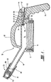
- a dispensing lid 10 for the gravity feed dispensing of a liquid from a container includes a main body 12 defining a cavity 14 and adapted, by means of a screw thread 16, for releasably attaching the lid 10 to the container in a sealing manner.
- a spout 18 extends from the main body 12 and is fitted with an adjustable discharge valve 20 for varying the rate at which liquid can flow through the spout 18.
- An air bleed passage 22 is formed in the lid for enabling fluid communication between the cavity 14 and the external atmosphere.
- the lid 10 also includes a manually operable air bleed valve 24 for selectively opening and closing the air bleed passage 22.
- the air bleed valve 24 is biased to normally close the passage 22 (as shown in Figure 1).
- the lid 10 can be attached to a liquid bearing container by the screw thread 16 and liquid can be dispensed or poured through the spout 18 by action of gravity at a rate dependent on the position or state of the valves 20 and 24.
- the lid 10 is formed with an integral handle 26 so that when the lid 10 is attached to a container the container can be carried and manipulated by the handle 26.
- the air bleed passage 22 is T shaped having a substantially horizontal length 28 and an intersecting substantially vertical length 30.
- the length 28 and 30 are formed in and adjacent the handle 26.
- the passage 22 has a first opening 32 at a lower end of the vertical length 30 that opens onto an under surface of the lid 10.
- a second opening 34 of the passage 22 is provided at an inner most end of the horizontal length 28 adjacent the cavity 14.
- a portion 36 of the horizontal length 28 distant the opening 34 is formed with an increased diameter for housing components of the air bleed valve 24.
- the air bleed valve 24 includes a seal 38 normally biased to seal the second opening 34 and connected via a pin or rod 40 to an actuator in the form of a push button 42.
- the push button 42 is located partially within the portion 36 of the horizontal length 28 and extends therefrom so that it can be operated by the hand gripping the handle 26.
- a spring 44 is also located within the portion 36 and abuts at opposite ends against the button 42 and a shoulder 46 caused by the step wise increase in diameter of the length 28 to form the portion 36. The spring 44 is preloaded so as to bias the seal 38 into a position to seal and close the opening 34.
- a second carry handle 48 is integrally formed over the top of the body 12 to allow easy carrying the lid 10 and a container that may be attached thereto.
- the valve 20 can be turned approximately 180° between a fully closed and a fully opened position to vary the size of the opening of the spout 18 and thus the flow rate of liquid that can be dispensed through the spout 18.
- the valve 20 includes a first part in the form of an outer sleeve 50 that is slidably retained on the outside of the spout 18 and a second part 52 (refer Figure 1 and Figures 5A and 5B) that is attached by way of a screw coupling to an inside wall at the distal end of spout 18.
- Sleeve 50 has a cylindrical main body 54 of an inner diameter marginally greater than the outer diameter of the spout 18.
- a tapered portion 56 Contiguously formed at one end of the main body 54 is a tapered portion 56 that reduces in diameter in a direction away from the spout 18. Formed contiguously with the tapered section 56 is a collar 58 of constant diameter.
- An inclined slot 60 is cut in the main body 54 and is provided at respective opposite ends with restrictions 62A and 62B leading to respective end seats 64A and 64B.
- An axially extending passage 66 is formed on an inside surface of the main body section 54 leading from a lower most edge 68 of the sleeve 50 into the slot 60.
- the second part 52 of the valve 20 has a lower portion 70 of constant diameter formed with a screw thread 72 for threadingly engaging a corresponding thread formed on the inside of the distal end of spout 18.
- a radially extending flange 74 provided with an annular groove for seating an O ring 76.
- Spaced centrally above the flange 74 is a solid disc shaped end 78.
- the end 78 is supported by a pair of inclined arms 80 that are formed integrally with flange 74 and end 78.
- the spacing of the flange 74 and end 78 forms an opening 82 for liquid travelling down the spout 18.
- the end 78 is also formed with an annular groove for seating a further O ring 84.
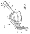
- a short upright pin 86 is formed on the spout 18 (see Figures 1 and 3) for location in the slot 60.
- the second portion 52 is first screwed into the distal end of spout 18 and then the sleeve 50 is slipped onto the outside of the spout 18 with the passage 66 orientated to be in line with the pin 86.
- the height of the pin 86 is designed to be slightly greater than the height or clearance of the passage 66 so that a nominal force must be overcome in order to push the sleeve 50 backwardly over the pin 86 providing a snap type coupling once the pin 86 passes through passage 66 into the slot 60.
- the sleeve 50 is turned so that pin 86 passes through the restriction 62B and into the seat 64B.
- the O ring 74 bears against the inside of the main body 54 just below the commencement of the tapered section 56 and the O ring 84 bears against the inside of the collar 58.
- the opening 82 is effectively sealed preventing the dispensing of liquid from the spout 18.
- the sleeve 50 is rotated on the shaft 18 in a clockwise direction. Due to the engagement of the pin 86 in the slot 60 this causes the sleeve 50 to move in the forward direction as it is rotated. This results in the O ring 84 being spaced below the collar 58 and out of contact with the inside of sleeve 50 allowing liquid to be dispensed through the opening 82.
- the O ring 76 remains in contact with the inside of the main body 54 preventing back flow of liquid between the main body 54 and spout 18 in the direction toward the lower edge 68.
- the valve 20 is releasably locked into the fully opened position by turning the sleeve 52 to the extent that the pin 86 is forced through the restriction 62A and into the seat 64A.
- the lid 10 can be releasably attached to any liquid bearing container having a thread that can mate with the thread 16 formed in the body 12. Therefore the lid 10 can convert a standard container to a gravity feed liquid dispenser. The rate at which liquid can be dispensed can be controlled by the position or states of the valves 20 and 24. It will be appreciated that provided the lid 10 is attached to the container in the sealing manner then even if the valve 20 is open and the lid 10 and container is knocked over there will be no or minimal escape of liquid because the air bleed valve 24 will be automatically held shut. Consequently, there cannot be an equalisation of air pressure inside and outside of the container and therefore depending on how full the container originally was no or only a limited amount of liquid will be able to escape.
- the lid 10 is particularly useful for incorporation into a liquid dispensing system comprising say a number of liquid containers formed with necks having a thread complimentary to the screw thread 16 and normally closed by way of screw caps. In such a system, the lid 10 can be screwed onto a container and used to dispense the liquid from that container. Once the container is empty the lid 10 can be unscrewed from that container and screwed onto another full container.
- lid 10 enables any container to be converted into a controllable gravity feed dispenser, with the lid allowing separate independent regulation of both liquid discharge and air bleeding.
- the lid 10 can be provided with any type of mating or fastening system for attaching to a container including a snap fitting, bayonet fitting or even a push or press fit. Further the means for attaching the lid to the container can be formed external of the cavity 14 rather than internal as shown in Figure 1. Also, the first opening 32 of the air bleed passage can be formed at a location other than on an under surface of the lid 10. However this location is selected in the preferred embodiment as it decreases the likelihood of ingress of dirt or other foreign matter into the passage 22.
Abstract
Description
- Figure 1
- is a cross sectional view of an embodiment of the present invention;
- Figure 2
- is a bottom view of the lid shown in Figure 1;
- Figure 3
- is a perspective view of the lid shown in Figures 1 and 2;
- Figure 4A
- is a side view of one part of a dispensing valve of the lid shown in Figures 1 and 2;
- Figure 4B
- is a bottom view of the first part of the valve shown in Figure 4A;
- Figure 5A
- is a side view of a second part of the dispensing valve of the lid shown in Figures 1 and 2; and,
- Figure 5B
- is a bottom end view of the second part of the valve shown in Figure 5A.
Claims (7)
- A dispensing lid (10) for the gravity feed dispensing of a liquid from a container, the lid (10) comprising:a main body (12) defining a cavity (14) and having coupling means (16) for releasably attaching the lid (10) to the container in a sealing manner;an air bleed passage (22) enabling fluid communication between said cavity (14) and the atmosphere and a manually operable air bleed valve (24) for selectively opening and closing said air bleed passage (22), said air bleed valve being biased to a closed position that seals the air bleed passage; anda spout (18) extending from the main body (12), the spout (18) having an outer surface and a discharge opening at a distal end,the lid being characterised in that the spout (18) further includes a pin (86) being provided on the outer surface and an adjustable discharge valve (20) coupled to the spout (18) for varying the flow rate of liquid through the spout (18), the discharge valve (20) and air bleed valve (24) being separately controllable, and the adjustable discharge valve (20) including:a first part (50) comprising a sleeve having a cylindrical main body (54) with first and second opposite axial ends; a tapered portion (56) continuous with the second axial end and reducing in diameter away from the first axial end, and a collar (58) of constant diameter formed contiguously with the tapered portion (56), with an inclined slot (60) formed in the cylindrical portion and in which said pin (86) resides, the slot (60) having an upper end axially spaced from the second axial end of said cylindrical portion; anda second part (52) coupled to the discharge opening, the second part provided with an opening (82) and first and second seals on opposite sides of the opening, the first seal (76) forming a seal with an inside surface of the cylindrical portion (54) of the first part (50) between the upper end (64B) of the slot (60) and the second axial end of the cylindrical portion (54), and the second seal (84) forming a seal with an inside surface of said collar (58).
- The lid according to Claim 1 characterised by said second part (52) including a lower portion (70) of constant diameter coupled to the discharge opening, a pair of inclined arms (80) extending toward each other and away from said lower portion (70), and a disc (78) supported by said arms (80) distant said lower portion (70), said disc (78) extending in a plane transverse to an axis of said lower portion, said first seal (76) being provided circumferentially about said lower portion (70) and said second seal (84) being provided circumferentially about said disc (78).
- The lid according to Claim 1 or Claim 2 characterised by said air bleed passage (22) having a first opening (32) that opens onto an undersurface of the lid.
- The lid according to Claim 3 characterised by said air bleed passage (22) having a second opening (34) that opens onto said cavity (14) and said air bleed valve (24) includes a seal (38) normally biased to seal the second opening (34) and connected with a manually operable actuator (42).
- The lid according to Claim 4 characterised by said seal (38) being connected to the actuator (42) via an elongated pin (40) and the actuator (42) being in the form of a button that can be depressed to open the seal (38) against the bias to allow air to bleed into a container to which the lid is attached via the air bleed passage (22).
- The lid according to any one of Claims 1-5 characterised by a handle (26) so that when the lid is attached to a container, the container can be carried and manipulated by the handle.
- The lid according to Claim 6 characterised by said actuator (42) being disposed in said handle (26) to allow the air bleed valve (24) to be operated by a hand gripping the handle (26).
Applications Claiming Priority (3)
| Application Number | Priority Date | Filing Date | Title |
|---|---|---|---|
| AUPP600398 | 1998-09-17 | ||
| AUPP6003A AUPP600398A0 (en) | 1998-09-17 | 1998-09-17 | Dispensing lid |
| PCT/AU1999/000756 WO2000017091A1 (en) | 1998-09-17 | 1999-09-13 | Dispensing lid |
Publications (4)
| Publication Number | Publication Date |
|---|---|
| EP1121323A1 EP1121323A1 (en) | 2001-08-08 |
| EP1121323A4 EP1121323A4 (en) | 2002-08-14 |
| EP1121323B1 true EP1121323B1 (en) | 2005-06-01 |
| EP1121323B8 EP1121323B8 (en) | 2005-08-24 |
Family
ID=3810219
Family Applications (1)
| Application Number | Title | Priority Date | Filing Date |
|---|---|---|---|
| EP99945769A Expired - Lifetime EP1121323B8 (en) | 1998-09-17 | 1999-09-13 | Dispensing lid |
Country Status (17)
| Country | Link |
|---|---|
| US (1) | US6364176B1 (en) |
| EP (1) | EP1121323B8 (en) |
| JP (1) | JP3578715B2 (en) |
| KR (1) | KR100518165B1 (en) |
| CN (1) | CN1112316C (en) |
| AT (1) | ATE296783T1 (en) |
| AU (1) | AUPP600398A0 (en) |
| BR (1) | BR9913879A (en) |
| CA (1) | CA2354767C (en) |
| DE (1) | DE69925620T2 (en) |
| ES (1) | ES2245514T3 (en) |
| MX (1) | MXPA01002816A (en) |
| NO (1) | NO20011305L (en) |
| NZ (1) | NZ511111A (en) |
| PL (1) | PL190154B1 (en) |
| WO (1) | WO2000017091A1 (en) |
| ZA (1) | ZA200103060B (en) |
Families Citing this family (21)
| Publication number | Priority date | Publication date | Assignee | Title |
|---|---|---|---|---|
| GB0015599D0 (en) * | 2000-06-27 | 2000-08-16 | White Matthew E T | Liquid-pourers |
| US8939324B2 (en) * | 2006-07-05 | 2015-01-27 | Kazem Azodi | Fizz retaining device for beverage containers |
| GB0622974D0 (en) * | 2006-11-17 | 2006-12-27 | Carbonite Corp | Dispensing caps for beverage containers |
| GB2448296A (en) * | 2007-04-13 | 2008-10-15 | Ilan Zadik Samson | Cap for a Spill-Proof Beverage Container |
| US8220671B2 (en) * | 2008-03-12 | 2012-07-17 | Trico Corporation | Lubricant dispenser with nozzle |
| KR101142574B1 (en) * | 2010-06-11 | 2012-05-11 | 이광무 | The liquid container that discharge control is possible |
| CN102838076A (en) * | 2011-06-23 | 2012-12-26 | 可口可乐公司 | Close over assembly and beverage distributor provided with same |
| GB2497781B (en) * | 2011-12-20 | 2014-02-12 | Ben Tagoe | Liquid pourer |
| US8950637B2 (en) | 2012-08-28 | 2015-02-10 | Conrad H. Wilkins | Valved fluid transport container |
| CN103662360A (en) * | 2013-12-17 | 2014-03-26 | 李健 | Experiment sealing cover |
| US9884148B2 (en) | 2014-05-30 | 2018-02-06 | Neilmed Pharmaceuticals, Inc. | Angular cap for dispensing liquids |
| EP3197521B1 (en) * | 2014-09-22 | 2021-01-27 | Ketan C. Mehta | Angular cap for dispensing liquids |
| US10308405B2 (en) * | 2014-11-26 | 2019-06-04 | Des-Case Corporation | Oil dispensing lid |
| WO2016128718A1 (en) | 2015-02-13 | 2016-08-18 | Nerudia Ltd | System and assembly |
| GB2535239A (en) | 2015-02-13 | 2016-08-17 | Nerudia Ltd | System and apparatus |
| PL3409597T3 (en) | 2015-02-13 | 2019-12-31 | Fontem Holdings 1 B.V. | Filling system for electronic smoking devices |
| GB2535982A (en) | 2015-02-13 | 2016-09-07 | Nerudia Ltd | System and apparatus |
| CN105502260A (en) * | 2015-12-24 | 2016-04-20 | 张玉红 | Accelerator capable of preventing splashing of liquid poured out of container |
| CA3028492A1 (en) * | 2018-12-21 | 2020-06-21 | Le Groupe Dsd Inc. | Vented spout for a liquid storage container |
| US11104493B1 (en) | 2020-11-16 | 2021-08-31 | Stephen Cox | Pouring spout assembly |
| CN112875034B (en) * | 2021-01-25 | 2022-10-21 | 浙江诺维雅工贸有限公司 | Cover body of container |
Family Cites Families (27)
| Publication number | Priority date | Publication date | Assignee | Title |
|---|---|---|---|---|
| DE205898C (en) * | ||||
| US442638A (en) * | 1890-12-16 | John a | ||
| US705160A (en) * | 1902-03-04 | 1902-07-22 | John Albert Swanson | Oil-can spout. |
| US1072588A (en) * | 1912-08-14 | 1913-09-09 | William T Duncan | Milk-can container and milk-server. |
| US1373244A (en) * | 1919-08-22 | 1921-03-29 | Hernandez Francisco | Oil-can |
| US1357024A (en) * | 1920-03-15 | 1920-10-26 | Marcus B Behrman | Collapsible tube and other container |
| US1771106A (en) * | 1925-10-31 | 1930-07-22 | Alva O Wright | Dispensing receptacle |
| US1904739A (en) * | 1932-07-08 | 1933-04-18 | August F Kroen | Closure for containers |
| US2160976A (en) * | 1937-06-22 | 1939-06-06 | Mirati John | Can holding and liquid dispensing device |
| US2254164A (en) * | 1939-08-25 | 1941-08-26 | Bernhardt Rudolph | Server or pitcher |
| US2306550A (en) * | 1941-02-26 | 1942-12-29 | Carl F Mailey | Combination cover and dispensing device for canned milk |
| US2799437A (en) * | 1954-10-18 | 1957-07-16 | Jepson Percy | Separator for use in separating liquids of different specific gravity |
| US3278096A (en) * | 1964-12-28 | 1966-10-11 | Formold Plastics Inc | Combination cap for containers |
| US4069946A (en) * | 1977-01-03 | 1978-01-24 | Justrite Manufacturing Company | Consumer safety container for inflammables |
| DE3632991A1 (en) * | 1986-09-29 | 1988-03-31 | Goldmann Wolfgang | Pouring accessory for bottled ale or bottled weiss beer |
| US4746036A (en) | 1987-02-02 | 1988-05-24 | Messner Marvin M | Gasoline container |
| US4928856A (en) * | 1987-03-11 | 1990-05-29 | White Jonathan Z | Bottled water dispensing system |
| US5249611A (en) * | 1987-03-16 | 1993-10-05 | Vemco, Inc. | Pour spout |
| US4946079A (en) * | 1988-07-21 | 1990-08-07 | Campbell John T | Vented and valved pouring spout |
| US4966481A (en) * | 1988-07-27 | 1990-10-30 | Robert Satten | Cleaning fluid dispenser and applicator |
| US5000360A (en) * | 1989-09-27 | 1991-03-19 | John Lown | Pouring spout which can be selectively opened and closed |
| AU685110B2 (en) * | 1993-07-08 | 1998-01-15 | Monsanto Europe S.A. | Improved closure for liquid containing containers |
| US5405058A (en) | 1994-02-01 | 1995-04-11 | Kalis; Russell A. | Device for dispensing liquids |
| US5477994A (en) | 1994-06-20 | 1995-12-26 | Rubbermaid Incorporated | Beverage container valve |
| US5477980A (en) * | 1994-12-08 | 1995-12-26 | Chaffin; Jeffrey D. | Receptacle cover with valve controlled openings |
| US5775550A (en) * | 1995-06-30 | 1998-07-07 | Toll; Duncan M. | Gravity dispenser with improved shut-off feature |
| US5615808A (en) | 1996-05-21 | 1997-04-01 | Huang; Frank T.-H. | Teapot |
-
1998
- 1998-09-17 AU AUPP6003A patent/AUPP600398A0/en not_active Abandoned
-
1999
- 1999-09-13 EP EP99945769A patent/EP1121323B8/en not_active Expired - Lifetime
- 1999-09-13 WO PCT/AU1999/000756 patent/WO2000017091A1/en active IP Right Grant
- 1999-09-13 KR KR10-2001-7003490A patent/KR100518165B1/en not_active IP Right Cessation
- 1999-09-13 ES ES99945769T patent/ES2245514T3/en not_active Expired - Lifetime
- 1999-09-13 MX MXPA01002816A patent/MXPA01002816A/en not_active IP Right Cessation
- 1999-09-13 CA CA002354767A patent/CA2354767C/en not_active Expired - Fee Related
- 1999-09-13 JP JP2000574010A patent/JP3578715B2/en not_active Expired - Fee Related
- 1999-09-13 AT AT99945769T patent/ATE296783T1/en not_active IP Right Cessation
- 1999-09-13 PL PL99346659A patent/PL190154B1/en not_active IP Right Cessation
- 1999-09-13 NZ NZ511111A patent/NZ511111A/en unknown
- 1999-09-13 CN CN99811077A patent/CN1112316C/en not_active Expired - Fee Related
- 1999-09-13 BR BR9913879-4A patent/BR9913879A/en active Search and Examination
- 1999-09-13 DE DE69925620T patent/DE69925620T2/en not_active Expired - Fee Related
- 1999-09-17 US US09/398,247 patent/US6364176B1/en not_active Expired - Lifetime
-
2001
- 2001-03-15 NO NO20011305A patent/NO20011305L/en not_active Application Discontinuation
- 2001-04-12 ZA ZA200103060A patent/ZA200103060B/en unknown
Also Published As
| Publication number | Publication date |
|---|---|
| EP1121323B8 (en) | 2005-08-24 |
| WO2000017091A1 (en) | 2000-03-30 |
| ATE296783T1 (en) | 2005-06-15 |
| MXPA01002816A (en) | 2002-04-08 |
| DE69925620D1 (en) | 2005-07-07 |
| US6364176B1 (en) | 2002-04-02 |
| PL190154B1 (en) | 2005-11-30 |
| CN1112316C (en) | 2003-06-25 |
| AUPP600398A0 (en) | 1998-10-08 |
| ZA200103060B (en) | 2002-08-28 |
| EP1121323A1 (en) | 2001-08-08 |
| CA2354767A1 (en) | 2000-03-30 |
| NO20011305L (en) | 2001-05-02 |
| JP3578715B2 (en) | 2004-10-20 |
| PL346659A1 (en) | 2002-02-25 |
| EP1121323A4 (en) | 2002-08-14 |
| NZ511111A (en) | 2002-10-25 |
| JP2002526342A (en) | 2002-08-20 |
| ES2245514T3 (en) | 2006-01-01 |
| BR9913879A (en) | 2001-11-27 |
| DE69925620T2 (en) | 2006-04-27 |
| KR20010079855A (en) | 2001-08-22 |
| CA2354767C (en) | 2008-02-26 |
| KR100518165B1 (en) | 2005-09-30 |
| NO20011305D0 (en) | 2001-03-15 |
| CN1318031A (en) | 2001-10-17 |
Similar Documents
| Publication | Publication Date | Title |
|---|---|---|
| EP1121323B1 (en) | Dispensing lid | |
| CA1302367C (en) | Container closure cap with metering appliance | |
| EP1212257B1 (en) | Non-spilling detachable pouring spout | |
| US6227419B1 (en) | Spout | |
| EP1324943B1 (en) | Fluid dispensing closure | |
| US6968983B2 (en) | Closed loop dispensing system | |
| US5988456A (en) | Closed loop dispensing system | |
| US6435380B1 (en) | Self-sealed spout | |
| US5975164A (en) | Nozzle for dispensing container and receptacle for receiving same | |
| EP1646580B2 (en) | Retractable spout assembly for bottles | |
| EP0963324B1 (en) | Dispensing closure | |
| US5678737A (en) | Vented liquid dispenser and attachment cap therefor | |
| US6269984B1 (en) | Dispensing stopper for a bottle | |
| US10494153B2 (en) | Method and apparatus for controlled transfer of fluid | |
| US6702160B1 (en) | No spill container | |
| US6481601B1 (en) | Self-sealing solvent bottle cap insert | |
| US20120211514A1 (en) | Method for removing fluid from pressurized container | |
| US5620117A (en) | Exchangeable closing and pouring cap | |
| AU757531B2 (en) | Dispensing lid | |
| US5799839A (en) | Dual spout stopper | |
| EP0298247A1 (en) | Closing device for liquid bottles | |
| EP0213783A1 (en) | Tap for a liquid container | |
| US11077994B2 (en) | Method and apparatus for controlled transfer of fluid | |
| US3450315A (en) | Liquid dispensing container having a gravity actuated closure |
Legal Events
| Date | Code | Title | Description |
|---|---|---|---|
| PUAI | Public reference made under article 153(3) epc to a published international application that has entered the european phase |
Free format text: ORIGINAL CODE: 0009012 |
|
| 17P | Request for examination filed |
Effective date: 20010418 |
|
| AK | Designated contracting states |
Kind code of ref document: A1 Designated state(s): AT BE CH CY DE DK ES FI FR GB GR IE IT LI LU MC NL PT SE |
|
| RAP1 | Party data changed (applicant data changed or rights of an application transferred) |
Owner name: OIL SAFE SYSTEMS PTY LTD |
|
| RIN1 | Information on inventor provided before grant (corrected) |
Inventor name: OIL SAFE SYSTEMS PTY LTD |
|
| A4 | Supplementary search report drawn up and despatched |
Effective date: 20020703 |
|
| AK | Designated contracting states |
Kind code of ref document: A4 Designated state(s): AT BE CH CY DE DK ES FI FR GB GR IE IT LI LU MC NL PT SE |
|
| 17Q | First examination report despatched |
Effective date: 20021018 |
|
| GRAP | Despatch of communication of intention to grant a patent |
Free format text: ORIGINAL CODE: EPIDOSNIGR1 |
|
| GRAS | Grant fee paid |
Free format text: ORIGINAL CODE: EPIDOSNIGR3 |
|
| GRAA | (expected) grant |
Free format text: ORIGINAL CODE: 0009210 |
|
| AK | Designated contracting states |
Kind code of ref document: B1 Designated state(s): AT BE CH CY DE DK ES FI FR GB GR IE IT LI LU MC NL PT SE |
|
| PG25 | Lapsed in a contracting state [announced via postgrant information from national office to epo] |
Ref country code: NL Free format text: LAPSE BECAUSE OF FAILURE TO SUBMIT A TRANSLATION OF THE DESCRIPTION OR TO PAY THE FEE WITHIN THE PRESCRIBED TIME-LIMIT Effective date: 20050601 Ref country code: LI Free format text: LAPSE BECAUSE OF FAILURE TO SUBMIT A TRANSLATION OF THE DESCRIPTION OR TO PAY THE FEE WITHIN THE PRESCRIBED TIME-LIMIT Effective date: 20050601 Ref country code: FI Free format text: LAPSE BECAUSE OF FAILURE TO SUBMIT A TRANSLATION OF THE DESCRIPTION OR TO PAY THE FEE WITHIN THE PRESCRIBED TIME-LIMIT Effective date: 20050601 Ref country code: CH Free format text: LAPSE BECAUSE OF FAILURE TO SUBMIT A TRANSLATION OF THE DESCRIPTION OR TO PAY THE FEE WITHIN THE PRESCRIBED TIME-LIMIT Effective date: 20050601 Ref country code: BE Free format text: LAPSE BECAUSE OF FAILURE TO SUBMIT A TRANSLATION OF THE DESCRIPTION OR TO PAY THE FEE WITHIN THE PRESCRIBED TIME-LIMIT Effective date: 20050601 Ref country code: AT Free format text: LAPSE BECAUSE OF FAILURE TO SUBMIT A TRANSLATION OF THE DESCRIPTION OR TO PAY THE FEE WITHIN THE PRESCRIBED TIME-LIMIT Effective date: 20050601 |
|
| REG | Reference to a national code |
Ref country code: GB Ref legal event code: FG4D |
|
| REG | Reference to a national code |
Ref country code: CH Ref legal event code: EP |
|
| REG | Reference to a national code |
Ref country code: IE Ref legal event code: FG4D |
|
| REF | Corresponds to: |
Ref document number: 69925620 Country of ref document: DE Date of ref document: 20050707 Kind code of ref document: P |
|
| RIN2 | Information on inventor provided after grant (corrected) |
Inventor name: KILIAN, MICHAEL |
|
| PG25 | Lapsed in a contracting state [announced via postgrant information from national office to epo] |
Ref country code: SE Free format text: LAPSE BECAUSE OF FAILURE TO SUBMIT A TRANSLATION OF THE DESCRIPTION OR TO PAY THE FEE WITHIN THE PRESCRIBED TIME-LIMIT Effective date: 20050901 Ref country code: GR Free format text: LAPSE BECAUSE OF FAILURE TO SUBMIT A TRANSLATION OF THE DESCRIPTION OR TO PAY THE FEE WITHIN THE PRESCRIBED TIME-LIMIT Effective date: 20050901 Ref country code: DK Free format text: LAPSE BECAUSE OF FAILURE TO SUBMIT A TRANSLATION OF THE DESCRIPTION OR TO PAY THE FEE WITHIN THE PRESCRIBED TIME-LIMIT Effective date: 20050901 |
|
| PG25 | Lapsed in a contracting state [announced via postgrant information from national office to epo] |
Ref country code: IE Free format text: LAPSE BECAUSE OF NON-PAYMENT OF DUE FEES Effective date: 20050913 Ref country code: CY Free format text: LAPSE BECAUSE OF FAILURE TO SUBMIT A TRANSLATION OF THE DESCRIPTION OR TO PAY THE FEE WITHIN THE PRESCRIBED TIME-LIMIT Effective date: 20050913 |
|
| PGFP | Annual fee paid to national office [announced via postgrant information from national office to epo] |
Ref country code: GB Payment date: 20050914 Year of fee payment: 7 |
|
| PGFP | Annual fee paid to national office [announced via postgrant information from national office to epo] |
Ref country code: DE Payment date: 20050922 Year of fee payment: 7 |
|
| PGFP | Annual fee paid to national office [announced via postgrant information from national office to epo] |
Ref country code: FR Payment date: 20050927 Year of fee payment: 7 |
|
| PG25 | Lapsed in a contracting state [announced via postgrant information from national office to epo] |
Ref country code: MC Free format text: LAPSE BECAUSE OF NON-PAYMENT OF DUE FEES Effective date: 20050930 Ref country code: LU Free format text: LAPSE BECAUSE OF NON-PAYMENT OF DUE FEES Effective date: 20050930 |
|
| PGFP | Annual fee paid to national office [announced via postgrant information from national office to epo] |
Ref country code: ES Payment date: 20051014 Year of fee payment: 7 |
|
| PG25 | Lapsed in a contracting state [announced via postgrant information from national office to epo] |
Ref country code: PT Free format text: LAPSE BECAUSE OF FAILURE TO SUBMIT A TRANSLATION OF THE DESCRIPTION OR TO PAY THE FEE WITHIN THE PRESCRIBED TIME-LIMIT Effective date: 20051103 |
|
| NLV1 | Nl: lapsed or annulled due to failure to fulfill the requirements of art. 29p and 29m of the patents act | ||
| REG | Reference to a national code |
Ref country code: CH Ref legal event code: PL |
|
| REG | Reference to a national code |
Ref country code: ES Ref legal event code: FG2A Ref document number: 2245514 Country of ref document: ES Kind code of ref document: T3 |
|
| PLBE | No opposition filed within time limit |
Free format text: ORIGINAL CODE: 0009261 |
|
| STAA | Information on the status of an ep patent application or granted ep patent |
Free format text: STATUS: NO OPPOSITION FILED WITHIN TIME LIMIT |
|
| ET | Fr: translation filed | ||
| 26N | No opposition filed |
Effective date: 20060302 |
|
| REG | Reference to a national code |
Ref country code: IE Ref legal event code: MM4A |
|
| PGFP | Annual fee paid to national office [announced via postgrant information from national office to epo] |
Ref country code: IT Payment date: 20060930 Year of fee payment: 8 |
|
| PG25 | Lapsed in a contracting state [announced via postgrant information from national office to epo] |
Ref country code: DE Free format text: LAPSE BECAUSE OF NON-PAYMENT OF DUE FEES Effective date: 20070403 |
|
| GBPC | Gb: european patent ceased through non-payment of renewal fee |
Effective date: 20060913 |
|
| REG | Reference to a national code |
Ref country code: FR Ref legal event code: ST Effective date: 20070531 |
|
| PG25 | Lapsed in a contracting state [announced via postgrant information from national office to epo] |
Ref country code: GB Free format text: LAPSE BECAUSE OF NON-PAYMENT OF DUE FEES Effective date: 20060913 |
|
| REG | Reference to a national code |
Ref country code: ES Ref legal event code: FD2A Effective date: 20060914 |
|
| PG25 | Lapsed in a contracting state [announced via postgrant information from national office to epo] |
Ref country code: ES Free format text: LAPSE BECAUSE OF NON-PAYMENT OF DUE FEES Effective date: 20060914 |
|
| PG25 | Lapsed in a contracting state [announced via postgrant information from national office to epo] |
Ref country code: FR Free format text: LAPSE BECAUSE OF NON-PAYMENT OF DUE FEES Effective date: 20061002 |
|
| PG25 | Lapsed in a contracting state [announced via postgrant information from national office to epo] |
Ref country code: IT Free format text: LAPSE BECAUSE OF NON-PAYMENT OF DUE FEES Effective date: 20070913 |