EP1120942A2 - Demodulator with automatic quadrature control - Google Patents
Demodulator with automatic quadrature control Download PDFInfo
- Publication number
- EP1120942A2 EP1120942A2 EP01101648A EP01101648A EP1120942A2 EP 1120942 A2 EP1120942 A2 EP 1120942A2 EP 01101648 A EP01101648 A EP 01101648A EP 01101648 A EP01101648 A EP 01101648A EP 1120942 A2 EP1120942 A2 EP 1120942A2
- Authority
- EP
- European Patent Office
- Prior art keywords
- quadrature
- signal
- output
- component
- error
- Prior art date
- Legal status (The legal status is an assumption and is not a legal conclusion. Google has not performed a legal analysis and makes no representation as to the accuracy of the status listed.)
- Granted
Links
Images






Classifications
-
- H—ELECTRICITY
- H04—ELECTRIC COMMUNICATION TECHNIQUE
- H04L—TRANSMISSION OF DIGITAL INFORMATION, e.g. TELEGRAPHIC COMMUNICATION
- H04L27/00—Modulated-carrier systems
- H04L27/0014—Carrier regulation
-
- H—ELECTRICITY
- H04—ELECTRIC COMMUNICATION TECHNIQUE
- H04L—TRANSMISSION OF DIGITAL INFORMATION, e.g. TELEGRAPHIC COMMUNICATION
- H04L27/00—Modulated-carrier systems
- H04L27/0014—Carrier regulation
- H04L2027/0016—Stabilisation of local oscillators
-
- H—ELECTRICITY
- H04—ELECTRIC COMMUNICATION TECHNIQUE
- H04L—TRANSMISSION OF DIGITAL INFORMATION, e.g. TELEGRAPHIC COMMUNICATION
- H04L27/00—Modulated-carrier systems
- H04L27/0014—Carrier regulation
- H04L2027/0024—Carrier regulation at the receiver end
Definitions
- the demodulation circuit adjusted manually in an analog fashion, is liable to degradation due to temperature or humidity of the analog components, while being liable to deterioration with lapse of time, resulting in that quadrature properties cannot be maintained for prolonged time.
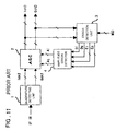
- Fig. 11 shows a structure of a conventional demodulator.
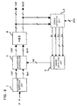
- the quadrature-detecting unit 1 demodulates input quadrature modulated signals, as IF (intermediate frequency) signals, into baseband signals Ich1 and Qch1. Meanwhile, the quadrature-detecting unit 1 is made up of known detection circuits, such as a synchronous detection circuit, a sub (or quasi)-synchronous circuit and/or a delay detection circuit.
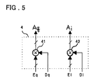
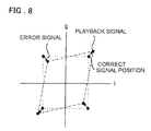
- the signal point error signals Ei, Eq, obtained by the error detection unit 3, and the polarity signals Di, Dq, indicate whether the reproduced signal is deviated from the regular signal point position in the positive direction or in the negative direction.
- these signals need to be converted into quadrature error (deviation) signals.
Landscapes
- Engineering & Computer Science (AREA)
- Computer Networks & Wireless Communication (AREA)
- Signal Processing (AREA)
- Digital Transmission Methods That Use Modulated Carrier Waves (AREA)
- Control Of Amplification And Gain Control (AREA)
Abstract
Description
It is another object of the present invention, to provide a demodulator which renders it unnecessary to make precision adjustment on the modulator side and which assures operational stability and high reliability without producing deterioration in characteristics such as error rate for a prolonged time.
Further objects of the present invention will become apparent in the entire disclosure.
a quadrature controller for correcting quadrature errors of a signal quadrature-detected by a quadrature detecting unit, and a quadrature error detection unit for detecting a quadrature error based on an error signal detected as to in-phase and quadrature components from a demodulated signal output from an automatic gain controller fed with an input signal corrected for quadrature errors as an output signal of the quadrature controller, to feed the detected quadrature error (signal) to the quadrature controller.

Claims (8)
- A demodulator comprising:(a) a quadrature controller fed with a signal quadrature-detected by a quadrature detecting unit as an input signal to correct a quadrature error between phases of an in-phase component and a quadrature component of said signal based on a quadrature error signal used for correcting said quadrature error to output a corrected signal;(b) an error detection unit detecting an error signal between the in-phase component and the quadrature component of a demodulated signal output by an automatic gain controller fed with an output signal of said quadrature controller corrected for quadrature error; and(c) a quadrature error detection unit detecting the quadrature error based on said error signal to feed the quadrature error signal to said quadrature controller.
- A demodulator comprising:(a) a quadrature detecting unit fed with and quadrature-detecting a quadrature modulated signal to output an in-phase component and a quadrature component;(b) a quadrature controller fed with the in-phase component and the quadrature component output from said quadrature detecting unit, said quadrature controller correcting the quadrature error between the in-phase component and the quadrature component based on an input quadrature error signal, and outputting the resulting signal;(c) an automatic gain controller fed with the in-phase component and the quadrature component output from said quadrature controller and outputting signals corrected for amplitude errors based on the input amplitude error signal as the in-phase component and the quadrature component of a demodulated signal;(d) an error detection unit detecting, from the in-phase component and the quadrature component of the demodulated signal output from said automatic gain controller, an in-phase component of said error signal and a polarity signal of the in-phase component of the demodulated signal, and a quadrature component of the error signal and a polarity signal of the quadrature component of said demodulated signal;(e) an amplitude error detection unit generating an in-phase component and a quadrature component of an amplitude error signal based on the in-phase component of said error signal output from said error detection unit and the polarity signal of the in-phase component of the demodulated signal, and on the quadrature component of the error signal and the polarity signal of the quadrature component of said demodulated signal, to output the generated in-phase and quadrature components of said amplitude error signal to said automatic gain controller; and(f) a quadrature error detection unit generating a quadrature error signal based on the in-phase component of the error signal and the polarity signal of the in-phase component of said demodulated signal, both output from said error detection unit, and on the in-phase component of said error signal and the polarity signal of the quadrature component of said demodulated signal to feed the generated quadrature error signal to said quadrature controller.
- A demodulator comprising:(a) an quadrature detecting unit fed with a Quadrature modulated signal as an input signal to quadrature-detect the input signal to output in-phase and quadrature components of a regular amplitude;(b) a quadrature controller fed with the in-phase and quadrature components output from the quadrature detection unit to correct the quadrature error between phases of the in-phase and quadrature components, based a quadrature error signal;(c) an automatic gain controller fed with the in-phase and quadrature components output from said quadrature controller to output signals corrected for respective amplitude errors as in-phase and quadrature components of a demodulated signal;(d) an error detection unit detecting an in-phase component of an error signal and a polarity signal of the in-phase component of the demodulated signal, and a quadrature component of the error signal and a polarity signal of the quadrature component of the demodulated signal, from the in-phase and quadrature components of the demodulated signal output from the automatic gain controller; and(e) a quadrature error detection unit generating a quadrature error signal based on the in-phase component of the error signal and the polarity signal of the in-phase component of the demodulated signal, and the quadrature component of the error signal and a polarity signal of the quadrature component of the demodulated signal, all output from said error detection unit, to feed the generated quadrature error signal to said quadrature controller.
- The demodulator as defined in claim 2 or 3 wherein
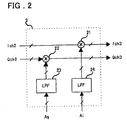
said quadrature controller comprises;a first low-pass filter fed with said quadrature error signal output from said quadrature error detection unit to smooth out and output said quadrature error signal;a first multiplier multiplying the quadrature component output from said quadrature detecting unit with an output of said first low-pass filter; anda first adder adding the in-phase component output from said quadrature detecting unit and an output of said first multiplier;the quadrature component output from said quadrature detecting unit being directly output, an output of said first adder being output as an in-phase component corrected for quadrature errors. - The demodulator as defined in claim 2 or 3 wherein said quadrature error detection unit comprises;a second multiplier multiplying the in-phase component of the error signal (Ei) output from said quadrature detecting unit with the polarity signal (Dq) of the quadrature component of said demodulated signal;a third multiplier multiplying the quadrature component of the error signal (Eq) output from said quadrature detecting unit with the polarity signal (Di) of the in-phase component of said demodulated signal; anda second adder summing outputs of said second and third multipliers;an output signal of said second adder being output as said quadrature error signal (Qd).
- The demodulator as defined in claim 2 wherein said automatic gain controller comprises;a second low-pass filter smoothing out and outputting the in-phase component of the amplitude error signal output from said amplitude error detection unit;a third low-pass filter smoothing out and outputting the quadrature component of the amplitude error signal output from said amplitude error detection unit;a fourth multiplier multiplying the in-phase component output from said quadrature controller as an input signal with an in-phase component of the amplitude error signal smoothed out by said second low-pass filter, said fourth multiplier outputting the result of multiplication as the in-phase component of the demodulated signal; anda fifth multiplier multiplying the quadrature component output from said quadrature controller as an input signal with a quadrature component of the amplitude error signal smoothed out by said third low-pass filter, said fifth multiplier outputting the result of multiplication as the quadrature component of the demodulated signal.
- The demodulator as defined in claim 3 wherein said automatic gain controller comprises;a first absolute value computing circuit determining an absolute value of the in-phase component output from said quadrature controller;a second absolute value computing circuit determining an absolute value of the quadrature component output from said quadrature controller;a third adder adding together outputs from the first and second absolute value computing circuits;a fourth low pass filter smoothing out an output of the third adder;a sixth multiplier multiplying an in-phase component output from said quadrature controller with an output of the fourth low pass filter; andwherein the quadrature component output from the quadrature controller is directly output as the quadrature component, and an output of the sixth multiplier is output as the in-phase component of the demodulated signal.
- A method of using a demodulator according to any of claims 1 to 7.
Applications Claiming Priority (2)
| Application Number | Priority Date | Filing Date | Title |
|---|---|---|---|
| JP2000017069 | 2000-01-26 | ||
| JP2000017069A JP3371876B2 (en) | 2000-01-26 | 2000-01-26 | Demodulator with automatic quadrature control function |
Publications (3)
| Publication Number | Publication Date |
|---|---|
| EP1120942A2 true EP1120942A2 (en) | 2001-08-01 |
| EP1120942A3 EP1120942A3 (en) | 2004-01-07 |
| EP1120942B1 EP1120942B1 (en) | 2014-09-03 |
Family
ID=18544107
Family Applications (1)
| Application Number | Title | Priority Date | Filing Date |
|---|---|---|---|
| EP01101648.2A Expired - Lifetime EP1120942B1 (en) | 2000-01-26 | 2001-01-26 | Demodulator with automatic quadrature control |
Country Status (4)
| Country | Link |
|---|---|
| US (1) | US7031399B2 (en) |
| EP (1) | EP1120942B1 (en) |
| JP (1) | JP3371876B2 (en) |
| CA (1) | CA2332205C (en) |
Families Citing this family (16)
| Publication number | Priority date | Publication date | Assignee | Title |
|---|---|---|---|---|
| CN1717883B (en) * | 2002-11-27 | 2012-05-09 | Rgb网络有限公司 | Method and apparatus for time-multiplexed processing of multiple digital video programs |
| EP1616401A4 (en) * | 2003-04-21 | 2012-01-04 | Rgb Networks Inc | Time-multiplexed multi-program encryption system |
| CN100589475C (en) * | 2003-04-21 | 2010-02-10 | Rgb网络有限公司 | Broadband Multi-channel Quadrature Amplitude Modulation of CATV Signals |
| US7110477B2 (en) * | 2003-04-29 | 2006-09-19 | Texas Instruments Incorporated | Gaussian frequency shift keying digital demodulator |
| CA2537280C (en) | 2003-08-29 | 2014-04-01 | Rgb Networks, Inc. | Advanced, self-balancing video multiplexer system |
| US20060007999A1 (en) * | 2004-07-08 | 2006-01-12 | Gomez Ramon A | Method and system for enhancing image rejection in communications receivers using test tones and a baseband equalizer |
| US7773693B2 (en) * | 2004-10-07 | 2010-08-10 | Samsung Electronics Co., Ltd. | Apparatus and method for direct quadrature power amplifier modulation |
| JP4793566B2 (en) * | 2006-03-22 | 2011-10-12 | 日本電気株式会社 | Wireless communication apparatus and wireless communication method |
| US8654885B2 (en) | 2006-06-06 | 2014-02-18 | Qualcomm Incorporated | Fast in-phase and quadrature imbalance calibration |
| JP4870495B2 (en) * | 2006-08-04 | 2012-02-08 | パナソニック株式会社 | Data transmission device |
| JP4842186B2 (en) * | 2007-03-28 | 2011-12-21 | 日本無線株式会社 | Wireless receiver |
| CN101388729B (en) * | 2007-09-14 | 2012-05-09 | 富士通株式会社 | Phase unbalance monitoring device, amplitude unbalance monitoring device and device using them |
| JP5577912B2 (en) * | 2010-07-26 | 2014-08-27 | 日本電気株式会社 | Cross polarization interference compensation device |
| JP5516318B2 (en) * | 2010-10-20 | 2014-06-11 | 富士通セミコンダクター株式会社 | Demodulator |
| US8594514B2 (en) * | 2011-12-28 | 2013-11-26 | Infinera Corporation | Phase-modulated transmission control using embedded control symbols |
| JP6396016B2 (en) * | 2013-12-05 | 2018-09-26 | 株式会社日立製作所 | Optical receiver and optical signal receiving method |
Family Cites Families (18)
| Publication number | Priority date | Publication date | Assignee | Title |
|---|---|---|---|---|
| CA1278610C (en) | 1987-09-21 | 1991-01-02 | Eisaku Sasaki | Stepped square-qam demodulator utilizing all signal points to generate control signals |
| JPH01317010A (en) | 1988-06-16 | 1989-12-21 | Fujitsu Ltd | Automatic gain control circuit |
| FR2666182B1 (en) * | 1990-08-27 | 1992-10-16 | Alcatel Telspace | MICROWAVE DEMODULATOR FOR DIGITAL HERTZIAN LINKS USING MAQ-TYPE MODULATION. |
| JP2605549B2 (en) | 1992-06-26 | 1997-04-30 | 松下電器産業株式会社 | Complex angle converter |
| JP3261755B2 (en) | 1992-09-02 | 2002-03-04 | 富士通株式会社 | Quasi-synchronous detection demodulation unit |
| JP3444938B2 (en) | 1992-09-25 | 2003-09-08 | 富士通株式会社 | Quasi-synchronous detection and demodulation circuit |
| JP3451398B2 (en) | 1992-11-11 | 2003-09-29 | 富士通株式会社 | Quasi-synchronous detection and demodulation circuit |
| JP3228358B2 (en) | 1992-12-21 | 2001-11-12 | 日本電信電話株式会社 | Quadrature phase error compensation circuit |
| JPH07177188A (en) | 1993-12-17 | 1995-07-14 | Nippon Motorola Ltd | Quadrature modulation / demodulation system with modulation accuracy compensation function |
| JP3504800B2 (en) | 1996-03-01 | 2004-03-08 | 富士通株式会社 | Quadrature demodulator |
| JPH1041992A (en) | 1996-07-24 | 1998-02-13 | Nippon Telegr & Teleph Corp <Ntt> | Quasi-synchronous detection demodulator |
| US6009317A (en) | 1997-01-17 | 1999-12-28 | Ericsson Inc. | Method and apparatus for compensating for imbalances between quadrature signals |
| US6044112A (en) | 1997-07-03 | 2000-03-28 | Hitachi America, Ltd. | Methods and apparatus for correcting amplitude and phase imbalances in demodulators |
| GB2348345B (en) * | 1999-01-25 | 2004-04-14 | Nec Corp | Demodulator and demodulation method for demodulating quadrature modulation signals |
| JP3206581B2 (en) | 1999-01-25 | 2001-09-10 | 日本電気株式会社 | Demodulator |
| JP3204239B2 (en) | 1999-02-18 | 2001-09-04 | 日本電気株式会社 | Demodulator |
| US6535560B1 (en) * | 1999-06-03 | 2003-03-18 | Ditrans Corporation | Coherent adaptive calibration system and method |
| US6661852B1 (en) * | 1999-07-21 | 2003-12-09 | Raytheon Company | Apparatus and method for quadrature tuner error correction |
-
2000
- 2000-01-26 JP JP2000017069A patent/JP3371876B2/en not_active Expired - Fee Related
-
2001
- 2001-01-24 CA CA002332205A patent/CA2332205C/en not_active Expired - Fee Related
- 2001-01-25 US US09/769,922 patent/US7031399B2/en not_active Expired - Lifetime
- 2001-01-26 EP EP01101648.2A patent/EP1120942B1/en not_active Expired - Lifetime
Also Published As
| Publication number | Publication date |
|---|---|
| JP2001211220A (en) | 2001-08-03 |
| CA2332205C (en) | 2006-07-11 |
| EP1120942B1 (en) | 2014-09-03 |
| JP3371876B2 (en) | 2003-01-27 |
| CA2332205A1 (en) | 2001-07-26 |
| US20010009574A1 (en) | 2001-07-26 |
| US7031399B2 (en) | 2006-04-18 |
| EP1120942A3 (en) | 2004-01-07 |
Similar Documents
| Publication | Publication Date | Title |
|---|---|---|
| US6310513B1 (en) | Demodulator and demodulation method for demodulating quadrature modulation signals | |
| US7031399B2 (en) | Demodulator having automatic quadrature control function | |
| JP2691604B2 (en) | Input signal timing recovery control circuit | |
| EP1039703B1 (en) | PSK demodulator with correction of DC offset | |
| JP3742257B2 (en) | Demodulator | |
| JP5046114B2 (en) | Multilevel QAM demodulator, demodulating method thereof, and radio communication system | |
| US6940923B2 (en) | Demodulating device, broadcasting system, and semiconductor device | |
| JPH0846661A (en) | Method and apparatus for regenerating a QAM carrier | |
| US20030026358A1 (en) | Quadrature demodulator | |
| US20070172001A1 (en) | Demodulation circuit and demodulation method | |
| US6483883B1 (en) | Automatic gain control type demodulation apparatus having single automatic gain control circuit | |
| KR101129300B1 (en) | Method for synchronizing a circuit during reception of a modulated signal | |
| JP2006121677A (en) | Circuit and method for regenerating carrier | |
| JP3204239B2 (en) | Demodulator | |
| JP2003258931A (en) | Automatic amplitude control circuit | |
| JP3006382B2 (en) | Frequency offset correction device | |
| JP3206581B2 (en) | Demodulator | |
| JP3518499B2 (en) | Demodulator | |
| US7359462B2 (en) | Channel search device | |
| JP3436303B2 (en) | Demodulator with quasi-synchronous detection | |
| US7697637B2 (en) | Demodulation circuit and demodulating method | |
| JPH08181730A (en) | Digital automatic gain control circuit | |
| JP2002009862A (en) | Demodulator provided with automatic gain control circuit | |
| JP2874450B2 (en) | Demodulator | |
| JP5577843B2 (en) | Phase detector, demodulator and phase detection method |
Legal Events
| Date | Code | Title | Description |
|---|---|---|---|
| PUAI | Public reference made under article 153(3) epc to a published international application that has entered the european phase |
Free format text: ORIGINAL CODE: 0009012 |
|
| AK | Designated contracting states |
Kind code of ref document: A2 Designated state(s): AT BE CH CY DE DK ES FI FR GB GR IE IT LI LU MC NL PT SE TR |
|
| AX | Request for extension of the european patent |
Free format text: AL;LT;LV;MK;RO;SI |
|
| PUAL | Search report despatched |
Free format text: ORIGINAL CODE: 0009013 |
|
| RIC1 | Information provided on ipc code assigned before grant |
Ipc: 7H 04L 27/38 B Ipc: 7H 04L 27/00 A |
|
| AK | Designated contracting states |
Kind code of ref document: A3 Designated state(s): AT BE CH CY DE DK ES FI FR GB GR IE IT LI LU MC NL PT SE TR |
|
| AX | Request for extension of the european patent |
Extension state: AL LT LV MK RO SI |
|
| 17P | Request for examination filed |
Effective date: 20031127 |
|
| AKX | Designation fees paid |
Designated state(s): DE FR IT SE |
|
| 17Q | First examination report despatched |
Effective date: 20070521 |
|
| GRAP | Despatch of communication of intention to grant a patent |
Free format text: ORIGINAL CODE: EPIDOSNIGR1 |
|
| INTG | Intention to grant announced |
Effective date: 20140314 |
|
| GRAS | Grant fee paid |
Free format text: ORIGINAL CODE: EPIDOSNIGR3 |
|
| GRAA | (expected) grant |
Free format text: ORIGINAL CODE: 0009210 |
|
| AK | Designated contracting states |
Kind code of ref document: B1 Designated state(s): DE FR IT SE |
|
| REG | Reference to a national code |
Ref country code: DE Ref legal event code: R096 Ref document number: 60148981 Country of ref document: DE Effective date: 20141009 |
|
| REG | Reference to a national code |
Ref country code: SE Ref legal event code: TRGR |
|
| REG | Reference to a national code |
Ref country code: DE Ref legal event code: R097 Ref document number: 60148981 Country of ref document: DE |
|
| PLBE | No opposition filed within time limit |
Free format text: ORIGINAL CODE: 0009261 |
|
| STAA | Information on the status of an ep patent application or granted ep patent |
Free format text: STATUS: NO OPPOSITION FILED WITHIN TIME LIMIT |
|
| 26N | No opposition filed |
Effective date: 20150604 |
|
| REG | Reference to a national code |
Ref country code: FR Ref legal event code: PLFP Year of fee payment: 16 |
|
| REG | Reference to a national code |
Ref country code: FR Ref legal event code: PLFP Year of fee payment: 17 |
|
| PGFP | Annual fee paid to national office [announced via postgrant information from national office to epo] |
Ref country code: FR Payment date: 20161215 Year of fee payment: 17 |
|
| PGFP | Annual fee paid to national office [announced via postgrant information from national office to epo] |
Ref country code: SE Payment date: 20170111 Year of fee payment: 17 Ref country code: DE Payment date: 20170117 Year of fee payment: 17 |
|
| PGFP | Annual fee paid to national office [announced via postgrant information from national office to epo] |
Ref country code: IT Payment date: 20170123 Year of fee payment: 17 |
|
| REG | Reference to a national code |
Ref country code: DE Ref legal event code: R119 Ref document number: 60148981 Country of ref document: DE |
|
| REG | Reference to a national code |
Ref country code: SE Ref legal event code: EUG |
|
| PG25 | Lapsed in a contracting state [announced via postgrant information from national office to epo] |
Ref country code: SE Free format text: LAPSE BECAUSE OF NON-PAYMENT OF DUE FEES Effective date: 20180127 Ref country code: FR Free format text: LAPSE BECAUSE OF NON-PAYMENT OF DUE FEES Effective date: 20180131 Ref country code: DE Free format text: LAPSE BECAUSE OF NON-PAYMENT OF DUE FEES Effective date: 20180801 |
|
| REG | Reference to a national code |
Ref country code: FR Ref legal event code: ST Effective date: 20180928 |
|
| PG25 | Lapsed in a contracting state [announced via postgrant information from national office to epo] |
Ref country code: IT Free format text: LAPSE BECAUSE OF NON-PAYMENT OF DUE FEES Effective date: 20180126 |