EP1120846A1 - Cell and cell inspecting method - Google Patents
Cell and cell inspecting method Download PDFInfo
- Publication number
- EP1120846A1 EP1120846A1 EP99931498A EP99931498A EP1120846A1 EP 1120846 A1 EP1120846 A1 EP 1120846A1 EP 99931498 A EP99931498 A EP 99931498A EP 99931498 A EP99931498 A EP 99931498A EP 1120846 A1 EP1120846 A1 EP 1120846A1
- Authority
- EP
- European Patent Office
- Prior art keywords
- battery
- lead
- negative electrode
- positive electrode
- battery case
- Prior art date
- Legal status (The legal status is an assumption and is not a legal conclusion. Google has not performed a legal analysis and makes no representation as to the accuracy of the status listed.)
- Withdrawn
Links
Images


Classifications
-
- H—ELECTRICITY
- H01—ELECTRIC ELEMENTS
- H01M—PROCESSES OR MEANS, e.g. BATTERIES, FOR THE DIRECT CONVERSION OF CHEMICAL ENERGY INTO ELECTRICAL ENERGY
- H01M10/00—Secondary cells; Manufacture thereof
- H01M10/05—Accumulators with non-aqueous electrolyte
- H01M10/058—Construction or manufacture
-
- H—ELECTRICITY
- H01—ELECTRIC ELEMENTS
- H01M—PROCESSES OR MEANS, e.g. BATTERIES, FOR THE DIRECT CONVERSION OF CHEMICAL ENERGY INTO ELECTRICAL ENERGY
- H01M10/00—Secondary cells; Manufacture thereof
- H01M10/42—Methods or arrangements for servicing or maintenance of secondary cells or secondary half-cells
- H01M10/48—Accumulators combined with arrangements for measuring, testing or indicating the condition of cells, e.g. the level or density of the electrolyte
-
- H—ELECTRICITY
- H01—ELECTRIC ELEMENTS
- H01M—PROCESSES OR MEANS, e.g. BATTERIES, FOR THE DIRECT CONVERSION OF CHEMICAL ENERGY INTO ELECTRICAL ENERGY
- H01M50/00—Constructional details or processes of manufacture of the non-active parts of electrochemical cells other than fuel cells, e.g. hybrid cells
- H01M50/10—Primary casings; Jackets or wrappings
- H01M50/172—Arrangements of electric connectors penetrating the casing
- H01M50/174—Arrangements of electric connectors penetrating the casing adapted for the shape of the cells
- H01M50/178—Arrangements of electric connectors penetrating the casing adapted for the shape of the cells for pouch or flexible bag cells
-
- H—ELECTRICITY
- H01—ELECTRIC ELEMENTS
- H01M—PROCESSES OR MEANS, e.g. BATTERIES, FOR THE DIRECT CONVERSION OF CHEMICAL ENERGY INTO ELECTRICAL ENERGY
- H01M50/00—Constructional details or processes of manufacture of the non-active parts of electrochemical cells other than fuel cells, e.g. hybrid cells
- H01M50/50—Current conducting connections for cells or batteries
- H01M50/543—Terminals
- H01M50/547—Terminals characterised by the disposition of the terminals on the cells
- H01M50/55—Terminals characterised by the disposition of the terminals on the cells on the same side of the cell
-
- H—ELECTRICITY
- H01—ELECTRIC ELEMENTS
- H01M—PROCESSES OR MEANS, e.g. BATTERIES, FOR THE DIRECT CONVERSION OF CHEMICAL ENERGY INTO ELECTRICAL ENERGY
- H01M50/00—Constructional details or processes of manufacture of the non-active parts of electrochemical cells other than fuel cells, e.g. hybrid cells
- H01M50/50—Current conducting connections for cells or batteries
- H01M50/543—Terminals
- H01M50/552—Terminals characterised by their shape
- H01M50/553—Terminals adapted for prismatic, pouch or rectangular cells
-
- H—ELECTRICITY
- H01—ELECTRIC ELEMENTS
- H01M—PROCESSES OR MEANS, e.g. BATTERIES, FOR THE DIRECT CONVERSION OF CHEMICAL ENERGY INTO ELECTRICAL ENERGY
- H01M50/00—Constructional details or processes of manufacture of the non-active parts of electrochemical cells other than fuel cells, e.g. hybrid cells
- H01M50/50—Current conducting connections for cells or batteries
- H01M50/543—Terminals
- H01M50/564—Terminals characterised by their manufacturing process
-
- H—ELECTRICITY
- H01—ELECTRIC ELEMENTS
- H01M—PROCESSES OR MEANS, e.g. BATTERIES, FOR THE DIRECT CONVERSION OF CHEMICAL ENERGY INTO ELECTRICAL ENERGY
- H01M50/00—Constructional details or processes of manufacture of the non-active parts of electrochemical cells other than fuel cells, e.g. hybrid cells
- H01M50/50—Current conducting connections for cells or batteries
-
- Y—GENERAL TAGGING OF NEW TECHNOLOGICAL DEVELOPMENTS; GENERAL TAGGING OF CROSS-SECTIONAL TECHNOLOGIES SPANNING OVER SEVERAL SECTIONS OF THE IPC; TECHNICAL SUBJECTS COVERED BY FORMER USPC CROSS-REFERENCE ART COLLECTIONS [XRACs] AND DIGESTS
- Y02—TECHNOLOGIES OR APPLICATIONS FOR MITIGATION OR ADAPTATION AGAINST CLIMATE CHANGE
- Y02E—REDUCTION OF GREENHOUSE GAS [GHG] EMISSIONS, RELATED TO ENERGY GENERATION, TRANSMISSION OR DISTRIBUTION
- Y02E60/00—Enabling technologies; Technologies with a potential or indirect contribution to GHG emissions mitigation
- Y02E60/10—Energy storage using batteries
-
- Y—GENERAL TAGGING OF NEW TECHNOLOGICAL DEVELOPMENTS; GENERAL TAGGING OF CROSS-SECTIONAL TECHNOLOGIES SPANNING OVER SEVERAL SECTIONS OF THE IPC; TECHNICAL SUBJECTS COVERED BY FORMER USPC CROSS-REFERENCE ART COLLECTIONS [XRACs] AND DIGESTS
- Y02—TECHNOLOGIES OR APPLICATIONS FOR MITIGATION OR ADAPTATION AGAINST CLIMATE CHANGE
- Y02P—CLIMATE CHANGE MITIGATION TECHNOLOGIES IN THE PRODUCTION OR PROCESSING OF GOODS
- Y02P70/00—Climate change mitigation technologies in the production process for final industrial or consumer products
- Y02P70/50—Manufacturing or production processes characterised by the final manufactured product
Definitions
- the present invention relates to lightweight of a battery and a battery having shielding effect and high reliability without sealing leakage.
- a battery developed for targeting lightweight, for example, a battery using a unified battery body (a battery element) prepared by jointing a positive electrode, a separator and a negative electrode as disclosed in Japanese Unexamined Patent Publication No. 172606/1998, as the battery case material there is used so-called laminated sheet, which is light weight material and is obtained by laminating a polyethylene film or the like to both surfaces of aluminum foil in order to improve weight energy density.
- either of the positive electrode or the negative electrode is electrically connected to the battery can.
- the connection is easy in case of using a metal can.
- a metal can of iron or stainless is used for the case of a lithium ion battery
- the metal can is electrically connected to the negative electrode, while it is electrically connected to the positive electrode when aluminum is used for the metal can.
- the reason why the connected electrode is changed depending on the material of the battery can is to prevent the battery from corrosion.
- the electric potential of the can is consistent with the electric potential of the positive electrode or the negative electrode. As a result, it expressed an effect of electrically (electromagnetically, electrostatically) shielding the battery element and the electric circuit which provides the battery with electric energy.
- the object of the present invention is to provide a means for surely and easily improving shielding effect of a battery using a laminated sheet material for the battery case.
- the first battery of the present invention comprises; a battery body having a positive electrode, a negative electrode and an electrolytic layer interposed between the positive electrode and the negative electrode; a positive electrode lead electrically connected to the positive electrode; a negative electrode lead electrically connected to the negative electrode; a battery case comprising a laminated sheet obtained by laminating a polymer resin and a metal foil, wherein the battery body is stored and the positive electrode lead and the negative electrode lead are sealed to form a hermetic construction; and a means for electrically connecting the metal foil of the battery case to the positive electrode lead or the negative electrode lead. According to this, it is possible to easily and surely maintain the electric potential of the battery case to the electric potential of the positive electrode or the negative electrode, and to electrically (electromagnetically, electrostatically) shield the battery body and the electric circuit to which the battery is connected.
- the second battery of the present invention comprises; a battery body having a positive electrode, a negative electrode and an electrolytic layer interposed between the positive electrode and the negative electrode; a positive electrode lead electrically connected to the positive electrode; a negative electrode lead connected to the negative electrode; an outer lead equipped separately from the positive electrode lead and the negative electrode lead; a battery case comprising a laminated sheet obtained by laminating a polymer resin and a metal foil, wherein the battery body is stored and the positive electrode lead, the negative electrode lead and the outer lead are sealed to form a hermetic construction and a means for electrically connecting the metal foil of the battery case to the outer lead.
- the third battery of the present invention is that in the first or second battery, the connecting means has a through hole which pierces through the laminated sheet forming the battery case and the lead, wherein the metal foil of the battery case is electrically connected to the positive electrode lead and the negative electrode lead through a conductive material in contact with the wall surface of the through hole. According to this, electrical shielding can be achieved very easily and surely without any extra space.
- the fourth battery of the present invention is that in the first or second battery, the connecting means is set on an extended part, which is extended from the sealing part of the laminated sheet forming the battery case. According to this, sealing effect can be surely maintained even when there is not sufficient space for the sealing part.
- the fifth battery of the present invention is that in the first or second battery, the connecting means is a means that an exposing part is formed by exposing a part of the outer surface of the metal foil in the laminated sheet forming the battery case, and the exposing part and the lead are electrically connected. According to this, electrical shielding can be achieved very easily and securely without any extra space.
- the first process for examining the battery of the present invention is to compare a voltage between an exposing part and a lead with a voltage between a positive electrode lead and a negative electrode lead, wherein the exposing part is formed by exposing a part of the outer surface of the metal foil in the laminated sheet forming the battery case.
- the second process for examining the battery of the present invention is that in the first process, a method for exposing a part of the outer surface of the metal foil is to burn out a polymer resin by means of a laser beam.
- the third process for examining the battery of the present invention is that in the first process, a method for exposing the part of the outer surface of the metal foil is to expose the part by pressing a needle probe thereto. According to these first to third processes, it is possible to easily and surely examine properties of electrical shield.
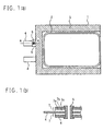
- Fig. 1 is a plane view (a) showing a battery according to the first embodiment of the present invention and a partial cross sectional view (b);
- Fig. 2 is a cross sectional view showing a construction of a battery;
- Fig. 3 is a plane view showing testing conditions of the battery according to the first embodiment of the present invention;
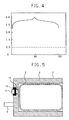
- Fig. 4 is the result of voltage variance measurement of the battery according to the first embodiment of the present invention;
- Fig. 5 is a plane view showing a battery according to the second embodiment of the present invention;
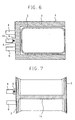
- Fig. 6 is a plane view showing a battery according to the third embodiment of the present invention;
- Fig. 7 is a plane view showing a battery according to the fourth embodiment of the present invention; and
- Fig. 8 is a plane view showing a battery according to the fifth embodiment of the present invention.
- Fig. 1 is a view showing the first embodiment of the battery in the present invention, wherein (a) is a plane view and (b) is a cross sectional view taken on line A-A in (a).
- numeral 1 indicates a battery case made of aluminum laminated sheet. It comprises a storing part 2 for a battery body formed into so-called buttercup shape, a sealing part 3 whose three peripherals are sealed by thermal melting after battery storage in order to form a hermetic construction, an extended part 6 which is extended from the sealing part 3 as a part of the battery case 1, wherein the extended part 6 is formed at the position where the part is overlapped with the positive electrode lead described below.
- Numeral 4 indicates a positive electrode lead electrically connected to the positive electrode of the battery body.
- Numeral 5 indicates a connecting means comprising a conductive material piercing the extended part 6 and the positive electrode lead 4.
- Numeral 7a indicates an aluminum foil of an aluminum laminated sheet 7.
- Numeral 7b indicates an outer sheet of the aluminum laminated sheet 7a.
- Numeral 7c is an inner sheet of the aluminum laminated sheet 7a. The conductive material 5 is plugged and the aluminum foil 7a on the extended part 6 is electrically connected to the positive electrode lead 4 through the conductive material 5.
- Fig. 1 what is made of hollow metal is shown as the conductive material 5, but it may be solid.
- the aluminum foil 7a on the extended part 6 may be electrically connected to the positive electrode lead 4, and various forms may be applied such as the one which is filled with a conductive resin in the conductive material 5 and cured.
- the aluminum laminated sheet 7 is formed by laminating a PET (poly(ethylene terephthalate)) sheet as the outer sheet 7b of the aluminum foil 7a, and the PE (polyethylene) layer as the inner sheet 7c. Thickness of the aluminum foil 7a is 20 ⁇ m, thickness of the inner sheet 7c is 90 ⁇ m, and thickness of the outer sheet 7b is 12 ⁇ m.
- Fig. 2 is a cross sectional view showing construction of a battery body, in which numeral 8 is a positive electrode, numeral 9 is an electrolytic layer such as a separator containing an electrolytic solution, numeral 10 is a negative electrode, numeral 11 is a positive electrode current collector, numeral 12 is a positive electrode active material, numeral 13 is a negative electrode active material, and 14 is a negative electrode current collector.
- the battery case shown in Fig. 1 stores the thus constructed battery body or lamination of a plurality of the battery body to prepare a battery.
- the extended part 6 which is to be plugged with the positive electrode lead through the conductive material 5 extends outside further than the thermally-melted sealing part 3. Width and length of extension are sufficient, if they are as much as the diameter of the conductive material 5. If they are less than the diameter of the conductive material 5, it is possible to connect to the positive electrode lead 4, but it decrease the possibility that the metal foil in the laminated sheet is in contact with the conductive material 5.
- the aimed shielding effect for the battery case 1 can be obtained even in case that extension is 0, i.e. the sealing part 3 is driven into the conductive material 5.
- the diameter of the conductive material 5 is preferably shorter than the width of the lead 4. This is because the conductive material 5 having a longer diameter than the lead width possibly breaks the lead 4.
- the conductive material 5 having diameter of 1.2 mm was used to the lead 4 having width of 3 mm.
- the through hole, through which the conductive material 5 goes, may be pierced on the lead 4 and the extended part 6 previously or simultaneously by means of driving-in of the conductive material 5. If it is previously pierced, hole diameter is preferably the same as or shorter than the diameter of the conductive material 5. When a through hole larger than the diameter of the conductive material 5 is pierced, it may decrease the possibility that the conductive material 5 is in contact with the lead 4 and metal foil on the extended part 6.
- the plug position of the lead 4 and the extended part 6 with the conductive material 5 may be anywhere, as long as the conductive material 5 is in contact with the metal on the lead 4 and the extended part 6. It is preferably positioned on the centerline of the width of the lead 4, since the contact ratio becomes the highest.
- the extended part 6 is placed at the position where the part is overlapped with the lead 4.
- a part of the PET film is burned out by using a carbon dioxide gas laser to connect a lead wire 10 to the exposed part 9 formed by exposing the aluminum surface. Then a voltage variance was measured between the positive electrode lead 4 and the negative electrode lead 8, and between the positive electrode lead 4 and the lead wire 10.
- Fig. 4 is a view showing the measurement results. It illustrates the voltage variance between the positive electrode lead 4 and the negative electrode lead 8, and between the positive electrode lead 4 and the lead wire 10 in case of charging and discharging of a battery having a capacity of 500 mAh with constant current of 500 mA.
- the voltage variance between the positive electrode lead 4 and the negative electrode lead 8 showed normal voltage variance and the voltage between the positive electrode lead 4 and the lead wire 10 was constant at 0 V. The result indicates that the battery case has a stable electric potential.
- the positive electrode lead was connected to the aluminum foil of the battery case, but it is better to connect the negative electrode lead in case where a stainless foil is used for the laminated sheet in place of a laminated sheet of aluminum foil.
- the inner sheet of the battery case material does not have electrochemical ion conductivity, it can be connected to any lead of either electrode.
- Fig. 5 is a plane view showing the second embodiment of the battery of the present invention.
- numeral 11 indicates an exposing part wherein the surface of the aluminum foil is exposed by burning out a PET layer by using a carbon dioxide gas laser
- numeral 12 is a stainless clip.
- the positive electrode lead 4 was folded in such a way that it was overlapped with the exposing part 11, and was fixed by sandwiching with the clip 12. Burning out of the PET layer was carried out under the conditions shown in Table 1.
- a needle prove was stabbed on the surface of the battery case 1 to compare voltage between the probe and the negative electrode lead 8 with voltage between the positive electrode lead 4 and the negative electrode lead 8, and the voltages turned out to be the same. In this way, the fact that the voltage is the same indicates that the aluminum foil on the battery case 1 has the same electrical potential as that of the positive electrode.
- Kind of laser Carbon dioxide gas laser Mode Pulse mode Frequency 200 Hz Output 16 W Pulse width 16 ⁇ sec Rate 1 m/min Spot size ⁇ 250 mm
- the lead 4 or 8 was folded and electrically connected to the exposing part.
- various connecting means such as application of a conductive paste or fixation of a conductive sheet.
- Fig. 6 is a cross sectional view showing a battery of the third embodiment in the present invention.
- numeral 13 indicates an outer lead
- numeral 6 indicates an extended part extended from the sealing part 3 as a part of the battery case 1
- numeral 5 indicates a conductive material which pierces the extended part 6 and the outer lead 13, wherein the aluminum foil on the extended part 6 is electrically connected to the outer lead 13 through the plugged conductive material 5.
- the battery case 1 comprises a battery body storing part having a molded part 2 molded into a shape of so-called buttercup which stores the battery body, and a lid laminated to the battery body storing part for hermetic construction, wherein the lid is laminated on the battery body storing part to seal four corners with the sealing part 3.
- the aluminum-laminated sheet is obtained by laminating a PET (poly(ethylene terephthalate)) sheet on the exterior of the aluminum foil and the CCP (non-drawn polypropylene) on the interior thereof. Thickness of the aluminum foil is 100 ⁇ m, and thickness of the CCP layer is 40 ⁇ m, and thickness of the PET layer is 12 ⁇ m.
- the extended part 6 which is to be plugged with the outer lead 13 by using the conductive material 5 extends outside further than the sealing part 3. Width and length of extension is sufficient if they are about diameter of the conductive material 5. The connection with the lead is still possible even if they are at most the diameter of the conductive material, but the possibility of contact between the aluminum foil on the extended part 6 and the conductive material 5 tends to decrease.
- the diameter of the conductive material 5 is preferably shorter than the width of the outer lead 13. This is because the conductive material 5 having a longer diameter than the outer lead width possibly breaks the lead 13. In this embodiment, the conductive material 5 having diameter of 1.2 mm was used to the outer lead 13 having width of 3 mm.
- the through hole, through which the extended part 6 goes, may be pierced on the outer lead 13 and the extended part 6 previously or simultaneously with driving-in of the conductive material 5. If it is previously pierced, a hole diameter is preferably the same as or shorter than the diameter of the conductive material 5. When a through hole larger than the diameter of the conductive material 5 is pierced, it may decrease possibility that the conductive material 5 is in contact with the outer lead 13 and metal foil on the extended part 6.
- the plug position of the outer lead 13 and the extended part 6 through the conductive material 5 may be anywhere, if the conductive material 5 is in contact with the metal on the outer lead 13 and the extended part 6. Preferably, it may be positioned along the centerline of the width of the outer lead 13, since a contact ratio becomes the highest. As a matter of course, it is preferably to place the extended part 6 so as to overlap with the outer lead 13.
- Fig. 7 shows a battery with a battery case of so-called pillow-shape.
- the battery is prepared by jointing both edges of an aluminum-laminated sheet (joint 14) to make the aluminum-laminated sheet cylindrical, by storing the battery body inside the cylinder and by sealing the both ends of the cylinder (sealed part 3) to have hermetic construction.
- This embodiment shows a battery prepared in the same manner as in Embodiment 1 except that the shape of the battery case is pillow-like as shown in Fig. 6.
- Embodiments 2 and 3 are also applicable to the pillow-shaped battery of this embodiment.
- Fig. 8 is a battery with a battery case whose shape is so-called bottom-lid type, wherein (b) shows a plain view and (a) shows the form of the side.
- the battery is prepared by jointing both edges of an aluminum-laminated sheet (joint 14) to make the aluminum-laminated sheet cylindrical, by storing the battery body inside the cylinder and by sealing the both ends of the cylinder (sealed part 3) with attaching the bottom lid having a shape shown in Fig. 8 (a) to have hermetic construction.
- This embodiment shows a battery prepared in the same manner as in Embodiment 1 except that the shape of the battery case is bottom-lid type as shown in Fig. 8.
- Embodiments 2 and 3 are also applicable to the bottom-lid type battery of this embodiment.
- the battery of the present invention can be used as a power source for mobile phones, radio machines, personal computers and the like, which require electric shielding (electromagnetic shielding or electrostatic shielding).
Landscapes
- Chemical & Material Sciences (AREA)
- Chemical Kinetics & Catalysis (AREA)
- Electrochemistry (AREA)
- General Chemical & Material Sciences (AREA)
- Engineering & Computer Science (AREA)
- Manufacturing & Machinery (AREA)
- Sealing Battery Cases Or Jackets (AREA)
- Connection Of Batteries Or Terminals (AREA)
Abstract
Description
| Kind of laser | Carbon dioxide gas laser |
| Mode | Pulse mode |
| Frequency | 200 Hz |
| Output | 16 W |
| Pulse width | 16 µsec |
| Rate | 1 m/min |
| Spot size | 250 mm |
Claims (8)
- A battery comprising;
a battery body having a positive electrode, a negative electrode and an electrolytic layer interposed between the positive electrode and the negative electrode; a positive electrode lead electrically connected to the positive electrode; a negative electrode lead electrically connected to the negative electrode; a battery case comprising a laminated sheet obtained by laminating a polymer resin and a metal foil, in which the battery body is stored, and a hermetic construction is formed by sealing the positive and negative electrode leads; and a means for electrically connecting the metal foil on the battery case to the positive or negative electrode lead. - A battery comprising;
a battery body having a positive electrode, a negative electrode and an electrolytic layer interposed between the positive electrode and the negative electrode; a positive electrode lead electrically connected to the positive electrode; a negative electrode lead electrically connected to the negative electrode; an outer lead equipped separately from the positive and negative electrode leads; a battery case comprising a laminated sheet obtained by laminating a polymer resin and a metal foil, in which the battery body is stored, and the positive and negative electrode leads and the outer lead are sealed to form a hermetic construction; and a means for electrically connecting the metal foil of the battery case with the outer lead. - A battery according to Claim 1 or 2,
wherein the connecting means comprises a through hole which pierces through the laminated sheet forming the battery case and the lead, and the metal foil of the battery case is electrically connected to the positive electrode lead or the negative electrode lead through a conductive material in contact with a wall surface of the through hole. - A battery according to Claim 3,
wherein the connecting means is set on an extended part which is extended from the sealing part of the laminated sheet forming the battery case. - A battery according to Claim 1 or 2,
wherein the connecting means is a means that an exposing part is formed by exposing a part of the outer surface of the metal foil in the laminated sheet forming the battery case, and the exposing part and the lead are electrically connected. - A process for examining the battery, comprising comparing voltage between an exposing part and a lead with voltage between a positive electrode lead and a negative electrode lead, wherein the exposing part is formed by exposing a part of the outer surface of the metal foil in the laminated sheet forming the battery case.
- A process for examining the battery according to Claim 6, wherein the method for exposing a part of the outer surface of the metal foil is to burn out a polymer resin by means of a laser beam.
- A process for examining the battery according to Claim 6, wherein the method for exposing a part of the outer surface of the metal foil is to expose the part by pressing a needle probe thereto.
Applications Claiming Priority (1)
| Application Number | Priority Date | Filing Date | Title |
|---|---|---|---|
| PCT/JP1999/003940 WO2001008248A1 (en) | 1999-07-23 | 1999-07-23 | Cell and cell inspecting method |
Publications (2)
| Publication Number | Publication Date |
|---|---|
| EP1120846A1 true EP1120846A1 (en) | 2001-08-01 |
| EP1120846A4 EP1120846A4 (en) | 2005-03-30 |
Family
ID=14236283
Family Applications (1)
| Application Number | Title | Priority Date | Filing Date |
|---|---|---|---|
| EP99931498A Withdrawn EP1120846A4 (en) | 1999-07-23 | 1999-07-23 | CELL AND CELL INSPECTION METHOD |
Country Status (5)
| Country | Link |
|---|---|
| US (1) | US6703162B2 (en) |
| EP (1) | EP1120846A4 (en) |
| KR (1) | KR100408140B1 (en) |
| CN (1) | CN1160821C (en) |
| WO (1) | WO2001008248A1 (en) |
Cited By (4)
| Publication number | Priority date | Publication date | Assignee | Title |
|---|---|---|---|---|
| WO2010038136A1 (en) * | 2008-10-03 | 2010-04-08 | Nissan Motor Co., Ltd. | Battery cell and monitoring device for assembled battery |
| WO2012166310A1 (en) * | 2011-05-27 | 2012-12-06 | Apple Inc. | Battery cell with an integrated pouch metal foil terminal |
| EP2816362A4 (en) * | 2012-02-13 | 2015-10-21 | Automotive Energy Supply Corp | CONDUCTIVITY TESTER AND CONDUCTIVITY TEST METHOD |
| EP1475852B1 (en) * | 2003-05-05 | 2017-01-11 | Enax, Inc. | Lead outlet structure of secondary battery in sheet type |
Families Citing this family (16)
| Publication number | Priority date | Publication date | Assignee | Title |
|---|---|---|---|---|
| JP2002343681A (en) * | 2001-05-11 | 2002-11-29 | Meidensha Corp | Electric double-layer capacitor |
| US20040161664A1 (en) * | 2001-08-14 | 2004-08-19 | Mitsubishi Denki Kabushiki Kaisha (A Corporation Of Japan) | Plate shaped battery pack and portable radio terminal |
| JP4604441B2 (en) * | 2002-07-18 | 2011-01-05 | 日本電気株式会社 | Film-clad battery and manufacturing method thereof |
| KR100544119B1 (en) * | 2003-06-24 | 2006-01-23 | 삼성에스디아이 주식회사 | Pouch Type Lithium Secondary Battery |
| JP4564781B2 (en) * | 2004-05-14 | 2010-10-20 | Necエナジーデバイス株式会社 | Battery pack |
| JP5219587B2 (en) * | 2008-03-31 | 2013-06-26 | 三洋電機株式会社 | Laminated battery and battery module including the laminated battery |
| JP4858510B2 (en) | 2008-08-12 | 2012-01-18 | ソニー株式会社 | Battery pack |
| JP5375179B2 (en) * | 2008-09-30 | 2013-12-25 | 大日本印刷株式会社 | Insulation degradation site identification method |
| DE102009025579A1 (en) * | 2009-06-19 | 2010-12-23 | Li-Tec Battery Gmbh | Battery assembly and method for its preparation |
| JP2011070989A (en) * | 2009-09-28 | 2011-04-07 | Toyota Motor Corp | Connection method of voltage detection terminal, and battery |
| JP5148579B2 (en) * | 2009-09-29 | 2013-02-20 | 三菱重工業株式会社 | Secondary battery abnormality prediction system |
| JP2012028023A (en) * | 2010-07-20 | 2012-02-09 | Nissan Motor Co Ltd | Battery |
| KR101458259B1 (en) * | 2011-01-13 | 2014-11-12 | 주식회사 엘지화학 | Pouch type secondary battery and method for manufacturing the same |
| KR101487496B1 (en) * | 2012-05-10 | 2015-01-29 | 주식회사 엘지화학 | Method and apparatus for checking insulation of pouch type secondary battery |
| US9164151B2 (en) | 2013-08-07 | 2015-10-20 | Lg Chem, Ltd. | System and method for determining isolation resistances of a battery pack |
| CN106841357B (en) * | 2017-01-20 | 2019-06-28 | 中天储能科技有限公司 | A three-electrode system testing device and its testing method |
Family Cites Families (6)
| Publication number | Priority date | Publication date | Assignee | Title |
|---|---|---|---|---|
| JPS60211763A (en) * | 1984-04-05 | 1985-10-24 | Hitachi Maxell Ltd | Manufacture of thin type battery |
| JPS62131469A (en) * | 1985-12-03 | 1987-06-13 | Japan Storage Battery Co Ltd | Thin sealed lead-acid battery |
| FR2652450B1 (en) * | 1989-09-22 | 1991-11-29 | Accumulateurs Fixes | METHOD FOR MANUFACTURING A FOAM TYPE SUPPORT ELECTRODE FOR ELECTROCHEMICAL GENERATOR AND ELECTRODE OBTAINED BY THIS METHOD. |
| US5231356A (en) * | 1992-06-16 | 1993-07-27 | Robert Parker | Flexible battery tester with a variable length resistive heater |
| JP3630510B2 (en) * | 1996-10-02 | 2005-03-16 | 旭化成エレクトロニクス株式会社 | Conductive terminal and polymer sheet package battery |
| JP3767151B2 (en) * | 1997-02-26 | 2006-04-19 | ソニー株式会社 | Thin battery |
-
1999
- 1999-07-23 EP EP99931498A patent/EP1120846A4/en not_active Withdrawn
- 1999-07-23 WO PCT/JP1999/003940 patent/WO2001008248A1/en not_active Ceased
- 1999-07-23 CN CNB998112445A patent/CN1160821C/en not_active Expired - Fee Related
- 1999-07-23 KR KR10-2001-7003543A patent/KR100408140B1/en not_active Expired - Fee Related
-
2001
- 2001-03-23 US US09/814,701 patent/US6703162B2/en not_active Expired - Fee Related
Cited By (7)
| Publication number | Priority date | Publication date | Assignee | Title |
|---|---|---|---|---|
| EP1475852B1 (en) * | 2003-05-05 | 2017-01-11 | Enax, Inc. | Lead outlet structure of secondary battery in sheet type |
| WO2010038136A1 (en) * | 2008-10-03 | 2010-04-08 | Nissan Motor Co., Ltd. | Battery cell and monitoring device for assembled battery |
| RU2474026C2 (en) * | 2008-10-03 | 2013-01-27 | Ниссан Мотор Ко., Лтд. | Accumulator battery element and monitoring device for ready-assembled battery |
| US8563152B2 (en) | 2008-10-03 | 2013-10-22 | Nissan Motor Co., Ltd. | Battery cell and monitoring device for assembled battery |
| WO2012166310A1 (en) * | 2011-05-27 | 2012-12-06 | Apple Inc. | Battery cell with an integrated pouch metal foil terminal |
| US9136509B2 (en) | 2011-05-27 | 2015-09-15 | Apple Inc. | Battery cell with an integrated pouch metal foil terminal |
| EP2816362A4 (en) * | 2012-02-13 | 2015-10-21 | Automotive Energy Supply Corp | CONDUCTIVITY TESTER AND CONDUCTIVITY TEST METHOD |
Also Published As
| Publication number | Publication date |
|---|---|
| KR20010106481A (en) | 2001-11-29 |
| KR100408140B1 (en) | 2003-12-01 |
| CN1160821C (en) | 2004-08-04 |
| US20010016279A1 (en) | 2001-08-23 |
| US6703162B2 (en) | 2004-03-09 |
| WO2001008248A1 (en) | 2001-02-01 |
| CN1319262A (en) | 2001-10-24 |
| EP1120846A4 (en) | 2005-03-30 |
Similar Documents
| Publication | Publication Date | Title |
|---|---|---|
| US6703162B2 (en) | Battery and process for examining battery | |
| KR100509606B1 (en) | Jelly-roll type battery unit and winding method thereof and lithum secondary battery using the same | |
| KR100496305B1 (en) | Pouched-type lithium secondary battery and the fabrication method thereof | |
| KR100958649B1 (en) | Battery unit, a winding method thereof, and a lithium secondary battery manufactured using the same | |
| US7824794B2 (en) | Battery having simplified arrangement for insulating electrode assembly | |
| KR102863609B1 (en) | Rechargeable battery | |
| KR101675623B1 (en) | Secondary battery and manufacturing method thereof | |
| KR20040054128A (en) | Pouched-type lithium secondary battery | |
| JP2004103579A (en) | Secondary battery with cap assembly and sealing member therefor | |
| KR102909245B1 (en) | Rechargeable battery | |
| KR102885831B1 (en) | Secondary battery and manufacturing method of the same | |
| KR102704540B1 (en) | The Case For Secondary Battery And The Pouch Type Secondary Battery | |
| KR101233514B1 (en) | Secondary battery | |
| KR102277352B1 (en) | Electrode assembly and rechargeable battery including the same | |
| JP2006310313A (en) | Secondary battery and method for manufacturing secondary battery | |
| KR102907169B1 (en) | Rechargeable battery | |
| KR100467702B1 (en) | Prismatic type lithium secondary battery | |
| KR100578982B1 (en) | Secondary battery | |
| KR102844804B1 (en) | Ultrasonic welding device | |
| KR20100128679A (en) | Secondary battery having a plastic bag and a manufacturing method thereof | |
| JP7610423B2 (en) | Secondary battery | |
| US20230268626A1 (en) | Electric storage device | |
| KR20150049520A (en) | Battery cell having a combination structure with rivet | |
| CN116487674A (en) | secondary battery | |
| KR20220048230A (en) | Secondary battery and device including the same |
Legal Events
| Date | Code | Title | Description |
|---|---|---|---|
| PUAI | Public reference made under article 153(3) epc to a published international application that has entered the european phase |
Free format text: ORIGINAL CODE: 0009012 |
|
| 17P | Request for examination filed |
Effective date: 20010420 |
|
| AK | Designated contracting states |
Kind code of ref document: A1 Designated state(s): AT BE CH CY DE DK ES FI FR GB GR IE IT LI LU MC NL PT SE |
|
| RBV | Designated contracting states (corrected) |
Designated state(s): CH DE FR GB LI |
|
| A4 | Supplementary search report drawn up and despatched |
Effective date: 20050214 |
|
| RIC1 | Information provided on ipc code assigned before grant |
Ipc: 7G 01R 31/36 B Ipc: 7H 01M 2/06 B Ipc: 7H 01M 10/48 B Ipc: 7H 01M 2/02 A |
|
| RAP1 | Party data changed (applicant data changed or rights of an application transferred) |
Owner name: MITSUBISHI DENKI KABUSHIKI KAISHA |
|
| 17Q | First examination report despatched |
Effective date: 20050919 |
|
| STAA | Information on the status of an ep patent application or granted ep patent |
Free format text: STATUS: THE APPLICATION HAS BEEN WITHDRAWN |
|
| 18W | Application withdrawn |
Effective date: 20080911 |