EP1120583A1 - Orbital speed reducer - Google Patents
Orbital speed reducer Download PDFInfo
- Publication number
- EP1120583A1 EP1120583A1 EP01460005A EP01460005A EP1120583A1 EP 1120583 A1 EP1120583 A1 EP 1120583A1 EP 01460005 A EP01460005 A EP 01460005A EP 01460005 A EP01460005 A EP 01460005A EP 1120583 A1 EP1120583 A1 EP 1120583A1
- Authority
- EP
- European Patent Office
- Prior art keywords
- pinion
- crown
- shaft
- teeth
- output shaft
- Prior art date
- Legal status (The legal status is an assumption and is not a legal conclusion. Google has not performed a legal analysis and makes no representation as to the accuracy of the status listed.)
- Withdrawn
Links
Images


Classifications
-
- F—MECHANICAL ENGINEERING; LIGHTING; HEATING; WEAPONS; BLASTING
- F16—ENGINEERING ELEMENTS AND UNITS; GENERAL MEASURES FOR PRODUCING AND MAINTAINING EFFECTIVE FUNCTIONING OF MACHINES OR INSTALLATIONS; THERMAL INSULATION IN GENERAL
- F16H—GEARING
- F16H1/00—Toothed gearings for conveying rotary motion
- F16H1/28—Toothed gearings for conveying rotary motion with gears having orbital motion
- F16H1/32—Toothed gearings for conveying rotary motion with gears having orbital motion in which the central axis of the gearing lies inside the periphery of an orbital gear
-
- F—MECHANICAL ENGINEERING; LIGHTING; HEATING; WEAPONS; BLASTING
- F16—ENGINEERING ELEMENTS AND UNITS; GENERAL MEASURES FOR PRODUCING AND MAINTAINING EFFECTIVE FUNCTIONING OF MACHINES OR INSTALLATIONS; THERMAL INSULATION IN GENERAL
- F16H—GEARING
- F16H1/00—Toothed gearings for conveying rotary motion
- F16H1/28—Toothed gearings for conveying rotary motion with gears having orbital motion
- F16H2001/2881—Toothed gearings for conveying rotary motion with gears having orbital motion comprising two axially spaced central gears, i.e. ring or sun gear, engaged by at least one common orbital gear wherein one of the central gears is forming the output
Abstract
Description
L'invention concerne les mécanismes à engrenages
comportant un arbre d'entrée (7) moteur, un arbre de sortie
5 coaxial à l'arbre d'entrée (7). Cet arbre d'entrée (7)
comporte un excentrique qui fait rouler une roue orbitale
(4) dentée 4 (1) dans une couronne (3) comportant une
denture intérieure. Cette roue orbitale (4) est associée à
une deuxième couronne 4 (2) ou un deuxième pignon 4 (3)
comportant aussi une denture qui entraíne dans sa rotation
relative un pignon 5 (1) ou une roue 5 (2) dentée
associée à l'arbre de sortie (5).The invention relates to gear mechanisms.
comprising an input shaft (7) motor, an
Ce type de mécanisme est déjà décrit partiellement dans FR A 2592121, EP O 315 609 A1 et WO 9604493A1. Le dernier concerne une denture particulière obtenue par décalage important des diamètres primitifs et taillée dans la couronne afin d'améliorer les problèmes d'interférences liées à cette disposition du pignon à l'intérieur de la couronne, le second se rapporte exclusivement à une roue orbitale faisant partie intégrante de la bague extérieure d'un roulement à bille, le premier se limite exclusivement à une roue orbitale comportant des dentures dans un même plan axial. Ces trois propositions n'ont pas trouvé d'applications industrielles connues car elles ne permettent pas la réalisation d'une gamme complète et homogène comme nous pouvons le faire par les améliorations mentionnées ci-dessous.This type of mechanism is already partially described in FR A 2592121, EP O 315 609 A1 and WO 9604493A1. The last relates to a particular toothing obtained by large offset of the original diameters and cut in the crown to improve interference problems linked to this arrangement of the pinion inside the crown, the second relates exclusively to a wheel orbital integral with the outer ring of a ball bearing, the first is limited exclusively to an orbital wheel with teeth in the same plane axial. These three proposals did not find known industrial applications because they do not allow not the realization of a complete and homogeneous range like we can do this by the improvements mentioned below.
L'intérêt économique de ces mécanismes à engrenages réducteur de vitesses est de pouvoir constituer pour chaque taille, et avec une même disposition une gamme de réduction la plus large possible correspondant à un besoin et de pouvoir transmettre des moments identiques voir même supérieurs aux mécanismes existants sur le marché tout en restant réalisable avec les moyens traditionnels. Une étude approfondie montre la nécessité de disposer de pignon et de roue les plus grands possibles dans un encombrement limité afin d'avoir des efforts minimaux sur la denture et sur les roulements. Par conséquent la durée de vie sur ces derniers devient acceptable et permet à l'ensemble d'être exploitable industriellement. Ces conditions impliquent la disposition des dentures dans des plans décalés axialement pour réduire les efforts, elles peuvent être aussi décalées radialement pour permettre la réalisation d'une gamme de réduction suffisante avec une disposition identique tout en utilisant pour palier à l'usure, des roulements interchangeables de fortes dimensions. Ces roulements sont disposés de façon à s'opposer aux efforts tangentiels dus aux moments à transmettre ainsi qu'au moment de renversement lié au décalage axial. L'engrènement est réalisé avec une denture à développante de cercle. Le problème des interférences est résolu de façon très conventionnelle en limitant la hauteur de la saillie de la denture associée à un angle de pression préservant le rendement. La faible hauteur de dent en contact conduit à l'obligation de maítriser le nombre de dents en prise pour avoir des pressions de contact acceptables avec les règles de l'art, ce dernier point est réalisé par le choix de la déformée de la dent sous un effort donné associé au décalage des dents en fonction des différents intervalles entre la couronne et le pignon retenus pour la réduction, cette déformée est fonction de deux facteurs, le choix de la hauteur du pied de dent, ainsi que le choix de la largeur de la dent. Le nombre de dents en prise est limité de façon à s'assurer d'un glissement au contact compatible avec les valeurs admissibles habituellement.The economic interest of these gear mechanisms speed reducer is to be able to constitute for each size, and with the same layout a range of reduction as wide as possible corresponding to a need and ability to transmit identical moments or even superior to existing mechanisms on the market while remaining achievable with traditional means. An in-depth study shows the need to have largest possible sprocket and wheel in a limited space in order to have minimal efforts on the teeth and on the bearings. Therefore the duration of life on these becomes acceptable and allows the whole to be industrially exploitable. These conditions involve the arrangement of the teeth in planes offset axially to reduce stress, they can also be offset radially to allow achieving a sufficient reduction range with a identical layout while using to wear and tear, strong interchangeable bearings dimensions. These bearings are arranged so that oppose the tangential forces due to the moments at transmit as well as at the time of reversal related to axial offset. The meshing is carried out with a toothing involute of circle. The problem of interference is solved in a very conventional way by limiting the height of the projection of the teeth associated with a pressure angle preserving performance. The low tooth height in contact leads to the obligation to control the number of teeth engaged to have contact pressures acceptable with the rules of the art, this last point is achieved by the choice of the deformation of the tooth under a given effort associated with tooth offset as a function of different intervals between the crown and the pinion retained for reduction, this deformation is a function of two factors, the choice of the height of the tooth foot, as well than choosing the width of the tooth. The number of teeth in grip is limited to ensure slippage contact compatible with admissible values habitually.
Par convention et pour la simplification du texte suivant, les pignons décrits ci dessous seront tous avec des dentures orientées vers l'extérieur, les couronnes seront toutes avec des dentures tournées vers l'intérieur. By convention and for the simplification of the text next, the gables described below will all be with teeth facing outwards, the crowns will be all with teeth facing inwards.
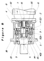
La figure représente un réducteur comportant une roue orbitale constituée d'un pignon 4 (1) et d'une couronne 4 (2) , un arbre de sortie (5) avec un pignon 5 (1), un arbre d'entrée rapide (7).The figure shows a reducer with a orbital wheel consisting of a pinion 4 (1) and a crown 4 (2), an output shaft (5) with a pinion 5 (1), a fast input shaft (7).
La figure représente un réducteur comportant une roue orbitale constituée d'un pignon 4 (1) et d'un second pignon 4 (3) , un arbre de sortie (5) avec une couronne 5 (2), un arbre d'entrée rapide (7).The figure shows a reducer with a orbital wheel consisting of a pinion 4 (1) and a second pinion 4 (3), an output shaft (5) with a crown 5 (2), a fast entry shaft (7).
La figure représente un réducteur comportant une roue orbitale constituée d'un pignon 4 (1) et d'une couronne 4 (2), un arbre de sortie (5) avec un pignon 5 (1), l'arbre d'entrée rapide (7) est entraíné par un train primaire assurant la liaison avec le moteur.The figure shows a reducer with a orbital wheel consisting of a pinion 4 (1) and a crown 4 (2), an output shaft (5) with a pinion 5 (1), the fast input shaft (7) is driven by a train primary ensuring connection with the engine.
Le mécanisme des figures A et B et C consiste en un arbre d'entrée (7) relié au moteur soit par une douille cannelée de liaison (11), soit par un train d'engrenages intermédiaire à axes parallèles ou orthogonaux comme sur la figure C et composé, d'un pignon (17) relié par clavette et porté par l'arbre (7) et façonné de manière à assurer l'équilibrage tel que la pièce (6) des figures A et B et d'un petit pignon (18) monté sur l'arbre du moteur (12). L'arbre (7) des figures A et B et C est porté par un roulement (14) monté dans l'arbre de sortie et par un roulement ou un jeux de roulements (16) montés dans le châssis fixe (2). Cet arbre (7) dit d'entrée est muni d'une partie excentrée définie par la moitié de la différence entre les pignons et couronne associés entre (3) et (4) ou entre (4) et (5). Cette partie excentrée porte des roulements de forte dimension qui font rouler le pignon 4 (1) à denture extérieure de la roue dite orbitale à l'intérieure de la couronne à denture intérieure (3) fixée au châssis (1) et (2). La roue orbitale (4) est munie selon la figure A d'une couronne 4 (2) à denture intérieure qui est maintenue au contact du pignon (5) à denture extérieure de l'arbre de sortie par l'excentrique de l'arbre (7) d'entrée, ce contact s'établit approximativement à 180° du contact entre (3) et 4 (1), la différence de nombre de dents entre 4 (2) et (5) est identique à celle entre 4 (1) et (3) (cette description de la roue orbitale (4) ayant une couronne 4 (2) est aussi applicable à la figure selon C ). Selon la figure A nous obtenons les petits et moyens rapports de réduction, la disposition de la figure C autorise des vitesses de moteurs plus rapides, et complète pour ce cas celles des figures A et B. Les figures B et C diffèrent en ce que la roue orbitale (4) est munie d'un deuxième pignon 4 (3) à denture extérieure qui est maintenue au contact de la couronne (5) à denture intérieure 5 (2) de l'arbre de sortie par l'excentrique de l'arbre (7) d'entrée, ce contact s'établit approximativement dans le même plan que le contact entre (3) et 4 (1), la différence du nombre de dents entre 4 (3) et 5 (2) est identique à celle entre 4 (1) et (3). Selon la figure B nous obtenons des rapports de réduction de valeurs moyennes à des valeurs très élevées en complément des réductions réalisables de la figure A. Ces dispositions des figures A et B réalisent donc des rapports de réduction des plus petits aux plus grands et constituent ainsi une gamme complète tout en limitant rationnellement le nombre des éléments de base pour une exploitation industrielle économique (voir l'exemple joint). L'arbre de sortie des figures A et B et C est maintenu au châssis par un roulement à quatre contacts, ou une paire de roulements à contacts obliques, ces différents montages donnent à l'ensemble une grande compacité tout en assurant une réaction directe aux efforts des liaisons de la transmission. La liaison avec l'organe entraíné est définie à la demande selon les modes habituels. Dans les figures A et B la liaison par douille cannelée permet d'assurer selon les règles de l'art la liaison avec un arbre d'entrée (7) toujours identique et des arbres moteurs différents, seul l'alésage de la douille (11) est adaptée à l'arbre moteur. De la même façon la bride porte joint (8) est adaptée à la bride du moteur et est relié au châssis (2) qui reste toujours identique.The mechanism in Figures A and B and C consists of a input shaft (7) connected to the motor either by a socket splined connection (11), either by a gear train intermediate with parallel or orthogonal axes as on the Figure C and composed of a pinion (17) connected by key and carried by the shaft (7) and shaped so as to ensure balancing such as part (6) of Figures A and B and a small pinion (18) mounted on the motor shaft (12). The tree (7) of Figures A and B and C is carried by a bearing (14) mounted in the output shaft and by a bearing or a set of bearings (16) mounted in the fixed frame (2). This input shaft (7) is provided with a eccentric part defined by half the difference between the pinions and crown associated between (3) and (4) or between (4) and (5). This eccentric part carries large bearings that roll the pinion 4 (1) with external teeth of the so-called orbital wheel with the inside of the fixed internal gear crown (3) to the chassis (1) and (2). The orbital wheel (4) is provided according to Figure A of a crown 4 (2) with internal toothing which is kept in contact with the pinion (5) with external teeth of the output shaft by the eccentric of the shaft (7) contact, this contact is established approximately 180 ° from the contact between (3) and 4 (1), the difference in number of teeth between 4 (2) and (5) is the same as between 4 (1) and (3) (this description of the orbital wheel (4) having a crown 4 (2) is also applicable to the figure according to C). According to figure A we get the small and medium reduction ratios, the arrangement of Figure C allows faster engine speeds, and full for this case those of Figures A and B. Figures B and C differ in that the orbital wheel (4) is provided with a second pinion 4 (3) with external teeth which is maintained in contact with the crown (5) with internal teeth 5 (2) of the output shaft by the eccentric of the input shaft (7), this contact is established approximately in the same plane as the contact between (3) and 4 (1), the difference in the number of teeth between 4 (3) and 5 (2) is identical to that between 4 (1) and (3). According to figure B we obtain reports of reduction of average values to very high values in complement the achievable reductions in Figure A. These provisions of Figures A and B therefore make reports reduction from the smallest to the largest and constitute thus a full range while rationally limiting the number of basic elements for an operation industrial economic (see attached example). The tree of output of Figures A and B and C is held to the chassis by a four-contact bearing, or a pair of bearings with oblique contacts, these different assemblies give the whole a great compactness while ensuring a direct reaction to the efforts of the links of the transmission. The link with the trained organ is defined on demand according to the usual modes. In figures A and B the connection by grooved sleeve allows to ensure according to the rules of the art liaison with an input tree (7) always identical and trees different motors, only the bore of the sleeve (11) is adapted to the motor shaft. In the same way the flange carries gasket (8) is adapted to the motor flange and is connected to the chassis (2) which always remains identical.
Claims (4)
Applications Claiming Priority (2)
| Application Number | Priority Date | Filing Date | Title |
|---|---|---|---|
| FR0000894 | 2000-01-25 | ||
| FR0000894A FR2804191B1 (en) | 2000-01-25 | 2000-01-25 | DEVICE FOR PRODUCING VERY COMPACT ROTARY MODULES WHICH INCLUDE A SPEED REDUCTION OF THE PLANETARY TYPE WITH ORBITAL WHEEL |
Publications (1)
| Publication Number | Publication Date |
|---|---|
| EP1120583A1 true EP1120583A1 (en) | 2001-08-01 |
Family
ID=8846260
Family Applications (1)
| Application Number | Title | Priority Date | Filing Date |
|---|---|---|---|
| EP01460005A Withdrawn EP1120583A1 (en) | 2000-01-25 | 2001-01-18 | Orbital speed reducer |
Country Status (2)
| Country | Link |
|---|---|
| EP (1) | EP1120583A1 (en) |
| FR (1) | FR2804191B1 (en) |
Cited By (4)
| Publication number | Priority date | Publication date | Assignee | Title |
|---|---|---|---|---|
| WO2007015076A3 (en) * | 2005-07-30 | 2007-05-03 | Richard Chadwick | Rotary transmission |
| EP2270360A1 (en) * | 2009-06-30 | 2011-01-05 | CAEB International S.r.l. | Improved reduction gearbox |
| FR3001518A1 (en) * | 2013-01-31 | 2014-08-01 | Claude Paul BARANGER | REDUCER WITH ORBITAL WHEEL |
| EP2960546A1 (en) * | 2014-06-27 | 2015-12-30 | Robotyka.com | Eccentric gearbox |
Citations (5)
| Publication number | Priority date | Publication date | Assignee | Title |
|---|---|---|---|---|
| FR2116760A5 (en) * | 1970-12-07 | 1972-07-21 | Thomson Csf | |
| FR2592121A1 (en) | 1985-12-23 | 1987-06-26 | Coop Goizper S | Improvements made to speed reducers |
| EP0315609A1 (en) | 1987-11-06 | 1989-05-10 | SKF Nova AB | Gear mechanism |
| EP0593036A1 (en) * | 1992-10-15 | 1994-04-20 | Sumitomo Heavy Industries, Ltd. | Gear reducer for reciprocal rotation |
| WO1996004493A1 (en) | 1994-07-29 | 1996-02-15 | Ikona Inc. | Gear system |
-
2000
- 2000-01-25 FR FR0000894A patent/FR2804191B1/en not_active Expired - Fee Related
-
2001
- 2001-01-18 EP EP01460005A patent/EP1120583A1/en not_active Withdrawn
Patent Citations (5)
| Publication number | Priority date | Publication date | Assignee | Title |
|---|---|---|---|---|
| FR2116760A5 (en) * | 1970-12-07 | 1972-07-21 | Thomson Csf | |
| FR2592121A1 (en) | 1985-12-23 | 1987-06-26 | Coop Goizper S | Improvements made to speed reducers |
| EP0315609A1 (en) | 1987-11-06 | 1989-05-10 | SKF Nova AB | Gear mechanism |
| EP0593036A1 (en) * | 1992-10-15 | 1994-04-20 | Sumitomo Heavy Industries, Ltd. | Gear reducer for reciprocal rotation |
| WO1996004493A1 (en) | 1994-07-29 | 1996-02-15 | Ikona Inc. | Gear system |
Cited By (5)
| Publication number | Priority date | Publication date | Assignee | Title |
|---|---|---|---|---|
| WO2007015076A3 (en) * | 2005-07-30 | 2007-05-03 | Richard Chadwick | Rotary transmission |
| EP2270360A1 (en) * | 2009-06-30 | 2011-01-05 | CAEB International S.r.l. | Improved reduction gearbox |
| FR3001518A1 (en) * | 2013-01-31 | 2014-08-01 | Claude Paul BARANGER | REDUCER WITH ORBITAL WHEEL |
| WO2014118446A1 (en) * | 2013-01-31 | 2014-08-07 | Claude Paul BARANGER | Device for suppressing positional deviation in a reduction gear having an orbital wheel |
| EP2960546A1 (en) * | 2014-06-27 | 2015-12-30 | Robotyka.com | Eccentric gearbox |
Also Published As
| Publication number | Publication date |
|---|---|
| FR2804191A1 (en) | 2001-07-27 |
| FR2804191B1 (en) | 2002-05-03 |
Similar Documents
| Publication | Publication Date | Title |
|---|---|---|
| EP1042135B1 (en) | Transmission device for motor vehicle with hybrid propulsion comprising a drive coupling for the electric engine | |
| EP1254329B1 (en) | Integrated assembly comprising a hydraulic clutch and a planetary gear train, in particular for automatic transmission particularly of vehicles, and automatic transmission comprising same | |
| FR2963584A1 (en) | DRIVE SYSTEM AND MOTOR VEHICLE PROVIDED WITH SUCH A DRIVE SYSTEM | |
| FR2538488A1 (en) | DRIVING UNIT FOR A MOTOR VEHICLE, COMPRISING A GEOMETRIC MAIN AXLE FOR THE MAIN ENGINE SHAFT AND A PARALLEL MAIN AXLE FOR THE OUTPUT SHAFT OF A PLANETARY GEAR TYPE GEARBOX | |
| FR2504867A1 (en) | DRIVE SYSTEM FOR A FOUR-WHEELED VEHICLE | |
| EP1875104A2 (en) | Power transmission device for a motor vehicle which is equipped with a free wheel mechanism that drives an oil pump | |
| EP1735544A1 (en) | Motor vehicle gearbox, in particular a twin-clutch gearbox | |
| FR2542835A1 (en) | PLANETARY AXIAL TYPE TORQUE CONVERTER | |
| FR2481399A1 (en) | GEARBOX FOR VEHICLES | |
| CA2785407C (en) | Grinder provided with a drive device for a crown gear | |
| EP1120583A1 (en) | Orbital speed reducer | |
| CA2882816A1 (en) | Drive gearbox on a turbomachine, consisting of a drive train with gear lines extending into non-parallel planes | |
| EP3850243A1 (en) | Mechanical reduction gearing and associated geared motor | |
| EP2182244B1 (en) | Actuator for a home automation screen and locking installation or sun protection installation comprising such an actuator. | |
| JP2001343053A (en) | Planetary gear speed reducer | |
| FR2554064A1 (en) | Utility vehicle with auxiliary attachments | |
| FR2852651A1 (en) | Gear box for motor vehicle, has primary solid shaft and concentric primary hollow shaft holding fixed pinions, and secondary shafts holding idle pinions, where fixed pinions are engaged with respective idle pinions | |
| JPH10159914A (en) | Planetary gear reduction gear | |
| FR2721083A1 (en) | Eccentric reducer. | |
| FR2657131A1 (en) | High-performance transmission machine with gearing | |
| FR2485669A1 (en) | Cycloidal bevel gear reduction train - uses double inclined input gear enmeshing with coaxial output gear and fixed concentric, outer gear | |
| FR2650977A3 (en) | TRANSMISSION UNIT FOR MOTOR VEHICLES | |
| CH363567A (en) | Variable ratio transmission mechanism | |
| JP2003021197A (en) | Hydraulic drive reduction gears | |
| FR2613449A1 (en) | Speed reducing or multiplying device and robot equipped with this device |
Legal Events
| Date | Code | Title | Description |
|---|---|---|---|
| PUAI | Public reference made under article 153(3) epc to a published international application that has entered the european phase |
Free format text: ORIGINAL CODE: 0009012 |
|
| AK | Designated contracting states |
Kind code of ref document: A1 Designated state(s): AT BE CH CY DE DK ES FI FR GB GR IE IT LI LU MC NL PT SE TR Kind code of ref document: A1 Designated state(s): DE ES GB IT |
|
| AX | Request for extension of the european patent |
Free format text: AL;LT;LV;MK;RO;SI |
|
| 17P | Request for examination filed |
Effective date: 20020114 |
|
| AKX | Designation fees paid | ||
| REG | Reference to a national code |
Ref country code: DE Ref legal event code: 8566 |
|
| RBV | Designated contracting states (corrected) |
Designated state(s): DE ES GB IT |
|
| RBV | Designated contracting states (corrected) |
Designated state(s): DE ES GB IT |
|
| 17Q | First examination report despatched |
Effective date: 20030318 |
|
| STAA | Information on the status of an ep patent application or granted ep patent |
Free format text: STATUS: THE APPLICATION IS DEEMED TO BE WITHDRAWN |
|
| 18D | Application deemed to be withdrawn |
Effective date: 20030729 |