EP1120295B1 - Pneumatic tyre - Google Patents
Pneumatic tyre Download PDFInfo
- Publication number
- EP1120295B1 EP1120295B1 EP01300592A EP01300592A EP1120295B1 EP 1120295 B1 EP1120295 B1 EP 1120295B1 EP 01300592 A EP01300592 A EP 01300592A EP 01300592 A EP01300592 A EP 01300592A EP 1120295 B1 EP1120295 B1 EP 1120295B1
- Authority
- EP
- European Patent Office
- Prior art keywords
- axially
- grooves
- oblique
- pneumatic tyre
- tyre according
- Prior art date
- Legal status (The legal status is an assumption and is not a legal conclusion. Google has not performed a legal analysis and makes no representation as to the accuracy of the status listed.)
- Expired - Lifetime
Links
Images


Classifications
-
- B—PERFORMING OPERATIONS; TRANSPORTING
- B60—VEHICLES IN GENERAL
- B60C—VEHICLE TYRES; TYRE INFLATION; TYRE CHANGING; CONNECTING VALVES TO INFLATABLE ELASTIC BODIES IN GENERAL; DEVICES OR ARRANGEMENTS RELATED TO TYRES
- B60C11/00—Tyre tread bands; Tread patterns; Anti-skid inserts
- B60C11/01—Shape of the shoulders between tread and sidewall, e.g. rounded, stepped or cantilevered
-
- B—PERFORMING OPERATIONS; TRANSPORTING
- B60—VEHICLES IN GENERAL
- B60C—VEHICLE TYRES; TYRE INFLATION; TYRE CHANGING; CONNECTING VALVES TO INFLATABLE ELASTIC BODIES IN GENERAL; DEVICES OR ARRANGEMENTS RELATED TO TYRES
- B60C11/00—Tyre tread bands; Tread patterns; Anti-skid inserts
- B60C11/03—Tread patterns
- B60C11/13—Tread patterns characterised by the groove cross-section, e.g. for buttressing or preventing stone-trapping
- B60C11/1376—Three dimensional block surfaces departing from the enveloping tread contour
- B60C11/1384—Three dimensional block surfaces departing from the enveloping tread contour with chamfered block corners
-
- B—PERFORMING OPERATIONS; TRANSPORTING
- B60—VEHICLES IN GENERAL
- B60C—VEHICLE TYRES; TYRE INFLATION; TYRE CHANGING; CONNECTING VALVES TO INFLATABLE ELASTIC BODIES IN GENERAL; DEVICES OR ARRANGEMENTS RELATED TO TYRES
- B60C11/00—Tyre tread bands; Tread patterns; Anti-skid inserts
- B60C11/03—Tread patterns
- B60C11/0302—Tread patterns directional pattern, i.e. with main rolling direction
-
- B—PERFORMING OPERATIONS; TRANSPORTING
- B60—VEHICLES IN GENERAL
- B60C—VEHICLE TYRES; TYRE INFLATION; TYRE CHANGING; CONNECTING VALVES TO INFLATABLE ELASTIC BODIES IN GENERAL; DEVICES OR ARRANGEMENTS RELATED TO TYRES
- B60C11/00—Tyre tread bands; Tread patterns; Anti-skid inserts
- B60C11/03—Tread patterns
- B60C11/11—Tread patterns in which the raised area of the pattern consists only of isolated elements, e.g. blocks
-
- B—PERFORMING OPERATIONS; TRANSPORTING
- B60—VEHICLES IN GENERAL
- B60C—VEHICLE TYRES; TYRE INFLATION; TYRE CHANGING; CONNECTING VALVES TO INFLATABLE ELASTIC BODIES IN GENERAL; DEVICES OR ARRANGEMENTS RELATED TO TYRES
- B60C11/00—Tyre tread bands; Tread patterns; Anti-skid inserts
- B60C11/03—Tread patterns
- B60C11/12—Tread patterns characterised by the use of narrow slits or incisions, e.g. sipes
- B60C11/1259—Depth of the sipe
- B60C2011/1268—Depth of the sipe being different from sipe to sipe
-
- Y—GENERAL TAGGING OF NEW TECHNOLOGICAL DEVELOPMENTS; GENERAL TAGGING OF CROSS-SECTIONAL TECHNOLOGIES SPANNING OVER SEVERAL SECTIONS OF THE IPC; TECHNICAL SUBJECTS COVERED BY FORMER USPC CROSS-REFERENCE ART COLLECTIONS [XRACs] AND DIGESTS
- Y10—TECHNICAL SUBJECTS COVERED BY FORMER USPC
- Y10S—TECHNICAL SUBJECTS COVERED BY FORMER USPC CROSS-REFERENCE ART COLLECTIONS [XRACs] AND DIGESTS
- Y10S152/00—Resilient tires and wheels
- Y10S152/03—Slits in threads
-
- Y—GENERAL TAGGING OF NEW TECHNOLOGICAL DEVELOPMENTS; GENERAL TAGGING OF CROSS-SECTIONAL TECHNOLOGIES SPANNING OVER SEVERAL SECTIONS OF THE IPC; TECHNICAL SUBJECTS COVERED BY FORMER USPC CROSS-REFERENCE ART COLLECTIONS [XRACs] AND DIGESTS
- Y10—TECHNICAL SUBJECTS COVERED BY FORMER USPC
- Y10S—TECHNICAL SUBJECTS COVERED BY FORMER USPC CROSS-REFERENCE ART COLLECTIONS [XRACs] AND DIGESTS
- Y10S152/00—Resilient tires and wheels
- Y10S152/903—Non-directional tread pattern having non-circumferential transverse groove following smooth curved path
Definitions
- the pneumatic tyre 1 is a radial tyre of size 215/70R15 for passenger cars.
- the tread width TW is the maximum axial width of the ground contacting area under a standard condition in which the tyre is mounted on a standard rim and inflated to a standard load and then loaded with a standard load.
- the standard rim is the "standard rim” specified in JATMA, the “Measuring Rim” in ETRTO, the “Design Rim” in T & RA or the like.
- the standard pressure is the "maximum air pressure" in JATMA, the “Inflation Pressure” in ETRTO, the maximum pressure given in the "Tyre Load Limits at Various Cold Inflation Pressures" table in T & RA or the like.
- each of the oblique grooves 4 is made up of a first oblique groove 4a between the middle circumferential groove 3b and outer circumferential groove 3c, and a second oblique groove 4b between the outer circumferential groove 3c and tread edge E.
- the second oblique grooves 4b comprise grooves whose width gradually increases towards the tread edge E and grooves whose width gradually increases towards the tyre equator, and these two types of grooves are alternately disposed in the tyre circumferential direction.
- the first oblique grooves 4a comprise wide grooves and narrow grooves which are alternately disposed in the tyre circumferential direction, and both the wide and narrow grooves 4a are increased in the width towards the outer circumferential grooves 3c.
- the first oblique groove 4a in this example has a deep part 6 having substantially the same depth as the central circumferential groove 3a, and a shallow part 7 having a depth less than the central circumferential groove 3a.
- the shallow part 7 extends from the inner end 4a1 of the first oblique groove 4a for a length of from 15 to 50 %, preferably 30 to 50 % of the length of the first oblique groove 4a.
- the deep part 6 is defined as the remainder on the axially outside thereof. In the shallow part 7, the depth gradually increases from the inner end 4a1 to the deep part 6.
- the above-mentioned central regions La each form a circumferentially continuous rib 9.
- the middle regions Lb each form a circumferential row of long and narrow blocks 5 of a substantially parallelogram shape.
- the outside regions Lc each forms a circumferential row of blocks 10 of a substantially rectangular shape.
- the sizes of the block pieces 5a, 5b and 5c are gradually increased from the axially inside to the outside such that the areas As1, As2 and As3 of the top surfaces of the block pieces 5a, 5b and 5c, respectively, gradually increase axially outwards, namely, As1 ⁇ As2 ⁇ As3.
- the area As1 of the axially innermost block piece 5a is in a range of from 25 to 80 %, more preferably 30 to 50 % of the widest area As3 of the axially outermost block piece 5c.
- the above-mentioned ribs 9 can be provided with sipes S3 or cuts to adjust the rigidity.
- the arrangement and inclinations of the oblique grooves and sipes are reversed between one side of the tyre equator and the other side.
- the tread pattern is rotational symmetry. Therefore, the tread pattern is bi-directional.
- a unidirectional tread pattern can be formed.
- a variable pitching method can be adopted in arranging the oblique grooves and sipes.
- a phase shift can be provided between one side of the tyre equator and the other side.
Description
- The present invention relates to a pneumatic tyre, more particularly to a tread pattern capable of improving uneven wear resistance and ride comfort in a well-balanced manner.
- In recent years, tread patterns comprising oblique grooves inclined at relatively small angles with respect to the circumferential direction became popular as suitable for radial tyres for passenger cars, sport cars and the like.
- In such a tread pattern, blocks formed between the oblique grooves are liable to be narrow and circumferentially long. As a result, uneven wear is liable to occur, and ride comfort is liable to be poor.
- Document EP-A-0 782 936 relates to a tyre tread which is provided with a straight circumferential groove on the tyre equator and on each side of the tyre equator with a straight circumferential groove from which oblique grooves originate defining blocks therebetween which are provided with sipes each extending across the blocks from one of the adjacent oblique grooves to the other and having an inclination with respect to the circumferential direction opposite to the inclination of the oblique grooves.
- Document JP 08142608 A relates to a tyre tread having an improved heel-and-toe wear resistance comprising on each side of a tyre equator oblique grooves defining therebetween blocks in which are provided sipes having an inclination with respect to the circumferential direction opposite to the inclination of the oblique grooves.
- Document JP 10264617 A shows a tyre tread similar to the above wherein the sipes are arranged in the circumferential direction of the tyre and wherein a straight circumferential groove is disposed near the tyre shoulder on each side of the tyre equator.
- It is the object of the present invention to provide a pneumatic tyre in which water drainage is improved without sacrificing uneven wear resistance and ride comfort.
- This object is achieved by a pneumatic tyre according to
claim 1 of the present invention. - An embodiment of the present invention will now be described in detail in conjunction with the accompanying drawings in which:
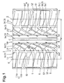
- Fig. 1 is a developed plan view of a pneumatic tyre according to the present invention showing an example of the tread pattern;
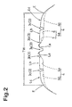
- Fig. 2 is a schematic cross sectional view of the tread portion;
- Fig. 3 is a perspective view showing blocks thereof; and
- Fig. 4 shows a tread pattern of a reference tyre used in comparison tests.
- In the drawings, a
pneumatic tyre 1 according to the present invention is provided in a tread portion 2 withcircumferential grooves 3 extending continuously in the circumferential direction of the tyre, and circumferentially spacedoblique grooves 4. - In this embodiment, the
pneumatic tyre 1 is a radial tyre of size 215/70R15 for passenger cars. - The
circumferential grooves 3 are substantially straight grooves, and include acentral groove 3a disposed on the tyre equator C, an axiallyouter groove 3c disposed on each side thereof, and amiddle groove 3b disposed between thecentral groove 3a andouter groove 3c, whereby the tread portion 2 is axially divided into two central regions La between the middlecircumferential grooves 3b and the centralcircumferential groove 3a, two middle regions Lb between the middlecircumferential grooves 3b and outercircumferential grooves 3c, and two outer regions Lc between the outercircumferential grooves 3c and tread edges E. - In order to provide greater drainage in the vicinity of the tyre equator C, the central
circumferential groove 3a is formed as the widest circumferential groove. - The widths of the central
circumferential grooves 3a and outercircumferential grooves 3c are set in a range of not less than 5 mm to provide good drainage. But, the widths of the middlecircumferential grooves 3b are set in a range of less than 5 mm to maintain tread rigidity. - The depths of the central
circumferential groove 3a and outercircumferential grooves 3c are set in a range of not less than 3 %, preferably not less than 4 % of the tread width TW (in this example about 5%). If the groove depths are less than 3% of the ground contacting width TW, it is difficult to obtain the necessary drainage. The depth of the middlecircumferential grooves 3b is set in a range of from 20 to 50 % of the depth of the centralcircumferential grooves 3a to prevent the tread rigidity from decreasing. - Here, the tread width TW is the maximum axial width of the ground contacting area under a standard condition in which the tyre is mounted on a standard rim and inflated to a standard load and then loaded with a standard load. The standard rim is the "standard rim" specified in JATMA, the "Measuring Rim" in ETRTO, the "Design Rim" in T & RA or the like. The standard pressure is the "maximum air pressure" in JATMA, the "Inflation Pressure" in ETRTO, the maximum pressure given in the "Tyre Load Limits at Various Cold Inflation Pressures" table in T & RA or the like. In case of passenger car tyres, however, 180 kPa is used as the standard pressure. The standard load is the "maximum load capacity" in JATMA, the "Load Capacity" in ETRTO, the maximum value given in the above-mentioned table in T & RA or the like.
- The
oblique grooves 4 each extend continuously from the vicinity of the tyre equator C to one of tread edges E. - In this example, each of the
oblique grooves 4 is made up of a firstoblique groove 4a between the middlecircumferential groove 3b and outercircumferential groove 3c, and a secondoblique groove 4b between the outercircumferential groove 3c and tread edge E. - The first
oblique groove 4a is inclined at an angle θ of not more than 60 degrees, preferably not more than 45 degrees with respect to the circumferential direction of the tyre. - The first
oblique groove 4a may be formed as a substantially straight groove, but in this example, it has a curved configuration such that the angle θ gradually increases from the axially inner end 4a1 at the middlecircumferential groove 3b to the axially outer end 4a2 at the outercircumferential groove 3c. And the angle θmin of the firstoblique groove 4a at the axially inner end 4a1 is set to be more than 0 degrees but not more than 30 degrees, preferably in a range of from 15 to 30 degrees. - On the other hand, in order to increase the axial rigidity of the outer region Lc to improve the steering stability, the second
oblique groove 4b is inclined at an angle θ of more than 60 degrees, preferably not less than 75 degrees, more preferably 80 to 90 degrees with respect to the circumferential direction of the tyre. In this example, with respect to the axial direction, the secondoblique groove 4b is slightly inclined reversely to the firstoblique groove 4a. - The width of each
oblique groove 4 is set in a range of not less than 2.5 %, preferably not less than 3.0 %, more preferably 3.0 to 3.5 % of the tread width TW. - In this example, the second
oblique grooves 4b comprise grooves whose width gradually increases towards the tread edge E and grooves whose width gradually increases towards the tyre equator, and these two types of grooves are alternately disposed in the tyre circumferential direction. - The first
oblique grooves 4a comprise wide grooves and narrow grooves which are alternately disposed in the tyre circumferential direction, and both the wide andnarrow grooves 4a are increased in the width towards the outercircumferential grooves 3c. - As to the depth of the
oblique groove 4, as shown in Fig. 2 and Fig. 3, the firstoblique groove 4a in this example has adeep part 6 having substantially the same depth as the centralcircumferential groove 3a, and a shallow part 7 having a depth less than the centralcircumferential groove 3a. - The shallow part 7 extends from the inner end 4a1 of the first
oblique groove 4a for a length of from 15 to 50 %, preferably 30 to 50 % of the length of the firstoblique groove 4a. Thedeep part 6 is defined as the remainder on the axially outside thereof. In the shallow part 7, the depth gradually increases from the inner end 4a1 to thedeep part 6. - The above-mentioned central regions La each form a circumferentially continuous rib 9. The middle regions Lb each form a circumferential row of long and
narrow blocks 5 of a substantially parallelogram shape. Also the outside regions Lc each forms a circumferential row ofblocks 10 of a substantially rectangular shape. - The long and
narrow blocks 5 are formed such that the ratio (B/A) of the length B of the block's oblique edge 11 along each of the adjacentoblique grooves 4 to the length A of the block'scircumferential edge 10 along the middlecircumferential groove 3b is set in a angle of not less than 1.5, preferably not less than 2.0. - A block having such a long oblique edge 11 has a tendency to be poor in resistance to uneven wear and envelope effect or ride comfort. In the present invention, therefore, each
block 5 is provided, as can be seen in Fig 4, with at least two sipes S each extending there-across from one of the adjacent firstoblique grooves 4a to the other, while inclining reversibly to the firstoblique grooves 4a. - The sipes S are defined as a cut or very narrow groove having a width of from 0.6 to 2.0 mm, preferably 0.6 to 1.5 mm, more preferably 0.6 to 1.0 mm.
- It is preferable that the sipes S are inclined at an angle of not more than 60 degrees, more preferably 30 to 45 degrees with respect to the circumferential direction of the tyre. As a result, the
block 5 is subdivided into at least three block pieces: an axiallyinnermost block piece 5a, an axiallyoutermost block piece 5c, and at least onemiddle block piece 5b therebetween. - As to the depth of the sipes, it is preferable to gradually increase the depth from the axially innermost sipe to the axially outermost sipe, that is, the axially inner sipe is shallower than the axially outer sipe. In this example, two sipes S1 and S2 are provided, and the depth D1 of the axially inner sipe S1 is less than the depth D2 of the axially outer sipe S2.
- The depth D1 of the axially innermost sipe S1 is set in a range of from 10 to 30 %, more preferably 20 to 25 % of the depth of the
deep part 6 of the firstoblique groove 4a. The depth D2 of the axially outermost sipe S2 is set in a range of from 20 to 40 %, preferably 30 to 40 % of the depth of thedeep part 6. - Further, the sizes of the
block pieces block pieces - It is preferable that the area As1 of the axially
innermost block piece 5a is in a range of from 25 to 80 %, more preferably 30 to 50 % of the widest area As3 of the axiallyoutermost block piece 5c. - The diameter of the tyre is a maximum at the tyre equator C and decreases towards the tread edges E. The rate of change or decrease is relatively small in the vicinity of the tyre equator C. Therefore, slippage on the road surface during running is smaller in the
inner block piece 5a than theouter block piece 5c. Accordingly, even when the area As1 of theinner block piece 5a is decreased, uneven wear does not concentrate on theinner block piece 5a. Especially, as the firstoblique groove 4a is provided with the shallow part 7, even when the area As1 is decreased relatively, an excessive decrease in the rigidity can be avoided, and the resultant deterioration in the steering stability is effectively prevented. - In this example, as shown in Fig. 1, the sipe S1 in a
block 5 and the sipe S2 on anext block 5 and further a sipe provided on one of the axiallyouter blocks 10 are aligned along a slightly curved line which extends axially outwards from the middle circumferential groove beyond the tread edge E across the firstoblique grooves 4a and outercircumferential groove 3c. - Further, as shown in Fig. 3, the
circumferential ends 5i, 5o of eachblock 5 formed in the corners between thecircumferential grooves oblique grooves 4a, are chamfered by a substantiallytriangular slope 13 to remove pointed ends P. Preferably, theslope 13 extends from the ground contacting top face of theblock 5 to a depth (h) of from 10 to 30 %, preferably 10 to 20 % of the maximum height H of theblock 5. Therefore, uneven wear and tearing-off of the block is prevented, and impact noise is further reduced. - The above-mentioned ribs 9 can be provided with sipes S3 or cuts to adjust the rigidity.
- In the example shown in Fig. 1, the arrangement and inclinations of the oblique grooves and sipes are reversed between one side of the tyre equator and the other side. Generally speaking, the tread pattern is rotational symmetry. Therefore, the tread pattern is bi-directional. In this invention, however, it is also possible to provide a unidirectional tread pattern. For example, by making the arrangement and inclinations of the oblique grooves and sipes on one side of the tyre equator the same as those on the other side, a unidirectional tread pattern can be formed. In any case, if necessary, a variable pitching method can be adopted in arranging the oblique grooves and sipes. Further, a phase shift can be provided between one side of the tyre equator and the other side.
- In the case of passenger car tyres, it is preferable that the
block 5 is subdivided into three pieces as explained above. But, theblock 5 may be divided into more than three, for example four or five block pieces. - Radial tyres of size 215/70R15 for passenger cars were prepared and tested for wet performance, noise performance, ride comfort, wear resistance, and steering stability.
- All the test tyres had the same structure except for the tread patterns, wherein the carcass was composed of a single ply of polyester cords arranged radially at 88 degrees with respect to the tyre equator, and the tread reinforcing belt was composed of two crossed plies of steel cords.
- Example tyres 1-8 had the tread pattern shown in Fig. 1, wherein the ratio B/A was set in a range of about 1.8 to 2.2.
-
Reference tyre 1 had the tread pattern shown in Fig. 4. - Reference tyre 2 had the tread pattern shown in Fig. 1 but without the sipes.
- A test car (2000 cc Japanese passenger car) was run on a wet asphalt road provided with a 10 mm depth 20 m long water pool along a 100 metre radius circle, and the lateral acceleration (lateral-G) was measured to obtain the average lateral G, on the front wheels, in a speed range of from 50 to 80 km/h. The test results are shown in Table 1, wherein the results are indicated by an index based on Ref.
tyre 1 being 100. The larger the index, the higher the resistance to aquaplaning.
Wheel rim size: 6 1/2 X15
Inner pressure: 180 kPa - During running the test car on a smooth asphalt road at a speed of 60 km/h, the test driver evaluated the pattern noise. The results are indicated in Table 1 by an index based on the Ref.
tyre 1 being 100. The smaller the index, the better the pattern noise. - During running the test car on dry uneven roads (asphalt road, gravel road, stone paved road), the test driver evaluated harshness, thrust up and damping. The results are indicated in Table 1 by an index based on
Reef tyre 1 being 100. The larger the index, the better the ride comfort. - During running the test car on a test course at a speed of 100 km/hr, 0.45G braking was made four times per 3 km. When the running distance reached 500 km, the difference between the maximum wear at the circumferential ends of
block 5 and the minimum wear in the circumferential central thereof was measured. In Table 1, the reciprocal of the difference is indicated by an index based on Ref.tyre 1 being 100. The larger the index, the better the wear resistance. - During running the test car on a dry asphalt road on a test course, the test driver evaluated the steering response during cornering, cornering limit, and behaviour at the cornering limits. The results are indicated in Table 1 by an index based on Ref.
tyre 1 being 100. The larger the index, the better the steering stability.Table 1 Tyre Ref.1 Ref.2 Ex.1 Ex.2 Ex.3 Ex.4 Ex.5 Ex.6 Ex.7 Ex.8 Central circum. groove Width (mm) 6.1 8.9 8.9 8.9 8.9 8.9 8.9 8.9 8.9 8.9 Depth (mm 8.4 8.4 8.4 8.4 8.4 8.4 84 8.4 8.4 8.4 Middle circum. groove Width (mm) - 3.0 3.0 3.0 3.0 3.0 3.0 3.0 3.0 3.0 Depth (mm) - 3.5 3.5 3.5 3.5 3.5 3.5 3.5 3.5 3.5 Outer circum. groove Width (mm) 8.0 6.0 6.0 6.0 6.0 6.0 6.0 6.0 6.0 6.0 Depth (mm) 8.4 8.4 8.4 8.4 8.4 8.4 8.4 8.4 8.4 8.4 First oblique groove Angle θ (degree) *1) 60-70 20-50 20-50 30-60 20-50 20-50 20-50 20-50 20-50 20-50 Width (mm) 3 2/4 2/4 2/4 2/4 2/4 2/4 2/4 2/4 2/4 Depth (mm)) 6.8 8.4 8.4 8.4 8.4 8.4 8.4 8.4 8.4 8.4 Second oblique groove Angle θ (degree) 80 80 80 80 80 80 80 80 80 60 Average width (mm) 3 4 4 4 4 4 4 4 4 4 Depth (mm) 6.8 8.4 8.4 8.4 8.4 8.4 8.4 8.4 8.4 8.4 Block Block piece area ratio (In:Mid:Out) - - 1:2.5:3 1:2.5:3 1.2:2 11:1 1:0.5:0.5 1:2.5:3 1:2.5:3 1:2.5:3 Cut-out part - - provided provided provided provided provided provided none provided Inner sipe depth (mm) - - 2 2 2 2 2 2.5 2 2 Outer sipe depth (mm) - - 3 3 3 3 3 2.5 3 3 Wet performance 100 100 110 105 105 105 105 105 104 105 Noise performance 100 105 110 107 110 110 110 110 107 107 Ride comfort 100 98 120 120 115 110 105 115 115 115 Uneven wear resistance 100 95 110 110 110 105 102 107 105 107 Steering stability 100 105 110 107 110 107 105 107 107 107 *1) The angle continuously changed from the inner end to the outer end. The angle at the inner end and the angle at the outer end are shown.
Claims (15)
- A pneumatic tyre (1) comprising a tread portion (2) provided on each side of the tyre equator (C) with two straight circumferential grooves (3b and 3c) and oblique grooves (4a) extending therebetween to define a circumferential row of narrow, circumferentially long blocks (5) therebetween,
said two straight circumferential grooves (3b and 3c) having different widths, wherein the axially inner straight circumferential groove (3b) has a width of less than 5 mm and the axially outer straight circumferential groove (3c) has a width of not less than 5 mm, said oblique grooves (4a) inclined at angles (θ) of not more than 60 degrees with respect to the circumferential direction of the tyre, said oblique grooves (4a) each having a variable width increasing towards the axially outer circumferential grooves (3c), said oblique grooves (4a) each having a variable depth to have a shallower part (7) extending from the axially inner end (4a1) of the oblique groove (4a) for a length of from 15 to 50 % of the length of the oblique groove (4a),
each said block (5) provided with at least two sipes (S1, S2) each extending across the block (5) from one of the adjacent oblique grooves (4a) to the other and having an inclination with respect to the circumferential direction opposite to the inclination of the oblique grooves (4a), to subdivide the block (5) into at least three block pieces (5, 5b, 5c),
the depths of said at least two sipes (S1, S2) are gradually increased from the axially innermost sipe (S1) to the axially outermost sipe (S2). - The pneumatic tyre according to claim 1,
characterised in that
the angle (θ) of each said oblique groove (4a) gradually increases from the axially inner end (4a1) to the axially outer end (4a2), and the minimum angle at the axially inner end (4a1) is more than 0 degrees but not more than 30 degrees. - The pneumatic tyre according to claim 1 or 2,
characterised in that
said at least three block pieces (5a, 5b, 5c) of each said block (5) include an axially innermost block piece (5a), an axially outermost block piece (5c) and at least one middle block piece (5b) therebetween, and the axially innermost block piece (5a) has the smallest top surface area (AS1). - The pneumatic tyre according to claim 3,
characterised in that
the areas (AS1, AS2, AS3) of the top surface of the block pieces are gradually increased from the axially innermost block piece (5a) to the axially outermost block piece (5c). - The pneumatic tyre according to claim 1, 2 or 3,
characterised in that
the tread portion (2) is provided between the axially inner circumferential grooves (3b) with a substantially straight rib (9). - The pneumatic tyre according to any of claims 1 to 5,
characterised in that
a central circumferential groove (3a) is disposed on the tyre equator (C). - The pneumatic tyre according to claim 6,
characterised in that
the central circumferential groove (3a) has a width of not less than 5 mm. - The pneumatic tyre according to any of claims 1 to 7,
characterised in that
each said block (5) is substantially a parallelogram shape. - The pneumatic tyre according to any of claims 1 to 8,
characterised in that
said oblique grooves (4a) include alternate wide grooves and narrow grooves. - The pneumatic tyre according to claim 9,
characterised in that
said oblique grooves (4a) have widths of not less than 2.5 % of the tread width (TW). - The pneumatic tyre according to any of claims 1 to 10,
characterised in that
in the shallower part (7) of the oblique groove (4a), the depth is gradually increased from the axially inner end (4a1) towards the axially outer end (4a2). - The pneumatic tyre according to any of claims 1 to 11,
characterised in that
the tread portion (2) is provided with second oblique grooves (4b) extending from the axially outer circumferential groove (3c) to the adjacent tread edge (E), the second oblique grooves (4b) having different widths including an axially inwardly increasing variable width and an axially outwardly increasing variable width. - The pneumatic tyre according to claim 12,
characterised in that
on each side of the tire equator (C), said oblique grooves (4a) are inclined to one circumferential direction with respect to the axial direction of the tire, but the second oblique grooves (4b) are inclined to the opposite circumferential direction thereto. - The pneumatic tyre according to any of claims 1 to 13,
characterised in that
said oblique grooves (4a) and sipes (S1, S2) form a bidirectional tread pattern. - The pneumatic tyre according to any of claims 1 to 13,
characterised in that
said oblique grooves (4a) and sipes (S1, S2) form a unidirectional tread pattern.
Applications Claiming Priority (2)
| Application Number | Priority Date | Filing Date | Title |
|---|---|---|---|
| JP2000014702 | 2000-01-24 | ||
| JP2000014702A JP3367927B2 (en) | 2000-01-24 | 2000-01-24 | Pneumatic tire |
Publications (3)
| Publication Number | Publication Date |
|---|---|
| EP1120295A2 EP1120295A2 (en) | 2001-08-01 |
| EP1120295A3 EP1120295A3 (en) | 2003-02-12 |
| EP1120295B1 true EP1120295B1 (en) | 2007-03-21 |
Family
ID=18542121
Family Applications (1)
| Application Number | Title | Priority Date | Filing Date |
|---|---|---|---|
| EP01300592A Expired - Lifetime EP1120295B1 (en) | 2000-01-24 | 2001-01-23 | Pneumatic tyre |
Country Status (6)
| Country | Link |
|---|---|
| US (1) | US6626215B2 (en) |
| EP (1) | EP1120295B1 (en) |
| JP (1) | JP3367927B2 (en) |
| KR (1) | KR100791867B1 (en) |
| CN (1) | CN100436165C (en) |
| DE (1) | DE60127327T2 (en) |
Families Citing this family (46)
| Publication number | Priority date | Publication date | Assignee | Title |
|---|---|---|---|---|
| JP3367927B2 (en) * | 2000-01-24 | 2003-01-20 | 住友ゴム工業株式会社 | Pneumatic tire |
| JP4632593B2 (en) * | 2001-08-31 | 2011-02-16 | 住友ゴム工業株式会社 | Pneumatic tire |
| JP4107385B2 (en) * | 2002-12-03 | 2008-06-25 | 横浜ゴム株式会社 | Pneumatic tire |
| JP4015573B2 (en) * | 2003-02-28 | 2007-11-28 | 住友ゴム工業株式会社 | Pneumatic tire |
| JP4202824B2 (en) * | 2003-05-28 | 2008-12-24 | 住友ゴム工業株式会社 | Pneumatic tire |
| KR101066533B1 (en) * | 2003-07-04 | 2011-09-21 | 피렐리 타이어 소시에떼 퍼 아찌오니 | Pair Of Front And Rear Pneumatic Tires For Motorcycles And Method Of Improving The Performance On Both Wet And Dry Ground Of A Motorcycle Equipped With Said Pair |
| KR20050038130A (en) * | 2003-10-21 | 2005-04-27 | 한국타이어 주식회사 | Tread pattern design of ultra high performance tire |
| KR20050038131A (en) * | 2003-10-21 | 2005-04-27 | 한국타이어 주식회사 | Tire tread pattern structure for four seasons |
| KR20050039425A (en) * | 2003-10-25 | 2005-04-29 | 한국타이어 주식회사 | Tread pattern of tire having improvement in hydroplaning performance |
| PT1768860E (en) | 2004-07-16 | 2008-10-27 | Pirelli | High-performance tyre for a motor vehicle |
| US9873290B2 (en) | 2004-07-16 | 2018-01-23 | Pirelli Tyre S.P.A. | High-performance tyre for a motor vehicle |
| JP4545565B2 (en) * | 2004-11-25 | 2010-09-15 | 東洋ゴム工業株式会社 | Pneumatic tire |
| US7188650B2 (en) * | 2004-12-28 | 2007-03-13 | The Goodyear Tire & Rubber Company | Siped tire tread with high transverse stiffness |
| DE502005011272D1 (en) * | 2005-02-25 | 2011-06-01 | Continental Reifen Deutschland | Vehicle tires with a tread pattern |
| JP5088319B2 (en) * | 2006-06-12 | 2012-12-05 | 横浜ゴム株式会社 | Pneumatic tire |
| JP4214159B2 (en) * | 2006-06-29 | 2009-01-28 | 住友ゴム工業株式会社 | Pneumatic tire |
| US7819153B2 (en) * | 2006-11-08 | 2010-10-26 | Bridgestone Americas Tire Operations, Llc | Tire including concave recesses in a circumferential tread |
| CN101588934B (en) * | 2006-12-20 | 2011-06-29 | 株式会社普利司通 | Pneumatic tire |
| JP5278127B2 (en) * | 2008-06-02 | 2013-09-04 | 横浜ゴム株式会社 | Pneumatic tire |
| JP4580437B2 (en) * | 2008-06-17 | 2010-11-10 | 住友ゴム工業株式会社 | Motorcycle tires |
| CN101607512B (en) * | 2008-06-18 | 2012-09-05 | 青岛黄海橡胶股份有限公司 | Tire tread of sedan meridian tire |
| BRPI0903293B1 (en) * | 2008-09-11 | 2020-10-13 | The Goodyear Tire & Rubber Company | tire having a tire tread |
| AU2010207199B2 (en) * | 2009-01-26 | 2012-12-13 | Bridgestone Corporation | Tire |
| JP5478284B2 (en) | 2010-01-29 | 2014-04-23 | 株式会社ブリヂストン | tire |
| USD642975S1 (en) | 2010-02-16 | 2011-08-09 | Bridgestone Americas Tire Operations, Llc | Tire tread |
| JP5177180B2 (en) * | 2010-06-18 | 2013-04-03 | 横浜ゴム株式会社 | Pneumatic tire |
| JP5185989B2 (en) * | 2010-09-02 | 2013-04-17 | 住友ゴム工業株式会社 | Pneumatic tire |
| JP5406911B2 (en) * | 2011-12-28 | 2014-02-05 | 住友ゴム工業株式会社 | Pneumatic tire |
| JP5432981B2 (en) | 2011-12-29 | 2014-03-05 | 住友ゴム工業株式会社 | Pneumatic tire |
| EP2620299B1 (en) | 2012-01-26 | 2015-06-17 | Sumitomo Rubber Industries, Ltd. | Pneumatic tire |
| JP5629283B2 (en) | 2012-03-15 | 2014-11-19 | 住友ゴム工業株式会社 | Pneumatic tire |
| CN104349914B (en) | 2012-06-19 | 2016-11-09 | 株式会社普利司通 | Tire |
| US9688105B2 (en) | 2012-11-30 | 2017-06-27 | Bridgestone Corporation | Pneumatic tire |
| JP6012442B2 (en) * | 2012-11-30 | 2016-10-25 | 株式会社ブリヂストン | Pneumatic tire |
| KR101419613B1 (en) * | 2012-12-26 | 2014-07-14 | 한국타이어 주식회사 | Pneumatic tire with improved tread block |
| JP6002032B2 (en) * | 2012-12-28 | 2016-10-05 | 株式会社ブリヂストン | tire |
| JP6211310B2 (en) * | 2013-06-05 | 2017-10-11 | 株式会社ブリヂストン | Pneumatic tire |
| JP5780318B2 (en) * | 2014-01-29 | 2015-09-16 | 横浜ゴム株式会社 | Pneumatic tire |
| JP5993403B2 (en) * | 2014-05-29 | 2016-09-14 | 住友ゴム工業株式会社 | Pneumatic tire |
| CN104228472A (en) * | 2014-10-08 | 2014-12-24 | 安徽佳通乘用子午线轮胎有限公司 | Ultra-high performance all-season passenger car tire |
| FR3030371A1 (en) * | 2014-12-23 | 2016-06-24 | Michelin & Cie | WINTER TIRE TREAD FOR HEAVY DUTY WINTER TIRE |
| JP6414245B2 (en) * | 2017-02-14 | 2018-10-31 | 横浜ゴム株式会社 | Pneumatic tire |
| JP6931190B2 (en) * | 2017-03-24 | 2021-09-01 | 住友ゴム工業株式会社 | tire |
| EP3378678B1 (en) * | 2017-03-24 | 2021-01-20 | Sumitomo Rubber Industries, Ltd. | Tire |
| JP7298369B2 (en) * | 2019-07-30 | 2023-06-27 | 住友ゴム工業株式会社 | tire |
| JP2022191002A (en) | 2021-06-15 | 2022-12-27 | 住友ゴム工業株式会社 | tire |
Family Cites Families (18)
| Publication number | Priority date | Publication date | Assignee | Title |
|---|---|---|---|---|
| US2926715A (en) * | 1956-11-23 | 1960-03-01 | Us Rubber Co | Tire tread |
| DE3478675D1 (en) * | 1984-08-28 | 1989-07-20 | Goodyear Tire & Rubber | Pneumatic tires |
| JPH0241908A (en) * | 1988-08-02 | 1990-02-13 | Bridgestone Corp | Pneumatic tire |
| JP2900267B2 (en) * | 1989-03-15 | 1999-06-02 | 横浜ゴム株式会社 | Pneumatic tire |
| JP2755995B2 (en) * | 1989-06-07 | 1998-05-25 | 株式会社ブリヂストン | Pneumatic tire |
| US5198047A (en) * | 1990-11-14 | 1993-03-30 | The Goodyear Tire & Rubber Company | Winter type tire tread |
| JP3391538B2 (en) * | 1994-02-02 | 2003-03-31 | 住友ゴム工業株式会社 | studless tire |
| DE69518470T2 (en) * | 1994-06-23 | 2001-05-23 | Bridgestone Corp | tire |
| JPH08142608A (en) * | 1994-11-17 | 1996-06-04 | Bridgestone Corp | Pneumatic radial tire |
| US5824169A (en) * | 1995-01-20 | 1998-10-20 | The Goodyear Tire & Rubber Company | Pneumatic tire having improved wear properties |
| JPH092027A (en) * | 1995-06-23 | 1997-01-07 | Bridgestone Corp | Pneumatic radial tire for passenger car |
| EP0782936B1 (en) * | 1995-12-29 | 2001-07-18 | Sumitomo Rubber Industries Limited | Pneumatic tyre |
| JP2934405B2 (en) * | 1996-01-30 | 1999-08-16 | 住友ゴム工業株式会社 | Pneumatic tire |
| JP3718021B2 (en) * | 1997-02-21 | 2005-11-16 | 株式会社ブリヂストン | Pneumatic radial tire for all season passenger cars |
| JPH10264612A (en) * | 1997-03-24 | 1998-10-06 | Yokohama Rubber Co Ltd:The | Pneumatic radial tire |
| JP3822310B2 (en) * | 1997-03-26 | 2006-09-20 | 株式会社ブリヂストン | Pneumatic tire |
| EP0997323B1 (en) * | 1998-10-30 | 2006-03-22 | Sumitomo Rubber Industries Ltd. | Vehicle tyre |
| JP3367927B2 (en) * | 2000-01-24 | 2003-01-20 | 住友ゴム工業株式会社 | Pneumatic tire |
-
2000
- 2000-01-24 JP JP2000014702A patent/JP3367927B2/en not_active Expired - Fee Related
-
2001
- 2001-01-22 KR KR1020010003570A patent/KR100791867B1/en active IP Right Grant
- 2001-01-23 DE DE60127327T patent/DE60127327T2/en not_active Expired - Lifetime
- 2001-01-23 EP EP01300592A patent/EP1120295B1/en not_active Expired - Lifetime
- 2001-01-23 CN CNB01101718XA patent/CN100436165C/en not_active Expired - Fee Related
- 2001-01-24 US US09/767,958 patent/US6626215B2/en not_active Expired - Fee Related
Also Published As
| Publication number | Publication date |
|---|---|
| CN1319509A (en) | 2001-10-31 |
| JP2001206020A (en) | 2001-07-31 |
| JP3367927B2 (en) | 2003-01-20 |
| US6626215B2 (en) | 2003-09-30 |
| US20020011291A1 (en) | 2002-01-31 |
| CN100436165C (en) | 2008-11-26 |
| EP1120295A2 (en) | 2001-08-01 |
| EP1120295A3 (en) | 2003-02-12 |
| KR20010074535A (en) | 2001-08-04 |
| KR100791867B1 (en) | 2008-01-07 |
| DE60127327T2 (en) | 2007-07-05 |
| DE60127327D1 (en) | 2007-05-03 |
Similar Documents
| Publication | Publication Date | Title |
|---|---|---|
| EP1120295B1 (en) | Pneumatic tyre | |
| EP2660078B1 (en) | Pneumatic tire | |
| EP2514608B1 (en) | Pneumatic tire | |
| US7673663B2 (en) | Pneumatic tire with tread having non-linear rib | |
| EP2357094B1 (en) | Heavy duty tire | |
| US8267131B2 (en) | Studless tire | |
| US8210219B2 (en) | Pneumatic tire with tread having crown rib and middle ribs | |
| EP0508090B1 (en) | Pneumatic tire having a unique footprint | |
| EP2239153B1 (en) | Pneumatic tire | |
| EP1437237B1 (en) | Pneumatic tire | |
| US9150056B2 (en) | Pneumatic tire | |
| EP0997323B1 (en) | Vehicle tyre | |
| EP0688685B1 (en) | Pneumatic Tires | |
| US9636953B2 (en) | Pneumatic tire | |
| EP0503407B1 (en) | Pneumatic tire having laterally connected lugs | |
| EP1433623B1 (en) | Heavy duty radial tire | |
| US20200376896A1 (en) | Tire | |
| EP1106391B1 (en) | Pneumatic tyre | |
| US6102093A (en) | Pneumatic tire including long blocks and wide blocks | |
| US11845302B2 (en) | Tire | |
| EP1145873B1 (en) | Vehicle tyre | |
| EP3321103B1 (en) | Heavy duty tire | |
| EP3925796B1 (en) | Tire | |
| US20220001700A1 (en) | Pneumatic tire |
Legal Events
| Date | Code | Title | Description |
|---|---|---|---|
| PUAI | Public reference made under article 153(3) epc to a published international application that has entered the european phase |
Free format text: ORIGINAL CODE: 0009012 |
|
| AK | Designated contracting states |
Kind code of ref document: A2 Designated state(s): AT BE CH CY DE DK ES FI FR GB GR IE IT LI LU MC NL PT SE TR |
|
| AX | Request for extension of the european patent |
Free format text: AL;LT;LV;MK;RO;SI |
|
| PUAL | Search report despatched |
Free format text: ORIGINAL CODE: 0009013 |
|
| AK | Designated contracting states |
Designated state(s): AT BE CH CY DE DK ES FI FR GB GR IE IT LI LU MC NL PT SE TR |
|
| AX | Request for extension of the european patent |
Extension state: AL LT LV MK RO SI |
|
| RIC1 | Information provided on ipc code assigned before grant |
Ipc: 7B 60C 11/12 B Ipc: 7B 60C 11/11 A Ipc: 7B 60C 11/13 B Ipc: 7B 60C 11/04 B |
|
| 17P | Request for examination filed |
Effective date: 20030714 |
|
| AKX | Designation fees paid |
Designated state(s): DE FR GB |
|
| 17Q | First examination report despatched |
Effective date: 20040319 |
|
| GRAP | Despatch of communication of intention to grant a patent |
Free format text: ORIGINAL CODE: EPIDOSNIGR1 |
|
| GRAS | Grant fee paid |
Free format text: ORIGINAL CODE: EPIDOSNIGR3 |
|
| GRAA | (expected) grant |
Free format text: ORIGINAL CODE: 0009210 |
|
| AK | Designated contracting states |
Kind code of ref document: B1 Designated state(s): DE FR GB |
|
| REG | Reference to a national code |
Ref country code: GB Ref legal event code: FG4D |
|
| REF | Corresponds to: |
Ref document number: 60127327 Country of ref document: DE Date of ref document: 20070503 Kind code of ref document: P |
|
| PLBE | No opposition filed within time limit |
Free format text: ORIGINAL CODE: 0009261 |
|
| STAA | Information on the status of an ep patent application or granted ep patent |
Free format text: STATUS: NO OPPOSITION FILED WITHIN TIME LIMIT |
|
| 26N | No opposition filed |
Effective date: 20071227 |
|
| PGFP | Annual fee paid to national office [announced via postgrant information from national office to epo] |
Ref country code: DE Payment date: 20110119 Year of fee payment: 11 Ref country code: FR Payment date: 20110128 Year of fee payment: 11 |
|
| PGFP | Annual fee paid to national office [announced via postgrant information from national office to epo] |
Ref country code: GB Payment date: 20110119 Year of fee payment: 11 |
|
| GBPC | Gb: european patent ceased through non-payment of renewal fee |
Effective date: 20120123 |
|
| REG | Reference to a national code |
Ref country code: FR Ref legal event code: ST Effective date: 20120928 |
|
| PG25 | Lapsed in a contracting state [announced via postgrant information from national office to epo] |
Ref country code: GB Free format text: LAPSE BECAUSE OF NON-PAYMENT OF DUE FEES Effective date: 20120123 Ref country code: DE Free format text: LAPSE BECAUSE OF NON-PAYMENT OF DUE FEES Effective date: 20120801 |
|
| REG | Reference to a national code |
Ref country code: DE Ref legal event code: R119 Ref document number: 60127327 Country of ref document: DE Effective date: 20120801 |
|
| PG25 | Lapsed in a contracting state [announced via postgrant information from national office to epo] |
Ref country code: FR Free format text: LAPSE BECAUSE OF NON-PAYMENT OF DUE FEES Effective date: 20120131 |