JP5177180B2 - Pneumatic tire - Google Patents
Pneumatic tire Download PDFInfo
- Publication number
- JP5177180B2 JP5177180B2 JP2010139530A JP2010139530A JP5177180B2 JP 5177180 B2 JP5177180 B2 JP 5177180B2 JP 2010139530 A JP2010139530 A JP 2010139530A JP 2010139530 A JP2010139530 A JP 2010139530A JP 5177180 B2 JP5177180 B2 JP 5177180B2
- Authority
- JP
- Japan
- Prior art keywords
- tire
- groove
- land portion
- circumferential main
- center
- Prior art date
- Legal status (The legal status is an assumption and is not a legal conclusion. Google has not performed a legal analysis and makes no representation as to the accuracy of the status listed.)
- Expired - Fee Related
Links
Images


Classifications
-
- B—PERFORMING OPERATIONS; TRANSPORTING
- B60—VEHICLES IN GENERAL
- B60C—VEHICLE TYRES; TYRE INFLATION; TYRE CHANGING; CONNECTING VALVES TO INFLATABLE ELASTIC BODIES IN GENERAL; DEVICES OR ARRANGEMENTS RELATED TO TYRES
- B60C11/00—Tyre tread bands; Tread patterns; Anti-skid inserts
- B60C11/03—Tread patterns
- B60C11/0304—Asymmetric patterns
-
- B—PERFORMING OPERATIONS; TRANSPORTING
- B60—VEHICLES IN GENERAL
- B60C—VEHICLE TYRES; TYRE INFLATION; TYRE CHANGING; CONNECTING VALVES TO INFLATABLE ELASTIC BODIES IN GENERAL; DEVICES OR ARRANGEMENTS RELATED TO TYRES
- B60C11/00—Tyre tread bands; Tread patterns; Anti-skid inserts
- B60C11/03—Tread patterns
- B60C11/12—Tread patterns characterised by the use of narrow slits or incisions, e.g. sipes
-
- B—PERFORMING OPERATIONS; TRANSPORTING
- B60—VEHICLES IN GENERAL
- B60C—VEHICLE TYRES; TYRE INFLATION; TYRE CHANGING; CONNECTING VALVES TO INFLATABLE ELASTIC BODIES IN GENERAL; DEVICES OR ARRANGEMENTS RELATED TO TYRES
- B60C11/00—Tyre tread bands; Tread patterns; Anti-skid inserts
- B60C11/03—Tread patterns
- B60C2011/0337—Tread patterns characterised by particular design features of the pattern
- B60C2011/0339—Grooves
- B60C2011/0358—Lateral grooves, i.e. having an angle of 45 to 90 degees to the equatorial plane
- B60C2011/0365—Lateral grooves, i.e. having an angle of 45 to 90 degees to the equatorial plane characterised by width
-
- B—PERFORMING OPERATIONS; TRANSPORTING
- B60—VEHICLES IN GENERAL
- B60C—VEHICLE TYRES; TYRE INFLATION; TYRE CHANGING; CONNECTING VALVES TO INFLATABLE ELASTIC BODIES IN GENERAL; DEVICES OR ARRANGEMENTS RELATED TO TYRES
- B60C11/00—Tyre tread bands; Tread patterns; Anti-skid inserts
- B60C11/03—Tread patterns
- B60C2011/0337—Tread patterns characterised by particular design features of the pattern
- B60C2011/0339—Grooves
- B60C2011/0358—Lateral grooves, i.e. having an angle of 45 to 90 degees to the equatorial plane
- B60C2011/0367—Lateral grooves, i.e. having an angle of 45 to 90 degees to the equatorial plane characterised by depth
- B60C2011/0369—Lateral grooves, i.e. having an angle of 45 to 90 degees to the equatorial plane characterised by depth with varying depth of the groove
-
- B—PERFORMING OPERATIONS; TRANSPORTING
- B60—VEHICLES IN GENERAL
- B60C—VEHICLE TYRES; TYRE INFLATION; TYRE CHANGING; CONNECTING VALVES TO INFLATABLE ELASTIC BODIES IN GENERAL; DEVICES OR ARRANGEMENTS RELATED TO TYRES
- B60C11/00—Tyre tread bands; Tread patterns; Anti-skid inserts
- B60C11/03—Tread patterns
- B60C2011/0337—Tread patterns characterised by particular design features of the pattern
- B60C2011/0339—Grooves
- B60C2011/0358—Lateral grooves, i.e. having an angle of 45 to 90 degees to the equatorial plane
- B60C2011/0372—Lateral grooves, i.e. having an angle of 45 to 90 degees to the equatorial plane with particular inclination angles
-
- Y—GENERAL TAGGING OF NEW TECHNOLOGICAL DEVELOPMENTS; GENERAL TAGGING OF CROSS-SECTIONAL TECHNOLOGIES SPANNING OVER SEVERAL SECTIONS OF THE IPC; TECHNICAL SUBJECTS COVERED BY FORMER USPC CROSS-REFERENCE ART COLLECTIONS [XRACs] AND DIGESTS
- Y10—TECHNICAL SUBJECTS COVERED BY FORMER USPC
- Y10S—TECHNICAL SUBJECTS COVERED BY FORMER USPC CROSS-REFERENCE ART COLLECTIONS [XRACs] AND DIGESTS
- Y10S152/00—Resilient tires and wheels
- Y10S152/03—Slits in threads
Abstract
Description
この発明は、空気入りタイヤに関し、さらに詳しくは、タイヤのドライ性能とスノー性能を両立できる空気入りタイヤに関する。 The present invention relates to a pneumatic tire, and more particularly to a pneumatic tire that can achieve both dry performance and snow performance of a tire.
近年の乗用車用の空気入りタイヤでは、タイヤのドライ性能(例えば、ドライ路面での直進走行性能、旋回性能、操縦安定性能)およびスノー性能(例えば、スノー路面でのトラクション性能)という相互に背反する性能を両立すべき要求がある。かかる課題に関する従来の空気入りタイヤには、特許文献1に記載される技術が知られている。
In recent years, pneumatic tires for passenger cars are contradictory to each other such as tire dry performance (for example, straight traveling performance on a dry road surface, turning performance, steering stability performance) and snow performance (for example, traction performance on a snow road surface). There is a requirement to balance performance. The technique described in
また、タイヤのトレッドパターンとして、タイヤ赤道線上にある陸部(センター陸部)が、タイヤの車両装着状態にて車幅方向内側にある領域(内側領域)に、相互に連通しつつタイヤ周方向に連続的に配置された円弧状の細溝を有し、また、車幅方向外側にある領域(外側領域)に、切り欠き部を有する構成が知られている。かかる構成を採用する従来の空気入りタイヤには、特許文献2に記載される技術が知られている。
In addition, as a tire tread pattern, the land portion (center land portion) on the tire equator line is in the tire circumferential direction while communicating with the region (inner region) located on the inner side in the vehicle width direction when the tire is mounted on the vehicle. There is known a configuration in which a circular arc-shaped groove continuously disposed on the outer periphery and a notch portion is provided in an area (outer area) on the outer side in the vehicle width direction. The technique described in
この発明は、タイヤのドライ性能とスノー性能を両立できる空気入りタイヤを提供することを目的とする。 It is an object of the present invention to provide a pneumatic tire that can achieve both tire dry performance and snow performance.
上記目的を達成するため、この発明にかかる空気入りタイヤは、タイヤ周方向に延在する複数の周方向主溝と、これらの周方向主溝に区画されて成る複数の陸部とを備える空気入りタイヤであって、タイヤ赤道線を境界とするトレッド部の左右の領域を内側領域および外側領域と呼ぶときに、タイヤ赤道線上に配置される前記陸部であって、内側領域に位置するセンター細溝および第一センターサイプと、外側領域に位置する切り欠き部および第二センターサイプとを有するセンター陸部を備え、前記センター細溝が円弧形状を有し、円弧形状の内径側をタイヤ接地端側に向けつつ一方の端部にて隣り合う他のセンター細溝に開口すると共に他方の端部にて内側領域側の前記周方向主溝に開口し、前記第一センターサイプが隣り合う前記センター細溝の間に配置されて前記センター細溝と内側領域側の前記周方向主溝とを結び、前記切り欠き部が一方の端部にて外側領域側の前記周方向主溝に開口すると共に他方の端部にて前記センター陸部内に終端し、前記第二センターサイプが隣り合う前記切り欠き部の間に配置されて一方の端部にて外側領域側の前記周方向主溝に接続すると共に他方の端部にて前記センター陸部内に終端し、前記センター陸部に対して内側領域側に内側セカンド陸部を備え、且つ、前記内側セカンド陸部は、前記内側セカンド陸部を横断すると共にタイヤ接地端側の前記周方向主溝に対する開口幅がタイヤ赤道線側の前記周方向主溝に対する開口幅よりも大きい内側セカンドラグ溝と、隣り合う前記内側セカンドラグ溝を繋ぐ内側セカンド細溝と、前記内側セカンド細溝とタイヤ接地端側の前記周方向主溝とを繋ぐ第一内側セカンドサイプと、前記内側セカンド細溝とタイヤ赤道線側の前記周方向主溝とを繋ぐ第二内側セカンドサイプとを備えることを特徴とする。 In order to achieve the above object, a pneumatic tire according to the present invention includes a plurality of circumferential main grooves extending in the tire circumferential direction and a plurality of land portions defined by the circumferential main grooves. When the left and right regions of the tread portion with the tire equator line as a boundary are referred to as an inner region and an outer region, the land portion is located on the tire equator line and is located in the inner region. A center land portion having a narrow groove and a first center sipe, and a notch portion and a second center sipe located in the outer region, the center narrow groove has an arc shape, and the inner diameter side of the arc shape is tire-grounded Opening in the other center narrow groove adjacent to one end while facing the end side, and opening in the circumferential main groove on the inner region side on the other end, the first center sipes are adjacent to each other. Sen -It is arranged between the narrow grooves to connect the center narrow groove and the circumferential main groove on the inner region side, and the notch portion opens to the circumferential main groove on the outer region side at one end. connected to the circumferential main groove in the outer region side with at the other terminates in the center land portion at the end portion, it is disposed between the cutout portion in which the second center sipes adjacent one end And ends in the center land portion at the other end , and has an inner second land portion on the inner region side with respect to the center land portion, and the inner second land portion crosses the inner second land portion. In addition, an inner second lug groove whose opening width with respect to the circumferential main groove on the tire ground contact end side is larger than an opening width with respect to the circumferential main groove on the tire equator line side, and an inner second thin groove that connects the adjacent inner second lug groove to each other. Groove and said inside A first inner second sipe that connects the second narrow groove and the circumferential main groove on the tire grounding end side; and a second inner second sipe that connects the inner second narrow groove and the circumferential main groove on the tire equator line side. It is characterized by providing .
この空気入りタイヤでは、車幅方向の内側領域および外側領域にセンター細溝、第一センターサイプ、切り欠き部および第二センターサイプが配置されるので、センター陸部のエッジ成分が増加して、タイヤのスノー性能(トラクション性能)が向上する。一方で、タイヤの直進性能に大きく影響する車幅方向の外側領域では、切り欠き部および第二センターサイプがセミクローズド構造を有することにより、リブ状構造が維持されて、タイヤのドライ性能(直進性能)が向上する。これにより、タイヤのドライ性能とスノー性能とが両立する利点がある。
また、この空気入りタイヤでは、内側セカンド陸部が、内側セカンドラグ溝と、内側セカンド細溝と、一対のサイプ(第一内側セカンドサイプおよび第二内側セカンドサイプ)とを備えることにより、陸部のエッジ成分が増加して、タイヤのトラクション性能が向上する。このとき、内側セカンドラグ溝では、タイヤ接地端側の周方向主溝に対する開口幅がタイヤ赤道線側の周方向主溝に対する開口幅よりも大きいので、タイヤ赤道線側におけるエッジ部の剛性が高められて、タイヤのドライ性能(直進性能)が確保される。これにより、タイヤのドライ性能とスノー性能とが両立する利点がある。
In this pneumatic tire, since the center narrow groove, the first center sipe, the notch and the second center sipe are arranged in the inner region and the outer region in the vehicle width direction, the edge component of the center land portion increases, The snow performance (traction performance) of the tire is improved. On the other hand, in the outer region in the vehicle width direction that greatly affects the straight running performance of the tire, the notch and the second center sipe have a semi-closed structure, so that the rib-like structure is maintained and the tire dry performance (straight running) Performance). Thereby, there exists an advantage which the dry performance and snow performance of a tire make compatible.
In this pneumatic tire, the inner second land portion includes an inner second lug groove, an inner second narrow groove, and a pair of sipes (a first inner second sipe and a second inner second sipe). This increases the edge component of the tire and improves the traction performance of the tire. At this time, in the inner second lug groove, since the opening width with respect to the circumferential main groove on the tire ground contact end side is larger than the opening width with respect to the circumferential main groove on the tire equator line side, the rigidity of the edge portion on the tire equator line side is increased. As a result, the dry performance (straight running performance) of the tire is ensured. Thereby, there exists an advantage which the dry performance and snow performance of a tire make compatible.
また、この発明にかかる空気入りタイヤは、前記周方向主溝に対する前記センター細溝の開口幅d1が3[mm]≦d1≦8[mm]の範囲内にあり、且つ、前記センター細溝の溝幅が前記周方向主溝に対する開口部から隣接するセンター細溝との接続部に向かうに連れて漸減する。 In the pneumatic tire according to the present invention, an opening width d1 of the center narrow groove with respect to the circumferential main groove is in a range of 3 [mm] ≦ d1 ≦ 8 [mm], and the center narrow groove The groove width gradually decreases from the opening with respect to the circumferential main groove toward the connecting portion with the adjacent center narrow groove.
この空気入りタイヤでは、センター細溝の寸法および形状が適正化されるので、タイヤのドライ性能とスノー性能とがより適正に両立できる利点がある。 In this pneumatic tire, since the size and shape of the center narrow groove are optimized, there is an advantage that both the dry performance and the snow performance of the tire can be more appropriately achieved.
また、この発明にかかる空気入りタイヤは、前記周方向主溝に対する前記切り欠き部の開口幅d2が3[mm]≦d2≦8[mm]の範囲内にある。 In the pneumatic tire according to the present invention, the opening width d2 of the notch with respect to the circumferential main groove is in the range of 3 [mm] ≦ d2 ≦ 8 [mm].
この空気入りタイヤでは、切り欠き部の寸法および形状が適正化されるので、タイヤのドライ性能とスノー性能とがより適正に両立できる利点がある。 In this pneumatic tire, since the size and shape of the notch are optimized, there is an advantage that both the dry performance and the snow performance of the tire can be achieved more appropriately.
また、この発明にかかる空気入りタイヤは、前記切り欠き部のタイヤ周方向に対する傾斜角αが50[deg]≦α≦75[deg]の範囲内にある。 In the pneumatic tire according to the present invention, the inclination angle α of the notch with respect to the tire circumferential direction is within a range of 50 [deg] ≦ α ≦ 75 [deg].
この空気入りタイヤでは、切り欠き部の傾斜角αが適正化されるので、タイヤのトラクション性能および騒音性能が確保される利点がある。 In this pneumatic tire, since the inclination angle α of the notch is optimized, there is an advantage that the traction performance and noise performance of the tire are ensured.
また、この発明にかかる空気入りタイヤは、前記内側セカンドラグ溝のタイヤ接地端側の前記周方向主溝に対する開口幅d3とタイヤ赤道線側の周方向主溝に対する開口幅d4とが1.5≦d3/d4≦2.0の関係を有する。 In the pneumatic tire according to the present invention, an opening width d3 with respect to the circumferential main groove on the tire grounding end side of the inner second lug groove and an opening width d4 with respect to the circumferential main groove on the tire equator line side are 1.5. ≦ d3 / d4 ≦ 2.0.
この空気入りタイヤでは、内側セカンドラグ溝の左右の開口幅d3、d4の比d3/d4が適正化されるので、タイヤ赤道線側(車両装着状態における車幅方向外側)のエッジ部の剛性が効果的に高められて、タイヤのドライ性能(直進性能)が確保される利点がある。 In this pneumatic tire, since the ratio d3 / d4 of the left and right opening widths d3 and d4 of the inner second lug groove is optimized, the rigidity of the edge portion on the tire equator line side (the vehicle width direction outside in the vehicle mounted state) is increased. There is an advantage that the tire is effectively enhanced and the dry performance (straight running performance) of the tire is ensured.
また、この発明にかかる空気入りタイヤは、前記内側セカンド細溝の溝幅d5が1.5[mm]≦d5≦4.0[mm]の範囲内にある。 In the pneumatic tire according to the present invention, the groove width d5 of the inner second narrow groove is in the range of 1.5 [mm] ≦ d5 ≦ 4.0 [mm].
この空気入りタイヤでは、内側セカンド細溝の溝幅d5が適正化されることにより、タイヤのドライ性能とスノー性能とが両立する利点がある。 In this pneumatic tire, there is an advantage that both the dry performance and the snow performance of the tire can be achieved by optimizing the groove width d5 of the inner second narrow groove.
また、この発明にかかる空気入りタイヤは、外側領域のショルダー部に配置される外側ショルダー陸部を備え、且つ、前記外側ショルダー陸部が、一方の端部にてタイヤ幅方向外側に開口すると共に他方の端部にて陸部内に終端する外側ショルダーラグ溝と、隣り合う前記外側ショルダーラグ溝のうち一方の前記外側ショルダーラグ溝の終端部と他方の前記外側ショルダーラグ溝の中央部とを繋ぐ外側ショルダーサイプとを有する。 The pneumatic tire according to the present invention includes an outer shoulder land portion disposed in a shoulder portion of the outer region, and the outer shoulder land portion opens outward in the tire width direction at one end portion. The outer shoulder lug groove that terminates in the land portion at the other end is connected to the terminal portion of one of the outer shoulder lug grooves adjacent to the central portion of the other outer shoulder lug groove. With outer shoulder sipes.
この空気入りタイヤでは、外側ショルダーラグ溝が非貫通構造(陸部内に終端部を有する構造)を有するので、タイヤの操縦安定性能(旋回性能)に大きく影響する外側領域側の陸部剛性が確保されて、タイヤのドライ性能が確保される。一方で、外側ショルダーサイプが隣り合う外側ショルダーラグ溝を繋ぐことにより、タイヤのトラクション性能(スノー性能)が向上する。これにより、タイヤのドライ性能とスノー性能とが両立する利点がある。 In this pneumatic tire, the outer shoulder lug groove has a non-penetrating structure (a structure having a terminal portion in the land portion), so that the land region rigidity on the outer region side that greatly affects the steering stability performance (turning performance) of the tire is ensured. Thus, the dry performance of the tire is ensured. On the other hand, the traction performance (snow performance) of the tire is improved by connecting the outer shoulder lugs adjacent to each other. Thereby, there exists an advantage which the dry performance and snow performance of a tire make compatible.
また、この発明にかかる空気入りタイヤは、前記外側ショルダー陸部がタイヤ幅方向内側のエッジ部に凹部を有する。 In the pneumatic tire according to the present invention, the outer shoulder land portion has a recess at an inner edge portion in the tire width direction.
この空気入りタイヤでは、凹部が外側ショルダー陸部の剛性を低減するので、タイヤのトラクション性能が向上する利点がある。 In this pneumatic tire, since the concave portion reduces the rigidity of the outer shoulder land portion, there is an advantage that the traction performance of the tire is improved.
また、この発明にかかる空気入りタイヤは、外側領域であって前記センター陸部に隣り合って配置される外側セカンド陸部を備え、且つ、前記外側セカンド陸部は、タイヤ周方向に対して傾斜しつつ前記外側セカンド陸部を横断すると共にタイヤ接地端側の前記周方向主溝に対する開口幅がタイヤ赤道線側の前記周方向主溝に対する開口幅よりも大きい外側セカンドラグ溝と、前記外側セカンドラグ溝に対して逆方向に傾斜しつつ前記外側セカンド陸部を横断する外側セカンドサイプとを備える。 The pneumatic tire according to the present invention includes an outer second land portion that is an outer region and is arranged adjacent to the center land portion, and the outer second land portion is inclined with respect to the tire circumferential direction. However, an outer second lug groove that traverses the outer second land portion and has an opening width with respect to the circumferential main groove on the tire ground contact end side that is larger than an opening width with respect to the circumferential main groove on the tire equator line side, and the outer second An outer second sipe that crosses the outer second land portion while being inclined in a reverse direction with respect to the lug groove.
この空気入りタイヤでは、外側セカンド陸部が外側セカンドラグ溝と外側セカンドサイプとを備えることにより、タイヤのトラクション性能が向上する。また、外側セカンドラグ溝と外側セカンドサイプとが逆方向に傾斜することにより、タイヤのトラクション性能がさらに向上する。一方で、外側セカンドラグ溝では、タイヤ接地端側の周方向主溝に対する開口幅がタイヤ赤道線側の周方向主溝に対する開口幅よりも大きいので、タイヤの直進性能に対する影響が大きいタイヤ接地端側におけるエッジ部の剛性が高められて、タイヤのドライ性能が確保される。これらにより、タイヤのドライ性能とスノー性能とが両立する利点がある。 In this pneumatic tire, the outer second land portion includes the outer second lug groove and the outer second sipe, so that the traction performance of the tire is improved. In addition, the traction performance of the tire is further improved by inclining the outer side second lug groove and the outer side second sipe in opposite directions. On the other hand, the outer second lug groove has a larger opening width with respect to the circumferential main groove on the tire ground contact end side than the opening width with respect to the circumferential main groove on the tire equator line side. The rigidity of the edge portion on the side is increased, and the dry performance of the tire is ensured. As a result, there is an advantage that the dry performance and the snow performance of the tire are compatible.
また、この発明にかかる空気入りタイヤは、前記外側セカンドラグ溝のタイヤ接地端側の前記周方向主溝に対する開口幅d6とタイヤ赤道線側の前記周方向主溝に対する開口幅d7とが1.5≦d6/d7≦2.0の関係を有する。 In the pneumatic tire according to the present invention, an opening width d6 with respect to the circumferential main groove on the tire grounding end side of the outer second lug groove and an opening width d7 with respect to the circumferential main groove on the tire equator line side are 1. 5 ≦ d6 / d7 ≦ 2.0.
この空気入りタイヤでは、外側セカンドラグ溝の左右の開口幅d6、d7の比d6/d7が適正化されるので、タイヤ接地端側(車両装着状態における車幅方向外側)のエッジ部の剛性が効果的に高められて、タイヤのドライ性能(操縦安定性能)が確保される利点がある。 In this pneumatic tire, since the ratio d6 / d7 of the left and right opening widths d6 and d7 of the outer side second lug groove is optimized, the rigidity of the edge portion on the tire ground contact end side (the vehicle width direction outer side in the vehicle mounted state) is increased. There is an advantage that the tire is effectively enhanced and the dry performance (steering stability performance) of the tire is ensured.
また、この発明にかかる空気入りタイヤは、前記外側セカンドラグ溝のタイヤ周方向に対する傾斜角βが55[deg]≦β≦75[deg]の範囲内にある。 In the pneumatic tire according to the present invention, the inclination angle β of the outer second lug groove with respect to the tire circumferential direction is in the range of 55 [deg] ≦ β ≦ 75 [deg].
この空気入りタイヤでは、外側セカンドラグ溝の傾斜角βが適正化されるので、タイヤのトラクション性能および騒音性能が確保される利点がある。 In this pneumatic tire, since the inclination angle β of the outer second lug groove is optimized, there is an advantage that the traction performance and noise performance of the tire are ensured.
また、この発明にかかる空気入りタイヤは、内側領域のショルダー部に配置される内側ショルダー陸部を備え、且つ、前記内側ショルダー陸部は、前記内側ショルダー陸部を横断すると共にタイヤ幅方向外側の開口幅がタイヤ幅方向内側の前記周方向主溝に対する開口幅よりも大きい内側ショルダーラグ溝と、隣り合う前記内側ショルダーラグ溝の間に配置されてタイヤ幅方向内側の前記周方向主溝に接続すると共に補助サイプとを有する。 The pneumatic tire according to the present invention includes an inner shoulder land portion disposed at a shoulder portion in an inner region, and the inner shoulder land portion traverses the inner shoulder land portion and is disposed on the outer side in the tire width direction. The inner shoulder lug groove whose opening width is larger than the opening width with respect to the circumferential main groove on the inner side in the tire width direction and the adjacent inner shoulder lug groove connected to the circumferential main groove on the inner side in the tire width direction And an auxiliary sipe.
この空気入りタイヤでは、内側ショルダー陸部が内側ショルダーラグ溝と補助サイプとを備えることにより、タイヤのトラクション性能が向上する利点がある。一方で、内側ショルダーラグ溝の左右の開口幅の関係が設定されてタイヤ幅方向内側の開口幅が狭められることにより、タイヤの騒音性能が確保される利点がある。 In the pneumatic tire, the inner shoulder land portion includes the inner shoulder lug groove and the auxiliary sipe, and thus there is an advantage that the traction performance of the tire is improved. On the other hand, the relationship between the left and right opening widths of the inner shoulder lug grooves is set and the opening width on the inner side in the tire width direction is narrowed, so that there is an advantage that the noise performance of the tire is ensured.
また、この発明にかかる空気入りタイヤは、インフレート時におけるタイヤレッド部の曲率半径Rとタイヤ外径SHとが1.5≦R/SH≦1.7の関係を有する。 In the pneumatic tire according to the present invention, the curvature radius R of the tire red portion and the tire outer diameter SH during inflation are in a relationship of 1.5 ≦ R / SH ≦ 1.7.
この空気入りタイヤでは、インフレート時におけるタイヤレッド部の曲率半径Rとタイヤ外径SHとの比R/SHが適正化されることにより、タイヤの接地形状が適正化される。これにより、タイヤ転動時における高周波パターンノイズが抑制されて、タイヤの騒音性能が向上する利点がある。 In this pneumatic tire, the contact shape of the tire is optimized by optimizing the ratio R / SH of the radius of curvature R of the tire red portion and the tire outer diameter SH during inflation. Thereby, the high frequency pattern noise at the time of tire rolling is suppressed, and there exists an advantage which the noise performance of a tire improves.
この発明にかかる空気入りタイヤでは、車幅方向の内側領域および外側領域にセンター細溝、第一センターサイプ、切り欠き部および第二センターサイプが配置されるので、センター陸部のエッジ成分が増加して、タイヤのスノー性能(トラクション性能)が向上する。一方で、タイヤの直進性能に大きく影響する車幅方向の外側領域では、切り欠き部および第二センターサイプがセミクローズド構造を有することにより、リブ状構造が維持されて、タイヤのドライ性能(直進性能)が向上する。これにより、タイヤのドライ性能とスノー性能とが両立する利点がある。 In the pneumatic tire according to the present invention, the center narrow groove, the first center sipe, the notch portion, and the second center sipe are arranged in the inner region and the outer region in the vehicle width direction, so that the edge component of the center land portion increases. Thus, the snow performance (traction performance) of the tire is improved. On the other hand, in the outer region in the vehicle width direction that greatly affects the straight running performance of the tire, the notch and the second center sipe have a semi-closed structure, so that the rib-like structure is maintained and the tire dry performance (straight running) Performance). Thereby, there exists an advantage which the dry performance and snow performance of a tire make compatible.
以下、この発明につき図面を参照しつつ詳細に説明する。なお、この実施の形態によりこの発明が限定されるものではない。また、この実施の形態の構成要素には、発明の同一性を維持しつつ置換可能かつ置換自明なものが含まれる。また、この実施の形態に記載された複数の変形例は、当業者自明の範囲内にて任意に組み合わせが可能である。 Hereinafter, the present invention will be described in detail with reference to the drawings. Note that the present invention is not limited to the embodiments. Further, the constituent elements of this embodiment include those that can be replaced while maintaining the identity of the invention and that are obvious for replacement. In addition, a plurality of modifications described in this embodiment can be arbitrarily combined within a range obvious to those skilled in the art.
[空気入りタイヤ]
図1は、この発明の実施の形態にかかる空気入りタイヤのトレッドパターンを示す平面図である。
[Pneumatic tire]
FIG. 1 is a plan view showing a tread pattern of a pneumatic tire according to an embodiment of the present invention.
この空気入りタイヤ1は、乗用車用タイヤであり、車両に対するタイヤの装着方向が指定されている。この実施の形態では、タイヤの車両装着状態にて、車幅方向内側にある領域を内側領域と呼び、車幅方向外側にある領域を外側領域と呼ぶ。なお、タイヤ装着方向の指定は、一般に、タイヤのサイドウォール部に表記される。
This
空気入りタイヤ1は、タイヤ周方向に延在する複数の周方向主溝21〜24と、これらの周方向主溝21〜24に区画されて成る複数の陸部31〜35とを備える。例えば、この実施の形態では、タイヤ赤道線CLを境界として車幅方向内側の領域に2本の周方向主溝21、22が配置され、また、車幅方向外側の領域に2本の周方向主溝23、24が配置されている。また、これらの周方向主溝21〜24により、5本のリブ状の陸部31〜35が区画されている。これらの陸部31〜35のうち、タイヤ赤道線CL上にある陸部をセンター陸部31と呼び、このセンター陸部31に隣接する陸部を内側セカンド陸部32および外側セカンド陸部33と呼び、これらのセカンド陸部32、33に隣接するタイヤ幅方向外側の陸部を内側ショルダー陸部34および外側ショルダー陸部35と呼ぶ。これにより、リブを基調としたトレッドパターンが形成されている。
The
この空気入りタイヤ1では、タイヤのドライ性能(例えば、ドライ路面での直進走行性能、旋回性能、操縦安定性能)およびスノー性能(例えば、スノー路面でのトラクション性能)という相互に背反する性能を両立するために、以下のような非対称トレッドパターンが採用されている。
In the
[センター陸部]
図2は、図1に記載した空気入りタイヤのセンター陸部を示す平面図である。
[Center land]
FIG. 2 is a plan view showing a center land portion of the pneumatic tire shown in FIG. 1.
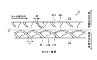
センター陸部31は、タイヤ赤道線CL上にあり、左右の周方向主溝22、23に区画されて成る。このセンター陸部31は、車幅方向の内側領域に配置されたセンター細溝311および第一センターサイプ312と、外側領域に配置された切り欠き部313および第二センターサイプ314とから成る単位パターンを有し、この単位パターンをタイヤ周方向に連続的に配置した構造を有する。
The
センター細溝311は、緩やかな円弧形状を有し、その円弧形状の内径側をタイヤ接地端側に向けて(タイヤ赤道線CL側を凸にして)配置される。また、センター細溝311は、一方の端部にて隣り合う他のセンター細溝311に開口すると共に、他方の端部にて内側領域側の周方向主溝22に開口する。また、複数のセンター細溝311が相互に連通しつつタイヤ周方向に連続的に配置される。これにより、センター陸部31の内側領域には、複数のブロック状の陸部が周方向主溝22に沿ってタイヤ周方向に配列される。かかるブロック状の陸部により、タイヤのトラクション性能(スノー性能)が向上する。
The center
なお、この実施の形態では、隣り合うセンター細溝311、311の接続部に、面取り加工が施されている。これにより、接続部におけるゴム材料の欠損が抑制されている。
In this embodiment, chamfering is applied to the connecting portions of the adjacent center
第一センターサイプ312は、隣り合うセンター細溝311、311の間に配置されて、センター細溝311と内側領域側の周方向主溝22とを繋ぐオープンサイプである。例えば、この実施の形態では、隣接する円弧形状のセンター細溝311、311により周方向主溝22に沿って陸部が扇形状のブロック部に区画され、このブロック部に第一センターサイプ312が配置されている。また、第一センターサイプ312がセンター細溝311の中央部からセンター細溝311の円弧形状の径方向(中心方向)に延在して内側領域側の周方向主溝22に至ることにより、このブロック部がさらに扇形状に二分割されている。また、第一センターサイプ312とセンター細溝311とが、タイヤ周方向に対して相互に異なる方向(ハの字状)に傾斜しつつ周方向主溝22に開口する。これらにより、タイヤのトラクション性能(スノー性能)が高められている。
The
なお、この実施の形態では、第一センターサイプ312がS字形状を有している。したがって、第一センターサイプ312が隣り合うセンター細溝311、311に区画された陸部を分割することにより、センター陸部31のトラクション性能が高められ、その一方で、第一センターサイプ312がS字形状を有することにより、センター陸部31の剛性が確保されている。
In this embodiment, the
切り欠き部313は、タイヤ周方向に対して傾斜し、また、一方の端部にて外側領域側の周方向主溝23に開口すると共に他方の端部にてセンター陸部31の外側領域内に終端するセミクローズド構造を有する。この切り欠き部313が配置されることにより、陸部のエッジ成分が増加して、タイヤのトラクション性能(スノー性能)が向上する。一方で、切り欠き部313がセミクローズド構造を有することにより、陸部のエッジ部における剛性が確保されて、タイヤのドライ性能が確保される。
The
第二センターサイプ314は、隣り合う切り欠き部313、313の間に配置されて、一方の端部にて外側領域側の周方向主溝23に至ると共に他方の端部にてセンター陸部31の外側領域内に終端するセミクローズドサイプである。例えば、この実施の形態では、第二センターサイプ314が、外側領域側の周方向主溝23のみに接続している。かかるセミクローズド構造により、タイヤの剛性が確保されて、タイヤのドライ性能が確保されている。また、第二センターサイプ314が、タイヤ周方向に対して切り欠き部313の逆方向(ハの字状)に傾斜しつつ周方向主溝23に至っている。これにより、タイヤのトラクション性能(スノー性能)が高められている。
The
以上説明したように、この空気入りタイヤ1では、センター細溝311が、円弧形状を有し、円弧形状の内径側をタイヤ接地端側に向けつつ一方の端部にて隣り合う他のセンター細溝311に開口すると共に他方の端部にて内側領域側の周方向主溝22に開口する(図1および図2参照)。また、第一センターサイプ312が、隣り合うセンター細溝311、311の間に配置されてセンター細溝311と内側領域側の周方向主溝22とを繋ぐオープン構造を有する。また、切り欠き部313が、外側領域側の周方向主溝23に開口すると共に他方の端部にてセンター陸部31内に終端するセミクローズド構造を有する。また、第二センターサイプ314が、隣り合う切り欠き部313、313の間に配置されて一方の端部にて外側領域側の周方向主溝23に接続すると共に他方の端部にてセンター陸部31内に終端するセミクローズド構造を有する。
As described above, in the
かかる構成では、車幅方向の内側領域および外側領域にセンター細溝311、第一センターサイプ312、切り欠き部313および第二センターサイプ314が配置されるので、センター陸部31のエッジ成分が増加して、タイヤのスノー性能(トラクション性能)が向上する。一方で、タイヤの直進性能に大きく影響する車幅方向の外側領域では、切り欠き部313および第二センターサイプ314がセミクローズド構造を有することにより、リブ状構造が維持されて、タイヤのドライ性能(直進性能)が向上する。これにより、タイヤのドライ性能とスノー性能とが両立する利点がある。
In such a configuration, the center
また、かかる構成では、センター陸部31が第一センターサイプ312および第二センターサイプ314を有することにより、タイヤのトラクション性能が高められる。一方で、これらのサイプ312、314を細溝としないことにより、タイヤのドライ性能が確保され、また、タイヤの騒音性能(車外騒音性能およびパターンノイズ性能)が向上する。例えば、これらのサイプを細溝とすると、陸部の剛性が低下してタイヤの直進性能が低下し、また、タイヤ回転時にて溝による打音が顕著となり騒音が大きくなる。
Moreover, in this structure, the
また、この空気入りタイヤ1では、第一センターサイプ312がセンター細溝311の中央部からセンター細溝311の円弧形状の径方向に延在する(図1および図2参照)。かかる構成では、第一センターサイプ312とセンター細溝311とがタイヤ周方向に対して相互に異なる方向(ハの字状)に傾斜しつつ周方向主溝22に至る。これにより、タイヤのトラクション性能(スノー性能)が向上する利点がある。
In the
また、この空気入りタイヤ1では、切り欠き部313がタイヤ周方向に対して傾斜すると共に、第二センターサイプ314がタイヤ周方向に対して切り欠き部313の逆方向(ハの字状)に傾斜しつつ周方向主溝23に至る(図1および図2参照)。かかる構成では、切り欠き部とサイプが同一方向に傾斜する構成と比較して、タイヤのトラクション性能(スノー性能)が向上する利点がある。
Further, in the
また、この空気入りタイヤ1では、周方向主溝22に対するセンター細溝311の開口幅d1が3[mm]≦d1≦8[mm]の範囲内にあり、且つ、センター細溝311の溝幅が周方向主溝22に対する開口部から隣接するセンター細溝311との接続部に向かうに連れて漸減する(図2参照)。かかる構成では、センター細溝311の寸法および形状が適正化されるので、タイヤのドライ性能とスノー性能とがより適正に両立できる利点がある。例えば、d1<3[mm]となると、センター陸部の剛性が高くなりトラクション性能を確保できないため、好ましくない。また、8[mm]<d1となると、センター陸部の剛性が低下して操縦安定性能が低下するため、好ましくない。
In the
なお、この実施の形態において、溝幅(例えば、センター細溝311の開口幅d1)は、タイヤを規定リムに装着してタイヤに規定内圧および規定荷重を負荷した条件下にて測定される。 In this embodiment, the groove width (for example, the opening width d1 of the center narrow groove 311) is measured under the condition that the tire is mounted on the prescribed rim and the prescribed internal pressure and the prescribed load are applied to the tire.
ここで、規定リムとは、JATMAに規定される「適用リム」、TRAに規定される「Design Rim」、あるいはETRTOに規定される「Measuring Rim」をいう。また、規定内圧とは、JATMAに規定される「最高空気圧」、TRAに規定される「TIRE LOAD LIMITS AT VARIOUS COLD INFLATION PRESSURES」の最大値、あるいはETRTOに規定される「INFLATION PRESSURES」をいう。また、規定荷重とは、JATMAに規定される「最大負荷能力」、TRAに規定される「TIRE LOAD LIMITS AT VARIOUS COLD INFLATION PRESSURES」の最大値、あるいはETRTOに規定される「LOAD CAPACITY」をいう。ただし、乗用車用タイヤの場合には、規定内圧が空気圧180[kPa]であり、規定荷重が最大負荷能力の88[%]である。 Here, the prescribed rim refers to “applied rim” prescribed in JATMA, “Design Rim” prescribed in TRA, or “Measuring Rim” prescribed in ETRTO. The specified internal pressure means “maximum air pressure” specified by JATMA, the maximum value of “TIRE LOAD LIMITS AT VARIOUS COLD INFLATION PRESSURES” specified by TRA, or “INFLATION PRESSURES” specified by ETRTO. The specified load means “maximum load capacity” defined in JATMA, the maximum value of “TIRE LOAD LIMITS AT VARIOUS COLD INFLATION PRESSURES” defined in TRA, or “LOAD CAPACITY” defined in ETRTO. However, in the case of a tire for a passenger car, the specified internal pressure is an air pressure of 180 [kPa], and the specified load is 88 [%] of the maximum load capacity.
また、この空気入りタイヤ1では、周方向主溝23に対する切り欠き部313の開口幅d2が3[mm]≦d2≦8[mm]の範囲内にあることが好ましい(図2参照)。かかる構成では、切り欠き部313の寸法および形状が適正化されるので、タイヤのドライ性能とスノー性能とがより適正に両立できる利点がある。例えば、d2<3[mm]となると、センター陸部の剛性が高くなりトラクション性能を確保できないため、好ましくない。また、8[mm]<d2となると、センター陸部の剛性が低下して操縦安定性能が低下するため、好ましくない。
In the
また、この空気入りタイヤ1では、切り欠き部313のタイヤ周方向に対する傾斜角αが50[deg]≦α≦75[deg]の範囲内にあることが好ましい(図2参照)。かかる構成では、切り欠き部313の傾斜角αが適正化されるので、タイヤのトラクション性能および騒音性能が確保される利点がある。例えば、α<50[deg]となると、センター陸部の剛性が高くなりトラクション性能を確保できないため、好ましくない。また、75[deg]<αとなると、センター陸部の剛性が低下して操縦安定性能が低下するため、好ましくない。
In the
なお、切り欠き部313の傾斜角αは、切り欠き部313の開口部の中点と、切り欠き部313の長手方向の中点における切り欠き幅の中点とを結んだ直線を基準として測定される。
The inclination angle α of the
[内側セカンド陸部]
図3は、図1に記載した空気入りタイヤの内側セカンド陸部を示す平面図である。
[Inside second land]
FIG. 3 is a plan view showing an inner second land portion of the pneumatic tire depicted in FIG. 1.
内側セカンド陸部32は、センター陸部31に対してレッド部の内側領域側に配置される。例えば、この実施の形態では、センター陸部31と内側セカンド陸部32とが周方向主溝22を挟んで隣接している。この内側セカンド陸部32は、内側セカンドラグ溝321と、内側セカンド細溝322と、一対のサイプ(第一内側セカンドサイプ323および第二内側セカンドサイプ324)とから成る単位パターンを備え、この単位パターンをタイヤ周方向に連続的に配置した構造を有する。
The inner
内側セカンドラグ溝321は、内側セカンド陸部32をタイヤ幅方向に横断して、内側セカンド陸部32の左右の周方向主溝21、22に開口する。この内側セカンドラグ溝321では、タイヤ接地端側の周方向主溝21に対する開口幅d3がタイヤ赤道線CL側の周方向主溝22に対する開口幅d4よりも大きい(d3>d4)。例えば、この実施の形態では、内側セカンドラグ溝321が直線形状ないしは緩やかな円弧形状を有し、タイヤ幅方向に対して緩やかに傾斜して配置されている。また、内側セカンドラグ溝321が内側セカンド陸部32の中央部にて溝幅をステップ状に拡幅した形状を有している。また、広い開口幅d3を有する部分の溝深さが、狭い開口幅d4を有する部分の溝深さよりも大きく設定されることにより、陸部の左右の剛性に差が設けられている。
The inner side
内側セカンド細溝322は、隣り合う内側セカンドラグ溝321、321を繋ぐ細溝である。例えば、この実施の形態では、内側セカンド細溝322が直線形状を有し、隣り合う内側セカンドラグ溝321、321の中央部を繋いでいる。また、内側セカンド細溝322がタイヤ周方向に対して傾斜している。したがって、隣り合う内側セカンド細溝322、322が共通の内側セカンドラグ溝321に対して相互に異なる位置で開口している。
The inner second
第一内側セカンドサイプ323は、内側セカンド細溝322とタイヤ接地端側の周方向主溝21とを繋ぐオープンサイプである。例えば、この実施の形態では、第一内側セカンドサイプ323が略S字形状を有し、内側セカンド細溝322の中央部から蛇行しつつタイヤ幅方向に延在してタイヤ接地端側の周方向主溝21に接続している。また、第一内側セカンドサイプ323が内側セカンドラグ溝321に対して逆方向(ハの字状)に傾斜しつつ周方向主溝21に至っている。
The first inner
第二内側セカンドサイプ324は、内側セカンド細溝322とタイヤ赤道線CL側の周方向主溝22とを繋ぐオープンサイプである。例えば、この実施の形態では、第二内側セカンドサイプ324が略S字形状を有し、内側セカンド細溝322の中央部から蛇行しつつタイヤ幅方向に延在してタイヤ赤道線CL側の周方向主溝22に接続している。また、第二内側セカンドサイプ324が内側セカンドラグ溝321に対して逆方向(ハの字状)に傾斜しつつ周方向主溝22に至っている。
The second inner
以上説明したように、この空気入りタイヤ1では、内側セカンド陸部32は、内側セカンド陸部32を横断すると共にタイヤ接地端側の周方向主溝21に対する開口幅d3がタイヤ赤道線CL側の周方向主溝22に対する開口幅d4よりも大きい内側セカンドラグ溝321と、隣り合う内側セカンドラグ溝321、321を繋ぐ内側セカンド細溝322と、内側セカンド細溝322とタイヤ接地端側の周方向主溝21とを繋ぐ第一内側セカンドサイプ323と、内側セカンド細溝322とタイヤ赤道線CL側の周方向主溝22とを繋ぐ第二内側セカンドサイプ324とを備える(図1および図3参照)。かかる構成では、内側セカンド陸部32が、内側セカンドラグ溝321と、内側セカンド細溝322と、一対のサイプ(第一内側セカンドサイプ323および第二内側セカンドサイプ324)とを備えることにより、陸部のエッジ成分が増加して、タイヤのトラクション性能が向上する。このとき、内側セカンドラグ溝321では、タイヤ接地端側の周方向主溝21に対する開口幅d3がタイヤ赤道線CL側の周方向主溝22に対する開口幅d4よりも大きいので、タイヤ赤道線CL側におけるエッジ部の剛性が高められて、タイヤのドライ性能(直進性能)が確保される。これにより、タイヤのドライ性能とスノー性能とが両立する利点がある。
As described above, in the
また、この空気入りタイヤ1では、外側セカンド陸部33の溝面積(溝およびサイプの総面積)が内側セカンド陸部32の溝面積よりも小さく設定される(図1参照)。かかる構成では、内側セカンド陸部32および外側セカンド陸部33が溝およびサイプを有することにより、陸部のエッジ成分が増加して、タイヤのトラクション性能が高められる。一方で、外側セカンド陸部33の溝面積が内側セカンド陸部32の溝面積よりも小さく設定されることにより、タイヤの直進性能に大きく影響する外側セカンド陸部33の剛性が維持されて、タイヤのドライ性能が確保される。これにより、タイヤのドライ性能とスノー性能とが両立する利点がある。
Further, in the
特に、上記のセンター陸部31と内側セカンド陸部32とが組み合わされる構成では、センター陸部31がタイヤの直進性能を確保しつつ内側セカンド陸部32がタイヤのトラクション性能を向上させるので、タイヤのドライ性能およびスノー性能がより適正に両立する利点がある。
In particular, in the configuration in which the
また、この空気入りタイヤ1では、内側セカンドラグ溝321のタイヤ接地端側の前記周方向主溝21に対する開口幅d3とタイヤ赤道線CL側の周方向主溝22に対する開口幅d4とが1.5≦d3/d4≦2.0の関係を有することが好ましい(図3参照)。かかる構成では、内側セカンドラグ溝321の左右の開口幅d3、d4の比d3/d4が適正化されるので、タイヤ赤道線CL側(車両装着状態における車幅方向外側)のエッジ部の剛性が効果的に高められて、タイヤのドライ性能(直進性能)が確保される利点がある。
Further, in this
また、この空気入りタイヤ1では、隣り合う内側セカンド細溝322、322が共通の内側セカンドラグ溝321に対して相互に異なる位置で開口することが好ましい(図3参照)。例えば、この実施の形態では、内側セカンドラグ溝321がタイヤ幅方向に対して傾斜しつつ左右の周方向主溝21、22に開口しており、また、隣り合う内側セカンド細溝322、322がこの内側セカンドラグ溝321にそれぞれ開口している。このとき、隣り合う内側セカンド細溝322、322がタイヤ周方向に対して傾斜することにより、この内側セカンドラグ溝321に対して相互に異なる位置で開口している。かかる構成では、内側セカンド陸部32が内側セカンドラグ溝321および内側セカンド細溝322に分割されて、タイヤ周方向にジグザグ状に配列されたブロック状の陸部が形成される。すると、タイヤ転動時にて、これらの分割部が順次接地することにより独立して変形できるので、内側セカンド陸部32のトラクション性能が向上する。これにより、タイヤのスノー性能が向上する利点がある。
Moreover, in this
また、この空気入りタイヤ1では、内側セカンドラグ溝321がタイヤ幅方向に対して傾斜すると共に、第一内側セカンドサイプ323あるいは第二内側セカンドサイプ324が内側セカンドラグ溝321に対して逆方向(ハの字状)に傾斜しつつ周方向主溝21、22に至ることが好ましい(図3参照)。例えば、この実施の形態では、内側セカンドラグ溝321がタイヤ幅方向に対して傾斜しつつ左右の周方向主溝21、22に開口しており、また、第一内側セカンドサイプ323および第二内側セカンドサイプ324がS字状に蛇行しつつ内側セカンドラグ溝321に対して逆方向に傾斜して対応する周方向主溝21、22にそれぞれ開口している。かかる構成では、ラグ溝とサイプが同一方向に傾斜する構成と比較して、タイヤのトラクション性能(スノー性能)が向上する利点がある。
In the
また、この空気入りタイヤ1では、内側セカンド細溝322の溝幅d5が1.5[mm]≦d5≦4.0[mm]の範囲内にあることが好ましい(図3参照)。かかる構成では、内側セカンド細溝322の溝幅d5が適正化されることにより、タイヤのドライ性能とスノー性能とが両立する利点がある。例えば、d5<1.5[mm]となると、内側セカンド細溝322の排雪性が悪化してタイヤのスノー性能が低下し、4.0[mm]<d5となると、内側セカンド陸部32のブロック剛性が低下して、タイヤのドライ性能(操縦安定性能)が低下するため、好ましくない。
Moreover, in this
[外側ショルダー陸部]
図4は、図1に記載した空気入りタイヤの外側ショルダー陸部を示す平面図である。
[Outer shoulder land]
FIG. 4 is a plan view showing an outer shoulder land portion of the pneumatic tire depicted in FIG. 1.
外側ショルダー陸部35は、トレッド部の外側領域のショルダー部に配置される(図1および図4参照)。例えば、この実施の形態では、外側ショルダー陸部35が外側領域のショルダー部であって外側セカンド陸部33のタイヤ幅方向外側に周方向主溝24を隔てて配置されている。この外側ショルダー陸部35は、外側ショルダーラグ溝351と、外側ショルダーサイプ352と、補助サイプ353と、凹部354とから成る単位パターンを備え、この単位パターンをタイヤ周方向に連続的に配置した構造を有する。
The outer
外側ショルダーラグ溝351は、一方の端部にてタイヤ幅方向外側に延在して開口すると共に他方の端部にて陸部内に終端するセミクローズド構造を有する。したがって、この外側ショルダーラグ溝351は、タイヤ幅方向内側の周方向主溝24に開口していない。例えば、この実施の形態では、外側ショルダーラグ溝351が陸部内にあるトレッド部の接地端からタイヤ幅方向外側に延在してトレッド端部に開口しており、非貫通構造を有している。
The outer
外側ショルダーサイプ352は、隣り合う外側ショルダーラグ溝351、351のうち一方の外側ショルダーラグ溝351の終端部と他方の外側ショルダーラグ溝351の中央部とを繋ぐサイプである。例えば、この実施の形態では、この外側ショルダーサイプ352がS字状ないしはクランク形状を有している。
The
補助サイプ353は、外側ショルダーラグ溝351と外側ショルダーサイプ352との中間部に形成されたセミクローズドサイプである。例えば、この実施の形態では、補助サイプ353が、緩やかなS字形状を有し、外側ショルダーラグ溝351と外側ショルダーサイプ352との中間部からタイヤ幅方向内側に延在して周方向主溝24に開口している。
The
凹部354は、外側ショルダー陸部35のタイヤ幅方向内側のエッジ部に形成される。例えば、この実施の形態では、凹部354が、外側ショルダー陸部35のエッジ部をくさび状に面取りした形状を有し、外側ショルダーラグ溝351の延長線上に位置している。
The
以上説明したように、この空気入りタイヤ1では、外側ショルダー陸部35が、一方の端部にてタイヤ幅方向外側に開口すると共に他方の端部にて陸部内に終端する外側ショルダーラグ溝351と、隣り合う外側ショルダーラグ溝351、351のうち一方の外側ショルダーラグ溝351の終端部と他方の外側ショルダーラグ溝351の中央部とを繋ぐ外側ショルダーサイプ352とを有する(図1および図4参照)。かかる構成では、外側ショルダーラグ溝351が非貫通構造(陸部内に終端部を有する構造)を有するので、タイヤの操縦安定性能(旋回性能)に大きく影響する外側領域側の陸部剛性が確保されて、タイヤのドライ性能が確保される。一方で、外側ショルダーサイプ352が隣り合う外側ショルダーラグ溝351、351を繋ぐことにより、タイヤのトラクション性能(スノー性能)が向上する。これにより、タイヤのドライ性能とスノー性能とが両立する利点がある。
As described above, in the
また、この空気入りタイヤ1では、外側ショルダー陸部35が内側ショルダー陸部34よりも小さな溝面積を有する(図1参照)。かかる構成では、外側ショルダーラグ溝351が非貫通構造(陸部内に終端部を有する構造)を有すると共に外側ショルダーサイプ352が隣り合う外側ショルダーラグ溝351、351を繋ぐことにより、タイヤのドライ性能とスノー性能とが両立する利点がある。さらに、外側ショルダー陸部35が内側ショルダー陸部34よりも小さな溝面積を有することにより、タイヤの旋回性能に大きく影響する外側ショルダー陸部35の剛性が確保されて、タイヤのドライ性能が適正に確保される利点がある。
Moreover, in this
特に、上記のセンター陸部31と外側ショルダー陸部35とが組み合わされる構成では、センター陸部31の外側領域部がエッジ部の剛性を確保した構造(切り欠き部313および第二センターサイプ314のセミクローズド構造)を有することにより、タイヤの直進性能を確保され、また、外側ショルダー陸部35がタイヤの旋回性能を向上させることにより、タイヤのドライ性能が向上する。また、外側ショルダー陸部35の外側ショルダーラグ溝351が非貫通構造を有することにより、タイヤの旋回性能が確保される。一方で、センター陸部31(特に、内側領域部)および外側ショルダー陸部35が溝およびサイプを有することにより、タイヤのトラクション性能の向上が図られる。これにより、タイヤのドライ性能およびスノー性能が適正に両立する利点がある。
In particular, in the configuration in which the
さらに、上記のセンター陸部31と内側セカンド陸部32と外側ショルダー陸部35とが組み合わされる構成では、これらの相乗効果により、タイヤのドライ性能およびスノー性能がより好適に両立する利点がある。
Furthermore, in the configuration in which the
また、この空気入りタイヤ1では、外側ショルダーラグ溝351と外側ショルダーサイプ352との中間部に補助サイプ353を有する(図4参照)。かかる構成では、外側ショルダー陸部35が外側ショルダーラグ溝351と外側ショルダーサイプ352との中間部の陸部剛性を低減するので、タイヤのトラクション性能が向上する利点がある。
Further, the
また、この空気入りタイヤ1では、外側ショルダー陸部35がタイヤ幅方向内側のエッジ部に凹部354を有する(図1および図4参照)。かかる構成では、凹部354が外側ショルダー陸部35の剛性を低減するので、タイヤのトラクション性能が向上する利点がある。
Moreover, in this
[外側セカンド陸部]
図5は、図1に記載した空気入りタイヤの外側セカンド陸部を示す平面図である。
[Outside second land]
FIG. 5 is a plan view showing an outer second land portion of the pneumatic tire depicted in FIG. 1.
外側セカンド陸部33は、センター陸部31に対してトレッド部の外側領域側に配置される。例えば、この実施の形態では、センター陸部31と外側セカンド陸部33とが周方向主溝23を挟んで隣接している。この外側セカンド陸部33は、外側セカンドラグ溝331と、外側セカンドサイプ332と、一対の補助サイプ333、334と、面取部335とから成る単位パターンを備え、この単位パターンをタイヤ周方向に連続的に配置した構造を有する。
The outer
外側セカンドラグ溝331は、外側セカンド陸部33をタイヤ幅方向に横断して、外側セカンド陸部33の左右の周方向主溝23、24に開口する。この外側セカンドラグ溝331では、タイヤ接地端側の周方向主溝24に対する開口幅d6がタイヤ赤道線CL側の周方向主溝23に対する開口幅d7よりも大きい(d6>d7)。例えば、この実施の形態では、外側セカンドラグ溝331が直線形状ないしは緩やかな円弧形状を有し、タイヤ周方向に対して所定の傾斜角βにて傾斜して配置されている。また、外側セカンドラグ溝331が外側セカンド陸部33の中央部にて溝幅をステップ状に拡幅した形状を有している。また、広い開口幅d6を有する部分の溝深さが、狭い開口幅d7を有する部分の溝深さよりも大きく設定されることにより、陸部の左右の剛性に差が設けられている。
The outer side
外側セカンドサイプ332は、タイヤ赤道線CL側の周方向主溝23とタイヤ接地端側の周方向主溝24とを繋ぐオープンサイプである。例えば、この実施の形態では、外側セカンドサイプ332が直線形状を有し、外側セカンドラグ溝331に対して逆方向(ハの字状)に傾斜しつつ外側セカンド陸部33をタイヤ幅方向に横断している。
The outer
一対の補助サイプ333、334は、外側セカンドラグ溝331と外側セカンドサイプ332との中間部に形成されたセミクローズドサイプである。例えば、この実施の形態では、補助サイプ333(334)が、緩やかな曲線形状を有し、外側セカンドラグ溝331と外側セカンドサイプ332との中間部からタイヤ赤道線CL側(タイヤ接地端側)に延在して周方向主溝23(24)に開口している。
The pair of
面取部335は、外側セカンドラグ溝331とタイヤ接地端側の周方向主溝24との合流部に形成される。例えば、この実施の形態では、面取部335が、外側セカンド陸部33のエッジ部をタイヤ周方向に面取りした形状を有している。
The chamfered
以上説明したように、この空気入りタイヤ1では、外側セカンド陸部33は、タイヤ周方向に対して傾斜しつつ外側セカンド陸部33を横断すると共にタイヤ接地端側の周方向主溝24に対する開口幅d6がタイヤ赤道線CL側の周方向主溝23に対する開口幅d7よりも大きい外側セカンドラグ溝331と、この外側セカンドラグ溝331に対して逆方向に傾斜しつつ外側セカンド陸部33を横断する外側セカンドサイプ332とを備える(図1および図5参照)。かかる構成では、外側セカンド陸部33が外側セカンドラグ溝331と外側セカンドサイプ332とを備えることにより、タイヤのトラクション性能が向上する。また、外側セカンドラグ溝331と外側セカンドサイプ332とが逆方向に傾斜することにより、タイヤのトラクション性能がさらに向上する。一方で、外側セカンドラグ溝331では、タイヤ接地端側の周方向主溝24に対する開口幅d6がタイヤ赤道線CL側の周方向主溝23に対する開口幅d7よりも大きいので、タイヤの直進性能に対する影響が大きいタイヤ接地端側におけるエッジ部の剛性が高められて、タイヤのドライ性能が確保される。また、上記の構成では、外側セカンドサイプ332が細溝でなくサイプであることにより、外側セカンド陸部33の剛性が確保されて、タイヤのドライ性能が確保されている。これらにより、タイヤのドライ性能とスノー性能とが両立する利点がある。
As described above, in the
また、この空気入りタイヤ1では、外側セカンドラグ溝331のタイヤ接地端側の周方向主溝24に対する開口幅d6とタイヤ赤道線CL側の周方向主溝23に対する開口幅d7とが1.5≦d6/d7≦2.0の関係を有することが好ましい(図5参照)。かかる構成では、外側セカンドラグ溝331の左右の開口幅d6、d7の比d6/d7が適正化されるので、タイヤ接地端側(車両装着状態における車幅方向外側)のエッジ部の剛性が効果的に高められて、タイヤのドライ性能(操縦安定性能)が確保される利点がある。
In the
また、この空気入りタイヤ1では、外側セカンドラグ溝331のタイヤ周方向に対する傾斜角βが55[deg]≦β≦75[deg]の範囲内にあることが好ましい(図5参照)。かかる構成では、外側セカンドラグ溝331の傾斜角βが適正化されるので、タイヤのトラクション性能および騒音性能が確保される利点がある。例えば、β<55[deg]となると、外側セカンド陸部の剛性が高くなりトラクション性能を確保できないため、好ましくない。また、75[deg]<βとなると、パターンノイズが増加してタイヤの騒音性能が低下するため、好ましくない。
In the
なお、外側セカンドラグ溝331の傾斜角βは、外側セカンドラグ溝331の各開口部の中点を結んだ直線を基準として測定される。
The inclination angle β of the outer
また、この空気入りタイヤ1では、面取部335が外側セカンドラグ溝331とタイヤ接地端側の周方向主溝24との合流部に形成される(図5参照)。かかる構成では、面取部335により、外側セカンドラグ溝331とタイヤ接地端側の周方向主溝24との合流部における偏摩耗が抑制される利点がある。
Further, in the
[内側ショルダー陸部]
図6は、図1に記載した空気入りタイヤの内側ショルダー陸部を示す平面図である。
[Inner shoulder land]
FIG. 6 is a plan view showing an inner shoulder land portion of the pneumatic tire depicted in FIG. 1.
内側ショルダー陸部34は、トレッド部の内側領域のショルダー部に配置される(図1および図6参照)。例えば、この実施の形態では、内側ショルダー陸部34が内側領域のショルダー部に配置され、内側セカンド陸部32に対して周方向主溝21を隔てて隣接している。この内側ショルダー陸部34は、内側ショルダーラグ溝341と、複数本の補助サイプ342〜344とから成る単位パターンを備え、この単位パターンをタイヤ周方向に連続的に配置した構造を有する。
The inner
内側ショルダーラグ溝341は、内側ショルダー陸部34をタイヤ幅方向に横断するラグ溝である。この内側ショルダーラグ溝341では、タイヤ幅方向外側の開口幅d8がタイヤ幅方向内側の周方向主溝21に対する開口幅d9よりも大きい(d8>d9)。例えば、この実施の形態では、内側ショルダーラグ溝341が直線形状ないしは緩やかな円弧形状を有し、タイヤ幅方向に対して緩やかに傾斜して配置されている。また、内側ショルダーラグ溝341が内側ショルダー陸部34の内部にて溝幅をステップ状に拡幅した形状を有している。また、広い開口幅d8を有する部分の溝深さが、狭い開口幅d9を有する部分の溝深さよりも大きく設定されることにより、陸部の左右の剛性に差が設けられている。
The inner
補助サイプ342〜344は、隣り合う内側ショルダーラグ溝341、341の間に配置されて、一方の端部にてタイヤ幅方向内側の周方向主溝21に開口すると共に他方の端部にて陸部内に終端するセミクローズドサイプである。例えば、この実施の形態では、長さの異なる3本の補助サイプ342〜344が隣り合う内側ショルダーラグ溝341、341の間に配置されている。また、これらの補助サイプ342〜344は、相互に交差しておらず、タイヤ幅方向内側の周方向主溝21のみに接続している。これにより、補助サイプ342〜344を設けたことによる陸部剛性の低下が抑制されている。
The
以上説明したように、この空気入りタイヤ1では、内側ショルダー陸部34は、内側ショルダー陸部34を横断すると共にタイヤ幅方向外側の開口幅d8がタイヤ幅方向内側の周方向主溝21に対する開口幅d9よりも大きい内側ショルダーラグ溝341と、隣り合う内側ショルダーラグ溝341の間に配置されて一方の端部にてタイヤ幅方向内側の周方向主溝21に接続すると共に他方の端部にて陸部内に終端する補助サイプ342〜344とを有する(図1および図6参照)。かかる構成では、内側ショルダー陸部34が内側ショルダーラグ溝341と補助サイプ342〜344とを備えることにより、タイヤのトラクション性能が向上する利点がある。一方で、内側ショルダーラグ溝341の左右の開口幅d8、d9の関係が設定されてタイヤ幅方向内側の開口幅が狭められることにより、タイヤの騒音性能が確保される利点がある。
As described above, in the
[タイヤの曲率半径]
図7は、図1に記載した空気入りタイヤを示すタイヤ子午線方向の断面図である。図8および図9は、図1に記載した空気入りタイヤの接地形状を示す平面図である。これらの図において、図8は、タイヤの曲率半径を適正化した実施例にかかるタイヤの接地形状を示しており、図9は、その参考例にかかるタイヤの接地形状を示している。
[Tire curvature radius]
FIG. 7 is a cross-sectional view in the tire meridian direction showing the pneumatic tire depicted in FIG. 1. 8 and 9 are plan views showing the ground contact shape of the pneumatic tire shown in FIG. In these drawings, FIG. 8 shows a tire ground contact shape according to an example in which the radius of curvature of the tire is optimized, and FIG. 9 shows a tire ground contact shape according to the reference example.
この空気入りタイヤ1では、インフレート状態におけるタイヤレッド部の曲率半径Rとタイヤ外径SHとが1.5≦R/SH≦1.7の関係を有することが好ましい(図7参照)。ここで、タイヤのインフレート状態は、タイヤを規定リムに装着してタイヤに規定内圧を付与して無負荷状態としたことを条件とする。
In the
なお、タイヤの接地形状は、曲率半径Rおよびタイヤ外径SHの関係のみならず、トレッドパターンやタイヤの内部形状によっても影響を受ける。ここでは、図1に記載した空気入りタイヤ1において、曲率半径Rおよびタイヤ外径SHの関係を適正化した場合を示している。
The tire ground contact shape is affected not only by the relationship between the curvature radius R and the tire outer diameter SH but also by the tread pattern and the internal shape of the tire. Here, in the
この空気入りタイヤ1では、インフレート時におけるタイヤレッド部の曲率半径Rとタイヤ外径SHとの比R/SHが適正化されることにより、タイヤの接地形状が適正化される。これにより、タイヤ転動時における高周波パターンノイズが抑制されて、タイヤの騒音性能が向上する利点がある。例えば、R/SH<1.5となると、タイヤ接地形状がタイヤ周方向に伸びた縦長形状となり、また、1.7<R/SHとなると、タイヤ接地形状がタイヤ幅方向に伸びたフラット形状(図9参照)となる。すると、接地形状が不適切となり、好ましくない。
In this
[性能試験]
この実施の形態では、条件が異なる複数の空気入りタイヤについて、(1)ドライ性能、(2)スノー性能、(3)車外騒音性能および(4)車内騒音性能に関する性能試験が行われた(図10参照)。この性能試験では、タイヤサイズP225/45R19 92Vの空気入りタイヤがリムサイズ19×8.5Jのリムに組み付けられ、この空気入りタイヤに内圧240[kPa]および荷重4[kN]が負荷される。また、空気入りタイヤが排気量3700[cc]のFR駆動の試験車両に装着される。
[performance test]
In this embodiment, performance tests on (1) dry performance, (2) snow performance, (3) vehicle exterior noise performance, and (4) vehicle interior noise performance were performed on a plurality of pneumatic tires with different conditions (see FIG. 10). In this performance test, a pneumatic tire having a tire size P 225 / 45R19 92V is assembled to a rim having a rim size of 19 × 8.5J, the pneumatic tire pressure 240 [kPa] and a load 4 [kN] is loaded. A pneumatic tire is mounted on a FR-drive test vehicle with a displacement of 3700 [cc].
(1)ドライ性能に関する性能試験では、空気入りタイヤを装着した試験車両が平坦かつ乾燥した周回路を有するテストコースを速度60[km/h]〜100[km/h]で走行する。そして、テストドライバーがレーンチェンジ時およびコーナリング時における操舵性ならびに直進時における安定性について官能評価を行う。この評価は従来例を基準(100)とした指数評価により行われ、その数値が大きいほど好ましい。 (1) In the performance test regarding dry performance, a test vehicle equipped with a pneumatic tire travels on a test course having a flat and dry peripheral circuit at a speed of 60 [km / h] to 100 [km / h]. Then, the test driver performs sensory evaluation on the steering performance at the time of lane change and cornering and the stability at the time of straight traveling. This evaluation is performed by index evaluation using the conventional example as a reference (100), and the larger the value, the better.
(2)スノー性能に関する性能試験では、空気入りタイヤを装着した試験車両が雪路試験場のスノー路面を速度40[km/h]で走行して、テストドライバーが官能評価を行う。この評価は従来例を基準(100)とした指数評価により行われ、その数値が大きいほど好ましい。 (2) In the performance test related to snow performance, a test vehicle equipped with pneumatic tires travels on a snow road surface of a snow road test site at a speed of 40 [km / h], and a test driver performs sensory evaluation. This evaluation is performed by index evaluation using the conventional example as a reference (100), and the larger the value, the better.
(3)車外騒音性能(ロードノイズ)および(4)車内騒音性能(パターンノイズ)にかかる性能試験では、空気入りタイヤを装着した試験車両がISO試験路を惰行走行して、その音圧レベルが測定される。そして、従来の空気入りタイヤ(従来例)を基準(100)として、評価が行われる。評価結果は、その数値が大きいほど音圧レベルが低くて、好ましい。なお、(3)車外騒音性能および(4)車内騒音性能の評価は、(1)ドライ性能および(2)スノー性能が両立する(評価が100以上である)ことを前提として、103以上であれば許容範囲内といえる。 In the performance test for (3) outside-vehicle noise performance (road noise) and (4) in-vehicle noise performance (pattern noise), a test vehicle equipped with pneumatic tires coasted on the ISO test road and the sound pressure level was Measured. And evaluation is performed on the basis of the conventional pneumatic tire (conventional example) (100). As the evaluation result is larger, the sound pressure level is lower, which is preferable. The evaluation of (3) outside noise performance and (4) in-vehicle noise performance should be 103 or more on the assumption that (1) dry performance and (2) snow performance are compatible (evaluation is 100 or more). It can be said that it is within the allowable range.
実施例1〜12は、図1に記載した空気入りタイヤである。具体的には、センター陸部31が、内側領域に位置するセンター細溝311および第一センターサイプ312と、外側領域に位置する切り欠き部313および第二センターサイプ314とを備えている(図1および図2参照)。また、内側セカンド陸部32が、内側セカンドラグ溝321と、内側セカンド細溝322と、第一内側セカンドサイプ323と、第二内側セカンドサイプ324とを備えている(図3参照)。また、外側ショルダー陸部35が、外側ショルダーラグ溝351と、複数の外側ショルダーサイプ352〜354とを備えている(図4参照)。また、外側セカンド陸部33が、外側セカンドラグ溝331と、外側セカンドサイプ332とを備えている(図5参照)。また、内側ショルダー陸部34が、内側ショルダーラグ溝341と、複数の補助サイプ342〜344とを備えている(図6参照)。
Examples 1-12 are the pneumatic tires described in FIG. Specifically, the
従来例は、特許文献2に記載の空気入りタイヤである(図示省略)。具体的には、センター陸部が、内側領域に位置するセンター細溝と外側領域に位置する切り欠き部とを備えている。ただし、実施例1の第一センターサイプ312および第二センターサイプ314に対応するサイプは、設けられていない。また、内側セカンド陸部が、溝幅一定(d3/d4)の内側セカンドラグ溝と、この内側セカンドラグ溝に平行なセミクローズド構造の細溝とを有している。ただし、実施例1の内側セカンド細溝322、第一内側セカンドサイプ323および第二内側セカンドサイプ324に対応する細溝あるいはサイプは、設けられていない。また、外側ショルダー陸部が、外側ショルダーラグ溝を有している。ただし、実施例1の複数の外側ショルダーサイプ352〜354に対応するサイプは、設けられていない。
A conventional example is a pneumatic tire described in Patent Document 2 (not shown). Specifically, the center land portion includes a center narrow groove located in the inner region and a notch portion located in the outer region. However, the sipe corresponding to the
試験結果に示すように、実施例1〜12の空気入りタイヤ1では、タイヤのドライ性能およびスノー性能が両立し、これらの少なくとも一方が従来例の空気入りタイヤよりも向上することが分かる(図10参照)。
As shown in the test results, it can be seen that in the
また、実施例1〜3を比較すると、センター細溝311の開口幅d1および切り欠き部313の開口幅d2が適正化されることにより、タイヤのドライ性能およびスノー性能が適正に確保されることが分かる。
Further, comparing Examples 1 to 3, the opening width d1 of the center
また、実施例1、4、5を比較すると、切り欠き部313のタイヤ周方向に対する傾斜角αが適正化されることにより、タイヤのドライ性能およびスノー性能が適正に確保されることが分かる。
Further, when Examples 1, 4, and 5 are compared, it is understood that the tire dry performance and snow performance are appropriately ensured by optimizing the inclination angle α of the
また、実施例1と実施例6とを比較すると、内側セカンドラグ溝321の開口幅比d3/d4および外側セカンドラグ溝331の開口幅比d6/d7が適正化されることにより、タイヤのドライ性能およびスノー性能が適正に確保されることが分かる。
Further, when Example 1 and Example 6 are compared, the opening width ratio d3 / d4 of the inner
また、実施例1、7、8を比較すると、内側セカンド細溝322の溝幅d5が適正化されることにより、タイヤのドライ性能およびスノー性能が適正に確保されることが分かる。
Further, when Examples 1, 7, and 8 are compared, it is understood that the tire dry performance and snow performance are appropriately ensured by optimizing the groove width d5 of the inner second
また、実施例1、9、10を比較すると、外側セカンドラグ溝331のタイヤ周方向に対する傾斜角βが適正化されることにより、タイヤのドライ性能およびスノー性能が適正に確保されることが分かる。また、タイヤの騒音性能が許容範囲内に維持されることが分かる。
Further, when Examples 1, 9, and 10 are compared, it is understood that the tire dry performance and snow performance are appropriately ensured by optimizing the inclination angle β of the outer
また、実施例1、11、12を比較すると、タイヤレッド部の曲率半径Rとタイヤ外径SHとの比R/SHが適正化されることにより、タイヤのドライ性能およびスノー性能が適正に確保されることが分かる。また、タイヤの騒音性能が許容範囲内に維持されることが分かる。 Further, when Examples 1, 11, and 12 are compared, the ratio R / SH between the radius of curvature R of the tire red portion and the tire outer diameter SH is optimized, so that the dry performance and snow performance of the tire are appropriately ensured. You can see that It can also be seen that the noise performance of the tire is maintained within an acceptable range.
以上のように、この発明にかかる空気入りタイヤは、タイヤのドライ性能とスノー性能を両立できる点で有用である。 As described above, the pneumatic tire according to the present invention is useful in that both the dry performance and the snow performance of the tire can be achieved.
1 空気入りタイヤ、21〜24 周方向主溝、31 センター陸部、311 センター細溝、312 第一センターサイプ、313 切り欠き部、314 第二センターサイプ、32 内側セカンド陸部、321 内側セカンドラグ溝、322 内側セカンド細溝、323 第一内側セカンドサイプ、324 第二内側セカンドサイプ、33 外側セカンド陸部、331 外側セカンドラグ溝、332 外側セカンドサイプ、333、334 補助サイプ、335 面取部、34 内側ショルダー陸部、341 内側ショルダーラグ溝、342〜344 補助サイプ、35 外側ショルダー陸部、351 外側ショルダーラグ溝、352 外側ショルダーサイプ、353 補助サイプ、354 凹部
DESCRIPTION OF
Claims (13)
タイヤ赤道線を境界とするトレッド部の左右の領域を内側領域および外側領域と呼ぶときに、
タイヤ赤道線上に配置される前記陸部であって、内側領域に位置するセンター細溝および第一センターサイプと、外側領域に位置する切り欠き部および第二センターサイプとを有するセンター陸部を備え、
前記センター細溝が円弧形状を有し、円弧形状の内径側をタイヤ接地端側に向けつつ一方の端部にて隣り合う他のセンター細溝に開口すると共に他方の端部にて内側領域側の前記周方向主溝に開口し、前記第一センターサイプが隣り合う前記センター細溝の間に配置されて前記センター細溝と内側領域側の前記周方向主溝とを結び、前記切り欠き部が一方の端部にて外側領域側の前記周方向主溝に開口すると共に他方の端部にて前記センター陸部内に終端し、前記第二センターサイプが隣り合う前記切り欠き部の間に配置されて一方の端部にて外側領域側の前記周方向主溝に接続すると共に他方の端部にて前記センター陸部内に終端し、
前記センター陸部に対して内側領域側に内側セカンド陸部を備え、且つ、
前記内側セカンド陸部は、前記内側セカンド陸部を横断すると共にタイヤ接地端側の前記周方向主溝に対する開口幅がタイヤ赤道線側の前記周方向主溝に対する開口幅よりも大きい内側セカンドラグ溝と、隣り合う前記内側セカンドラグ溝を繋ぐ内側セカンド細溝と、前記内側セカンド細溝とタイヤ接地端側の前記周方向主溝とを繋ぐ第一内側セカンドサイプと、前記内側セカンド細溝とタイヤ赤道線側の前記周方向主溝とを繋ぐ第二内側セカンドサイプとを備えることを特徴とする空気入りタイヤ。 A pneumatic tire comprising a plurality of circumferential main grooves extending in the tire circumferential direction and a plurality of land portions defined by these circumferential main grooves,
When the left and right areas of the tread part bounded by the tire equator line are called the inner area and the outer area,
The land portion arranged on the tire equator line, comprising a center land portion having a center narrow groove and a first center sipe located in the inner region, and a notch portion and a second center sipe located in the outer region. ,
The center narrow groove has an arc shape, and opens to another adjacent center narrow groove at one end while the inner diameter side of the arc shape faces the tire contact end side, and at the inner region side at the other end. The first center sipe is disposed between the adjacent center narrow grooves to connect the center narrow groove and the circumferential main groove on the inner region side, and the notch portion. Is opened in the circumferential main groove on the outer region side at one end portion and terminates in the center land portion at the other end portion , and the second center sipe is disposed between the adjacent cutout portions. Being connected to the circumferential main groove on the outer region side at one end and terminating in the center land portion at the other end ,
An inner second land portion is provided on the inner region side with respect to the center land portion, and
The inner second land portion traverses the inner second land portion and has an inner second lug groove whose opening width with respect to the circumferential main groove on the tire ground contact side is larger than an opening width with respect to the circumferential main groove on the tire equator side. An inner second narrow groove that connects the adjacent inner second lug grooves; a first inner second sipe that connects the inner second narrow groove and the circumferential main groove on the tire grounding end side; and the inner second narrow groove and the tire A pneumatic tire comprising: a second inner second sipe that connects the circumferential main groove on the equator line side .
前記外側ショルダー陸部が、一方の端部にてタイヤ幅方向外側に開口すると共に他方の端部にて陸部内に終端する外側ショルダーラグ溝と、隣り合う前記外側ショルダーラグ溝のうち一方の前記外側ショルダーラグ溝の終端部と他方の前記外側ショルダーラグ溝の中央部とを繋ぐ外側ショルダーサイプとを有する請求項1〜6のいずれか一つに記載の空気入りタイヤ。 An outer shoulder land portion disposed on a shoulder portion of the outer region, and
The outer shoulder land portion is open to the outside in the tire width direction at one end portion and terminates in the land portion at the other end portion, and the one of the adjacent outer shoulder lug grooves. The pneumatic tire according to any one of claims 1 to 6 , further comprising an outer shoulder sipe that connects an end portion of the outer shoulder lug groove and a central portion of the other outer shoulder lug groove.
前記外側セカンド陸部は、タイヤ周方向に対して傾斜しつつ前記外側セカンド陸部を横断すると共にタイヤ接地端側の前記周方向主溝に対する開口幅がタイヤ赤道線側の前記周方向主溝に対する開口幅よりも大きい外側セカンドラグ溝と、前記外側セカンドラグ溝に対して逆方向に傾斜しつつ前記外側セカンド陸部を横断する外側セカンドサイプとを備える請求項1〜8のいずれか一つに記載の空気入りタイヤ。 An outer second land portion disposed adjacent to the center land portion in an outer region; and
The outer second land portion traverses the outer second land portion while being inclined with respect to the tire circumferential direction, and has an opening width with respect to the circumferential main groove on the tire ground contact end side with respect to the circumferential main groove on the tire equator line side. an outer second lug groove greater than the opening width, in any one of claims 1-8 comprising an outer second sipes traversing the outer second lug groove outer second land portion being inclined in the opposite direction to The described pneumatic tire.
前記内側ショルダー陸部は、前記内側ショルダー陸部を横断すると共にタイヤ幅方向外側の開口幅がタイヤ幅方向内側の前記周方向主溝に対する開口幅よりも大きい内側ショルダーラグ溝と、隣り合う前記内側ショルダーラグ溝の間に配置されてタイヤ幅方向内側の前記周方向主溝に接続すると共に補助サイプとを有する請求項1〜11のいずれか一つに記載の空気入りタイヤ。 An inner shoulder land portion disposed on the shoulder portion of the inner region, and
The inner shoulder land portion crosses the inner shoulder land portion and has an inner shoulder lug groove adjacent to the inner shoulder lug groove having an opening width on the outer side in the tire width direction larger than an opening width with respect to the circumferential main groove on the inner side in the tire width direction. The pneumatic tire according to any one of claims 1 to 11 , which is disposed between shoulder lug grooves and has an auxiliary sipe while being connected to the circumferential main groove on the inner side in the tire width direction.
Priority Applications (4)
| Application Number | Priority Date | Filing Date | Title |
|---|---|---|---|
| JP2010139530A JP5177180B2 (en) | 2010-06-18 | 2010-06-18 | Pneumatic tire |
| DE102011077320.7A DE102011077320B4 (en) | 2010-06-18 | 2011-06-09 | tire |
| CN201110160564.8A CN102310724B (en) | 2010-06-18 | 2011-06-15 | Pneumatic tire |
| US13/161,382 US9004125B2 (en) | 2010-06-18 | 2011-06-15 | Pneumatic tire |
Applications Claiming Priority (1)
| Application Number | Priority Date | Filing Date | Title |
|---|---|---|---|
| JP2010139530A JP5177180B2 (en) | 2010-06-18 | 2010-06-18 | Pneumatic tire |
Publications (3)
| Publication Number | Publication Date |
|---|---|
| JP2012001155A JP2012001155A (en) | 2012-01-05 |
| JP2012001155A5 JP2012001155A5 (en) | 2012-02-16 |
| JP5177180B2 true JP5177180B2 (en) | 2013-04-03 |
Family
ID=45091378
Family Applications (1)
| Application Number | Title | Priority Date | Filing Date |
|---|---|---|---|
| JP2010139530A Expired - Fee Related JP5177180B2 (en) | 2010-06-18 | 2010-06-18 | Pneumatic tire |
Country Status (4)
| Country | Link |
|---|---|
| US (1) | US9004125B2 (en) |
| JP (1) | JP5177180B2 (en) |
| CN (1) | CN102310724B (en) |
| DE (1) | DE102011077320B4 (en) |
Families Citing this family (15)
| Publication number | Priority date | Publication date | Assignee | Title |
|---|---|---|---|---|
| JP5629283B2 (en) * | 2012-03-15 | 2014-11-19 | 住友ゴム工業株式会社 | Pneumatic tire |
| JP5912945B2 (en) * | 2012-07-10 | 2016-04-27 | 住友ゴム工業株式会社 | Pneumatic tire |
| JP6289329B2 (en) * | 2014-09-29 | 2018-03-07 | 東洋ゴム工業株式会社 | Pneumatic tire |
| CN104325845B (en) * | 2014-11-14 | 2017-02-22 | 正新橡胶(中国)有限公司 | Tire |
| JP6569591B2 (en) * | 2016-04-28 | 2019-09-04 | 横浜ゴム株式会社 | Pneumatic tire |
| JP6772617B2 (en) * | 2016-07-25 | 2020-10-21 | 住友ゴム工業株式会社 | tire |
| JP6769181B2 (en) * | 2016-08-31 | 2020-10-14 | 住友ゴム工業株式会社 | tire |
| WO2018047819A1 (en) * | 2016-09-09 | 2018-03-15 | 横浜ゴム株式会社 | Pneumatic tire |
| JP6347293B1 (en) * | 2017-01-17 | 2018-06-27 | 横浜ゴム株式会社 | Pneumatic tire |
| JP6828496B2 (en) * | 2017-02-17 | 2021-02-10 | 横浜ゴム株式会社 | Pneumatic tires |
| JP6880878B2 (en) * | 2017-03-21 | 2021-06-02 | 住友ゴム工業株式会社 | Pneumatic tires |
| JP7140570B2 (en) * | 2018-06-29 | 2022-09-21 | Toyo Tire株式会社 | pneumatic tire |
| JP7115132B2 (en) * | 2018-08-10 | 2022-08-09 | 横浜ゴム株式会社 | pneumatic tire |
| JP6981509B1 (en) * | 2020-08-24 | 2021-12-15 | 横浜ゴム株式会社 | tire |
| JP2022056696A (en) * | 2020-09-30 | 2022-04-11 | 横浜ゴム株式会社 | tire |
Family Cites Families (17)
| Publication number | Priority date | Publication date | Assignee | Title |
|---|---|---|---|---|
| FR1558415A (en) * | 1967-12-08 | 1969-02-28 | ||
| EP0173783B1 (en) * | 1984-08-28 | 1989-06-14 | The Goodyear Tire & Rubber Company | Pneumatic tires |
| JPH04107393A (en) * | 1990-08-24 | 1992-04-08 | Hitachi Ltd | Branch piping |
| AT402179B (en) * | 1994-02-25 | 1997-02-25 | Semperit Ag | TIRE TIRE FOR A VEHICLE AIR TIRE |
| EP0688685B1 (en) * | 1994-06-23 | 2000-08-23 | Bridgestone Corporation | Pneumatic Tires |
| EP0782936B1 (en) * | 1995-12-29 | 2001-07-18 | Sumitomo Rubber Industries Limited | Pneumatic tyre |
| JP4272301B2 (en) * | 1998-06-18 | 2009-06-03 | 住友ゴム工業株式会社 | Tread pattern forming method |
| EP1189770B1 (en) * | 1999-06-30 | 2004-01-14 | Pirelli Pneumatici Societa' Per Azioni | High-performance tyre for a motor vehicle |
| JP3367927B2 (en) * | 2000-01-24 | 2003-01-20 | 住友ゴム工業株式会社 | Pneumatic tire |
| JP2004345457A (en) | 2003-05-21 | 2004-12-09 | Bridgestone Corp | Pneumatic tire |
| JP4369734B2 (en) * | 2003-12-09 | 2009-11-25 | 住友ゴム工業株式会社 | Pneumatic tire |
| CN101835635A (en) * | 2007-09-18 | 2010-09-15 | 株式会社普利司通 | Pneumatic tire |
| JP4107393B1 (en) * | 2007-10-12 | 2008-06-25 | 横浜ゴム株式会社 | Pneumatic tire |
| JP5211888B2 (en) * | 2008-06-25 | 2013-06-12 | 横浜ゴム株式会社 | Pneumatic tire |
| JP5131248B2 (en) | 2008-08-05 | 2013-01-30 | 横浜ゴム株式会社 | Pneumatic tire |
| JP4685919B2 (en) * | 2008-12-08 | 2011-05-18 | 住友ゴム工業株式会社 | Pneumatic tire |
| RU2472630C1 (en) * | 2008-12-10 | 2013-01-20 | Пирелли Тайр С.П.А. | Pneumatic tire |
-
2010
- 2010-06-18 JP JP2010139530A patent/JP5177180B2/en not_active Expired - Fee Related
-
2011
- 2011-06-09 DE DE102011077320.7A patent/DE102011077320B4/en not_active Expired - Fee Related
- 2011-06-15 US US13/161,382 patent/US9004125B2/en not_active Expired - Fee Related
- 2011-06-15 CN CN201110160564.8A patent/CN102310724B/en not_active Expired - Fee Related
Also Published As
| Publication number | Publication date |
|---|---|
| CN102310724B (en) | 2016-05-04 |
| DE102011077320A1 (en) | 2011-12-22 |
| US20110308679A1 (en) | 2011-12-22 |
| DE102011077320B4 (en) | 2020-01-30 |
| CN102310724A (en) | 2012-01-11 |
| JP2012001155A (en) | 2012-01-05 |
| US9004125B2 (en) | 2015-04-14 |
Similar Documents
| Publication | Publication Date | Title |
|---|---|---|
| JP5177180B2 (en) | Pneumatic tire | |
| US10239358B2 (en) | Pneumatic tire | |
| US10710415B2 (en) | Tire | |
| EP2789481B1 (en) | Tread band of a pneumatic tire | |
| EP3178668B1 (en) | Pneumatic tire | |
| US10800212B2 (en) | Pneumatic tire | |
| US9457622B2 (en) | Pneumatic tire | |
| US8210219B2 (en) | Pneumatic tire with tread having crown rib and middle ribs | |
| US9150056B2 (en) | Pneumatic tire | |
| US10279631B2 (en) | Pneumatic tire | |
| US20160144668A1 (en) | Pneumatic tire | |
| US10780743B2 (en) | Tire | |
| US20190375245A1 (en) | Pneumatic tire | |
| JP4367667B1 (en) | Pneumatic tire | |
| JP7095371B2 (en) | tire | |
| US11560019B2 (en) | Tire | |
| US11833860B2 (en) | Pneumatic tire | |
| US11904639B2 (en) | Tire | |
| WO2021111664A1 (en) | Pneumatic tire | |
| US11780270B2 (en) | Tire | |
| US11498367B2 (en) | Tire | |
| US11745547B2 (en) | Tyre | |
| US11878555B2 (en) | Tire | |
| EP3988336B1 (en) | Tire | |
| US20220227179A1 (en) | Pneumatic tire |
Legal Events
| Date | Code | Title | Description |
|---|---|---|---|
| A621 | Written request for application examination |
Free format text: JAPANESE INTERMEDIATE CODE: A621 Effective date: 20111125 |
|
| A521 | Request for written amendment filed |
Free format text: JAPANESE INTERMEDIATE CODE: A523 Effective date: 20111209 |
|
| A977 | Report on retrieval |
Free format text: JAPANESE INTERMEDIATE CODE: A971007 Effective date: 20120420 |
|
| A131 | Notification of reasons for refusal |
Free format text: JAPANESE INTERMEDIATE CODE: A131 Effective date: 20120508 |
|
| A521 | Request for written amendment filed |
Free format text: JAPANESE INTERMEDIATE CODE: A523 Effective date: 20120706 |
|
| TRDD | Decision of grant or rejection written | ||
| A01 | Written decision to grant a patent or to grant a registration (utility model) |
Free format text: JAPANESE INTERMEDIATE CODE: A01 Effective date: 20121211 |
|
| A61 | First payment of annual fees (during grant procedure) |
Free format text: JAPANESE INTERMEDIATE CODE: A61 Effective date: 20121224 |
|
| R150 | Certificate of patent or registration of utility model |
Ref document number: 5177180 Country of ref document: JP Free format text: JAPANESE INTERMEDIATE CODE: R150 |
|
| R250 | Receipt of annual fees |
Free format text: JAPANESE INTERMEDIATE CODE: R250 |
|
| R250 | Receipt of annual fees |
Free format text: JAPANESE INTERMEDIATE CODE: R250 |
|
| R250 | Receipt of annual fees |
Free format text: JAPANESE INTERMEDIATE CODE: R250 |
|
| R250 | Receipt of annual fees |
Free format text: JAPANESE INTERMEDIATE CODE: R250 |
|
| R250 | Receipt of annual fees |
Free format text: JAPANESE INTERMEDIATE CODE: R250 |
|
| R250 | Receipt of annual fees |
Free format text: JAPANESE INTERMEDIATE CODE: R250 |
|
| R250 | Receipt of annual fees |
Free format text: JAPANESE INTERMEDIATE CODE: R250 |
|
| LAPS | Cancellation because of no payment of annual fees |