EP1120027A1 - Turret system on a bubble-up auger for an agricultural combine - Google Patents
Turret system on a bubble-up auger for an agricultural combine Download PDFInfo
- Publication number
- EP1120027A1 EP1120027A1 EP01200257A EP01200257A EP1120027A1 EP 1120027 A1 EP1120027 A1 EP 1120027A1 EP 01200257 A EP01200257 A EP 01200257A EP 01200257 A EP01200257 A EP 01200257A EP 1120027 A1 EP1120027 A1 EP 1120027A1
- Authority
- EP
- European Patent Office
- Prior art keywords
- auger
- assembly
- auger assembly
- harvesting machine
- machine according
- Prior art date
- Legal status (The legal status is an assumption and is not a legal conclusion. Google has not performed a legal analysis and makes no representation as to the accuracy of the status listed.)
- Granted
Links
- 238000003306 harvesting Methods 0.000 claims description 21
- 239000000463 material Substances 0.000 claims description 8
- 238000012545 processing Methods 0.000 claims description 7
- 230000007704 transition Effects 0.000 claims description 7
- 238000004140 cleaning Methods 0.000 claims description 6
- 230000009467 reduction Effects 0.000 claims description 3
- 238000007599 discharging Methods 0.000 claims description 2
- 238000012432 intermediate storage Methods 0.000 claims description 2
- 230000033001 locomotion Effects 0.000 abstract description 7
- 241001124569 Lycaenidae Species 0.000 description 4
- 238000000926 separation method Methods 0.000 description 4
- 230000000712 assembly Effects 0.000 description 3
- 238000000429 assembly Methods 0.000 description 3
- 230000006872 improvement Effects 0.000 description 2
- 238000012544 monitoring process Methods 0.000 description 2
- 239000010813 municipal solid waste Substances 0.000 description 2
- 240000008042 Zea mays Species 0.000 description 1
- 235000005824 Zea mays ssp. parviglumis Nutrition 0.000 description 1
- 235000002017 Zea mays subsp mays Nutrition 0.000 description 1
- 235000005822 corn Nutrition 0.000 description 1
- 238000005520 cutting process Methods 0.000 description 1
- 239000011521 glass Substances 0.000 description 1
- 230000003116 impacting effect Effects 0.000 description 1
- 238000004519 manufacturing process Methods 0.000 description 1
- 230000007246 mechanism Effects 0.000 description 1
- 238000000034 method Methods 0.000 description 1
- 230000000630 rising effect Effects 0.000 description 1
- 238000003860 storage Methods 0.000 description 1
Images


Classifications
-
- A—HUMAN NECESSITIES
- A01—AGRICULTURE; FORESTRY; ANIMAL HUSBANDRY; HUNTING; TRAPPING; FISHING
- A01D—HARVESTING; MOWING
- A01D41/00—Combines, i.e. harvesters or mowers combined with threshing devices
- A01D41/12—Details of combines
- A01D41/1208—Tanks for grain or chaff
Definitions
- This invention relates to an improvement of the intermediate grain storage on an agricultural harvesting machine. More specifically it relates to a bubble-up auger for use in a grain tank.
- a combine harvester generally includes a header, which cuts the crop.
- the header then moves the cut crop into a feeder house, which lifts the cut crop into the threshing, separation and cleaning areas of the combine.
- the grain is loosened from the stalk by a rotor or cylinder threshing system.
- the grain is then separated and moved and stored in an intermediate container or grain tank.
- the chaff and trash are deposited from the rear of the combine.
- the grain stored in the grain tank is eventually discharged through a grain tank unload tube.
- An operator usually runs these various operations from a glass-enclosed cab. Typically, the cab is located above and behind the header and feederhouse.
- the processed grain enters the grain tank from the separating and cleaning system by means of a clean grain elevator.
- a grain tank auger was introduced. Basically, the grain tank auger would lift and deposit the grain from the clean grain elevator to the top of the grain tank.
- the next improvement involved the creation of the bubble up auger. The bubble-up auger allowed for even more grain to be piled into the centre of the grain tank.
- the bubble-up auger was typically spring biased or hydraulically driven and would constantly be rising above the pile of grain.
- grain tank sizes are increasing so much that a bubble up auger could rise quite high above the sides of the combine. This creates transport difficulties because the total height of the combine could increase to the point where the bubble-up auger would protrude above the combine contrary to various national and international transport regulations.
- US-A-4,008,819 illustrates a self-raising bin loading auger for combines or a conventional spring-biased bubble-up auger.
- US-A-4,106,649 illustrates a floating grain bin extension for use with agricultural combine or a bubble-up auger for an even larger grain tank.
- US-A-Re 24,920 illustrates a grain bin unloading system.
- US-A-2,885,129 illustrates a gearbox and transition region positioned at the base of the a grain auger.
- US-A-4,029,228 illustrates another spring biased bubble-up auger.
- US-A-5,695,398 illustrates a folding loading auger.
- This single grain-loading auger is hydraulically raised and then latched into position prior to operating. Once the grain tank is full, the auger remains in an upright position creating transport issues.
- US-A-2.481,860 shows a spring biased grain tank unloading system.
- US-A-4,662,812 shows a bin unloader with an oblique pivot axis.
- Movable bubble-up auger typically have a hinge area between the stationary and movable portions. This area has to be sealed to avoid the return of kernels from the grain tank into the bubble-up assembly. Such seals can be optimised for one position of the auger, e.g. when fully extended, but usually provide for some leakage in the other, intermediate positions.
- an agricultural harvesting machine comprising:
- Such auger is capable of being pivoted downwardly below the top level of the grain tank to allow for easy transport. As the upper auger assembly is rotated, this allows the top of the auger to be positioned in a variety of locations within the grain tank.
- the rotating means may comprise a turret system.
- a turret system Such embodiment is compact in volume, which is particularly advantageous when used inside a grain tank. It may be installed easily in an existing combine harvester.
- Such turret system may comprise one or more roller assemblies affixed to a collar on the upper or lower auger assembly and being in slideable contact with a collar on the other auger assembly. The roller assemblies hold the collars proximate to each other while allowing rotation relative to each other.
- the collar of the movable auger portion is oriented in a plane oblique relative to the upper auger shielding.
- the upper auger section may be pivotally manually, e.g. by means of a handle, or motor means may be provided for rotation by the operator in the cab of the harvester.
- Locking means e.g. a spring-biased pin inserted through the upper and lower auger collars, can be used to secure the upper auger assembly in the operative or transport position. The operator may then raise the pin and rotate the upper auger assembly manually into the appropriate position. The pin is then urged by the spring into a hole, thereby locking the upper assembly into position.
- a hydraulic or an electric motor assembly may rotate the upper auger assembly.
- a switch-controlled electric motor may be used to rotate a worm gear, which meshes with a series of collar teeth positioned on the periphery of an auger collar.
- the upper auger collar is rotated to the appropriate position as desired by controlling the switch.
- the lower auger assembly or a transition to this lower auger may provide room for the attachment of a yield monitoring system.
- Figure 1 shows a typical combine 1 having a pair of front wheels 8 (only one shown) and a pair of rear wheels 12 (only one shown) mounted to a main frame 15 for providing movement over the ground.
- a header 5 for cutting a crop.
- the header 5 moves the grain into its auger trough.
- a transverse auger pushes the grain and stalk in the auger trough to the centre of the header.
- the header may be positioned and re-positioned relative to the ground.
- the header may also be tilted to the left or right or may be positioned relatively high or low to the ground.
- Moveable headers are well known and established in the art. Located at the rear centre of the header is the feederhouse 3 or elevator.
- the feederhouse 3 moves the grain and stalks rearward into the threshing, separation and cleaning systems 4 of the combine 1.
- threshing, separation and cleaning systems 4 There are a variety of different threshing, separation and cleaning systems 4 which are numerous and well known by those skilled in the art.
- the grain is transported by a clean grain elevator 13 upwards and dumped into the clean grain transition 25.
- a turret system 10 lifts the clean grain from the clean grain transition 25 and deposits the grain at the top of a grain tank 6 located near the top of the combine 1. At intervals, the grain is transferred from the grain tank 6 to a transport vehicle by an unload auger tube 7.
- the unloading auger remains undriven and the grain tank unload auger tube 7 remains retracted as shown in Figure 1.
- a separate vehicle such as a truck or tractor-pulled grain cart drives beside the moving combine.
- the processed grain is discharged while the combine and receiving vehicle are moving.
- the trash or chaff is ejected from the rear of the combine by a chaff spreader at the rear 11 of the combine 1.
- the operator controls the combine 1 from the cab 2 located behind the header and at the front of the combine. From the cab 2 the operator can observe most of the various combine functions.
- the cab 2 usually has a large glass window or several windows which afford the operator the maximum ability to monitor the header 5.
- the combine 1 and various systems are powered by an engine 9 generally positioned at the rear of the combine 1. Most of the major systems in a combine are discussed and well known in the prior art.
- the combine is provided with a turret system 10 for the combine's bubble-up auger. It consists of lower auger assembly 20 and rotationally attached upper auger assembly 30.
- the upper auger assembly 30 can be rotated relative to the lower assembly 10 by means of either a handle 50 ( Figure 4) or an motor assembly 55 ( Figure 3) to or from a transport position 65 ( Figure 2).
- the lower auger assembly 20 has lower auger shielding 22. Within the shielding 22 is the lower auger flighting 21. A lower auger gearbox 24 rotates the lower auger flighting 21 about a rotation axis 28. Typically grain exits at the top of the clean grain elevator 13, slides down the clean grain transition 25 and is lifted by the lower auger flighting 21. Attached to the lower auger shielding 22 is the lower auger collar 26. The collar 26 is oriented on an oblique plane relative to the axis of the cylindrically shaped auger shielding 22. The oblique plane intersects the auger shielding axis at a non-perpendicular angle. The collar 26 also has two diametrically opposed pin holes 27 (see Figures 3 and 4). The lower auger assembly 20 is held in a fixed position by a brace 23.
- the upper auger assembly 30 has upper auger shielding 32 and upper auger flighting 31.
- the lower auger flighting 21 and upper auger flighting 31 are connected by a splined universal or U-joint 35 to allow for movement and misalignment.
- Attached to the upper auger shielding 32 is the upper auger collar 33.
- On the periphery of the upper auger collar 33 is a series of collar teeth 34.
- the upper auger collar 33 is oriented on an oblique plane relative to the shielding.
- the pin bracket 43 On the surface of the collar 33. Attached at the top of the upper auger shielding 32 is the deflector 36.
- the lower auger collar 26 and upper auger collar 33 are connected by a roller assembly 37 attached to the upper auger collar 33.
- the roller assembly 37 consists of a bolt 39 and several washers 40 inserted through a roller hole 38 on the upper auger collar 33 (see detail Figure 5).
- a roller 41 is held on the bolt by a nut 42.
- the roller 41 contacts and moves over the periphery of the lower auger collar 33.
- the nut 42 extends above the same periphery of the lower auger collar 26 to ensure alignment between the upper 33 and lower 26 auger collars.
- This turret system 10 allows for the rotation of the complete upper auger assembly 30 about an axis 29 which is perpendicular to the oblique plane of the auger collars 26 and 33 and lies in a plane through the rotation axis 28 of the lower flighting 21. Because of the orientation of the oblique plane, the turret rotation axis 29 intersects this lower rotation axis 28 at an obtuse angle.
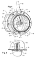
- the least complex and primary embodiment uses a handle 50 affixed by a pair of bolts 51 to the upper auger collar 33.
- the operator pulls a pin 44 in the pin bracket 43 away from a pin hole 27 in the lower auger collar 26.
- the pin 44 is biased by a spring 45 and spring pin 46 into a locked position.
- the pin 44 is removed from the pin hole 27, the operator is free to rotate the upper auger assembly 30 into any desirable position.
- the pin bracket 43 on the upper auger collar 33 and the pin holes 27 on the lower auger collar 26 typically will always be present because this lowers manufacturing costs and allows for emergency rotation of the upper auger assembly 30 in the event that the other rotation methods fail.
- an electric motor assembly 55 Basically, the electric motor drives a worm gear 61 that contacts the collar teeth 34 allowing for the upper auger assembly 30 to rotate.
- An electric motor 56 is controlled by a switch 57 positioned in the cab 2.
- a motor bracket 58 supports the electric motor 56.
- the motor 56 rotates a motor drive 59.
- the motion of the drive 59 is properly adjusted by a series of reduction gears 60.
- the reduction gear 60 drives the worm gear 61.
- the worm gear 61 meshes with the collar teeth 34 on the periphery of the upper auger collar 33.
- a worm gear support bracket 62 supports the worm gear 61. It is understood that a battery or common electric source powers the electric motor.
- the deflector end of the upper auger assembly 30 may be positioned to suit a variety of situations. During typical harvesting operations, it is desirable to position the top or deflector end 36 of the upper auger assembly 30 over the centre of the grain tank 6. While the harvester is being transported, the upper auger assembly 30 can be positioned to a transport position so that its axis is parallel to the horizon. Also because the lower auger assembly 20 remains fixed, the yield monitoring equipment available in many harvesters can be affixed to the lower auger shielding 22 without risk of movement impacting its calculations.
- the upper auger assembly may be rotated by a hydraulic motor instead of the electric motor 56.
- the roller assembly 37 may also be affixed to the lower auger collar 26 and engage a smooth collar of the upper auger assembly 30.
- the upper auger assembly 30 may equally be raised to its operative position by rotating this assembly 30 about an axis which coincides with the lower auger axis 28 This movement is realised where the lower auger collar 26 is perpendicular to the lower auger shielding 22.
Landscapes
- Life Sciences & Earth Sciences (AREA)
- Environmental Sciences (AREA)
- Threshing Machine Elements (AREA)
Abstract
Description
- This invention relates to an improvement of the intermediate grain storage on an agricultural harvesting machine. More specifically it relates to a bubble-up auger for use in a grain tank.
- Mechanical harvesting of grain has taken place for decades. However, efforts continue in the attempt to make harvesting operations more efficient and effective. A combine harvester generally includes a header, which cuts the crop. The header then moves the cut crop into a feeder house, which lifts the cut crop into the threshing, separation and cleaning areas of the combine. The grain is loosened from the stalk by a rotor or cylinder threshing system. The grain is then separated and moved and stored in an intermediate container or grain tank. The chaff and trash are deposited from the rear of the combine. The grain stored in the grain tank is eventually discharged through a grain tank unload tube. An operator usually runs these various operations from a glass-enclosed cab. Typically, the cab is located above and behind the header and feederhouse. There are a variety of agricultural combine harvesters and their operations are well known in the art. For examples of such harvesters, reference is made to US-A-4,846,198 which illustrates the conventional and twin rotor threshing and separating systems of a harvester as well as other major systems of the harvester. See also the New Holland Super Conventional Combines TX™66, TX™68, the New Holland TWIN ROTOR® combines TR®89 and TR®99 for examples of existing conventional and axial flow harvesters. US-A-4,332,262 also illustrates the primary systems of a conventional harvester. For further details regarding various agricultural harvester systems review US-A-4,522,553, US-A-4,800,711, US-A-4,866,920, US-A-4,907,402, US-A-4,967,544 and US-A-5,155,984. See also the New Holland corn head model 996 and the New Holland grain belt header model 994 for details regarding headers.
- As previously alluded to, the processed grain enters the grain tank from the separating and cleaning system by means of a clean grain elevator. How the grain has been conveyed into the grain tank has gradually evolved driven by several factors. Originally, the clean grain entered the tank from the base of the tank. Of course as the pile of grain increased, the force needed to push more grain into the grain tank increased. This damaged the grain when the pile became too heavy. To alleviate this problem, a grain tank auger was introduced. Basically, the grain tank auger would lift and deposit the grain from the clean grain elevator to the top of the grain tank. The next improvement involved the creation of the bubble up auger. The bubble-up auger allowed for even more grain to be piled into the centre of the grain tank. The bubble-up auger was typically spring biased or hydraulically driven and would constantly be rising above the pile of grain. However, grain tank sizes are increasing so much that a bubble up auger could rise quite high above the sides of the combine. This creates transport difficulties because the total height of the combine could increase to the point where the bubble-up auger would protrude above the combine contrary to various national and international transport regulations.
- The prior art illustrates these drawbacks. US-A-4,008,819 illustrates a self-raising bin loading auger for combines or a conventional spring-biased bubble-up auger. US-A-4,106,649 illustrates a floating grain bin extension for use with agricultural combine or a bubble-up auger for an even larger grain tank. US-A-Re 24,920 illustrates a grain bin unloading system. US-A-2,885,129 illustrates a gearbox and transition region positioned at the base of the a grain auger. US-A-4,029,228 illustrates another spring biased bubble-up auger. US-A-5,695,398 illustrates a folding loading auger. This single grain-loading auger is hydraulically raised and then latched into position prior to operating. Once the grain tank is full, the auger remains in an upright position creating transport issues. US-A-2.481,860 shows a spring biased grain tank unloading system. US-A-4,662,812 shows a bin unloader with an oblique pivot axis. Movable bubble-up auger typically have a hinge area between the stationary and movable portions. This area has to be sealed to avoid the return of kernels from the grain tank into the bubble-up assembly. Such seals can be optimised for one position of the auger, e.g. when fully extended, but usually provide for some leakage in the other, intermediate positions.
- It is an object of the present invention to provide for a bubble-up assembly which is movable between an operative and a transport position and remedies to the drawbacks indicated above.
- According to the invention there is provided an agricultural harvesting machine comprising:
- means for processing crop collected from a field;
- a tank for intermediate storage of processed crop material; and
- conveyor means for conveying processed crop material from said processing means to said tank;
- said conveyor means comprising:
- a stationary lower auger assembly comprising lower auger flighting mounted for rotation inside lower auger shielding;
- a movable upper auger assembly comprising upper auger flighting mounted for rotation inside upper auger shielding for discharging said processed crop material into said tank; and
- means for rotating said upper auger assembly relative to said lower auger assembly,
characterised in that said rotating means comprise
means for rotating said upper auger assembly about a
rotation axis which lies in a plane extending through the
axis of said lower auger flighting, said rotation axis
intersecting or coinciding with said lower flighting
axis. -
- Such auger is capable of being pivoted downwardly below the top level of the grain tank to allow for easy transport. As the upper auger assembly is rotated, this allows the top of the auger to be positioned in a variety of locations within the grain tank.
- The rotating means may comprise a turret system. Such embodiment is compact in volume, which is particularly advantageous when used inside a grain tank. It may be installed easily in an existing combine harvester. Such turret system may comprise one or more roller assemblies affixed to a collar on the upper or lower auger assembly and being in slideable contact with a collar on the other auger assembly. The roller assemblies hold the collars proximate to each other while allowing rotation relative to each other.
- Advantageously, the collar of the movable auger portion is oriented in a plane oblique relative to the upper auger shielding.
- The upper auger section may be pivotally manually, e.g. by means of a handle, or motor means may be provided for rotation by the operator in the cab of the harvester. Locking means, e.g. a spring-biased pin inserted through the upper and lower auger collars, can be used to secure the upper auger assembly in the operative or transport position. The operator may then raise the pin and rotate the upper auger assembly manually into the appropriate position. The pin is then urged by the spring into a hole, thereby locking the upper assembly into position.
- A hydraulic or an electric motor assembly may rotate the upper auger assembly. A switch-controlled electric motor may be used to rotate a worm gear, which meshes with a series of collar teeth positioned on the periphery of an auger collar. The upper auger collar is rotated to the appropriate position as desired by controlling the switch.
- The lower auger assembly or a transition to this lower auger may provide room for the attachment of a yield monitoring system.
- An embodiment of the present invention will now be described in further detail, by way of example, with reference to the accompanying drawings, in which:
- Figure 1 is a schematic side elevational view of a combine with structure broken away to reveal the inside of the grain tank;
- Figure 2 is an enlarged vertical sectional view of the structure visible within the grain tank in Figure 1, showing upper and lower auger assemblies;
- Figure 3 is a sectional view perpendicular to the auger collars showing a roller assembly and an electric motor assembly taken on line 3-3 of Figure 2;
- Figure 4 is a view similar to Figure 3, but showing the manual turning means embodiment;
- Figure 5 is a detailed sectional view of the roller assembly taken on the line 5-5 of Figure 3 and shown in larger scale; and
- Figure 6 is a detailed sectional view of a pin and a pin bracket taken on the line 6-6 of Figure 3 and drawn to a larger scale.
-
- Referring to the drawings, it is possible to observe the major elements and general operation of the present invention. Left and right references are used as a matter of convenience and are determined by standing at the rear of the combine and facing the forward end in the normal direction of travel. Likewise, forward and rearward are determined by normal direction of travel of the combine. Arrow D defines the typical forward direction of travel. Upward or downward orientations are relative to the ground or operating surface. Horizontal or vertical planes are also relative to ground.
- Figure 1 shows a
typical combine 1 having a pair of front wheels 8 (only one shown) and a pair of rear wheels 12 (only one shown) mounted to amain frame 15 for providing movement over the ground. At the front of the combine is aheader 5 for cutting a crop. As thecombine 1 andheader 5 are moved forward, the header cuts the grain and stalk. Theheader 5 moves the grain into its auger trough. A transverse auger pushes the grain and stalk in the auger trough to the centre of the header. The header may be positioned and re-positioned relative to the ground. The header may also be tilted to the left or right or may be positioned relatively high or low to the ground. These features are constantly being adjusted depending on the terrain and crop conditions. Moveable headers are well known and established in the art. Located at the rear centre of the header is thefeederhouse 3 or elevator. Thefeederhouse 3 moves the grain and stalks rearward into the threshing, separation and cleaning systems 4 of thecombine 1. There are a variety of different threshing, separation and cleaning systems 4 which are numerous and well known by those skilled in the art. After processing, separation and cleaning, the grain is transported by aclean grain elevator 13 upwards and dumped into theclean grain transition 25. Aturret system 10 lifts the clean grain from theclean grain transition 25 and deposits the grain at the top of agrain tank 6 located near the top of thecombine 1. At intervals, the grain is transferred from thegrain tank 6 to a transport vehicle by an unloadauger tube 7. Usually during the harvesting operations, the unloading auger remains undriven and the grain tank unloadauger tube 7 remains retracted as shown in Figure 1. However, the combine can be unloaded 'on the go'. A separate vehicle such as a truck or tractor-pulled grain cart drives beside the moving combine. The processed grain is discharged while the combine and receiving vehicle are moving. The trash or chaff is ejected from the rear of the combine by a chaff spreader at the rear 11 of thecombine 1. The operator controls thecombine 1 from thecab 2 located behind the header and at the front of the combine. From thecab 2 the operator can observe most of the various combine functions. Thecab 2 usually has a large glass window or several windows which afford the operator the maximum ability to monitor theheader 5. Thecombine 1 and various systems are powered by anengine 9 generally positioned at the rear of thecombine 1. Most of the major systems in a combine are discussed and well known in the prior art. - As previously indicated, the combine is provided with a
turret system 10 for the combine's bubble-up auger. It consists oflower auger assembly 20 and rotationally attachedupper auger assembly 30. Theupper auger assembly 30 can be rotated relative to thelower assembly 10 by means of either a handle 50 (Figure 4) or an motor assembly 55 (Figure 3) to or from a transport position 65 (Figure 2). - The
lower auger assembly 20 has lower auger shielding 22. Within the shielding 22 is the lower auger flighting 21. Alower auger gearbox 24 rotates the lower auger flighting 21 about a rotation axis 28. Typically grain exits at the top of theclean grain elevator 13, slides down theclean grain transition 25 and is lifted by the lower auger flighting 21. Attached to the lower auger shielding 22 is thelower auger collar 26. Thecollar 26 is oriented on an oblique plane relative to the axis of the cylindrically shaped auger shielding 22. The oblique plane intersects the auger shielding axis at a non-perpendicular angle. Thecollar 26 also has two diametrically opposed pin holes 27 (see Figures 3 and 4). Thelower auger assembly 20 is held in a fixed position by abrace 23. - The
upper auger assembly 30 has upper auger shielding 32 and upper auger flighting 31. The lower auger flighting 21 and upper auger flighting 31 are connected by a splined universal or U-joint 35 to allow for movement and misalignment. Attached to the upper auger shielding 32 is theupper auger collar 33. On the periphery of theupper auger collar 33 is a series ofcollar teeth 34. As like thelower auger collar 26, theupper auger collar 33 is oriented on an oblique plane relative to the shielding. On the surface of thecollar 33 is thepin bracket 43. Attached at the top of the upper auger shielding 32 is thedeflector 36. - The
lower auger collar 26 andupper auger collar 33 are connected by aroller assembly 37 attached to theupper auger collar 33. Theroller assembly 37 consists of abolt 39 andseveral washers 40 inserted through aroller hole 38 on the upper auger collar 33 (see detail Figure 5). Aroller 41 is held on the bolt by anut 42. Theroller 41 contacts and moves over the periphery of thelower auger collar 33. Thenut 42 extends above the same periphery of thelower auger collar 26 to ensure alignment between the upper 33 and lower 26 auger collars. Thisturret system 10 allows for the rotation of the completeupper auger assembly 30 about anaxis 29 which is perpendicular to the oblique plane of theauger collars lower flighting 21. Because of the orientation of the oblique plane, theturret rotation axis 29 intersects this lower rotation axis 28 at an obtuse angle. - To rotate the
upper auger assembly 30 relative to the fixedlower assembly 20, there are several possible mechanisms. The least complex and primary embodiment, shown in Figure 4, uses ahandle 50 affixed by a pair ofbolts 51 to theupper auger collar 33. The operator pulls apin 44 in thepin bracket 43 away from apin hole 27 in thelower auger collar 26. Typically thepin 44 is biased by aspring 45 andspring pin 46 into a locked position. Once thepin 44 is removed from thepin hole 27, the operator is free to rotate theupper auger assembly 30 into any desirable position. There are at least twopin holes 27 in thelower auger collar 26 to facilitate proper alignment. In the present embodiment, theholes 27 are diametrically opposed to allow movement of theupper auger assembly 30 from an operating position to the transport position. Thepin bracket 43 on theupper auger collar 33 and the pin holes 27 on thelower auger collar 26 typically will always be present because this lowers manufacturing costs and allows for emergency rotation of theupper auger assembly 30 in the event that the other rotation methods fail. - Another means for rotating the
upper auger assembly 30 involves the use of anelectric motor assembly 55. Basically, the electric motor drives aworm gear 61 that contacts thecollar teeth 34 allowing for theupper auger assembly 30 to rotate. Anelectric motor 56 is controlled by aswitch 57 positioned in thecab 2. Amotor bracket 58 supports theelectric motor 56. Themotor 56 rotates amotor drive 59. The motion of thedrive 59 is properly adjusted by a series of reduction gears 60. Thereduction gear 60 drives theworm gear 61. Theworm gear 61 meshes with thecollar teeth 34 on the periphery of theupper auger collar 33. A wormgear support bracket 62 supports theworm gear 61. It is understood that a battery or common electric source powers the electric motor. - Because of the oblique angle of the
upper collar 33 andlower auger collar 26, when theupper collar 33 rotates, the deflector end of theupper auger assembly 30 may be positioned to suit a variety of situations. During typical harvesting operations, it is desirable to position the top ordeflector end 36 of theupper auger assembly 30 over the centre of thegrain tank 6. While the harvester is being transported, theupper auger assembly 30 can be positioned to a transport position so that its axis is parallel to the horizon. Also because thelower auger assembly 20 remains fixed, the yield monitoring equipment available in many harvesters can be affixed to the lower auger shielding 22 without risk of movement impacting its calculations. - It will be obvious to those skilled in the art that various changes may be made without departing from the scope of the invention and the invention is not to be considered limited to what is illustrated in the drawings and described in the specification. For example, the upper auger assembly may be rotated by a hydraulic motor instead of the
electric motor 56. Theroller assembly 37 may also be affixed to thelower auger collar 26 and engage a smooth collar of theupper auger assembly 30. Where thelower auger assembly 20 has a non-vertical axis 28 and the axis of theupper auger assembly 30 extend at a non-perpendicular angle to the plane of itscollar 33, theupper auger assembly 30 may equally be raised to its operative position by rotating thisassembly 30 about an axis which coincides with the lower auger axis 28 This movement is realised where thelower auger collar 26 is perpendicular to the lower auger shielding 22.
Claims (14)
- An agricultural harvesting machine comprising:characterised in that said rotating means comprise means (10) for rotating said upper auger assembly about a rotation axis (29) which lies in a plane extending through the axis (28) of said lower auger flighting (31), said rotation axis (29) intersecting or coinciding with said lower flighting axis (28).means (4) for processing crop collected from a field;a tank (6) for intermediate storage of processed crop material; andconveyor means (13, 25, 20, 10, 30) for conveying processed crop material from said processing means (4) to said tank (6);said conveyor means comprising:a stationary lower auger assembly (20) comprising lower auger flighting (21) mounted for rotation inside lower auger shielding (22);a movable upper auger assembly (30) comprising upper auger flighting (31) mounted for rotation inside upper auger shielding (32) for discharging said processed crop material into said tank (6); andmeans (10) for rotating said upper auger assembly (30) relative to said lower auger assembly (20),
- An agricultural harvesting machine according to claim 1, characterised in that said conveyor means (13, 25, 20, 10, 30) further comprise an elevator (13) for conveying processed crop material from said processing means (4) to said lower auger assembly (20).
- An agricultural harvesting machine according to claim 2, characterised in that said conveyor means (13, 25, 20, 10, 30) comprise a transition (25) for the passage of processed crop material from said elevator (13) to said lower auger assembly (20).
- An agricultural harvesting machine according to claim 3, characterised in that said transition (25) or said lower auger assembly (20) is provided with a crop yield monitor.
- An agricultural harvesting machine according to any of the preceding claims, characterised in that said rotating means comprise a turret system (10) comprising:a lower auger collar (26) affixed to said lower auger assembly (20);an upper auger collar (33) affixed to said upper auger assembly (30); anda roller assembly (37) attached to one of said upper or lower auger collars (26/33) for holding said collars proximate to each other and allowing the upper auger assembly (30) to rotate relative to the lower auger assembly (20).
- An agricultural harvesting machine according to claim 5, characterised in that said roller assembly (37) comprises:a bolt (39) affixed to said one collar (26/33); anda roller (41) rotationally attached to said bolt (39) and secured by a nut (42), said roller being in slideable contact with the other of said upper or lower auger collars (26/33).
- An agricultural harvesting machine according to claim 5 or 6, characterised in that said upper auger collar (33) is oriented in a plane oblique relative to the upper auger shielding (32).
- An agricultural harvesting machine according to any of the preceding claims, characterised in that said conveyor means further comprise means (27, 43-46) for locking said upper auger assembly (30) in a fixed position to said lower auger assembly (20).
- An agricultural harvesting machine according to claim 8, when appended to any of the claims 5 to 7, characterised in that said locking means comprise a pin hole (27) in one of said upper or lower auger collars (26/33), a pin bracket (43) affixed to the other of said upper or lower auger collars (33/26), a pin (44) mounted to said bracket (43) and resilient means (45) for biasing said pin (44) to said pin hole (27).
- An agricultural harvesting machine according to any of the preceding claims, characterised in that said rotating means comprise a handle (50) affixed to said upper auger assembly (30) for rotating said upper auger assembly.
- An agricultural harvesting machine according to any of claims 5 to 7, characterised in that:one of said upper or lower auger collars (26/33) is provided with a plurality of gear teeth (34) positioned on the periphery of said one collar;said rotating means (10) comprise a worm gear (61) in rotational contact with said gear teeth (34) and means (55) for rotating said worm gear (61)
- An agricultural harvesting machine according to claim 11, characterised in that said worm gear rotating means (55) comprise a motor bracket (58) housing an electric motor (56), a switch means (57) electrically connected to said motor and a reduction gear (60) operably connected to said motor (56) and the worm gear (61).
- An agricultural harvesting machine according to any of the preceding claims, characterised in that said lower auger assembly (20) extends into said tank (6) and said machine comprises a brace (23) attached to said tank (6) for supporting said lower auger assembly (20).
- An agricultural harvesting machine according to any of the preceding claims, characterised in that:said harvesting machine is a combine harvester (1);said crop processing means comprise a threshing, separating and cleaning system (4); andsaid conveyor means comprise a bubble-up auger assembly (20, 30).
Applications Claiming Priority (2)
| Application Number | Priority Date | Filing Date | Title |
|---|---|---|---|
| US492234 | 2000-01-27 | ||
| US09/492,234 US6248015B1 (en) | 2000-01-27 | 2000-01-27 | Turret system on a bubble-up auger for an agricultural combine |
Publications (2)
| Publication Number | Publication Date |
|---|---|
| EP1120027A1 true EP1120027A1 (en) | 2001-08-01 |
| EP1120027B1 EP1120027B1 (en) | 2005-11-23 |
Family
ID=23955489
Family Applications (1)
| Application Number | Title | Priority Date | Filing Date |
|---|---|---|---|
| EP01200257A Expired - Lifetime EP1120027B1 (en) | 2000-01-27 | 2001-01-25 | Turret system on a bubble-up auger for an agricultural combine |
Country Status (4)
| Country | Link |
|---|---|
| US (1) | US6248015B1 (en) |
| EP (1) | EP1120027B1 (en) |
| AT (1) | ATE310377T1 (en) |
| DE (1) | DE60115112T2 (en) |
Cited By (2)
| Publication number | Priority date | Publication date | Assignee | Title |
|---|---|---|---|---|
| US11310962B2 (en) | 2019-04-10 | 2022-04-26 | Claas Selbstfahrende Erntemaschinen Gmbh | Harvesting machine and swivel conveyor screw therefor |
| EP4413846A1 (en) * | 2023-02-07 | 2024-08-14 | CLAAS Selbstfahrende Erntemaschinen GmbH | Harvesting machine |
Families Citing this family (15)
| Publication number | Priority date | Publication date | Assignee | Title |
|---|---|---|---|---|
| DE10153790A1 (en) * | 2001-10-31 | 2003-05-22 | Deere & Co | Conveying device for filling a grain tank of a combine harvester and return conveyor |
| CA2376380C (en) | 2002-03-12 | 2005-05-10 | Bourgault Industries Ltd. | Pivoting unloading auger |
| US7367881B2 (en) * | 2006-02-10 | 2008-05-06 | Agco Corporation | High capacity combine grain bin unload system |
| US20100016046A1 (en) * | 2008-07-16 | 2010-01-21 | Coers Bruce A | Flexible unloading tube |
| US20100209223A1 (en) | 2009-02-13 | 2010-08-19 | Unverferth Manufacturing Company, Inc. | Grain cart with folding auger |
| US20100287787A1 (en) * | 2009-05-12 | 2010-11-18 | Shelton/Hay Llc | Device and method for breaking caked grain in a storage bin |
| US8197312B2 (en) * | 2009-12-04 | 2012-06-12 | Cnh America Llc | Extension for an agricultural combine unloader tube |
| GB201213562D0 (en) * | 2012-07-31 | 2012-09-12 | Agco As | Granule conveying apparatus |
| WO2015121340A1 (en) * | 2014-02-12 | 2015-08-20 | Cnh Industrial Belgium Nv | Agricultural harvester |
| BE1022112B1 (en) | 2014-02-12 | 2016-02-16 | Cnh Industrial Belgium Nv | HARVESTER |
| US10160367B2 (en) | 2015-12-28 | 2018-12-25 | Unverferth Manufacturing Company, Inc. | Grain cart with rotatable folding auger assembly |
| DE102017003738A1 (en) * | 2017-04-19 | 2018-10-25 | Deere & Company | Auger assembly for a combine harvester |
| CN112173746B (en) * | 2020-09-04 | 2022-06-21 | 南京朗禾智能控制研究院有限公司 | Feeding device for crop hose grain elevator |
| US12120984B2 (en) * | 2021-07-15 | 2024-10-22 | Cnh Industrial America Llc | Bubble up auger for combine harvester |
| DE102023104330A1 (en) * | 2023-02-22 | 2024-08-22 | Claas Selbstfahrende Erntemaschinen Gmbh | Harvester |
Citations (15)
| Publication number | Priority date | Publication date | Assignee | Title |
|---|---|---|---|---|
| DE1155933B (en) * | 1961-07-14 | 1963-10-17 | Ybbstaler Maschb Zoidl & Merki | Discharge chute for agricultural harvesting machines, in particular flail choppers |
| FR1488605A (en) * | 1965-07-28 | 1967-07-13 | Laverda Spa Pietro | Swivel unloading device for the grain tank of a combine harvester |
| BE742766A (en) * | 1969-12-08 | 1970-05-14 | ||
| DE2036301A1 (en) * | 1969-07-25 | 1971-02-11 | Massey Ferguson GmbH, 3500 Kassel | Grain tank with an emptying conveyor, especially for combine harvesters or the like |
| US4008819A (en) | 1975-09-26 | 1977-02-22 | Allis-Chalmers Corporation | Self-raising bin loading auger for combines |
| US4029228A (en) * | 1975-09-26 | 1977-06-14 | Allis-Chalmers Corporation | Self-raising bin loading auger for combines |
| US4332262A (en) | 1979-11-14 | 1982-06-01 | Sperry Corporation | Combine harvester |
| US4522553A (en) | 1982-09-13 | 1985-06-11 | Deere & Company | Combine power boost system |
| US4800711A (en) | 1986-06-24 | 1989-01-31 | Ford New Holland, Inc. | Header for harvesting machine |
| US4866920A (en) | 1987-06-29 | 1989-09-19 | Deere & Company | Unloading auger position switch |
| DE3827277A1 (en) * | 1988-08-11 | 1990-02-15 | Deere & Co | Conveying apparatus for a collecting container |
| US4907402A (en) | 1979-08-13 | 1990-03-13 | Ford New Holland, Inc. | Unloading system |
| US4967544A (en) | 1989-01-05 | 1990-11-06 | Deere & Company | Automatic speed control system for a harvesting assembly |
| US5155984A (en) | 1991-04-24 | 1992-10-20 | Ford New Holland, Inc. | Implement height control |
| DE4419435A1 (en) * | 1994-06-03 | 1995-12-07 | Claas Ohg | Conveyor for grain tank of combine harvester |
Family Cites Families (14)
| Publication number | Priority date | Publication date | Assignee | Title |
|---|---|---|---|---|
| USRE24920E (en) | 1961-01-03 | Material handling system | ||
| US2481860A (en) | 1947-11-22 | 1949-09-13 | Desert Gold Feed Company | Grain conveyer system |
| US2885129A (en) | 1957-03-22 | 1959-05-05 | Allis Chalmers Mfg Co | Valve and outlet spout for grain bin |
| US3670913A (en) * | 1971-04-19 | 1972-06-20 | Allis Chalmers Mfg Co | Bin unloader break back system |
| US3721333A (en) * | 1971-06-09 | 1973-03-20 | Allis Chalmers | Combine grain bin unloader |
| DE2317048A1 (en) * | 1973-04-05 | 1974-10-17 | Helwig Schmitt | HARVESTER |
| US3834564A (en) * | 1973-10-23 | 1974-09-10 | Int Harvester Co | Control device for the combined operation of an unloader tube and auger clutch of a combine harvester |
| GB1539608A (en) * | 1976-06-29 | 1979-01-31 | Clayson Nv | Harvesting machines |
| US4106649A (en) | 1977-08-22 | 1978-08-15 | Allis-Chalmers Corporation | Floating grain bin extension for use with agricultural combine |
| US4428182A (en) * | 1982-04-23 | 1984-01-31 | Deere & Company | Grain handling arrangement for an articulated combine |
| US4662812A (en) | 1985-11-19 | 1987-05-05 | Deutz-Allis Corporation | Bin unloader with oblique pivot axis |
| US5516253A (en) * | 1995-01-09 | 1996-05-14 | Parham Industries Inc. | Grain cart |
| US5695398A (en) | 1996-06-21 | 1997-12-09 | Deere & Company | Foldable loading auger |
| CA2240869C (en) * | 1998-06-17 | 2005-08-23 | Bourgault Industries Ltd. | Grain cart drive assembly |
-
2000
- 2000-01-27 US US09/492,234 patent/US6248015B1/en not_active Expired - Lifetime
-
2001
- 2001-01-25 EP EP01200257A patent/EP1120027B1/en not_active Expired - Lifetime
- 2001-01-25 DE DE60115112T patent/DE60115112T2/en not_active Expired - Lifetime
- 2001-01-25 AT AT01200257T patent/ATE310377T1/en not_active IP Right Cessation
Patent Citations (15)
| Publication number | Priority date | Publication date | Assignee | Title |
|---|---|---|---|---|
| DE1155933B (en) * | 1961-07-14 | 1963-10-17 | Ybbstaler Maschb Zoidl & Merki | Discharge chute for agricultural harvesting machines, in particular flail choppers |
| FR1488605A (en) * | 1965-07-28 | 1967-07-13 | Laverda Spa Pietro | Swivel unloading device for the grain tank of a combine harvester |
| DE2036301A1 (en) * | 1969-07-25 | 1971-02-11 | Massey Ferguson GmbH, 3500 Kassel | Grain tank with an emptying conveyor, especially for combine harvesters or the like |
| BE742766A (en) * | 1969-12-08 | 1970-05-14 | ||
| US4008819A (en) | 1975-09-26 | 1977-02-22 | Allis-Chalmers Corporation | Self-raising bin loading auger for combines |
| US4029228A (en) * | 1975-09-26 | 1977-06-14 | Allis-Chalmers Corporation | Self-raising bin loading auger for combines |
| US4907402A (en) | 1979-08-13 | 1990-03-13 | Ford New Holland, Inc. | Unloading system |
| US4332262A (en) | 1979-11-14 | 1982-06-01 | Sperry Corporation | Combine harvester |
| US4522553A (en) | 1982-09-13 | 1985-06-11 | Deere & Company | Combine power boost system |
| US4800711A (en) | 1986-06-24 | 1989-01-31 | Ford New Holland, Inc. | Header for harvesting machine |
| US4866920A (en) | 1987-06-29 | 1989-09-19 | Deere & Company | Unloading auger position switch |
| DE3827277A1 (en) * | 1988-08-11 | 1990-02-15 | Deere & Co | Conveying apparatus for a collecting container |
| US4967544A (en) | 1989-01-05 | 1990-11-06 | Deere & Company | Automatic speed control system for a harvesting assembly |
| US5155984A (en) | 1991-04-24 | 1992-10-20 | Ford New Holland, Inc. | Implement height control |
| DE4419435A1 (en) * | 1994-06-03 | 1995-12-07 | Claas Ohg | Conveyor for grain tank of combine harvester |
Cited By (2)
| Publication number | Priority date | Publication date | Assignee | Title |
|---|---|---|---|---|
| US11310962B2 (en) | 2019-04-10 | 2022-04-26 | Claas Selbstfahrende Erntemaschinen Gmbh | Harvesting machine and swivel conveyor screw therefor |
| EP4413846A1 (en) * | 2023-02-07 | 2024-08-14 | CLAAS Selbstfahrende Erntemaschinen GmbH | Harvesting machine |
Also Published As
| Publication number | Publication date |
|---|---|
| EP1120027B1 (en) | 2005-11-23 |
| DE60115112D1 (en) | 2005-12-29 |
| DE60115112T2 (en) | 2006-06-08 |
| ATE310377T1 (en) | 2005-12-15 |
| US6248015B1 (en) | 2001-06-19 |
Similar Documents
| Publication | Publication Date | Title |
|---|---|---|
| EP1120027B1 (en) | Turret system on a bubble-up auger for an agricultural combine | |
| US6312329B1 (en) | Stone roll mount plate for a feederhouse on an agricultural combine | |
| EP1576868B1 (en) | Grain storage tank extension for a harvester | |
| EP2578073B1 (en) | High capacity combine grain bin unload system | |
| US20100012467A1 (en) | Tractor mounted unloading conveyor | |
| US20080261671A1 (en) | System for unloading agricultural material | |
| US4892259A (en) | Apparatus for receiving, transporting, chopping, and dispensing blocks of fodder | |
| US4157164A (en) | Forage handler | |
| US6358143B1 (en) | Pivoting grain tank on an agricultural combine | |
| JP2013192474A (en) | Combine harvester | |
| EP4147559B1 (en) | Bubble up auger for combine harvester | |
| US6367234B1 (en) | Concave shaped grain tank on an agricultural combine | |
| US4446875A (en) | Stone trap for combine harvesters | |
| US7195557B2 (en) | Discharge arrangement of an agricultural harvesting machine | |
| US5695398A (en) | Foldable loading auger | |
| US5039273A (en) | Conveyor system for a container | |
| JP5022163B2 (en) | Combine | |
| JP4945984B2 (en) | Combine | |
| JP4824988B2 (en) | Combine weeding equipment | |
| CN108925250B (en) | Combine harvester | |
| JP3517842B2 (en) | Combine | |
| US20250331460A1 (en) | Rotary pivot mechanism for conveyor of sugarcane harvester | |
| KR101869467B1 (en) | Agricultural baler with horizontal control device | |
| JP5347533B2 (en) | Combine grain raising device | |
| JP4110705B2 (en) | Combine |
Legal Events
| Date | Code | Title | Description |
|---|---|---|---|
| PUAI | Public reference made under article 153(3) epc to a published international application that has entered the european phase |
Free format text: ORIGINAL CODE: 0009012 |
|
| AK | Designated contracting states |
Kind code of ref document: A1 Designated state(s): AT BE CH CY DE DK ES FI FR GB GR IE IT LI LU MC NL PT SE TR |
|
| AX | Request for extension of the european patent |
Free format text: AL;LT;LV;MK;RO;SI |
|
| 17P | Request for examination filed |
Effective date: 20020125 |
|
| AKX | Designation fees paid |
Free format text: AT BE CH CY DE DK ES FI FR GB GR IE IT LI LU MC NL PT SE TR |
|
| RAP1 | Party data changed (applicant data changed or rights of an application transferred) |
Owner name: CNH BELGIUM N.V. |
|
| 17Q | First examination report despatched |
Effective date: 20040402 |
|
| GRAP | Despatch of communication of intention to grant a patent |
Free format text: ORIGINAL CODE: EPIDOSNIGR1 |
|
| GRAS | Grant fee paid |
Free format text: ORIGINAL CODE: EPIDOSNIGR3 |
|
| GRAA | (expected) grant |
Free format text: ORIGINAL CODE: 0009210 |
|
| AK | Designated contracting states |
Kind code of ref document: B1 Designated state(s): AT BE CH CY DE DK ES FI FR GB GR IE IT LI LU MC NL PT SE TR |
|
| PG25 | Lapsed in a contracting state [announced via postgrant information from national office to epo] |
Ref country code: NL Free format text: LAPSE BECAUSE OF FAILURE TO SUBMIT A TRANSLATION OF THE DESCRIPTION OR TO PAY THE FEE WITHIN THE PRESCRIBED TIME-LIMIT Effective date: 20051123 Ref country code: AT Free format text: LAPSE BECAUSE OF FAILURE TO SUBMIT A TRANSLATION OF THE DESCRIPTION OR TO PAY THE FEE WITHIN THE PRESCRIBED TIME-LIMIT Effective date: 20051123 Ref country code: FI Free format text: LAPSE BECAUSE OF FAILURE TO SUBMIT A TRANSLATION OF THE DESCRIPTION OR TO PAY THE FEE WITHIN THE PRESCRIBED TIME-LIMIT Effective date: 20051123 Ref country code: CH Free format text: LAPSE BECAUSE OF FAILURE TO SUBMIT A TRANSLATION OF THE DESCRIPTION OR TO PAY THE FEE WITHIN THE PRESCRIBED TIME-LIMIT Effective date: 20051123 Ref country code: BE Free format text: LAPSE BECAUSE OF FAILURE TO SUBMIT A TRANSLATION OF THE DESCRIPTION OR TO PAY THE FEE WITHIN THE PRESCRIBED TIME-LIMIT Effective date: 20051123 Ref country code: LI Free format text: LAPSE BECAUSE OF FAILURE TO SUBMIT A TRANSLATION OF THE DESCRIPTION OR TO PAY THE FEE WITHIN THE PRESCRIBED TIME-LIMIT Effective date: 20051123 |
|
| REG | Reference to a national code |
Ref country code: GB Ref legal event code: FG4D |
|
| REG | Reference to a national code |
Ref country code: CH Ref legal event code: EP |
|
| REF | Corresponds to: |
Ref document number: 60115112 Country of ref document: DE Date of ref document: 20051229 Kind code of ref document: P |
|
| REG | Reference to a national code |
Ref country code: IE Ref legal event code: FG4D |
|
| PG25 | Lapsed in a contracting state [announced via postgrant information from national office to epo] |
Ref country code: IE Free format text: LAPSE BECAUSE OF NON-PAYMENT OF DUE FEES Effective date: 20060125 |
|
| PG25 | Lapsed in a contracting state [announced via postgrant information from national office to epo] |
Ref country code: LU Free format text: LAPSE BECAUSE OF NON-PAYMENT OF DUE FEES Effective date: 20060131 Ref country code: MC Free format text: LAPSE BECAUSE OF NON-PAYMENT OF DUE FEES Effective date: 20060131 |
|
| PG25 | Lapsed in a contracting state [announced via postgrant information from national office to epo] |
Ref country code: SE Free format text: LAPSE BECAUSE OF FAILURE TO SUBMIT A TRANSLATION OF THE DESCRIPTION OR TO PAY THE FEE WITHIN THE PRESCRIBED TIME-LIMIT Effective date: 20060223 Ref country code: GR Free format text: LAPSE BECAUSE OF FAILURE TO SUBMIT A TRANSLATION OF THE DESCRIPTION OR TO PAY THE FEE WITHIN THE PRESCRIBED TIME-LIMIT Effective date: 20060223 Ref country code: DK Free format text: LAPSE BECAUSE OF FAILURE TO SUBMIT A TRANSLATION OF THE DESCRIPTION OR TO PAY THE FEE WITHIN THE PRESCRIBED TIME-LIMIT Effective date: 20060223 |
|
| PG25 | Lapsed in a contracting state [announced via postgrant information from national office to epo] |
Ref country code: ES Free format text: LAPSE BECAUSE OF FAILURE TO SUBMIT A TRANSLATION OF THE DESCRIPTION OR TO PAY THE FEE WITHIN THE PRESCRIBED TIME-LIMIT Effective date: 20060306 |
|
| PG25 | Lapsed in a contracting state [announced via postgrant information from national office to epo] |
Ref country code: PT Free format text: LAPSE BECAUSE OF FAILURE TO SUBMIT A TRANSLATION OF THE DESCRIPTION OR TO PAY THE FEE WITHIN THE PRESCRIBED TIME-LIMIT Effective date: 20060424 |
|
| NLV1 | Nl: lapsed or annulled due to failure to fulfill the requirements of art. 29p and 29m of the patents act | ||
| REG | Reference to a national code |
Ref country code: CH Ref legal event code: PL |
|
| ET | Fr: translation filed | ||
| PLBE | No opposition filed within time limit |
Free format text: ORIGINAL CODE: 0009261 |
|
| STAA | Information on the status of an ep patent application or granted ep patent |
Free format text: STATUS: NO OPPOSITION FILED WITHIN TIME LIMIT |
|
| REG | Reference to a national code |
Ref country code: IE Ref legal event code: MM4A |
|
| 26N | No opposition filed |
Effective date: 20060824 |
|
| PG25 | Lapsed in a contracting state [announced via postgrant information from national office to epo] |
Ref country code: TR Free format text: LAPSE BECAUSE OF FAILURE TO SUBMIT A TRANSLATION OF THE DESCRIPTION OR TO PAY THE FEE WITHIN THE PRESCRIBED TIME-LIMIT Effective date: 20051123 |
|
| PG25 | Lapsed in a contracting state [announced via postgrant information from national office to epo] |
Ref country code: CY Free format text: LAPSE BECAUSE OF FAILURE TO SUBMIT A TRANSLATION OF THE DESCRIPTION OR TO PAY THE FEE WITHIN THE PRESCRIBED TIME-LIMIT Effective date: 20051123 |
|
| REG | Reference to a national code |
Ref country code: DE Ref legal event code: R082 Ref document number: 60115112 Country of ref document: DE Representative=s name: PATENTANWAELTE WALLACH, KOCH & PARTNER, DE |
|
| REG | Reference to a national code |
Ref country code: DE Ref legal event code: R082 Ref document number: 60115112 Country of ref document: DE Representative=s name: PATENTANWAELTE WALLACH, KOCH, DR. HAIBACH, FEL, DE Effective date: 20140428 Ref country code: DE Ref legal event code: R081 Ref document number: 60115112 Country of ref document: DE Owner name: CNH INDUSTRIAL BELGIUM NV, BE Free format text: FORMER OWNER: CNH BELGIUM NV, ZEDELGEM, BE Effective date: 20140428 Ref country code: DE Ref legal event code: R082 Ref document number: 60115112 Country of ref document: DE Representative=s name: PATENTANWAELTE WALLACH, KOCH & PARTNER, DE Effective date: 20140428 |
|
| REG | Reference to a national code |
Ref country code: FR Ref legal event code: CD Owner name: CNH INDUSTRIAL BELGIUM NV Effective date: 20140725 |
|
| REG | Reference to a national code |
Ref country code: FR Ref legal event code: PLFP Year of fee payment: 15 |
|
| PGFP | Annual fee paid to national office [announced via postgrant information from national office to epo] |
Ref country code: DE Payment date: 20150131 Year of fee payment: 15 |
|
| PGFP | Annual fee paid to national office [announced via postgrant information from national office to epo] |
Ref country code: GB Payment date: 20150119 Year of fee payment: 15 Ref country code: FR Payment date: 20150119 Year of fee payment: 15 |
|
| PGFP | Annual fee paid to national office [announced via postgrant information from national office to epo] |
Ref country code: IT Payment date: 20160105 Year of fee payment: 16 |
|
| REG | Reference to a national code |
Ref country code: DE Ref legal event code: R119 Ref document number: 60115112 Country of ref document: DE |
|
| GBPC | Gb: european patent ceased through non-payment of renewal fee |
Effective date: 20160125 |
|
| REG | Reference to a national code |
Ref country code: FR Ref legal event code: ST Effective date: 20160930 |
|
| PG25 | Lapsed in a contracting state [announced via postgrant information from national office to epo] |
Ref country code: DE Free format text: LAPSE BECAUSE OF NON-PAYMENT OF DUE FEES Effective date: 20160802 Ref country code: GB Free format text: LAPSE BECAUSE OF NON-PAYMENT OF DUE FEES Effective date: 20160125 |
|
| PG25 | Lapsed in a contracting state [announced via postgrant information from national office to epo] |
Ref country code: FR Free format text: LAPSE BECAUSE OF NON-PAYMENT OF DUE FEES Effective date: 20160201 |
|
| PG25 | Lapsed in a contracting state [announced via postgrant information from national office to epo] |
Ref country code: IT Free format text: LAPSE BECAUSE OF NON-PAYMENT OF DUE FEES Effective date: 20170125 |