EP1119977B1 - Apparatus and method for data partitioning to improve error resilience - Google Patents
Apparatus and method for data partitioning to improve error resilience Download PDFInfo
- Publication number
- EP1119977B1 EP1119977B1 EP99950216.4A EP99950216A EP1119977B1 EP 1119977 B1 EP1119977 B1 EP 1119977B1 EP 99950216 A EP99950216 A EP 99950216A EP 1119977 B1 EP1119977 B1 EP 1119977B1
- Authority
- EP
- European Patent Office
- Prior art keywords
- segment
- sub
- unit
- packet
- payload
- Prior art date
- Legal status (The legal status is an assumption and is not a legal conclusion. Google has not performed a legal analysis and makes no representation as to the accuracy of the status listed.)
- Expired - Lifetime
Links
Images


Classifications
-
- H—ELECTRICITY
- H04—ELECTRIC COMMUNICATION TECHNIQUE
- H04N—PICTORIAL COMMUNICATION, e.g. TELEVISION
- H04N19/00—Methods or arrangements for coding, decoding, compressing or decompressing digital video signals
- H04N19/65—Methods or arrangements for coding, decoding, compressing or decompressing digital video signals using error resilience
- H04N19/68—Methods or arrangements for coding, decoding, compressing or decompressing digital video signals using error resilience involving the insertion of resynchronisation markers into the bitstream
-
- H—ELECTRICITY
- H04—ELECTRIC COMMUNICATION TECHNIQUE
- H04N—PICTORIAL COMMUNICATION, e.g. TELEVISION
- H04N19/00—Methods or arrangements for coding, decoding, compressing or decompressing digital video signals
- H04N19/10—Methods or arrangements for coding, decoding, compressing or decompressing digital video signals using adaptive coding
- H04N19/169—Methods or arrangements for coding, decoding, compressing or decompressing digital video signals using adaptive coding characterised by the coding unit, i.e. the structural portion or semantic portion of the video signal being the object or the subject of the adaptive coding
- H04N19/186—Methods or arrangements for coding, decoding, compressing or decompressing digital video signals using adaptive coding characterised by the coding unit, i.e. the structural portion or semantic portion of the video signal being the object or the subject of the adaptive coding the unit being a colour or a chrominance component
-
- H—ELECTRICITY
- H04—ELECTRIC COMMUNICATION TECHNIQUE
- H04N—PICTORIAL COMMUNICATION, e.g. TELEVISION
- H04N19/00—Methods or arrangements for coding, decoding, compressing or decompressing digital video signals
- H04N19/60—Methods or arrangements for coding, decoding, compressing or decompressing digital video signals using transform coding
- H04N19/61—Methods or arrangements for coding, decoding, compressing or decompressing digital video signals using transform coding in combination with predictive coding
-
- H—ELECTRICITY
- H04—ELECTRIC COMMUNICATION TECHNIQUE
- H04N—PICTORIAL COMMUNICATION, e.g. TELEVISION
- H04N19/00—Methods or arrangements for coding, decoding, compressing or decompressing digital video signals
- H04N19/60—Methods or arrangements for coding, decoding, compressing or decompressing digital video signals using transform coding
- H04N19/63—Methods or arrangements for coding, decoding, compressing or decompressing digital video signals using transform coding using sub-band based transform, e.g. wavelets
- H04N19/64—Methods or arrangements for coding, decoding, compressing or decompressing digital video signals using transform coding using sub-band based transform, e.g. wavelets characterised by ordering of coefficients or of bits for transmission
- H04N19/645—Methods or arrangements for coding, decoding, compressing or decompressing digital video signals using transform coding using sub-band based transform, e.g. wavelets characterised by ordering of coefficients or of bits for transmission by grouping of coefficients into blocks after the transform
-
- H—ELECTRICITY
- H04—ELECTRIC COMMUNICATION TECHNIQUE
- H04N—PICTORIAL COMMUNICATION, e.g. TELEVISION
- H04N19/00—Methods or arrangements for coding, decoding, compressing or decompressing digital video signals
- H04N19/60—Methods or arrangements for coding, decoding, compressing or decompressing digital video signals using transform coding
- H04N19/63—Methods or arrangements for coding, decoding, compressing or decompressing digital video signals using transform coding using sub-band based transform, e.g. wavelets
- H04N19/64—Methods or arrangements for coding, decoding, compressing or decompressing digital video signals using transform coding using sub-band based transform, e.g. wavelets characterised by ordering of coefficients or of bits for transmission
- H04N19/647—Methods or arrangements for coding, decoding, compressing or decompressing digital video signals using transform coding using sub-band based transform, e.g. wavelets characterised by ordering of coefficients or of bits for transmission using significance based coding, e.g. Embedded Zerotrees of Wavelets [EZW] or Set Partitioning in Hierarchical Trees [SPIHT]
-
- H—ELECTRICITY
- H04—ELECTRIC COMMUNICATION TECHNIQUE
- H04N—PICTORIAL COMMUNICATION, e.g. TELEVISION
- H04N19/00—Methods or arrangements for coding, decoding, compressing or decompressing digital video signals
- H04N19/65—Methods or arrangements for coding, decoding, compressing or decompressing digital video signals using error resilience
- H04N19/66—Methods or arrangements for coding, decoding, compressing or decompressing digital video signals using error resilience involving data partitioning, i.e. separation of data into packets or partitions according to importance
-
- H—ELECTRICITY
- H04—ELECTRIC COMMUNICATION TECHNIQUE
- H04N—PICTORIAL COMMUNICATION, e.g. TELEVISION
- H04N19/00—Methods or arrangements for coding, decoding, compressing or decompressing digital video signals
- H04N19/70—Methods or arrangements for coding, decoding, compressing or decompressing digital video signals characterised by syntax aspects related to video coding, e.g. related to compression standards
-
- H—ELECTRICITY
- H04—ELECTRIC COMMUNICATION TECHNIQUE
- H04N—PICTORIAL COMMUNICATION, e.g. TELEVISION
- H04N19/00—Methods or arrangements for coding, decoding, compressing or decompressing digital video signals
- H04N19/10—Methods or arrangements for coding, decoding, compressing or decompressing digital video signals using adaptive coding
- H04N19/102—Methods or arrangements for coding, decoding, compressing or decompressing digital video signals using adaptive coding characterised by the element, parameter or selection affected or controlled by the adaptive coding
- H04N19/13—Adaptive entropy coding, e.g. adaptive variable length coding [AVLC] or context adaptive binary arithmetic coding [CABAC]
-
- H—ELECTRICITY
- H04—ELECTRIC COMMUNICATION TECHNIQUE
- H04N—PICTORIAL COMMUNICATION, e.g. TELEVISION
- H04N19/00—Methods or arrangements for coding, decoding, compressing or decompressing digital video signals
- H04N19/65—Methods or arrangements for coding, decoding, compressing or decompressing digital video signals using error resilience
-
- H—ELECTRICITY
- H04—ELECTRIC COMMUNICATION TECHNIQUE
- H04N—PICTORIAL COMMUNICATION, e.g. TELEVISION
- H04N19/00—Methods or arrangements for coding, decoding, compressing or decompressing digital video signals
- H04N19/85—Methods or arrangements for coding, decoding, compressing or decompressing digital video signals using pre-processing or post-processing specially adapted for video compression
- H04N19/89—Methods or arrangements for coding, decoding, compressing or decompressing digital video signals using pre-processing or post-processing specially adapted for video compression involving methods or arrangements for detection of transmission errors at the decoder
Landscapes
- Engineering & Computer Science (AREA)
- Multimedia (AREA)
- Signal Processing (AREA)
- Compression Or Coding Systems Of Tv Signals (AREA)
- Detection And Prevention Of Errors In Transmission (AREA)
Description
- This application claims the benefit of
U.S. Provisional Application No. 60/103,081 filed on October 5, 1998 - The invention relates to data partitioning in the field of digital multimedia communications. More particularly, the invention relates to a data partitioning method that improves error resilience, e.g., when applied to the entropy coding/decoding of hierarchical subband decomposed coefficients, e.g., wavelet transform coefficients.
- In the field of digital multimedia communications, data streams carrying video, audio, timing and control data are packaged into various "packets". Generally, a packet is a group of binary digits that include data and control elements which are switched and transmitted as a composite whole. The data, control elements and other information are arranged in various specific formats.
- Examples of such formats are disclosed in various international Standards. These standards include, but are not limited to, the Moving Picture Experts Group Standards (e.g., MPEG-1 (11172-*), MPEG-2 (13818-*) and MPEG-4 (14496-*)), H.261 and H.263. For example, MPEG defines a packet as consisting of a header followed by a number of contiguous bytes (payload) from an "elementary data stream". An elementary stream is simply a generic term for one of the coded video, coded audio or other coded bitstreams. More specifically, an MPEG-2 "transport stream" packet comprises a header, which may be four (4) or more bytes long with a payload having a maximum length of 184 bytes. Transport stream packets are part of one or more programs that are assembled into a transport stream. The transport stream is then transmitted over a channel with a particular transfer rate.
- However, transmission of packets over a noisy communication channel, e.g., wireless communication, may cause corruption in the packets received by a receiver/decoder. Since some data streams or bitstreams carry compressed data that are correlated in a manner such that partial loss of a packet may cause the receiver/decoder to discard the entire packet. Namely, compression methods are useful for representing information as accurately as possible with a minimum number of bits and thus minimizing the amount of data that must be stored or transmitted. For example, to further increase compression efficiency, some compression methods employ "significance-based" information, e.g., a significance map-value model, to indicate to a receiver/decoder the significance of the transmitted information or absence of transmitted information. The "significance-based" information is often previously defined, e.g., using symbols, such that the receiver/decoder is able to decipher additional information from the transmitted information. However, the loss of compressed data such as "significance-based" information often results in substantial errors when a receiver/decoder attempts to decompress or decode the corrupted data.
- Second, another compression technique involves the use of entropy encoders, e.g., arithmetic and/or variable-length coder (VLC), that encodes a symbol in accordance with the symbol's probability density. Namely, the encoder will generally assign a shorter code word for a symbol that has a higher probability density, whereas a longer code word is assigned for a symbol that has a lower probability density, thereby reducing the total number of coding bits that are necessary to encode a data stream. Unfortunately, a corrupted packet that carries entropy encoded data may often go undetected until the entire packet is decoded. In fact, once the error is detected, the entire packet is often discarded, since one characteristics of an arithmetic encoder/decoding system is that every decoded symbol is treated as a valid symbol. Since errors are often detected from other symptoms, e.g., misalignment of the packets and so on, the decoder is often unable to distinguish where the error lies in the corrupted packet.
- Additionally, another compression techniques involves the transformation of an input image into transform coefficients using hierarchical subband decomposition. For example, a useful compression technique appears in the Proceedings of the International Conference on Acoustics, Speech and Signal Processing, San Francisco, Cal. March 1992, volume IV, pages 657-660, where there is disclosed a signal compression system which applies a hierarchical subband decomposition, or wavelet transform, followed by the hierarchical successive approximation entropy-coded quantizer. A wavelet pyramid, also known as critically sampled quadrature-mirror filter (QMF) subband representation, is a specific type of multiresolution hierarchical subband representation of an image.
- More specifically, in a hierarchical subband system, with the exception of the highest frequency subbands, every coefficient at a given scale can be related to a set of coefficients at the next finer scale of similar orientation according to a structure called a wavelet tree. The coefficients at the coarsest scale will be called the parent nodes, and all coefficients corresponding to the same spatial or temporal location at the next finer scale of similar orientation will be called child nodes.
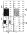
- A typical method of coding these transform coefficients is in "tree depth scan order as shown in
FIG. 1 , where an image is decomposed into three levels of resolution. Specifically, the wavelet coefficients are coded in tree blocks fashion, where each tree block is represented by three separate "texture units" shown with different shadings. Each texture unit is representative of a tree structure starting from the lowest or coarsest AC band to the highest or finest AC band coefficients. - In real life operation, one or more texture units may be corrupted or lost when transmitted over a noisy channel. The loss of these texture units or texture packets often results in noticeable errors in the decoded image.
- Therefore, there is a need in the art for an apparatus and method for data partitioning that improves error resilience, e.g., when applied to the entropy coding/decoding of hierarchical subband decomposed coefficients, e.g., wavelet transform coefficients.
- The paper "Robust wavelet zerotree image compression with fixed-length packetisation" (Rogers J K ET AL), Data Compression Conference, US, IEEE Computer Society Press, Los Apamitos, CA, published 30 March 1998, describes an image compression algorithm in which the output of a wavelet zerotree-style coder is manipulated into fixed-length segments. The segments are independently decodable, and errors occurring in one segment do not propagate into any other.
- Furthermore, the European patent application
EP-A-0860999 (Tokyo Shibaura Electric Co), entitled "Information transmitting method, encoder/decoder of information transmitting system using the method, and encoding multiplexer/decoding inverse multiplexer", published 26 August 1998, discloses an information transmission system, where error robustness is provided for the bit stream itself so that decoding processing can be properly performed even in the event of an error in important information such as header information. - particular aspects of the invention are set out in the independent claims.
- In one embodiment of the present invention, an apparatus and a method for partitioning data to improve error resilience, e.g., in a coding/decoding system that employs entropy coding, is disclosed. : Specifically, one or more segment markers (symbols) are entropy encoded along with the bitstream (payload) into a packet.
- The placement of the segment marker into the packet is dependent upon whether the encoding of a number of "sub-units" have exceeded a "target segment length". Namely, a segment marker is encoded into the packet at an approximate interval that is defined to be greater than or equal to the target segment length.
- Additionally, the placement of the segment marker into the packet is also limited to being located at a juncture between two encoded "sub-units". A sub-unit is defined as a logical coding sub-unit of a texture unit that is being encoded into the packet. Since texture units can be defined in a number of different manners, the present invention also presents a number of sub-units having different defined structures. One advantage in such limiting of the placement of a segment marker to be between sub-units is that it provides an easily identifiable point for the decoder to start searching for the segment marker.
- Once the segment markers are encoded as described, the decoder can now readily determine if a current packet is corrupted. Namely, if the decoder is able to decode an uncorrupted segment marker as anticipated in the packet, then all the bits up to the point of the segment marker are considered also to be uncorrupted.
- However, if the decoder is unable to decode a segment marker as anticipated in the packet, then all the bits from a prior decoded segment marker up to the point of the corrupted or missing segment marker must be corrupted to some extent. This set of identified bits in the packet are then discarded as corrupted bits, i.e., the bits starting from the last correctly decoded segment marker/packet header to the end of the packet are discarded. However, instead of discarding the entire packet as known in the prior art, only a portion of the packet is now discarded, thereby improving error resilience.
- The present invention provides several advantages. First, the use of an encoded segment marker reduces the amount of overhead, i.e., shorter code word, when compared to other packet markers such as adding additional Resynch markers. Second, no extra information is needed in the packet header to communicate the existence of the segment marker. Third, reinitialization of the entropy encoder is not required.
- The teachings of the present invention can be readily understood by considering the following detailed description in conjunction with the accompanying drawings, in which:
-
FIG. 1 is a schematic illustration of the parent-child dependencies of subbands in an image decomposed to three levels within a wavelet tree having a plurality of texture units as used in the prior art; -
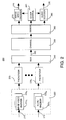
FIG. 2 depicts a block diagram of a simplified packet stream system of the present invention; -
FIG. 3 depicts a block diagram of a packet structure having an error; -
FIG. 4 depicts a block diagram of a packet structure having an error that is disposed between segment markers of the present invention; -
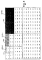
FIG. 5 is a schematic illustration of a sub-unit for a texture unit that is defined in accordance with a tree-depth scanning order; -
FIG. 6 is a schematic illustration of a sub-unit for a texture unit that is defined in accordance with a layer-by-layer scanning order; -
FIG. 7 is a schematic illustration of a second embodiment of a sub-unit for a texture unit that is defined in accordance with a layer-by-layer scanning order; -
FIG. 8 is a schematic illustration of a sub-unit for a texture unit that is defined in accordance with a band-by-band scanning order; -
FIG. 9 is a schematic illustration of a context formation for an arithmetic encoder; -
FIG. 10 illustrates a block diagram of an encoding system and a decoding system of the present invention; and -
FIG. 11 illustrates a flowchart of the present data partitioning method. - To facilitate understanding, identical reference numerals have been used, where possible, to designate identical elements that are common to the figures.
-
FIG. 2 depicts a block diagram of a simplified structure of apacket stream system 200 of the present invention. For illustration, a data stream such as a "transport stream" as defined in accordance with the MPEG standards is used in the packet stream system illustrated inFIG. 2 . Although the present invention is described below using the transport stream as an example, those skilled in the art will realize that the present invention can be applied to any packet streams, e.g., an MPEG "program stream" or any other packet streams in accordance with other formats. Furthermore, although the present invention is described below using the term "stream", it should be understood that the various operations described below may be performed on the entire stream or portion thereof. -
System 200 includes an image/video encoder 220 for receiving and encodingvideo data 210 into an elementary video bitstream. Thevideo encoder 220 is an encoder capable of generating hierarchical subband decomposed coefficients, e.g., wavelet coefficients with or without significance-based information. The image/video encoder 220 may be a single image encoder, e.g., a Joint Photographic Experts Group (JPEG) encoder, GIF, PICT, and the like, or an encoder for an image sequence (video), e.g., a block-based or wavelet-based image encoder operating in accordance with an MPEG standard. Throughout this disclosure the terms image sequence, images, and video are used interchangeably. In its broadest sense, the invention operates in cooperation with any form of image or image sequence encoder that would benefit from the present packet structures to provide error resilience. - One example of such an encoder is the Sarnoff Very Low Bit Rate (VLBR) encoder, which is disclosed and claimed in
US patent 5,764,805 (issued on June 9, 1998 ), and is herein incorporated by reference. Other examples of such encoders are disclosed in U.S. patent application entitled "Apparatus And Method For Encoding Zerotrees Generated By A Wavelet-Based Coding Technique" (filed on October 24, 1996 with serial number08/736,114 ), which is herein incorporated by reference. - Similarly, the system may include an
audio encoder 222 for receiving and encodingaudio data 212 into an elementary audio bitstream. However, those skilled in the art will realize that a plurality of image/video encoders 220n andaudio encoders 222n can be employed to produce a plurality of elementary bitstreams. In fact, the plurality of video and audio encoders can be collectively represented by aserver 225, which may employ various encoders and/or may simply contain a plurality (or a library) of stored elementary streams in various storage media. Generally, the output of such server contains interleaved program streams. - In turn, these bitstreams are sent to
packetizers 230 of the present invention, where the elementary bitstreams are converted into packets. Information for using the packets independently of the transport stream may be added when the packets are formed. Thus, non-audio/video data are allowed, but they are not shown inFIG. 2 . It should be noted that although in a preferred embodiment, the present encoder and the packetizer are implemented in a single module, those skilled in the art will realize that the functions performed by the encoder and the packetizer can be jointly or separately implemented as required by a particular application. - The packets are received and multiplexed by the
transport stream multiplexer 240 to produce atransport stream 245. Packets constructed from elementary streams that form a program (a group of "Packet Identifiers" (PIDs) with associated video and audio data) generally share a common time base. Thus, the transport stream may contain one or more programs with one or more independent time bases, where the time bases are used for synchronized presentation. The time bases of different programs within a transport stream may be different. - The
transport stream 245 is transmitted over atransmission channel 250, which may further incorporate separate channel specific encoder and decoder (not shown). Next, thetransport stream 245 is demultiplexed and decoded by atransport stream demultiplexor 260, where the elementary streams serve as inputs tovideo decoder 270 andaudio decoder 290, whose outputs are decodedvideo signals 275 andaudio signals 295, respectively. - Furthermore, timing information is also extracted by the
transport stream demultiplexor 260 and delivered toclock control 280 for synchronizing the video and audio decoders with each other and with the channel. Synchronization of the decoders with the channel is accomplished through the use of the "Program Clock Reference" (PCR) in the transport stream. The PCR is a time stamp encoding the timing of the bitstream itself and is used to derive the decoder timing. - As discussed above, the
packetizer 230 organizes the bitstream from the encoder into packets for transmission. If thetransmission channel 250 is noisy, the transmitted packets can be corrupted or partially lost. Although the present invention describes a method below for manipulating a bitstream to form a particular packet structure within apacketizer 230, it should be understood that this operation can also be performed within theencoder 220 itself. As such, the implementation of the present invention is a matter of designer choice. - Error resilience is particularly important for packets carrying hierarchically decomposed information, i.e., hierarchical subband decomposed coefficients. Hierarchical subband decomposition provides a multi-resolution representation of an image. For example, the image is first decomposed into four subbands, LL, LH, HL, HH, each representing approximately a quarter of the entire frequency band. To obtain the next coarser scale image representation, the LL band is further divided into four subbands. The process can be repeated to form a hierarchical subband pyramid. It should be understood that hierarchical subband decomposition can apply any number of subband decompositions. Hierarchical subband decomposed coefficients can be packetized into units called "texture packets" for error resilience. A texture packet consists of one or more coding units, named "texture units". Namely, if the texture unit is packetized into a single packet, then the packet is referred to as a texture packet. Examples of various texture unit structures are disclosed in US patent application entitled "Apparatus And Method For Forming A Coding Unit" with attorney docket 13151, which is herein incorporated by reference and is filed simultaneously herewith.
-
FIG. 3 depicts a block diagram of apacket structure 300 having aheader 310 and apayload 320 carrying a bitstream that is representative of coded data, e.g., entropy coded hierarchical subband decomposed coefficients. The header carries a Resynch marker that allows a decoder to synchronize the decoding process with the incoming packets, e.g., the start of a new packet. Specifically, in noisy channels, the addition of resynchronization markers at the beginning of each sequence (in JPEG terminology) or packet allows the resynchronization of the decoding process at the next Resynch marker if an error is encountered. -
FIG. 3 also illustrates anerror 330 located somewhere within the payload of the packet that may have been caused by a noisy channel. As discussed above, the location and, at times, the existence of the error often goes undetected until the entire packet is decoded. Once the error is detected, the decoder is often unable to locate and correct the error due to the nature of entropy encoding and is forced to discard theentire payload 320 of thepacket 300. For example, all the coefficient values are set to zero in the erroneous sequence or packet. The decoder must then rely on various error concealment methods to replace the missing data in the discarded payload. Examples of such error concealment methods are disclosed in US patent application entitled "Apparatus And Method For Error Concealment For Hierarchical Subband Coding And Decoding" with attorney docket 13153, which is herein incorporated by reference and is filed simultaneously herewith. - To aid in the understanding of the problem of having an undetected error in a packet carrying entropy coded information, an example of an efficient context-based entropy encoding method used in
encoder 220 is illustrated inFIG. 9 . Namely, context modeling is used to determine the probability model that is used to entropy code each coefficient.FIG. 9 illustrates a novel context model where a coefficient, shown as "x" 910 with coordinate (i,j) is entropy encoded as follows:
where
Namely, the new context model is premised on its three neighbors shown as "o", 920-940. It should be noted that a total of eight (8) context models can be formed based on the significance of these three neighbors in accordance withequation 1 and the order of the three neighbors in accordance to equation (1) can be interchanged as desired. -
FIG. 9 illustrates one example of the correlation that is employed in an entropy coder. This complex correlation is the source of the present criticality where if a portion of a packet is corrupted, then the entire packet is often discarded since it is very difficult to ascertain the exact nature of the error and the location of the error in the packet. - In contrast,
FIG. 4 now depicts a block diagram of apacket structure 400 having aheader 410 and a plurality ofpayload segments 420a-420b (herein referred to as "segments") carrying a bitstream that is representative of coded data, e.g., entropy coded hierarchical subband decomposed coefficients. Thepayload segments 420a-420b are separated bysegment markers 425 of the present invention. Thus, in this example, theerror 430 is now disposed between twosegment markers 425. However, it should be understood that the error may occur within a segment that is between a header and a segment marker or a segment marker and an end of packet marker or a header for the next packet (not shown). - In brief, the present invention codes an extra symbol (representative of the segment marker) whenever a segment of the bitstream in a packet exceeds a "predefined length" and is at a "distinguishable location" in the encoded image. An example of the predefined length is approximately 512 bits. It should be noted that this predefined length can be modified in accordance with a particular application or a particular packet format. Thus, an
error 430 can be identified with respect to its location if an anticipated segment marker is not present at the "predefined length" and at a predetermined location within the encoded image. For example, if theerror 430 is detected, then the decoder can then only discard thepayload segment 420b up to thesegment marker 425, thereby retainingpayload segment 420a. This ability to retain even a small portion of the payload of a packet will greatly improve the error resilience of an encoding/decoding system. - The extra symbol can be a symbol that is different from any other possible symbols or it can be a symbol in an existing symbol set that is being used by the encoder that is generating the bitstream. For example, the segment marker can be selected as having a certain bit pattern, e.g., "0101". Nevertheless, the extra symbol is entropy encoded in the same manner as other symbols that are encoded to form the payload of the packet. Generally, if a symbol is chosen from an existing symbol set, it is preferable to select a rarely occurring symbol to represent the segment marker.
- In one embodiment, if the "predefined length" is "N" bits, and the image is encoded in a raster scan order line by line, the bitstream length can be checked at the end of each line of the image. i.e., a "distinguishable location" in the encoded image. If at the end of the ith line, the bitstream length exceeds "N" bits, and the end of a texture unit has not been reached (i.e., not at the end of a packet), then a symbol representative of a segment marker is encoded into the bitstream. Normal coding resumes and the process is repeated throughout the coding process until the end of the packet is reached. The calculation of the bitstream length for each segment starts from a Resynch marker of a packet or after the encoding of the symbol representative of the segment marker.
- The present invention provides several advantages. First, the use of an encoded segment marker reduces the amount of overhead, i.e., shorter code word, when compared to other packet markers such as adding additional Resynch markers. Second, no extra information is needed in the packet header to communicate the existence of the segment marker. Third, reinitialization of the entropy encoder is not required.
-
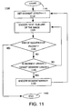
FIG. 11 illustrates a flowchart that summarizes the present data partitioning method 1100 (for one packet) that can be executed in a general purpose computer as described below.Method 1100 starts instep 1105 and proceeds to step 1110 where a counter for counting the current segment length (i.e., the predefined length in the packet where a segment marker will be inserted) is set to zero. - In
step 1120, a "sub-unit" of the image is encoded into the packet. In the above example, a sub-unit is defined to be a line of pixels of the image. A sub-unit is defined as a logical coding sub-unit of a texture unit that is being encoded into the packet and serves as a distinguishable location or distinctive point for the decoder to search for the segment marker. However, since texture units can be defined in a number of different manners, the present invention also presents below a number of sub-units having different defined structures. - In
step 1130,method 1100 queries whether the end of a sequence or a packet has been reached. If the query is affirmatively answered, thenmethod 1100 ends instep 1160. If the query is negatively answered, thenmethod 1100 proceeds to step 1140. - In
step 1140,method 1100 queries whether the segment length count is greater or equal to a threshold, target segment length. For example, the target segment length is set according to the bandwidth at which the current image is being coded. If the query is affirmatively answered, thenmethod 1100 proceeds to step 1150 where a symbol representative of a segment marker is coded into the packet. After a segment marker is encoded instep 1150,method 1100 returns to step 1110 where the segment length counter is again reset to zero. If the query is negatively answered, thenmethod 1100 returns to step 1120 and encodes a next sub-unit. The steps ofFIG. 11 are repeated until the end of a sequence or packet is reached. - Pseudo codes for coding a sequence or packet of the present invention are now provided for both perspectives, encoder and decoder. It is suggested that the reader applies the flowchart of
FIG. 11 to comprehend these pseudo codes. -
 Segment_length=0;
 While (not end of sequence or packet){
       If (Segment_length<target_segment_length)
              Encode one sub-unit in the sequence;
       Else{
              Encode a segment_marker with entropy coding
              Segment_length=0;
       }
       }
 Segment_length=0;
 While (not end of sequence or packet){
 If (Segment_length<target_segment_length)
              decode one sub-unit in the sequence;
              Else{
              Segment_length=0;
              If(decode a segment_marker correctly)
                     Continue;
              Else{
                    Zero out the coefficients after the last
                    correctly decoded segment_marker;
                    go to next packet;
              }
       }
       }

where the shaded area is representative of one tree block. Namely, condition "a" of equation (2) for defining a sub-unit is illustrated by sub-units 510a, 520a and 530a. Condition "b" of equation (2) for defining a sub-unit is illustrated by

Claims (7)
- A method for packetizing a bitstream, where said bitstream carries an entropy encoded image, said method comprising the steps of:a) generating a packet header;b) generating a payload comprising a plurality of payload segments with each payload segment having at least one sub-unit comprising hierarchical subband decomposed coefficients of said entropy encoded image; andc) inserting a coded segment marker after each of said plurality of payload segments.
- The method of claim 1, wherein said inserting step comprises the step of inserting a coded segment marker after said at least one sub-unit and only after a predefined number of bits have been exceeded.
- The method of claim 2, wherein said generating step (b) generates a payload segment having at least one sub-unit that is defined in accordance with a tree-depth scanning order of said entropy encoded image.
- The method of claim 2, wherein said generating step (b) generates a payload segment having at least one sub-unit that is defined in accordance with a layer-by-layer scanning order of said entropy encoded image.
- The method of claim 2, wherein said generating step (b) generates a payload segment having at least one sub-unit that is defined in accordance with a band-by-band scanning order of said entropy encoded image.
- A data structure (400) stored on a computer readable medium comprising:a packet header (410);a payload, coupled to said packet header, where said payload comprises a plurality of payload segments with each payload segment having at least one sub-unit comprising hierarchical subband decomposed coefficients of an entropy encoded image; anda plurality of segment markers (425) with one of said plurality of segment markers being coupled after one of said payload segments.
- A computer-readable medium (1014,1020) having stored thereon a plurality of instructions, the plurality of instructions including instructions which, when executed by a processor, cause the processor to perform the method of claim 1.
Applications Claiming Priority (5)
| Application Number | Priority Date | Filing Date | Title |
|---|---|---|---|
| US377385 | 1995-01-23 | ||
| US10308198P | 1998-10-05 | 1998-10-05 | |
| US103081P | 1998-10-05 | ||
| US09/377,385 US6553147B2 (en) | 1998-10-05 | 1999-08-19 | Apparatus and method for data partitioning to improving error resilience |
| PCT/US1999/023254 WO2000021299A2 (en) | 1998-10-05 | 1999-10-05 | Apparatus and method for data partitioning to improve error resilience |
Publications (2)
| Publication Number | Publication Date |
|---|---|
| EP1119977A2 EP1119977A2 (en) | 2001-08-01 |
| EP1119977B1 true EP1119977B1 (en) | 2013-05-22 |
Family
ID=26800072
Family Applications (1)
| Application Number | Title | Priority Date | Filing Date |
|---|---|---|---|
| EP99950216.4A Expired - Lifetime EP1119977B1 (en) | 1998-10-05 | 1999-10-05 | Apparatus and method for data partitioning to improve error resilience |
Country Status (4)
| Country | Link |
|---|---|
| EP (1) | EP1119977B1 (en) |
| JP (1) | JP2002527960A (en) |
| AU (1) | AU6292299A (en) |
| WO (1) | WO2000021299A2 (en) |
Families Citing this family (1)
| Publication number | Priority date | Publication date | Assignee | Title |
|---|---|---|---|---|
| KR100397511B1 (en) | 2001-11-21 | 2003-09-13 | 한국전자통신연구원 | The processing system and it's method for the stereoscopic/multiview Video |
Family Cites Families (9)
| Publication number | Priority date | Publication date | Assignee | Title |
|---|---|---|---|---|
| DE69127967D1 (en) * | 1991-07-11 | 1997-11-20 | Ibm | Improved method for subband image coding and device for carrying out this method |
| GB2281465B (en) * | 1993-08-27 | 1997-06-04 | Sony Uk Ltd | Image data compression |
| GB2295936B (en) * | 1994-12-05 | 1997-02-05 | Microsoft Corp | Progressive image transmission using discrete wavelet transforms |
| JPH09182085A (en) * | 1995-10-26 | 1997-07-11 | Sony Corp | Image encoding device, image decoding device, image encoding method, image decoding method, image transmitting method and recording medium |
| JPH09261644A (en) * | 1996-03-22 | 1997-10-03 | Matsushita Electric Ind Co Ltd | Wavelet video encoding method |
| JPH1174868A (en) * | 1996-09-02 | 1999-03-16 | Toshiba Corp | Information transmission method, coder/decoder in information transmission system adopting the method, coding multiplexer/decoding inverse multiplexer |
| EP0861001B1 (en) * | 1997-02-07 | 2012-05-23 | Texas Instruments Incorporated | Error resilient video encoding |
| EP0914004A1 (en) * | 1997-10-29 | 1999-05-06 | Ntec Media GmbH | Coding system and method for lossless and lossy compression of still and motion images |
| EP0944263A1 (en) * | 1998-03-20 | 1999-09-22 | Texas Instruments Incorporated | Image compression |
-
1999
- 1999-10-05 WO PCT/US1999/023254 patent/WO2000021299A2/en active Application Filing
- 1999-10-05 JP JP2000575309A patent/JP2002527960A/en active Pending
- 1999-10-05 EP EP99950216.4A patent/EP1119977B1/en not_active Expired - Lifetime
- 1999-10-05 AU AU62922/99A patent/AU6292299A/en not_active Abandoned
Also Published As
| Publication number | Publication date |
|---|---|
| EP1119977A2 (en) | 2001-08-01 |
| AU6292299A (en) | 2000-04-26 |
| WO2000021299A2 (en) | 2000-04-13 |
| WO2000021299A3 (en) | 2000-11-16 |
| JP2002527960A (en) | 2002-08-27 |
Similar Documents
| Publication | Publication Date | Title |
|---|---|---|
| US6553147B2 (en) | Apparatus and method for data partitioning to improving error resilience | |
| US6137915A (en) | Apparatus and method for error concealment for hierarchical subband coding and decoding | |
| US6487319B1 (en) | Apparatus and method for identifying the location of a coding unit | |
| US6526175B2 (en) | Apparatus and method for packetizing significance-based information | |
| US7606434B2 (en) | Apparatus and method for forming a coding unit | |
| US20030206557A1 (en) | Error-resilient video transmission system for wireless LAN utilizing data partitioning and unequal error protection | |
| US20110050935A1 (en) | Method and system for mixed-resolution low-complexity information coding and a corresponding method and system for decoding coded information | |
| US20040086041A1 (en) | System and method for advanced data partitioning for robust video transmission | |
| US7580582B2 (en) | Methods for decoding corrupt JPEG2000 codestreams | |
| EP1119977B1 (en) | Apparatus and method for data partitioning to improve error resilience | |
| EP0944263A1 (en) | Image compression | |
| Bilgin et al. | Decompression of corrupt JPEG2000 codestreams | |
| EP1118218A1 (en) | Apparatus and method for forming a coding unit | |
| Yuan | Wavelet video coding with application in network streaming | |
| EP1830574A2 (en) | Video compression using resynchronization words between sequences of symbols | |
| RONG | Context-based bit plane golomb coder for scalable image coding | |
| Hu | Significance map exploitation for bit rate reduction and error resilience improvement |
Legal Events
| Date | Code | Title | Description |
|---|---|---|---|
| PUAI | Public reference made under article 153(3) epc to a published international application that has entered the european phase |
Free format text: ORIGINAL CODE: 0009012 |
|
| 17P | Request for examination filed |
Effective date: 20010411 |
|
| AK | Designated contracting states |
Kind code of ref document: A2 Designated state(s): AT BE CH CY DE DK ES FI FR GB GR IE IT LI LU MC NL PT SE |
|
| RIN1 | Information on inventor provided before grant (corrected) |
Inventor name: SODAGAR, IRAJ Inventor name: CHAI, BING-BING |
|
| RBV | Designated contracting states (corrected) |
Designated state(s): DE FR GB NL |
|
| RAP1 | Party data changed (applicant data changed or rights of an application transferred) |
Owner name: MEDIATEK INC. |
|
| RAP1 | Party data changed (applicant data changed or rights of an application transferred) |
Owner name: SHARP KABUSHIKI KAISHA Owner name: MEDIATEK INC. |
|
| 17Q | First examination report despatched |
Effective date: 20070509 |
|
| GRAP | Despatch of communication of intention to grant a patent |
Free format text: ORIGINAL CODE: EPIDOSNIGR1 |
|
| RIC1 | Information provided on ipc code assigned before grant |
Ipc: H04N 21/2368 20110101ALI20121113BHEP Ipc: H04N 21/434 20110101ALI20121113BHEP Ipc: H04N 7/26 20060101AFI20121113BHEP |
|
| GRAS | Grant fee paid |
Free format text: ORIGINAL CODE: EPIDOSNIGR3 |
|
| GRAA | (expected) grant |
Free format text: ORIGINAL CODE: 0009210 |
|
| AK | Designated contracting states |
Kind code of ref document: B1 Designated state(s): DE FR GB NL |
|
| REG | Reference to a national code |
Ref country code: GB Ref legal event code: FG4D |
|
| REG | Reference to a national code |
Ref country code: DE Ref legal event code: R096 Ref document number: 69944755 Country of ref document: DE Effective date: 20130711 |
|
| REG | Reference to a national code |
Ref country code: NL Ref legal event code: VDEP Effective date: 20130522 |
|
| PG25 | Lapsed in a contracting state [announced via postgrant information from national office to epo] |
Ref country code: NL Free format text: LAPSE BECAUSE OF FAILURE TO SUBMIT A TRANSLATION OF THE DESCRIPTION OR TO PAY THE FEE WITHIN THE PRESCRIBED TIME-LIMIT Effective date: 20130522 |
|
| PLBE | No opposition filed within time limit |
Free format text: ORIGINAL CODE: 0009261 |
|
| STAA | Information on the status of an ep patent application or granted ep patent |
Free format text: STATUS: NO OPPOSITION FILED WITHIN TIME LIMIT |
|
| 26N | No opposition filed |
Effective date: 20140225 |
|
| REG | Reference to a national code |
Ref country code: DE Ref legal event code: R097 Ref document number: 69944755 Country of ref document: DE Effective date: 20140225 |
|
| REG | Reference to a national code |
Ref country code: FR Ref legal event code: PLFP Year of fee payment: 17 |
|
| REG | Reference to a national code |
Ref country code: FR Ref legal event code: PLFP Year of fee payment: 18 |
|
| REG | Reference to a national code |
Ref country code: FR Ref legal event code: PLFP Year of fee payment: 19 |
|
| REG | Reference to a national code |
Ref country code: FR Ref legal event code: PLFP Year of fee payment: 20 |
|
| PGFP | Annual fee paid to national office [announced via postgrant information from national office to epo] |
Ref country code: DE Payment date: 20181029 Year of fee payment: 20 |
|
| PGFP | Annual fee paid to national office [announced via postgrant information from national office to epo] |
Ref country code: GB Payment date: 20181029 Year of fee payment: 20 Ref country code: FR Payment date: 20181025 Year of fee payment: 20 |
|
| REG | Reference to a national code |
Ref country code: DE Ref legal event code: R071 Ref document number: 69944755 Country of ref document: DE |
|
| REG | Reference to a national code |
Ref country code: GB Ref legal event code: PE20 Expiry date: 20191004 |
|
| PG25 | Lapsed in a contracting state [announced via postgrant information from national office to epo] |
Ref country code: GB Free format text: LAPSE BECAUSE OF EXPIRATION OF PROTECTION Effective date: 20191004 |