EP1119977B1 - Vorrichtung und verfahren der datenunterteilung zur verbesserung der fehlerresistenz - Google Patents
Vorrichtung und verfahren der datenunterteilung zur verbesserung der fehlerresistenz Download PDFInfo
- Publication number
- EP1119977B1 EP1119977B1 EP99950216.4A EP99950216A EP1119977B1 EP 1119977 B1 EP1119977 B1 EP 1119977B1 EP 99950216 A EP99950216 A EP 99950216A EP 1119977 B1 EP1119977 B1 EP 1119977B1
- Authority
- EP
- European Patent Office
- Prior art keywords
- segment
- sub
- unit
- packet
- payload
- Prior art date
- Legal status (The legal status is an assumption and is not a legal conclusion. Google has not performed a legal analysis and makes no representation as to the accuracy of the status listed.)
- Expired - Lifetime
Links
Images


Classifications
-
- H—ELECTRICITY
- H04—ELECTRIC COMMUNICATION TECHNIQUE
- H04N—PICTORIAL COMMUNICATION, e.g. TELEVISION
- H04N19/00—Methods or arrangements for coding, decoding, compressing or decompressing digital video signals
- H04N19/65—Methods or arrangements for coding, decoding, compressing or decompressing digital video signals using error resilience
- H04N19/68—Methods or arrangements for coding, decoding, compressing or decompressing digital video signals using error resilience involving the insertion of resynchronisation markers into the bitstream
-
- H—ELECTRICITY
- H04—ELECTRIC COMMUNICATION TECHNIQUE
- H04N—PICTORIAL COMMUNICATION, e.g. TELEVISION
- H04N19/00—Methods or arrangements for coding, decoding, compressing or decompressing digital video signals
- H04N19/10—Methods or arrangements for coding, decoding, compressing or decompressing digital video signals using adaptive coding
- H04N19/169—Methods or arrangements for coding, decoding, compressing or decompressing digital video signals using adaptive coding characterised by the coding unit, i.e. the structural portion or semantic portion of the video signal being the object or the subject of the adaptive coding
- H04N19/186—Methods or arrangements for coding, decoding, compressing or decompressing digital video signals using adaptive coding characterised by the coding unit, i.e. the structural portion or semantic portion of the video signal being the object or the subject of the adaptive coding the unit being a colour or a chrominance component
-
- H—ELECTRICITY
- H04—ELECTRIC COMMUNICATION TECHNIQUE
- H04N—PICTORIAL COMMUNICATION, e.g. TELEVISION
- H04N19/00—Methods or arrangements for coding, decoding, compressing or decompressing digital video signals
- H04N19/60—Methods or arrangements for coding, decoding, compressing or decompressing digital video signals using transform coding
- H04N19/61—Methods or arrangements for coding, decoding, compressing or decompressing digital video signals using transform coding in combination with predictive coding
-
- H—ELECTRICITY
- H04—ELECTRIC COMMUNICATION TECHNIQUE
- H04N—PICTORIAL COMMUNICATION, e.g. TELEVISION
- H04N19/00—Methods or arrangements for coding, decoding, compressing or decompressing digital video signals
- H04N19/60—Methods or arrangements for coding, decoding, compressing or decompressing digital video signals using transform coding
- H04N19/63—Methods or arrangements for coding, decoding, compressing or decompressing digital video signals using transform coding using sub-band based transform, e.g. wavelets
- H04N19/64—Methods or arrangements for coding, decoding, compressing or decompressing digital video signals using transform coding using sub-band based transform, e.g. wavelets characterised by ordering of coefficients or of bits for transmission
- H04N19/645—Methods or arrangements for coding, decoding, compressing or decompressing digital video signals using transform coding using sub-band based transform, e.g. wavelets characterised by ordering of coefficients or of bits for transmission by grouping of coefficients into blocks after the transform
-
- H—ELECTRICITY
- H04—ELECTRIC COMMUNICATION TECHNIQUE
- H04N—PICTORIAL COMMUNICATION, e.g. TELEVISION
- H04N19/00—Methods or arrangements for coding, decoding, compressing or decompressing digital video signals
- H04N19/60—Methods or arrangements for coding, decoding, compressing or decompressing digital video signals using transform coding
- H04N19/63—Methods or arrangements for coding, decoding, compressing or decompressing digital video signals using transform coding using sub-band based transform, e.g. wavelets
- H04N19/64—Methods or arrangements for coding, decoding, compressing or decompressing digital video signals using transform coding using sub-band based transform, e.g. wavelets characterised by ordering of coefficients or of bits for transmission
- H04N19/647—Methods or arrangements for coding, decoding, compressing or decompressing digital video signals using transform coding using sub-band based transform, e.g. wavelets characterised by ordering of coefficients or of bits for transmission using significance based coding, e.g. Embedded Zerotrees of Wavelets [EZW] or Set Partitioning in Hierarchical Trees [SPIHT]
-
- H—ELECTRICITY
- H04—ELECTRIC COMMUNICATION TECHNIQUE
- H04N—PICTORIAL COMMUNICATION, e.g. TELEVISION
- H04N19/00—Methods or arrangements for coding, decoding, compressing or decompressing digital video signals
- H04N19/65—Methods or arrangements for coding, decoding, compressing or decompressing digital video signals using error resilience
- H04N19/66—Methods or arrangements for coding, decoding, compressing or decompressing digital video signals using error resilience involving data partitioning, i.e. separation of data into packets or partitions according to importance
-
- H—ELECTRICITY
- H04—ELECTRIC COMMUNICATION TECHNIQUE
- H04N—PICTORIAL COMMUNICATION, e.g. TELEVISION
- H04N19/00—Methods or arrangements for coding, decoding, compressing or decompressing digital video signals
- H04N19/70—Methods or arrangements for coding, decoding, compressing or decompressing digital video signals characterised by syntax aspects related to video coding, e.g. related to compression standards
-
- H—ELECTRICITY
- H04—ELECTRIC COMMUNICATION TECHNIQUE
- H04N—PICTORIAL COMMUNICATION, e.g. TELEVISION
- H04N19/00—Methods or arrangements for coding, decoding, compressing or decompressing digital video signals
- H04N19/10—Methods or arrangements for coding, decoding, compressing or decompressing digital video signals using adaptive coding
- H04N19/102—Methods or arrangements for coding, decoding, compressing or decompressing digital video signals using adaptive coding characterised by the element, parameter or selection affected or controlled by the adaptive coding
- H04N19/13—Adaptive entropy coding, e.g. adaptive variable length coding [AVLC] or context adaptive binary arithmetic coding [CABAC]
-
- H—ELECTRICITY
- H04—ELECTRIC COMMUNICATION TECHNIQUE
- H04N—PICTORIAL COMMUNICATION, e.g. TELEVISION
- H04N19/00—Methods or arrangements for coding, decoding, compressing or decompressing digital video signals
- H04N19/65—Methods or arrangements for coding, decoding, compressing or decompressing digital video signals using error resilience
-
- H—ELECTRICITY
- H04—ELECTRIC COMMUNICATION TECHNIQUE
- H04N—PICTORIAL COMMUNICATION, e.g. TELEVISION
- H04N19/00—Methods or arrangements for coding, decoding, compressing or decompressing digital video signals
- H04N19/85—Methods or arrangements for coding, decoding, compressing or decompressing digital video signals using pre-processing or post-processing specially adapted for video compression
- H04N19/89—Methods or arrangements for coding, decoding, compressing or decompressing digital video signals using pre-processing or post-processing specially adapted for video compression involving methods or arrangements for detection of transmission errors at the decoder
Definitions
- the invention relates to data partitioning in the field of digital multimedia communications. More particularly, the invention relates to a data partitioning method that improves error resilience, e.g., when applied to the entropy coding/decoding of hierarchical subband decomposed coefficients, e.g., wavelet transform coefficients.
- a packet is a group of binary digits that include data and control elements which are switched and transmitted as a composite whole.
- the data, control elements and other information are arranged in various specific formats.
- MPEG defines a packet as consisting of a header followed by a number of contiguous bytes (payload) from an "elementary data stream".
- An elementary stream is simply a generic term for one of the coded video, coded audio or other coded bitstreams.
- an MPEG-2 "transport stream" packet comprises a header, which may be four (4) or more bytes long with a payload having a maximum length of 184 bytes.
- Transport stream packets are part of one or more programs that are assembled into a transport stream. The transport stream is then transmitted over a channel with a particular transfer rate.
- transmission of packets over a noisy communication channel may cause corruption in the packets received by a receiver/decoder.
- some data streams or bitstreams carry compressed data that are correlated in a manner such that partial loss of a packet may cause the receiver/decoder to discard the entire packet.
- compression methods are useful for representing information as accurately as possible with a minimum number of bits and thus minimizing the amount of data that must be stored or transmitted.
- some compression methods employ "significance-based" information, e.g., a significance map-value model, to indicate to a receiver/decoder the significance of the transmitted information or absence of transmitted information.
- the "significance-based" information is often previously defined, e.g., using symbols, such that the receiver/decoder is able to decipher additional information from the transmitted information.
- the loss of compressed data such as "significance-based” information often results in substantial errors when a receiver/decoder attempts to decompress or decode the corrupted data.
- VLC variable-length coder
- the entire packet is often discarded, since one characteristics of an arithmetic encoder/decoding system is that every decoded symbol is treated as a valid symbol. Since errors are often detected from other symptoms, e.g., misalignment of the packets and so on, the decoder is often unable to distinguish where the error lies in the corrupted packet.
- a compression technique involves the transformation of an input image into transform coefficients using hierarchical subband decomposition.
- a useful compression technique appears in the Proceedings of the International Conference on Acoustics, Speech and Signal Processing, San Francisco, Cal. March 1992, volume IV, pages 657-660 , where there is disclosed a signal compression system which applies a hierarchical subband decomposition, or wavelet transform, followed by the hierarchical successive approximation entropy-coded quantizer.
- a wavelet pyramid also known as critically sampled quadrature-mirror filter (QMF) subband representation, is a specific type of multiresolution hierarchical subband representation of an image.
- QMF quadrature-mirror filter
- every coefficient at a given scale can be related to a set of coefficients at the next finer scale of similar orientation according to a structure called a wavelet tree.
- the coefficients at the coarsest scale will be called the parent nodes, and all coefficients corresponding to the same spatial or temporal location at the next finer scale of similar orientation will be called child nodes.
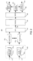
- a typical method of coding these transform coefficients is in "tree depth scan order as shown in FIG. 1 , where an image is decomposed into three levels of resolution.
- the wavelet coefficients are coded in tree blocks fashion, where each tree block is represented by three separate “texture units” shown with different shadings.
- Each texture unit is representative of a tree structure starting from the lowest or coarsest AC band to the highest or finest AC band coefficients.
- one or more texture units may be corrupted or lost when transmitted over a noisy channel.
- the loss of these texture units or texture packets often results in noticeable errors in the decoded image.
- an apparatus and a method for partitioning data to improve error resilience e.g., in a coding/decoding system that employs entropy coding. : Specifically, one or more segment markers (symbols) are entropy encoded along with the bitstream (payload) into a packet.
- segment marker is encoded into the packet at an approximate interval that is defined to be greater than or equal to the target segment length.
- the placement of the segment marker into the packet is also limited to being located at a juncture between two encoded "sub-units".
- a sub-unit is defined as a logical coding sub-unit of a texture unit that is being encoded into the packet. Since texture units can be defined in a number of different manners, the present invention also presents a number of sub-units having different defined structures.
- One advantage in such limiting of the placement of a segment marker to be between sub-units is that it provides an easily identifiable point for the decoder to start searching for the segment marker.
- the decoder can now readily determine if a current packet is corrupted. Namely, if the decoder is able to decode an uncorrupted segment marker as anticipated in the packet, then all the bits up to the point of the segment marker are considered also to be uncorrupted.
- the present invention provides several advantages. First, the use of an encoded segment marker reduces the amount of overhead, i.e., shorter code word, when compared to other packet markers such as adding additional Resynch markers. Second, no extra information is needed in the packet header to communicate the existence of the segment marker. Third, reinitialization of the entropy encoder is not required.
- FIG. 2 depicts a block diagram of a simplified structure of a packet stream system 200 of the present invention.
- a data stream such as a "transport stream” as defined in accordance with the MPEG standards is used in the packet stream system illustrated in FIG. 2 .
- transport stream as defined in accordance with the MPEG standards
- FIG. 2 depicts a data stream
- the present invention is described below using the transport stream as an example, those skilled in the art will realize that the present invention can be applied to any packet streams, e.g., an MPEG "program stream” or any other packet streams in accordance with other formats.
- the present invention is described below using the term "stream”, it should be understood that the various operations described below may be performed on the entire stream or portion thereof.
- System 200 includes an image/video encoder 220 for receiving and encoding video data 210 into an elementary video bitstream.
- the video encoder 220 is an encoder capable of generating hierarchical subband decomposed coefficients, e.g., wavelet coefficients with or without significance-based information.
- the image/video encoder 220 may be a single image encoder, e.g., a Joint Photographic Experts Group (JPEG) encoder, GIF, PICT, and the like, or an encoder for an image sequence (video), e.g., a block-based or wavelet-based image encoder operating in accordance with an MPEG standard.
- JPEG Joint Photographic Experts Group
- video e.g., a block-based or wavelet-based image encoder operating in accordance with an MPEG standard.
- image sequence, images, and video are used interchangeably.
- the invention operates in cooperation with any form of image or image sequence encoder that would benefit from the present packet structures to provide error resilience.
- VLBR Very Low Bit Rate
- the system may include an audio encoder 222 for receiving and encoding audio data 212 into an elementary audio bitstream.
- an audio encoder 222 for receiving and encoding audio data 212 into an elementary audio bitstream.
- a plurality of image/video encoders 220 n and audio encoders 222 n can be employed to produce a plurality of elementary bitstreams.
- the plurality of video and audio encoders can be collectively represented by a server 225, which may employ various encoders and/or may simply contain a plurality (or a library) of stored elementary streams in various storage media.
- the output of such server contains interleaved program streams.
- bitstreams are sent to packetizers 230 of the present invention, where the elementary bitstreams are converted into packets.
- Information for using the packets independently of the transport stream may be added when the packets are formed.
- non-audio/video data are allowed, but they are not shown in FIG. 2 .
- the present encoder and the packetizer are implemented in a single module, those skilled in the art will realize that the functions performed by the encoder and the packetizer can be jointly or separately implemented as required by a particular application.
- the packets are received and multiplexed by the transport stream multiplexer 240 to produce a transport stream 245.
- Packets constructed from elementary streams that form a program (a group of "Packet Identifiers" (PIDs) with associated video and audio data) generally share a common time base.
- the transport stream may contain one or more programs with one or more independent time bases, where the time bases are used for synchronized presentation.
- the time bases of different programs within a transport stream may be different.
- the transport stream 245 is transmitted over a transmission channel 250, which may further incorporate separate channel specific encoder and decoder (not shown).
- the transport stream 245 is demultiplexed and decoded by a transport stream demultiplexor 260, where the elementary streams serve as inputs to video decoder 270 and audio decoder 290, whose outputs are decoded video signals 275 and audio signals 295, respectively.
- timing information is also extracted by the transport stream demultiplexor 260 and delivered to clock control 280 for synchronizing the video and audio decoders with each other and with the channel. Synchronization of the decoders with the channel is accomplished through the use of the "Program Clock Reference” (PCR) in the transport stream.
- PCR Program Clock Reference
- the PCR is a time stamp encoding the timing of the bitstream itself and is used to derive the decoder timing.
- the packetizer 230 organizes the bitstream from the encoder into packets for transmission. If the transmission channel 250 is noisy, the transmitted packets can be corrupted or partially lost.
- the present invention describes a method below for manipulating a bitstream to form a particular packet structure within a packetizer 230, it should be understood that this operation can also be performed within the encoder 220 itself. As such, the implementation of the present invention is a matter of designer choice.
- Hierarchical subband decomposition provides a multi-resolution representation of an image. For example, the image is first decomposed into four subbands, LL, LH, HL, HH, each representing approximately a quarter of the entire frequency band. To obtain the next coarser scale image representation, the LL band is further divided into four subbands. The process can be repeated to form a hierarchical subband pyramid. It should be understood that hierarchical subband decomposition can apply any number of subband decompositions. Hierarchical subband decomposed coefficients can be packetized into units called "texture packets" for error resilience.
- a texture packet consists of one or more coding units, named "texture units”. Namely, if the texture unit is packetized into a single packet, then the packet is referred to as a texture packet. Examples of various texture unit structures are disclosed in US patent application entitled “Apparatus And Method For Forming A Coding Unit” with attorney docket 13151, which is herein incorporated by reference and is filed simultaneously herewith.
- FIG. 3 depicts a block diagram of a packet structure 300 having a header 310 and a payload 320 carrying a bitstream that is representative of coded data, e.g., entropy coded hierarchical subband decomposed coefficients.
- the header carries a Resynch marker that allows a decoder to synchronize the decoding process with the incoming packets, e.g., the start of a new packet.
- the addition of resynchronization markers at the beginning of each sequence (in JPEG terminology) or packet allows the resynchronization of the decoding process at the next Resynch marker if an error is encountered.
- FIG. 3 also illustrates an error 330 located somewhere within the payload of the packet that may have been caused by a noisy channel.
- the location and, at times, the existence of the error often goes undetected until the entire packet is decoded.
- the decoder is often unable to locate and correct the error due to the nature of entropy encoding and is forced to discard the entire payload 320 of the packet 300. For example, all the coefficient values are set to zero in the erroneous sequence or packet. The decoder must then rely on various error concealment methods to replace the missing data in the discarded payload.
- FIG. 9 an example of an efficient context-based entropy encoding method used in encoder 220 is illustrated in FIG. 9 . Namely, context modeling is used to determine the probability model that is used to entropy code each coefficient.
- FIG. 9
- Model_no f ⁇ i - 1 , j - 1 + f ⁇ i - 1 , j * 2 + f ⁇ i , j - 1 * 4
- f x y ⁇ 1 , if coeff x y is available and nonzero 0 , else Namely, the new context model is premised on its three neighbors shown as "o", 920-940. It should be noted that a total of eight (8) context models can be formed based on the significance of these three neighbors in accordance with equation 1 and the order of the three neighbors in accordance to equation (1) can be interchanged as desired.
- FIG. 9 illustrates one example of the correlation that is employed in an entropy coder.
- This complex correlation is the source of the present criticality where if a portion of a packet is corrupted, then the entire packet is often discarded since it is very difficult to ascertain the exact nature of the error and the location of the error in the packet.
- FIG. 4 now depicts a block diagram of a packet structure 400 having a header 410 and a plurality of payload segments 420a-420b (herein referred to as "segments") carrying a bitstream that is representative of coded data, e.g., entropy coded hierarchical subband decomposed coefficients.
- the payload segments 420a-420b are separated by segment markers 425 of the present invention.
- the error 430 is now disposed between two segment markers 425.
- the error may occur within a segment that is between a header and a segment marker or a segment marker and an end of packet marker or a header for the next packet (not shown).
- the present invention codes an extra symbol (representative of the segment marker) whenever a segment of the bitstream in a packet exceeds a "predefined length" and is at a "distinguishable location" in the encoded image.
- An example of the predefined length is approximately 512 bits. It should be noted that this predefined length can be modified in accordance with a particular application or a particular packet format.
- an error 430 can be identified with respect to its location if an anticipated segment marker is not present at the "predefined length" and at a predetermined location within the encoded image. For example, if the error 430 is detected, then the decoder can then only discard the payload segment 420b up to the segment marker 425, thereby retaining payload segment 420a. This ability to retain even a small portion of the payload of a packet will greatly improve the error resilience of an encoding/decoding system.
- the extra symbol can be a symbol that is different from any other possible symbols or it can be a symbol in an existing symbol set that is being used by the encoder that is generating the bitstream.
- the segment marker can be selected as having a certain bit pattern, e.g., "0101". Nevertheless, the extra symbol is entropy encoded in the same manner as other symbols that are encoded to form the payload of the packet. Generally, if a symbol is chosen from an existing symbol set, it is preferable to select a rarely occurring symbol to represent the segment marker.
- the bitstream length can be checked at the end of each line of the image. i.e., a "distinguishable location" in the encoded image. If at the end of the i th line, the bitstream length exceeds "N" bits, and the end of a texture unit has not been reached (i.e., not at the end of a packet), then a symbol representative of a segment marker is encoded into the bitstream. Normal coding resumes and the process is repeated throughout the coding process until the end of the packet is reached. The calculation of the bitstream length for each segment starts from a Resynch marker of a packet or after the encoding of the symbol representative of the segment marker.
- the present invention provides several advantages. First, the use of an encoded segment marker reduces the amount of overhead, i.e., shorter code word, when compared to other packet markers such as adding additional Resynch markers. Second, no extra information is needed in the packet header to communicate the existence of the segment marker. Third, reinitialization of the entropy encoder is not required.
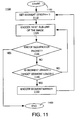
- FIG. 11 illustrates a flowchart that summarizes the present data partitioning method 1100 (for one packet) that can be executed in a general purpose computer as described below.
- Method 1100 starts in step 1105 and proceeds to step 1110 where a counter for counting the current segment length (i.e., the predefined length in the packet where a segment marker will be inserted) is set to zero.
- a counter for counting the current segment length i.e., the predefined length in the packet where a segment marker will be inserted
- a "sub-unit" of the image is encoded into the packet.
- a sub-unit is defined to be a line of pixels of the image.
- a sub-unit is defined as a logical coding sub-unit of a texture unit that is being encoded into the packet and serves as a distinguishable location or distinctive point for the decoder to search for the segment marker.
- texture units can be defined in a number of different manners, the present invention also presents below a number of sub-units having different defined structures.
- step 1130 method 1100 queries whether the end of a sequence or a packet has been reached. If the query is affirmatively answered, then method 1100 ends in step 1160. If the query is negatively answered, then method 1100 proceeds to step 1140.
- step 1140 method 1100 queries whether the segment length count is greater or equal to a threshold, target segment length. For example, the target segment length is set according to the bandwidth at which the current image is being coded. If the query is affirmatively answered, then method 1100 proceeds to step 1150 where a symbol representative of a segment marker is coded into the packet. After a segment marker is encoded in step 1150, method 1100 returns to step 1110 where the segment length counter is again reset to zero. If the query is negatively answered, then method 1100 returns to step 1120 and encodes a next sub-unit. The steps of FIG. 11 are repeated until the end of a sequence or packet is reached.
- a threshold target segment length
- Pseudo codes for coding a sequence or packet of the present invention are now provided for both perspectives, encoder and decoder. It is suggested that the reader applies the flowchart of FIG. 11 to comprehend these pseudo codes.
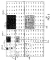
- FIG. 5 is a schematic illustration of the structure of a sub-unit for a texture unit that is defined in accordance with a tree-depth scanning order.
- the texture unit consists of the bitstream generated when encoding one tree structure. Namely, since a sub-unit is defined as a part or portion of a texture unit, as the texture unit formation is altered, the structure of the sub-unit must also be redefined accordingly.
- condition "a” of equation (2) for defining a sub-unit is illustrated by sub-units 510a, 520a and 530a.
- Condition "b” of equation (2) for defining a sub-unit is illustrated by sub-units 510b, 520b and 530b, where 1 is 2, i.e., a 4 x 4 block of coefficients constitutes a sub-unit.
- Condition "c” of equation (2) for defining a sub-unit is not illustrated, but sets each sub-unit to be no greater than a 16 x 16 block of coefficients for all decomposition level greater than three (3).
- FIGs. 6 and 7 are schematic illustrations of the structure of a sub-unit for a texture unit that is defined in accordance with a layer-by-layer scanning order.
- the pixels are coded by decomposition or wavelet levels, i.e., all coefficients for all subbands within a decomposition level are coded first prior to coding subbands of a next decomposition level.
- the sub-unit can be defined in two ways.
- a sub-unit is defined as comprising a block of coefficients from each subband corresponding to the same decomposition level, as shown in three separate shade areas 610, 620, and 630. Each shade represents one sub-unit.
- a sub-unit is the union of three 2 l x2 l blocks from the three subbands representing the same spatial location.
- a sub-unit is defined as comprising a row of coefficients from each subband corresponding to the same decomposition level, as shown in three separate shade areas 710, 720, and 730. Each shade represents one sub-unit.
- a sub-unit is the union of l rows from each of the three subbands.
- the texture unit in layer-by-layer scanning mode, consists of the bitstream generated when encoding a slice or portion of a slice of subband coefficients from all three subbands in the same wavelet decomposition layer. It should be noted that a slice can correspond to one or more rows in a subband. The subbands are scanned using the same scanning order to encode the coefficients.
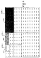
- FIG. 8 is a schematic illustration of the structure of a sub-unit for a texture unit that is defined in accordance with a band-by-band scanning order.
- the texture unit consists of the bitstream generated when encoding a slice of subband coefficients (2 l ) from one subband.
- the sub-unit is one or more rows of coefficients in a subband.
- a sub-unit can be defined as comprising a block of 2 l rows in a subband at l th level, as shown in three separate shade areas 810, 820, and 830.
- FIG. 10 illustrates a block diagram of an encoding system 1000 and a decoding system 1060 of the present invention.
- the encoding system 1000 comprises a general purpose computer 1010 and various input/output devices 1020.
- the general purpose computer comprises a central processing unit (CPU) 1012, a memory 1014 and an encoder/packetizer 1016 for encoding and packetizing an image, video and/or audio signal.
- CPU central processing unit
- memory 1014 for encoding and packetizing an image, video and/or audio signal.
- the encoder/packetizer 1016 is simply the video encoder 220, the audio encoder 222 and/or the packetizer 230 as discussed above in FIG. 2 . It should be understood that the encoders and the packetizer can be implemented jointly or separately.
- the encoder/packetizer 1016 can be physical devices, which are coupled to the CPU 1012 through a communication channel.
- the encoder/packetizer 1016 can be represented by a software application (or a combination of software and hardware, e.g., using application specific integrated circuits (ASIC)), where the software is loaded from a storage medium, (e.g., a magnetic or optical drive or diskette) and operated by the CPU in the memory 1014 of the computer.
- ASIC application specific integrated circuits
- the encoder/packetizer 1016 of the present invention can be stored on a computer readable medium.
- the computer 1010 can be coupled to a plurality of input and output devices 1020, such as a keyboard, a mouse, an audio recorder, a camera, a camcorder, a video monitor, any number of imaging devices or storage devices, including but not limited to, a tape drive, a floppy drive, a hard disk drive or a compact disk drive.
- input and output devices 1020 such as a keyboard, a mouse, an audio recorder, a camera, a camcorder, a video monitor, any number of imaging devices or storage devices, including but not limited to, a tape drive, a floppy drive, a hard disk drive or a compact disk drive.
- the encoding system is coupled to the decoding system via a communication channel 1050.
- the present invention is not limited to any particular type of communication channel.
- the decoding system 1060 comprises a general purpose computer 1070 and various input/output devices 1080.
- the general purpose computer comprises a central processing unit (CPU) 1072, a memory 1074 and an decoder/depacketizer 1076 for receiving and decoding a sequence of encoded images.
- the decoder/depacketizer 1076 is simply any decoders that are complementary to the encoder/packetizer 1016 as discussed above for decoding the bitstreams generated by the encoder/packetizer 1016 and for implementing the error concealment method as described above.
- the decoder 1076 can be a physical device, which is coupled to the CPU 1072 through a communication channel.
- the decoder/depacketizer 1076 can be represented by a software application which is loaded from a storage device, e.g., a magnetic or optical disk, and resides in the memory 1074 of the computer.
- any of complementary decoders of the encoder/packetizer 1016 of the present invention can be stored on a computer readable medium.
- the computer 1060 can be coupled to a plurality of input and output devices 1080, such as a keyboard, a mouse, a video monitor, or any number of devices for storing or distributing images, including but not limited to, a tape drive, a floppy drive, a hard disk drive or a compact disk drive.
- the input devices serve to allow the computer for storing and distributing the sequence of decoded video images.
Landscapes
- Engineering & Computer Science (AREA)
- Multimedia (AREA)
- Signal Processing (AREA)
- Compression Or Coding Systems Of Tv Signals (AREA)
- Detection And Prevention Of Errors In Transmission (AREA)
Claims (7)
- Verfahren zum Paketieren eines Bitstroms, wobei der Bitstrom ein entropiecodiertes Bild führt, wobei das Verfahren die folgenden Schritte umfasst:a) Erzeugen eines Paket-Headers;b) Erzeugen von Nutzinformationen, die eine Vielzahl von Nutzinformationssegmenten umfassen, wobei jedes Nutzinformationssegment mindestens eine Subeinheit aufweist, die hierarchische Subband-zerlegte Koeffizienten des entropiecodierten Bildes umfasst; undc) Einfügen einer codierten Segmentmarkierung nach jedem der Vielzahl von Nutzinformationssegmenten.
- Verfahren nach Anspruch 1, wobei der Einfügeschritt den Schritt des Einfügens einer codierten Segmentmarkierung nach der mindestens einen Subeinheit und erst, nachdem eine vordefinierten Anzahl von Bit überstiegen wurde, umfasst.
- Verfahren nach Anspruch 2, wobei der Erzeugungsschritt (b) ein Nutzinformationssegment erzeugt, das mindestens eine Subeinheit aufweist, die gemäß einer Baumtiefe-Scanning-Reihenfolge des entropiecodierten Bildes definiert ist.
- Verfahren nach Anspruch 2, wobei der Erzeugungsschritt (b) ein Nutzinformationssegment erzeugt, das mindestens eine Subeinheit aufweist, die gemäß einer schichtenweisen Scanning-Reihenfolge des entropiecodierten Bildes definiert ist.
- Verfahren nach Anspruch 2, wobei der Erzeugungsschritt (b) ein Nutzinformationssegment erzeugt, das mindestens eine Subeinheit aufweist, die gemäß einer bandweisen Scanning-Reihenfolge des entropiecodierten Bildes definiert ist.
- Datenstruktur (400), die auf einem computerlesbaren Medium gespeichert ist, umfassend:einen Paket-Header (410);Nutzinformationen, die mit dem Paket-Header gekoppelt sind, wobei die Nutzinformationen eine Vielzahl von Nutzinformationssegmenten umfassen, wobei jedes Nutzinformationssegment mindestens eine Subeinheit aufweist, die hierarchische Subband-zerlegte Koeffizienten eines entropiecodierten Bildes umfasst; undeine Vielzahl von Segmentmarkierungen (425), wobei eine der Vielzahl von Segmentmarkierungen nach einem der Nutzinformationssegmente gekoppelt wird.
- Computerlesbares Medium (1014, 1020), auf dem eine Vielzahl von Anweisungen gespeichert ist, wobei die Vielzahl von Anweisungen Anweisungen umfasst, die, wenn sie durch einen Prozessor ausgeführt werden, bewirken, dass der Prozessor das Verfahren nach Anspruch 1 ausführt.
Applications Claiming Priority (5)
| Application Number | Priority Date | Filing Date | Title |
|---|---|---|---|
| US377385 | 1995-01-23 | ||
| US10308198P | 1998-10-05 | 1998-10-05 | |
| US103081P | 1998-10-05 | ||
| US09/377,385 US6553147B2 (en) | 1998-10-05 | 1999-08-19 | Apparatus and method for data partitioning to improving error resilience |
| PCT/US1999/023254 WO2000021299A2 (en) | 1998-10-05 | 1999-10-05 | Apparatus and method for data partitioning to improve error resilience |
Publications (2)
| Publication Number | Publication Date |
|---|---|
| EP1119977A2 EP1119977A2 (de) | 2001-08-01 |
| EP1119977B1 true EP1119977B1 (de) | 2013-05-22 |
Family
ID=26800072
Family Applications (1)
| Application Number | Title | Priority Date | Filing Date |
|---|---|---|---|
| EP99950216.4A Expired - Lifetime EP1119977B1 (de) | 1998-10-05 | 1999-10-05 | Vorrichtung und verfahren der datenunterteilung zur verbesserung der fehlerresistenz |
Country Status (4)
| Country | Link |
|---|---|
| EP (1) | EP1119977B1 (de) |
| JP (1) | JP2002527960A (de) |
| AU (1) | AU6292299A (de) |
| WO (1) | WO2000021299A2 (de) |
Families Citing this family (1)
| Publication number | Priority date | Publication date | Assignee | Title |
|---|---|---|---|---|
| KR100397511B1 (ko) | 2001-11-21 | 2003-09-13 | 한국전자통신연구원 | 양안식/다시점 3차원 동영상 처리 시스템 및 그 방법 |
Family Cites Families (9)
| Publication number | Priority date | Publication date | Assignee | Title |
|---|---|---|---|---|
| EP0522219B1 (de) * | 1991-07-11 | 1997-10-15 | International Business Machines Corporation | Verbessertes Verfahren zur Teilbandbildkodierung und Einrichtung zur Durchführung dieses Verfahrens |
| GB2281465B (en) * | 1993-08-27 | 1997-06-04 | Sony Uk Ltd | Image data compression |
| GB2295936B (en) * | 1994-12-05 | 1997-02-05 | Microsoft Corp | Progressive image transmission using discrete wavelet transforms |
| JPH09182085A (ja) * | 1995-10-26 | 1997-07-11 | Sony Corp | 画像符号化装置、画像復号装置、画像符号化方法、画像復号方法、画像伝送方法及び記録媒体 |
| JPH09261644A (ja) * | 1996-03-22 | 1997-10-03 | Matsushita Electric Ind Co Ltd | ウエーブレットビデオ符号化方法 |
| JPH1174868A (ja) * | 1996-09-02 | 1999-03-16 | Toshiba Corp | 情報伝送方法およびその方法が適用される情報伝送システムにおける符号化装置/復号化装置、並びに符号化・多重化装置/復号化・逆多重化装置 |
| EP0861001B1 (de) * | 1997-02-07 | 2012-05-23 | Texas Instruments Incorporated | Fehler resistente Videocodierung |
| EP0914004A1 (de) * | 1997-10-29 | 1999-05-06 | Ntec Media GmbH | Codierungssystem und -verfahren zur verlustfreien und verlustbehafteten Kompression von stehenden und bewegten Bildern |
| EP0944263A1 (de) * | 1998-03-20 | 1999-09-22 | Texas Instruments Incorporated | Bildkompression |
-
1999
- 1999-10-05 AU AU62922/99A patent/AU6292299A/en not_active Abandoned
- 1999-10-05 EP EP99950216.4A patent/EP1119977B1/de not_active Expired - Lifetime
- 1999-10-05 WO PCT/US1999/023254 patent/WO2000021299A2/en active Application Filing
- 1999-10-05 JP JP2000575309A patent/JP2002527960A/ja active Pending
Also Published As
| Publication number | Publication date |
|---|---|
| AU6292299A (en) | 2000-04-26 |
| WO2000021299A3 (en) | 2000-11-16 |
| WO2000021299A2 (en) | 2000-04-13 |
| EP1119977A2 (de) | 2001-08-01 |
| JP2002527960A (ja) | 2002-08-27 |
Similar Documents
| Publication | Publication Date | Title |
|---|---|---|
| US6553147B2 (en) | Apparatus and method for data partitioning to improving error resilience | |
| US6137915A (en) | Apparatus and method for error concealment for hierarchical subband coding and decoding | |
| US6487319B1 (en) | Apparatus and method for identifying the location of a coding unit | |
| US6526175B2 (en) | Apparatus and method for packetizing significance-based information | |
| US7606434B2 (en) | Apparatus and method for forming a coding unit | |
| US20030206557A1 (en) | Error-resilient video transmission system for wireless LAN utilizing data partitioning and unequal error protection | |
| US20110050935A1 (en) | Method and system for mixed-resolution low-complexity information coding and a corresponding method and system for decoding coded information | |
| US20040086041A1 (en) | System and method for advanced data partitioning for robust video transmission | |
| US7580582B2 (en) | Methods for decoding corrupt JPEG2000 codestreams | |
| EP1119977B1 (de) | Vorrichtung und verfahren der datenunterteilung zur verbesserung der fehlerresistenz | |
| EP0944263A1 (de) | Bildkompression | |
| Bilgin et al. | Decompression of corrupt JPEG2000 codestreams | |
| EP1118218A1 (de) | Geraet und verfahren zur bildung einer kodiereinheit | |
| Yuan | Wavelet video coding with application in network streaming | |
| EP1830574A2 (de) | Videokompression unter Verwendung von Resynchronisationswörtern zwischen Sequenzen von Symbolen | |
| RONG | Context-based bit plane golomb coder for scalable image coding | |
| Hu | Significance map exploitation for bit rate reduction and error resilience improvement |
Legal Events
| Date | Code | Title | Description |
|---|---|---|---|
| PUAI | Public reference made under article 153(3) epc to a published international application that has entered the european phase |
Free format text: ORIGINAL CODE: 0009012 |
|
| 17P | Request for examination filed |
Effective date: 20010411 |
|
| AK | Designated contracting states |
Kind code of ref document: A2 Designated state(s): AT BE CH CY DE DK ES FI FR GB GR IE IT LI LU MC NL PT SE |
|
| RIN1 | Information on inventor provided before grant (corrected) |
Inventor name: SODAGAR, IRAJ Inventor name: CHAI, BING-BING |
|
| RBV | Designated contracting states (corrected) |
Designated state(s): DE FR GB NL |
|
| RAP1 | Party data changed (applicant data changed or rights of an application transferred) |
Owner name: MEDIATEK INC. |
|
| RAP1 | Party data changed (applicant data changed or rights of an application transferred) |
Owner name: SHARP KABUSHIKI KAISHA Owner name: MEDIATEK INC. |
|
| 17Q | First examination report despatched |
Effective date: 20070509 |
|
| GRAP | Despatch of communication of intention to grant a patent |
Free format text: ORIGINAL CODE: EPIDOSNIGR1 |
|
| RIC1 | Information provided on ipc code assigned before grant |
Ipc: H04N 21/2368 20110101ALI20121113BHEP Ipc: H04N 21/434 20110101ALI20121113BHEP Ipc: H04N 7/26 20060101AFI20121113BHEP |
|
| GRAS | Grant fee paid |
Free format text: ORIGINAL CODE: EPIDOSNIGR3 |
|
| GRAA | (expected) grant |
Free format text: ORIGINAL CODE: 0009210 |
|
| AK | Designated contracting states |
Kind code of ref document: B1 Designated state(s): DE FR GB NL |
|
| REG | Reference to a national code |
Ref country code: GB Ref legal event code: FG4D |
|
| REG | Reference to a national code |
Ref country code: DE Ref legal event code: R096 Ref document number: 69944755 Country of ref document: DE Effective date: 20130711 |
|
| REG | Reference to a national code |
Ref country code: NL Ref legal event code: VDEP Effective date: 20130522 |
|
| PG25 | Lapsed in a contracting state [announced via postgrant information from national office to epo] |
Ref country code: NL Free format text: LAPSE BECAUSE OF FAILURE TO SUBMIT A TRANSLATION OF THE DESCRIPTION OR TO PAY THE FEE WITHIN THE PRESCRIBED TIME-LIMIT Effective date: 20130522 |
|
| PLBE | No opposition filed within time limit |
Free format text: ORIGINAL CODE: 0009261 |
|
| STAA | Information on the status of an ep patent application or granted ep patent |
Free format text: STATUS: NO OPPOSITION FILED WITHIN TIME LIMIT |
|
| 26N | No opposition filed |
Effective date: 20140225 |
|
| REG | Reference to a national code |
Ref country code: DE Ref legal event code: R097 Ref document number: 69944755 Country of ref document: DE Effective date: 20140225 |
|
| REG | Reference to a national code |
Ref country code: FR Ref legal event code: PLFP Year of fee payment: 17 |
|
| REG | Reference to a national code |
Ref country code: FR Ref legal event code: PLFP Year of fee payment: 18 |
|
| REG | Reference to a national code |
Ref country code: FR Ref legal event code: PLFP Year of fee payment: 19 |
|
| REG | Reference to a national code |
Ref country code: FR Ref legal event code: PLFP Year of fee payment: 20 |
|
| PGFP | Annual fee paid to national office [announced via postgrant information from national office to epo] |
Ref country code: DE Payment date: 20181029 Year of fee payment: 20 |
|
| PGFP | Annual fee paid to national office [announced via postgrant information from national office to epo] |
Ref country code: GB Payment date: 20181029 Year of fee payment: 20 Ref country code: FR Payment date: 20181025 Year of fee payment: 20 |
|
| REG | Reference to a national code |
Ref country code: DE Ref legal event code: R071 Ref document number: 69944755 Country of ref document: DE |
|
| REG | Reference to a national code |
Ref country code: GB Ref legal event code: PE20 Expiry date: 20191004 |
|
| PG25 | Lapsed in a contracting state [announced via postgrant information from national office to epo] |
Ref country code: GB Free format text: LAPSE BECAUSE OF EXPIRATION OF PROTECTION Effective date: 20191004 |