EP1119798B1 - Method and apparatus for simultaneous amplitude and quantitative phase contrast imaging by numerical reconstruction of digital holograms - Google Patents
Method and apparatus for simultaneous amplitude and quantitative phase contrast imaging by numerical reconstruction of digital holograms Download PDFInfo
- Publication number
- EP1119798B1 EP1119798B1 EP99945836A EP99945836A EP1119798B1 EP 1119798 B1 EP1119798 B1 EP 1119798B1 EP 99945836 A EP99945836 A EP 99945836A EP 99945836 A EP99945836 A EP 99945836A EP 1119798 B1 EP1119798 B1 EP 1119798B1
- Authority
- EP
- European Patent Office
- Prior art keywords
- hologram
- digital
- specimen
- reference wave
- reconstruction
- Prior art date
- Legal status (The legal status is an assumption and is not a legal conclusion. Google has not performed a legal analysis and makes no representation as to the accuracy of the status listed.)
- Expired - Lifetime
Links
Images


Classifications
-
- G—PHYSICS
- G03—PHOTOGRAPHY; CINEMATOGRAPHY; ANALOGOUS TECHNIQUES USING WAVES OTHER THAN OPTICAL WAVES; ELECTROGRAPHY; HOLOGRAPHY
- G03H—HOLOGRAPHIC PROCESSES OR APPARATUS
- G03H1/00—Holographic processes or apparatus using light, infrared or ultraviolet waves for obtaining holograms or for obtaining an image from them; Details peculiar thereto
- G03H1/04—Processes or apparatus for producing holograms
- G03H1/0443—Digital holography, i.e. recording holograms with digital recording means
-
- G—PHYSICS
- G03—PHOTOGRAPHY; CINEMATOGRAPHY; ANALOGOUS TECHNIQUES USING WAVES OTHER THAN OPTICAL WAVES; ELECTROGRAPHY; HOLOGRAPHY
- G03H—HOLOGRAPHIC PROCESSES OR APPARATUS
- G03H1/00—Holographic processes or apparatus using light, infrared or ultraviolet waves for obtaining holograms or for obtaining an image from them; Details peculiar thereto
- G03H1/04—Processes or apparatus for producing holograms
- G03H1/08—Synthesising holograms, i.e. holograms synthesized from objects or objects from holograms
- G03H1/0866—Digital holographic imaging, i.e. synthesizing holobjects from holograms
-
- G—PHYSICS
- G03—PHOTOGRAPHY; CINEMATOGRAPHY; ANALOGOUS TECHNIQUES USING WAVES OTHER THAN OPTICAL WAVES; ELECTROGRAPHY; HOLOGRAPHY
- G03H—HOLOGRAPHIC PROCESSES OR APPARATUS
- G03H1/00—Holographic processes or apparatus using light, infrared or ultraviolet waves for obtaining holograms or for obtaining an image from them; Details peculiar thereto
- G03H1/0005—Adaptation of holography to specific applications
- G03H2001/005—Adaptation of holography to specific applications in microscopy, e.g. digital holographic microscope [DHM]
-
- G—PHYSICS
- G03—PHOTOGRAPHY; CINEMATOGRAPHY; ANALOGOUS TECHNIQUES USING WAVES OTHER THAN OPTICAL WAVES; ELECTROGRAPHY; HOLOGRAPHY
- G03H—HOLOGRAPHIC PROCESSES OR APPARATUS
- G03H1/00—Holographic processes or apparatus using light, infrared or ultraviolet waves for obtaining holograms or for obtaining an image from them; Details peculiar thereto
- G03H1/04—Processes or apparatus for producing holograms
- G03H1/0443—Digital holography, i.e. recording holograms with digital recording means
- G03H2001/0445—Off-axis recording arrangement
-
- G—PHYSICS
- G03—PHOTOGRAPHY; CINEMATOGRAPHY; ANALOGOUS TECHNIQUES USING WAVES OTHER THAN OPTICAL WAVES; ELECTROGRAPHY; HOLOGRAPHY
- G03H—HOLOGRAPHIC PROCESSES OR APPARATUS
- G03H2210/00—Object characteristics
- G03H2210/40—Synthetic representation, i.e. digital or optical object decomposition
- G03H2210/44—Digital representation
- G03H2210/441—Numerical processing applied to the object data other than numerical propagation
-
- G—PHYSICS
- G03—PHOTOGRAPHY; CINEMATOGRAPHY; ANALOGOUS TECHNIQUES USING WAVES OTHER THAN OPTICAL WAVES; ELECTROGRAPHY; HOLOGRAPHY
- G03H—HOLOGRAPHIC PROCESSES OR APPARATUS
- G03H2210/00—Object characteristics
- G03H2210/50—Nature of the object
- G03H2210/56—Multiple objects, e.g. each in different environment
-
- G—PHYSICS
- G03—PHOTOGRAPHY; CINEMATOGRAPHY; ANALOGOUS TECHNIQUES USING WAVES OTHER THAN OPTICAL WAVES; ELECTROGRAPHY; HOLOGRAPHY
- G03H—HOLOGRAPHIC PROCESSES OR APPARATUS
- G03H2226/00—Electro-optic or electronic components relating to digital holography
- G03H2226/11—Electro-optic recording means, e.g. CCD, pyroelectric sensors
Definitions
- the present invention relates to a method for simultaneous amplitude and quantitative phase contrast imaging by numerical reconstruction of digitally encoded holograms.
- the basic idea with the present invention is to record a hologram of the specimen and to reconstruct this hologram with a numerical method.
- This idea has been reported for the first time in 1967 by J.W. Goodman and R. W. Laurence , "Digital image formation from electronically detected holograms," Appl. Phys. Lett. 11, 77-79 (1967), who used a vidicon detector for the hologram recording, and in 1971 by M.A. Kronrod et al. "Reconstruction of a hologram with a computer," Soviet Phys.-Technical Phys. 17, 333-334 (1972), who used a digitized image of a hologram recorded on a photographic plate.
- the used reconstruction algorithm is the same as for amplitude contrast imaging and do not really allows phase contrast imaging, because, in this case, the reconstructed optical field is the product of the object wave by the complex conjugate of the reference wave (or the product of the complex conjugate of the object wave by the reference wave).
- this reconstruction algorithm can be used in holographic interferometry, because the subtraction between two reconstructed phase distributions obtained with the same reference wave provides an image which represents only the phase difference between the deformed and undeformed states of the object.
- phase contrast image has been reported in 1997 by E. Cuche et al. "Tomographie optique par une technique d'holographie despre en3.1 coherence," J. Opt. 28, 260-264 (1997), who have used a modified reconstruction algorithm including a multiplication of the digital hologram by a digital replica of the reference wave (digital reference wave).
- the phase contrast image has been obtained with a plane wave as reference and in direct observation, meaning that no magnification or demagnification optics is introduced along the optical path of the object wave.
- the present invention provides a straightforward link between phase contrast imaging and optical metrology.
- Quantitative phase contrast means that the phase contrast image is free of artifacts or aberrations and can be directly used for quantitative measurements of optical properties (e.g. refractive index) or structural informations (e.g. topography, thickness). More precisely, “quantitative phase contrast'' means here that the value of each pixel of the phase contrast image is equal, modulo 2 ⁇ , to the value of the phase of the object wave at the corresponding area of specimen.
- “Simultaneous amplitude and quantitative phase contrast” means that two images of the specimen can be reconstructed from the same hologram. One of these images with an amplitude contrast and the other one with a quantitative phase contrast. These images can be analyzed separately or compared the one with the other. Their information content (or the information content of several pairs of images reconstructed for different orientations of the specimen) can be associated in order to build a computed three-dimensional description of the specimen, for example a three-dimensional tomography of semi-transparent specimens. Spectroscopic measurements are also possible with the present invention by recording two or more holograms of the same specimen at different wavelengths. Such multi-wavelength procedure can also be useful for the precise determination of objects dimensions or refractive index in metrology.
- the advantage of our invention is that the recording of only one hologram is necessary while the recording of four or more interferograms is required with interference microscopy. Moreover, no displacement or moving of optical elements is needed with the present invention. As a consequence, the acquisition time is reduced providing a lower sensitivity to thermal and mechanical drifts. Robustness is a great assess of the present invention.
- phase aberrations are corrected digitally. Indeed, a microscope objective which is introduced in an interferometer produces a curvature of the wavefronts which affects the phase of the object wave. Therefore, for phase contrast imaging with the present invention or more generally in any interferometric system, this phase aberration function must be corrected.
- interference microscopy this problem is solved experimentally by inserting the same microscope objective in the reference arm, at equal distance from the exit of the interferometer. This arrangement called Linnick interferometer requires that if any change has to be made in the object arm, then the same change must be precisely reproduced in the reference arm in such a way that the interference occurs between similarly deformed wavefronts.
- the physical interpretation of amplitude and quantitative phase contrasts vary. If the hologram is recorded with the wave that is reflected by the specimen (reflection geometry), the amplitude contrast depends on variations of the reflectance at the specimen surface and the phase contrast depends on the topography of the specimen and/or on changes of the phase shift at the reflection. If the hologram is recorded with the wave that is transmitted by a transparent or semi-transparent specimen (transmission geometry), the amplitude contrast is related to changes in absorption and the phase contrast depends on variations of the thickness and/or of the refractive index (or more generally on variations of the optical path).
- phase contrast generally has more than one origin.
- the measurement of the refractive index of a transparent specimen requires the knowledge of the thickness and inversely the measurement of the thickness requires the knowledge of the refractive index.
- the analysis of the results must take into account the variation of the phase change on the reflection interface, if the complex index of refraction of the different materials is not the same. If a pure topographic or a pure refractive index or a pure thickness measurement is desired, known methods such as ellipsometry or multi-wavelength measurements could be used in combination with the present invention.
- refractive index measurement on a transparent specimen of unknown thickness can be performed by recording two or more holograms at different wavelengths. Assuming that the thickness of the specimen is constant for each hologram, variations of the reconstructed phase distributions are due to variations of the refractive index as a function of the wavelength. Using a model describing the variation of the refractive index as a function of the wavelength, the refractive index of the specimen or its thickness can be deduced from the quantitative phase contrast images. With a semi-transparent specimen (e.g.
- the hologram can be recorded, in the reflection geometry, with the light that is reflected by a selected slice inside the specimen.
- contrasts amplitude and phase
- both contrasts depend on the optical properties of the selected slice and on the optical properties of other volumes inside the specimen where the light has traveled before and after the reflection.
- the present invention provides a more general method for the numerical reconstruction of both amplitude and quantitative phase contrast images from a digital hologram.
- the numerical method for the hologram reconstruction comprises the calculation of a digital replica of the reference wave called digital reference wave.
- An array of complex numbers called digital phase mask is also calculated in order to correct the phase aberrations of the imaging system.
- the present invention provides unique results.
- the technique provides a quantitative phase contrast meaning that the reconstructed phase distribution can be directly used for applications in metrology, in particular for surface profilometry, refractive index measurements or more generally for quantitative material testing (shape and position measurements, surface roughness measurement, optical properties measurement).
- an amplitude contrast image of the specimen can be reconstructed from the same hologram. It is an important feature of the present invention that a three dimensional description of the specimen can be obtained digitally with only one image acquisition.
- the numerical reconstruction method performs a calculation which describes the propagation of the wavefront that would be diffracted by the hologram during a standard holographic reconstruction.
- the calculation consists in a numerical evaluation of the diffraction pattern which is produced in an observation plane when the hologram is illuminated by a replica of the reference wave.
- the scalar description of the diffraction is considered here and the reconstruction method consists in the numerical calculation of the Fresnel-Kirchhoff integral or of the Rayleigh-Sommerfeld integral.
- the diffraction calculation can be performed using an approximation of these integrals such as the Fraunhofer or the Fresnel integrals. In some cases such as Fourier holography, a simple Fourier transform calculation can be used.
- the configuration used for the hologram creation in particular the distance between the hologram and the specimen, will be adjusted in such a way to produce a Fresnel hologram for which the diffraction calculation can be performed in the Fresnel approximation.
- the advantage of the Fresnel approximation is that the computations are simple and can be performed very fast using a discrete formulation of the Fresnel integral expressed in terms of a Fourier transform.
- a wide range of experimental configurations are covered by the Fresnel approximation.
- image reconstruction in both amplitude and phase contrast requires the adjustment of several constants which are involved by the numerical reconstruction method.
- These constants are called reconstruction parameters and their values are defined by the experimental configuration.
- the reconstruction parameters can be divided into three categories: the reconstruction distance which is related to image focusing; the reference wave parameters which are related to the definition of the digital reference wave; and the phase aberration function correction parameters which are related to the definition of the digital phase mask. It is an object of the present invention to describe how these reconstruction parameters are defined and how their values must be adjusted. It is clear that the values of the reconstruction parameters are fixed for a given experimental configuration and that the same values of the reconstruction parameters can be used to reconstruct several holograms without new adjustment procedures if the experimental configuration is the same for these holograms.
- NHT Numerical Holographic Telescope
- NHS Numerical Holographic Microscope
- NHE Numerical Holographic Endoscope
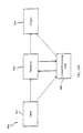
- FIG. 1 shows diagrammatically the different steps of the entire imaging procedure.
- the beam emitted by an illumination source 1 illuminates a set-up 2 which creates a hologram 4 of the specimen 3 .
- the set-up 2 collects the light from the illumination source 1 and provides illumination 1 of the specimen 3 .
- It includes also a device for creating a reference wave R and a device for creating an object wave O from the light that is transmitted or reflected or scattered by the specimen 3 .
- the object wave O and the reference wave R are combined in such a way that they interfere in a plane.
- the object wave will be understood as the part of the illumination wave which has been transmitted, reflected or more generally scattered by the object and captured by the optical system.
- the present invention is not restricted to the optical domain and can be applied for the numerical reconstruction of holograms recorded with any kind of electromagnetic (e.g. X-ray) or non-electromagnetic (e.g. acoustics or heat) waves. Photon density waves can also be used. For this reason, the nature, the wavelength and the coherence of the illumination source 1 are not specified here. Gas lasers, semiconductor lasers, solid state lasers, laser diodes, superluminescent diodes, narrow and broadband sources, white light sources, X-ray sources, and electron beam are examples of means which can be used as illumination source.
- electromagnetic e.g. X-ray
- non-electromagnetic e.g. acoustics or heat
- Photon density waves can also be used.
- the nature, the wavelength and the coherence of the illumination source 1 are not specified here.
- a combination of two or more illumination sources can also be used.
- two illumination sources of different wavelengths can be combined in order to create an illumination source with a so called synthetic wavelength.
- the set-up 2 is designed in such a way that the polarization of the reference wave R matches (as close as possible) the polarization of the object wave O .
- This closeness of the polarization of the object to that of the reference waves is important to optimise the interference between these two waves. If the object wave contains different kind of photons with different polarization states, as it happens for example when scattering events occur inside the specimen or when the birefringence of the specimen is not uniform, working with a fixed polarization of the reference wave allows one to select the photons of the object wave, the polarization of which is close to the polarization of the reference wave.
- the device which creates the object wave O includes magnifications optics or demagnification optics.
- magnification optics is to be understood as being a single lens or an assembly of lenses and/or optical fibers which produces a magnified image of the specimen with a better resolution than direct imaging.
- magnification optics producing an image of the specimen, the size of which is the same as the size of the specimen (magnification equal to unity), is also included here.
- ''demagnification optics is to be understood as being a single lens or an assembly of lenses and optical fibers which produces a smaller image of the specimen in order to allow imaging of larger specimens than direct imaging.
- the set-up 2 will be designed in order to produce an off-axis hologram.
- the term "off-axis hologram" is to be understood as meaning that the directions of propagation of the reference wave R and of the object wave O are not parallel, at their incidence on the plane where the hologram is created.
- the off-axis geometry advantageously permits to separate the zero order of diffraction, the real image and the twin image during the reconstruction.
- FIG. 2A presents one of the possible configurations with an angle ⁇ between the directions of the object wave and of the reference wave at their incidence on the hologram plane.
- the off-axis geometry may be restricted to small angles in order to avoid that the spatial frequency of the created interferogram exceeds the resolution power of recording media.
- the angle between the reference wave and the object wave, at their incidence on the plane where the hologram is created must not exceed a certain value for which the interference fringes of the hologram are not resolved by the image acquisition system.
- the off-axis geometry may even be considered at the limit of very small angles, but in this case, the zero order of diffraction may cover parts or integrality of the twin image or of the real image.
- additional methods can be used in order to suppress the zero order of diffraction. For example, a method proposed by T.M.
- this method can also be applied when the amplitude of the reference wave is not constant.
- Such a result can be obtained by subtracting a locally evaluated value of the zero order of diffraction (
- the digital hologram can be divided in small elements called submatrix of constant (or non-constant) sizes, and the method proposed by T.M. Kreis and W.P.O. Jüptner can be applied to each of these submatrix.
- the size and the number of the submatrix must be chosen in such a way to restore, with enough precision, the variations of the zero order of diffraction in the hologram plane. However the size of a submatrix must not be smaller than a minimum size for which a submatrix contains only one constructive and one destructive interference.
- Another aspect of the present invention is based on the application of a band-pass filter to the Fourier transform of the digital hologram, and which also allows for the complete elimination of the zero-order of diffraction
- This method is based on the fact that, in off-axis holography, the spatial frequencies corresponding the interfering terms ( R * O and RO * ) are higher than the spatial frequencies which correspond to the zero order of diffraction (
- a digital image processing method which comprises the steps of:
- a filtered digital hologram with a constant zero order is obtained.
- the value of the zero order is equal to the mean intensity calculated for the entire hologram area. Therefore, the zero order can be completely suppressed by subtracting the mean intensity to the intensity of each pixel of the filtered digital hologram.
- the application of the above mentioned Fourier filtering image processing is one of the possible digital image processing which can be optionally applied before and/or after the numerical reconstruction of the hologram.
- several digital image processing treatments can be applied in order to improve the signal to noise ratio or in order to enhance the fringes visibility of the digital hologram 7.
- the digital hologram can also be multiplied by a two-dimensional function (for example a Hanning or a Hamming or a Gaussian window) in order to perform data windowing.
- a two-dimensional function for example a Hanning or a Hamming or a Gaussian window
- This feature of a possible digital image processing treatment of the hologram is one of the advantage of the present invention in comparison with standard holographic methods which use, for example, photographic plates as recording media and which do not allow for such a straightforward processing of the hologram, before its reconstruction.
- a particularly interesting digital treatment consists in multiplying the hologram by a two dimensional real function which modifies the transmission (or the amplitude transmittance) of the hologram aperture in order to perform an apodization of this aperture.
- Aperture apodization is a well known technique in optics and is used to reduce diffraction effects (fluctuation of the diffracted field in amplitude and phase) arising when a beam of coherent light is truncated by an aperture.
- An apodized aperture is characterized by an amplitude transmittance (transmission) which does not change abruptly from zero to unity at the edge of the aperture, but in a smooth and continuous manner.
- Several kind of continuous functions can be used to define the transition of the transmission (from zero to unity) at the edge of the aperture: Gaussian, Super Gaussian, trigonometric or a combination of functions.
- a transmission function defined iteratively during an optimisation process can also be used.
- the transmission function of the apodized aperture is defined in such a way that a large region in the center of the aperture remains transparent.
- in-line or Gabor holograms can also be considered with the present invention.
- the present invention can be used in combination with other methods (image processing methods or experimental procedures) for the elimination of the zero order of diffraction and/or for the elimination of the twin or real image.
- image processing methods or experimental procedures image processing methods or experimental procedures
- a method which is similar to interference microscopy has been proposed by I. Yamaguchi and T. Zhang "Phase-shifting digital holography", Opt. Lett. 22, 1268-1270 (1997). This method requires the recording of four interferograms taken with phase shifts (of 90°) of the reference wave and allows the suppression of both the zero order of diffraction and the twin image.
- the object wave can be measured in amplitude and phase in the hologram plane.
- the present invention can then be used in order to recover the amplitude and the phase at the surface of the specimen.
- Piezo actuated mirrors, acousto-optics or electro-optics or photo-elastic modulators are example of optional optical elements which can be used to modulate or to shift the phase of the reference wave and/or of the object wave.
- said means which creates the reference wave R can comprise a device which modifies the wavelength of the reference wave with respect to the wavelength of the object wave.
- a similar device can also be inserted in said means which creates an object wave O.
- Acousto optic modulators, electro-optic modulators, photo-elastic modulators, piezo-electric driven mirrors are example of means which can be used to modulate the wavelength of the reference wave and/or of the object wave. These means are example of optional optical components featured in FIGS 2B, 2C, 2D. Physically distinct sources can also be used for the illumination and for the creation of the reference.
- the set-up 2 will be designed in order to produce a Fresnel hologram.
- the term "Fresnel hologram'' is to be understood as meaning that the hologram reconstruction can be performed by a calculation of scalar diffraction in the Fresnel approximation.
- the numerical calculation of the discrete Fresnel integral will be explained in details further.
- the advantage of the Fresnel approximation is that the computations are simple and can be performed very fast. In addition, a wide range of experimental configurations are covered by the Fresnel approximation.
- a simple Fourier transform calculation or a diffraction calculation in the Fraunhofer approximation can also be used.
- the set-up 2 will also comprise means which allow for the adjustment of the length of the path of the reference wave R .
- These means may be different or confounded with the means to form the reference wave: prisms, parallel plate, mirrors, gratings, optionally mounted on mechanical actuators of any kind: mechanical, magnetic actuator and piezo-electric translators. It may include also optional optical elements like optical modulators: piezoelectric modulator, acousto-optical modulators, elasto-optical modulators and phase modulators: electro-optical modulators, liquid crystals modulators.
- Such a device is an example of optical components featured in FIGS 2B, 2C, 2D.
- FIG. 2B, FIG. 2C and FIG. 2D present three possible realizations of the set-up 2.
- the set-up consists basically of a Michelson interferometer, or more generally a Twyman-Green interferometer, designed for imaging in the reflection geometry.
- the beam emitted by the illumination source is expanded in diameter and the interferometer comprises a microscope objective in the object arm and a mirror in the reference arm which reflects a plane wave as reference R . If the mirror is tilted. with two degrees of freedom, off-axis holograms can be recorded.
- the set-up consists basically of a Mach-Zender interferometer designed for imaging in the transmission geometry.
- the interferometer comprises two beam expanders in each arm of the interferometer.
- a configuration with only one beam expander located just after the illumination source can also be used.
- the beam expanders can include a pinhole for spatial filtering.
- a microscope objective collects the light that is transmitted by the specimen.
- a mirror which can be tilted reflects a plane wave as reference R.
- the set-up consists basically of a Mach-Zender interferometer designed for reflection imaging.
- a lens with a long focal length is inserted between the beam expander and the microscope objective. This lens acts as a condenser and its position is adjusted in order to illuminate the sample through the microscope objective with a collimated beam.
- This condenser is important for reflection imaging because, as explained later, in holographic microscopy the specimen can be located near the object focal plane of the microscope objective. If necessary, for example if a high intensity is desired for the object illumination, a condenser can also be inserted before the specimen in the transmission geometry presented in FIG. 2C. This condenser is an example of optical components featured in FIG. 2C. These examples of set-up are adequate for the creation of Fresnel off-axis holograms. Additional elements called optional optical elements (see FIGS. 2B, 2C, and 2D) can be introduced in both arms of the interferometer and/or before and/or after the beam splitters located at the entrance and/or at the exit of the interferometers.
- Neutral density filters, prisms, half-wave plates, quarter-wave plates, polarizing plates, Wollaston prisms, iris diaphragms, lenses, spatial filters, pinholes are examples of optional optical elements.
- a Wollaston prism inserted close to the recombination beam splitter, can be used to separate the reference wave onto two components with cross polarization and different directions of propagation (dotted line).
- Polarizing beam splitters can also be used instead of simple beam splitters.
- optional optical elements can be inserted along the paths of the reference wave and/or along the path of the object wave.
- modulators which modify the wavelength and/or the amplitude and/or the frequency and/or the polarization and/or the phase and/or the optical path length of the waves.
- Polarizers, half and quarter wave plates, Wollaston prisms, neutral density filters, acousto-optic modulators, liquid crystal devices, dielectric media, assembly of prisms and/ or mirrors are example of means which can be used as optional optical elements.
- FIG. 2B, 2C and 2D are just shown here as illustrations of possible examples.
- Most of the designs of interferometers can be used to form a digital holographic set-up.
- an assembly of optics components for example lenses, Hopkin relay optics and optical fibers
- the hologram can be recorded at the distal end of a rigid or flexible endoscope.
- the present invention includes a digital method for the correction of the associated aberrations.
- phase aberration functions is to be understood as being a deformation of the wavefronts which travel across a magnification or demagnification optics.
- the correction of the phase aberration functions compensate this wavefronts deformation and allows to recover the phase distribution of the original wavefronts.
- An image acquisition system 5 acquires an image of the hologram 4 (Fig.1). Any kind of existing or further developed image acquisition system or image sensor can be used. Because the numerical reconstruction method is fast, rapid or real-time acquisition systems such as video camera can be used. Charged Coupled Device (CCD) camera, intensified or cooled CCD, progressive scan CCD, line-scan camera, electron bombardment CCD (EB CCD) high resolution camera, integrating CCD, numerical or digital camera, CMOS image sensors, array of photodiodes, array of sensors, array of acoustic sensor, are examples of means which can be used as image acquisition system. Slower image acquisition systems which acquires an image of the hologram by scanning a sensor in a plane with a mechanical device can also be used. An image of the hologram can also be recorded on a photographic plate, on a photopolymer film or using an other photo-chemical process. A photorefractive crystal can also be used as image acquisition system.
- CCD Charged Coupled Device
- EB CCD electron bombardment
- an image digitizer 6 performs the digitalization (typically a framegrabber or more generally a device which performs an analog to digital conversion) of the acquired image of the hologram.
- the image resulting from the various means described previously is called a digital hologram 7 and is an array I H (k ⁇ x, l ⁇ y ) of N x x N y digitally encoded numbers which results from the two-dimensional spatial sampling of the hologram intensity I H (x,y).
- This two-dimensional spatial sampling can be performed by the image acquisition system and/or by the image digitizer.
- the image sensor is rectangular and the spatial sampling is regular (with constant sampling intervals).
- I H (k ⁇ x, l ⁇ y) can be expressed from I H (x,y) as follows: where ⁇ ( x,y ) is a two dimensional Dirac delta function, k,l are integers, L x ⁇ L y is the area of the acquired image of the hologram (the area of the sensitive surface of the image acquisition system), rect(x,y) is a function the value of which is 1 if the point of coordinates ( x,y ) is inside the acquired part of the hologram and 0 elsewhere. ⁇ x and ⁇ y are the sampling intervals along the 0x and 0y directions respectively.
- An amplitude contrast image 9 and a quantitative phase contrast image 10 of the specimen 3 are numerically reconstructed from the digital hologram 4 .
- the reconstruction method requires the adjustment of several reconstruction parameters 8 which define the geometry used for the hologram creation (specimen location, characteristics of the reference wave and of the magnification optics). The methods used for the numerical reconstruction of the hologram and the procedure for the adjustment of the reconstruction parameters will be explained in details further.
- the term ''reconstruction parameters" 8 is to be understood as being a set of constants which must be supplied to the program which executes the numerical reconstruction of the hologram. These constants can be supplied to the computer which executes the program by a human operator, by an apparatus which communicates with the computer or by an other program running on the same (or on an other) computer.
- the hologram can be recorded on a photographic plate and the hologram reconstruction is performed optically by illuminating the hologram with a replica of the reference wave R as shown in FIG. 3.
- the two first terms of Eq. (1.7) correspond to the zero order of diffraction, the third term to the twin image and the fourth term to the real image.
- Eq. (1.7) corresponds to the zero order of diffraction
- the third term to the twin image corresponds to the twin image.
- the fourth term to the real image corresponds to the real image.
- FIG. 3 if the hologram has been recorded in an off-axis geometry, these three terms can be observed separately in the observation plane 0 ⁇ .
- the virtual image appears as emitted by a replica of the specimen located at its initial position, while the real image is a converging term which is focused symmetrically with respect to the hologram.
- the zero order of diffraction corresponds to the part of the light that is not diffracted by the hologram and propagates along the direction of the reference wave. As shown in FIG.
- 0xy designates the coordinates of the hologram plane and 0 ⁇ the coordinates of the observation plane (the plane where the reconstruction of the hologram takes place).
- the numerical method for the hologram reconstruction simulates the standard optical reconstruction of a hologram.
- the optical reconstruction is performed by illuminating the hologram with the reference wave R and the transmitted wavefront (Eq. (1.7)) propagates from the hologram plane 0xy to an observation plane 0 ⁇ where the real image is focused.
- a digital transmitted wavefront ⁇ D (k ⁇ x,l ⁇ y) is computed by multiplication of the digital hologram I H (k ⁇ x , l ⁇ y ) by a digitally computed reference wave R D (k ⁇ x, l ⁇ y) called further the digital reference wave.
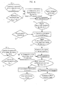
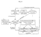
- FIG. 4 presents diagrammatically the steps of computations for the reconstruction of a digital hologram 7 .
- the terms “reference wave parameters” 13 , “reconstruction distance” 12 and “phase aberration function correction parameters” 14 are to be understood as being “reconstruction parameters” 8 (see FIG.1) as defined previously in this section.
- the entire procedure can be divided into seven steps:
- the digital reference wave is an array R D (k ⁇ x , l ⁇ y ) of complex numbers which is computed on the basis of an analytical expression of the reference wave f(x,y) 15 , the expression of which is defined by the geometrical and optical characteristics of the set-up.
- the analytical expression of the reference wave involves two sets of reference wave parameters ⁇ p amp ⁇ and ⁇ p ph ⁇ 13 which must be adjusted for a precise description of the wavefronts of the digital reference wave.
- f(x,y) is a two-dimensional complex function which is defined in such a way that the digital reference wave reproduces as well as possible the reference wave R which has been used to create the hologram.
- f(x,y) can be expressed as follows: where Amp(x,y, ⁇ p amp ⁇ ) and ph(x,y, ⁇ p ph ⁇ ) are real functions, which define respectively the amplitude and the phase of f(x,y).
- the digital reference wave can be computed using the following expression: where k x , k y and A R are the reference wave parameters. k x and k y are two real numbers which represent the components of the normalized wavevector (direction of propagation of the plane wave) and A R is real number which represents the amplitude of reference wave.
- the digital reference wave can be computed using the following expression: where ( x R , y R , z R ) are the coordinates of the point source with respect to the centre of the hologram plane 0xy and A R is the amplitude of spherical wave at the point source.
- Paraboloidal waves Gaussian beams or wavefront representation with Zernike polynomials are other examples of models which can be used for the calculation of the digital reference wave.
- the function which describes the amplitude of f ( x,y ) ( A(x,y) ) can also be measured by simply acquiring an image of the reference intensity in absence of interference with the object wave.
- the phase of the digital reference wave can also be measured using an interferometric method with a reference object (a mirror for example or a micro-bead in gold may also be used).
- the measured phase can be directly used to define the digital reference wave.
- the interferogram can also be analysed using a fringe analysis method or with a wavefront fitting method. For example the measured wavefront can be fitted with an expansion in Zernike polynomials in order to obtain a measured analytical expression of the reference wave.
- the reconstruction distance must be equal to the distance between the hologram and the magnified (or demagnified) image of the specimen.
- the calculation of scalar diffraction can be performed by a numerical calculation of the Fresnel-Kirchhoff or Rayleigh-Sommerfeld integrals or by numerical calculation of an approximation of these integrals.
- the Fresnel approximation can be used and will be described in details further.
- the result of this step is called the reconstructed wavefront in the observation plane ⁇ (m ⁇ ,n ⁇ ) 17 , where m,n are integers (- N x /2 ⁇ m ⁇ N x /2 and -N y /2 ⁇ n ⁇ N y /2) and ⁇ , ⁇ are the sampling intervals in the observation plane.
- This step and the next step e. are necessary with the optical set-up used for the hologram creation producing phase aberrations in the observation plane.
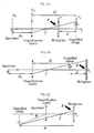
- a magnification optics or a demagnification optics is introduced along the optical path of the object wave. Examples of such a configuration are shown in FIGS. 6A to 6C with a magnification optics (M.O.), of focal length f , which produces a magnified image of the specimen.
- M.O. magnification optics
- FIG. 6A the image plane 0x 1 y i is located at a distance d i from the plane of the M.O.
- the specimen is located in the object plane 0 x o y o at a distance d o from the M.O. and the hologram plane 0xy is inserted between the M.O. and the magnified image at a distance d from the image plane.
- the presented examples of possible arrangements correspond to standard configurations for holographic microscopy: see: M. Pluta, Holographic Microscopy, in Advances in optical and electron microscopy Vol. 10, (Academic Press, London, 1987). In these cases, the created hologram is not a hologram of the object itself but that of the magnified image.
- the same symbol d designates the specimen-hologram distance in direct imaging (for example as presented in FIG. 2A) and the magnified (or demagnified) image-hologram distance in presence of magnification (or demagnification) optics (for example as presented in FIGS. 6A to 6C).
- the hologram is created (by interference with the reference wave R ) between the M.O. and the magnified image.
- the hologram is created behind the magnified image. It is also possible to create a hologram of a virtual (magnified as in FIG. 6C or demagnified) image of the specimen.
- a magnification (or demagnification) optics produces a phase aberration function in the image plane 0 x i y i .
- the optical field O i (x i ,y i ) in the image plane of a magnification or demagnification optics can be expressed as follow: where exp ⁇ i ⁇ ab (x i ,y i ) ⁇ is calculated from the phase aberration function ⁇ ab (x i ,y i ) function and where O C (x i ,y i ) is the "correct" or unaberrated optical field in the image plane which would correspond to an imaging system free of phase variations, including possibly aberrations.
- ⁇ ab (x i ,y i ) is called analytical expression of the phase aberration function 16 and will be used for the calculation of the phase mask.
- ⁇ ab (x i ,y i ) involves a set of reconstruction parameters ( 8 in FIG. 1) called phase aberration function correction parameters ⁇ p ab ⁇ 14.
- the analytical expression of the phase aberration function ⁇ ab (x i ,y i ) 16 and the number of elements in ⁇ p ab ⁇ depend on the shape, on the material and on the geometrical arrangement of the components of the magnification or demagnification optics. In most cases, the phase aberration functions depends also on the distance between the specimen and the magnification or demagnification optics (e.g. d o as defined in FIG. 6A).
- the reconstruction distance d R 12 is correctly adjusted (the real image or the twin image are in focus), when the observation plane 0 ⁇ matches the image plane 0 x i y i .
- the reconstructed wavefront ⁇ ( m ⁇ , n ⁇ ) 17 can be expressed as a function of a correct reconstructed wavefront ⁇ c ( m ⁇ , n ⁇ ) 18 in a way similar to that presented in Eq. (1.9).
- the analytical expression of the phase aberration function is defined in such a way that the digital phase mask represents as well as possible the complex conjugate of the phase aberration function function in the observation plan.
- a set of reconstruction parameters called phase aberration function correction parameters ⁇ p ab ⁇ 14 are involved by ⁇ ab ( ⁇ , ⁇ ) and allows a precise adjustment of the digital phase mask C (m ⁇ , n ⁇ ).
- the digital phase mask C ( m ⁇ , n ⁇ ) can be expressed as follows: where D is the phase aberration function correction parameter which depends on the specimen-lens distance d o and on the lens-magnified image distance d i (see e.g. FIG. 6A):
- the phase produced by a microscope objective are more complex and more sophisticated models can be used for the computation of the digital phase mask.
- the digital phase mask can be calculated on the basis of an expansion of the phase aberration function in Zernicke polynomials.
- the wavefront deformation which produces the phase aberration function can also be measured using an interferometric method with a reference object (for example a mirror).
- the measured phase can be directly used to define the digital phase mask.
- the interferogram can also be analysed using a fringe analysis method or with a wavefront fitting method.
- the measured wavefront deformation can be fitted with an expansion in Zernicke polynomials in order to obtain a measured analytical expression of the phase aberration function.
- the corrected reconstructed wavefront ⁇ C ( m ⁇ , n ⁇ ) 18 can be obtained by computing the multiplication between the reconstructed wavefront in the observation plane ⁇ ( m ⁇ , n ⁇ ) 17 and the digital phase mask C (m ⁇ , n ⁇ ): where m,n are integers and ⁇ , ⁇ are the sampling intervals in the observation plane.
- This multiplication performs a digital correction of the phase aberration function.
- This point is specific to the present invention, in comparison with other existing interferometric techniques for optical imaging, because usually, when optics components are introduced in one arm of an interferometer, the associated phase aberrations is optically compensated by the introduction of the same optics in the other arm of the interferometer (Linnik interferometer).
- the result is an array of real numbers which represents the amplitude contrast image 9 . If the modulus is calculated instead of the square modulus, an other amplitude contrast image can also be obtained. As shown in FIG. 1, digital image processing treatments can be optionally applied to the computed amplitude or intensity distribution in order to improve the quality of the amplitude contrast image.
- phase unwrapping techniques can be applied to the quantitative phase contrast image when the distribution of the optical phase associated to the specimen exceeds the [- ⁇ , ⁇ ] (or [0,2 ⁇ ] ) interval.
- digital image processing treatments can be optionally applied to the computed phase distribution in order to improve the quality of the quantitative phase contrast image. In this case, a particular attention must be paid to the fact that the applied digital image processing treatments do not affect the quantitative property of the reconstructed phase distribution.
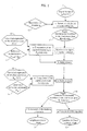
- the present invention relates also to a numerical method for the hologram reconstruction which contains the same steps of computations as presented in FIG. 4, but with a different order of execution.
- FIG. 5 presents an other possibility for the numerical reconstruction of a digital hologram 7.
- the numerical calculation of scalar diffraction (step c.) is directly applied to the digital hologram I H (k ⁇ x,l ⁇ y) 7 and the obtained result (reconstructed wavefront in the observation plane ⁇ (m ⁇ ,n ⁇ ) 17 is multiplied by a digital reference wave in the observation plane R D ( m ⁇ , n ⁇ ).
- the digital reference wave is computed according the recipe explained in step a .
- the reconstructed wavefront in the observation plane ⁇ ( m ⁇ , n ⁇ ) 17 contains a zero order of diffraction, a twin image and a real image which are located at different places of the observation plane (see FIG. 3).
- the steps of computations after the diffraction calculation do not necessarily have to be performed for the entire image but only for a selected region of interest (see FIGS. 4 and 5) which contains the twin image or the real image.
- digital image processing methods such as brightness and contrast adjustments, offset subtraction, band-pass filtering of the spatial frequencies in the Fourier plane, over or under-sampling of the digital hologram or other existing or further developed digital image processing methods can be optionally applied in order to improve the quality of the digital hologram 7 .
- digital image processing methods such as brightness and contrast adjustments, offset subtraction, band-pass filtering of the spatial frequencies in the Fourier plane, over or under-sampling of the digital hologram or other existing or further developed digital image processing methods can be optionally applied in order to improve the quality of the digital hologram 7 .
- Statistical calculations can also be applied to a set of acquired holograms.
- similar operations can also be optionally applied to the reconstructed images 9 and 10 .
- the spatial frequencies are distributed principally at three different locations.
- 2 are located in the center of the Fourier plane (low spatial frequencies) and the spatial frequencies corresponding to the interfering terms R*O and RO* (see Eq. (1.1), (1.2), (1.3),) are located at higher spatial frequencies, the position of which are related to the characteristics of the off-axis geometry.
- R*O and RO* see Eq. (1.1), (1.2), (1.3) are located at higher spatial frequencies, the position of which are related to the characteristics of the off-axis geometry.
- the off-axis holograms can be Fourier transformed and filtered in the Fourier domain in order to conserve only the spatial frequencies of the interfering terms. After the application of this filter, the hologram can be inverse Fourier transformed and numerically reconstructed.
- the numerical calculation of scalar diffraction can be performed using a discrete formulation of the Fresnel integral.
- ⁇ x and ⁇ y are the sampling intervals in the hologram plane as defined by Eqs. (1.5) and (1.6).
- d R is the reconstruction distance 12 .
- C (m ⁇ , n ⁇ ) is the digital phase mask and R D (k ⁇ x, l ⁇ y ) is the digital reference wave.
- Eq. (1.18) can also be considered as being the expression of a fast Fresnel transform.
- an other implementation of the method can be obtained by computing directly the scalar diffraction pattern of the digital hologram I H (k ⁇ x,l ⁇ y ) and by multiplying the obtained result by a digital reference wave in the observation plane.
- the reconstruction algorithm in the Fresnel approximation is given by:
- the reconstruction distance d R 12 represents the distance between the hologram plane 0xy and the observation plane 0 ⁇ .
- the adjustment of the value of d R allows to focus the reconstructed images.
- d R d , with d as defined in FIG. 2A and in FIG. 3).
- d R must fit the optical pathlength between the specimen and the hologram. It is understood that the optical path length is defined by the quotient between the real distance and the refractive index of the dielectric media.
- the adjustment of d R can be compared to the adjustment of the localisation in optical microscopy or in photography.
- optical microscopy the focalisation is performed by translating the specimen along the optical axis of the microscope.
- photography the specimen is fixed and the focalisation is performed by translating a lens along the optical axis of the imaging device.
- the same kind of operation can be performed digitally by adjusting the reconstruction distance d R .
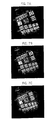
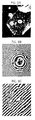
- FIG. 7 shows three amplitude contrast images of a USAF test target obtained with different values of the reconstruction distance and is presented here in order to illustrate the effect of digital focusing associated to the adjustment of d R .
- FIG. 7A has been obtained for a too small value of d R
- FIG. 7B for the correct value of d R
- FIG. 7C for a too large value.
- d R the sign of d R is important. If d R is positive the real image is in focus and if d R is negative, the observation plane is located behind the hologram and the twin image is in focus.
- the reference wave parameters 13 are two sets of reconstruction parameters; ⁇ p amp ⁇ for the definition of the amplitude and ⁇ p ph ⁇ for the definition of the phase of the digital reference wave.
- the number of elements in these sets depends on the analytical expression of the reference wave 15.
- a precise adjustment of the reference wave parameters which defines the phase of the digital reference wave ( ⁇ p ph ⁇ ) is important for quantitative phase contrast imaging. As explained above (see. Eq. (1.8) and related explications), the values of these parameters must be adjusted with precision in such a way that the wavefronts of the digital reference wave R D match as close as possible those of the experimental reference wave R (of those of its complex conjugate).
- the phase aberration function correction parameters 14 form a set of reconstruction parameters ⁇ p ab ⁇ .
- the number of element in this set depends on the analytical expression of the phase aberration function 16 .
- a precise adjustment of the phase aberration function parameters is important for quantitative phase contrast imaging.
- the values of these parameters must be adjusted with precision in such a way that the multiplication of the reconstructed wavefront in the observation plane ⁇ ( m ⁇ , n ⁇ ) by the digital phase mask C ( m ⁇ , n ⁇ ) corrects as well as possible the phase aberration functions in the observation plane.
- the same kind of considerations is applicable to known situations in classical microscopy or in photography where, for example, the degree of precision of the focalisations of an image is limited by the quality of the optics and by the criteria (sometimes subjective) used to evaluate this focalisation.
- the adjustment of the reconstruction parameters which influence the quantitative phase contrast image is performed using a an optically flat reference surface in and/or near or around the specimen.
- this optically flat reference surface is a polished metallic or dielectric surface or a test pattern on which the specimen lies, typically a glass plate used as specimen holder as in classical microscopy.
- the reconstruction parameters can be adjusted in order to obtain the predicted phase distribution in the corresponding area of the reconstructed quantitative phase contrast image.
- the reconstruction parameters will be adjusted in order to obtain a constant phase distribution if the reference surface is planar.
- FIG. 8A shows an example of reconstructed quantitative phase contrast image of a biological cell on a glass plate.
- the reconstruction parameters have been adjusted in order to obtain a constant phase distribution around the cell where only the glass plate which is flat and planar participate to the image formation.
- the case where the specimen is not lying on a dielectric plate or on a mirror, but isolated in free space (supported, suspended or floating) can naturally also be considered.
- FIG. 8 An illustration showing the effect a bad adjustment of the reference wave and phase aberration function correction parameters is shown in FIG. 8.
- a plane wave has been used for the hologram recording and a microscope objective has been used as magnification optics, with a geometrical arrangement as shown in FIG. 6A.
- the digital reference wave R D (k ⁇ x , l ⁇ y ) is computed using Eq. (1.8) with the reference wave parameters A R , k x and k y and the digital phase mask C (m ⁇ , n ⁇ ) ) is computed using Eqs. (1.10) and (1.11) with the phase aberration function correction parameter D .
- FIG. 8 An illustration showing the effect a bad adjustment of the reference wave and phase aberration function correction parameters is shown in FIG. 8.
- a plane wave has been used for the hologram recording and a microscope objective has been used as magnification optics, with a geometrical arrangement as shown in FIG. 6A.
- the digital reference wave R D (k ⁇
- FIG. 8A shows the obtained quantitative phase contrast image with a correct adjustment of all reconstruction parameters ( d R , D, k x , k y and A R .).
- the cell membrane, the nucleus and some intracellular structures are observable in this image.
- the value of the phase aberration function correction parameter D is modified with respect to its correct value, the obtained quantitative phase contrast image which is shown in FIG. 8B.
- curved concentric fringes which are characteristic of the quadratic phase aberration function of the microscope objective, appear on the image.
- the reference wave is spherical (or nearly spherical)
- a bad adjustment of the reference wave parameters will produce curved fringes on the phase contrast image and the reference wave parameters are adjusted in order to eliminate these fringes.
- a finer adjustment of the reconstruction parameters is performed in order to suppress residual constant curvatures of the reconstructed phase distribution.
- a first numerical reconstruction of the digital hologram is performed using a preliminary set of reconstruction parameters 19 with default values and the adjustment of the reconstruction parameters is performed using a combination of the procedures A, B, C and D as described above.
- the digital reference wave and the digital phase mask are computed on the basis of known analytical expressions.
- An other possibility consists in evaluating the digital reference wave and the digital phase mask experimentally using a specimen of known phase distribution. For example, if an optically flat surface (e.g. a mirror) is used as specimen, a constant reconstructed phase distribution is attempted. If the numerical reconstruction of the hologram is performed without correction of the phase aberration function and without multiplication by a digital reference wave, the reconstructed phase distribution will be the result of three contributions: the attempted constant (specimen contribution), the phase aberration function (magnification optics contribution) and the phase of the reference wave in the observation plane (reference wave contribution).
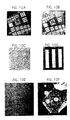
- FIG. 10 shows six examples of numerical reconstruction of digital holograms and is presented here in order to clarify the idea of simultaneous amplitude and quantitative phase contrasts imaging.
- FIGS. 10A and 10B present respectively the amplitude contrast image and the quantitative phase contrast image of an USAF test target.
- the hologram has been recorded in the reflection geometry (the object wave is reflected by the specimen).
- the specimen (USAF test target) is composed of a glass plate on which rectangular reflective elements of several sizes are created by chromium evaporation.
- amplitude contrast FIG. 10A
- the obtained image reveals changes of the reflectance of the specimen
- quantitative phase contrast FIG. 10B
- Both amplitude and quantitative phase contrast images reveal the same pattern because the highest parts of the specimen are also the most reflective.
- FIGS. 10C and 10D present respectively the amplitude contrast image and the quantitative phase contrast image of a pure phase object.
- the hologram has been recorded in the reflection geometry.
- the specimen has been fabricated by evaporating a thin layer of aluminium (70 nm) over the surface of a USAF test target.
- amplitude FIG. 10C
- quantitative phase contrast FIG. 10D
- the obtained image reveals exclusively the topography of the specimen.
- FIGS. 10E and 10F present respectively the amplitude contrast image and the quantitative phase contrast image of a biological cell.
- the hologram has been recorded in the transmission geometry (the object wave is created by the light that is transmitted by the specimen).
- the reconstructed image in amplitude contrast (FIG. 10E) reveals less details than the quantitative phase contrast image (FIG. 10F), the contrast of which is due to differences in the refractive index and/or in the thickness of the specimen.
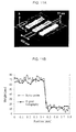
- FIG. 11 is presented here in order to clarify the idea of quantitative phase contrast and shows an example of quantitative measurement performed with the present invention.
- FIG. 11A shows a view in a three-dimensional perspective of the phase contrast image presented in FIG. 10D.
- FIG. 11B is a graph to show an example of quantitative surface profilometry.
- a phase profile has been extracted from the data corresponding to the image presented in FIG. 11A.
- the measured phase values have been converted to height measurements using Eq. (1.22) and reported on the graph of FIG. 11B, the corresponding profile is referred as "Digital holography" and gives a measurement of about 55 nanometers (nm) for the step height.
- the same step height has been measured by scanning a standard contact stylus probe profilometer (Alpha-step 500) over the corresponding area of the sample. As shown in FIG. 11B, both techniques are in excellent agreement.
- a set of holograms (at least two) of the same specimen or of several different specimens can be recorded, acquired, digitized and numerically reconstructed using the various above described methods. It is also clear that each individual hologram can be the hologram of many specimens at the same time or in other words that the specimen can be composed of several specimens.
- this set of holograms can be a time sequence of holograms which have been created, with the same or with an other specimen, at different instants.
- the corresponding numerically reconstructed amplitude and/or quantitative phase contrast set of images represent then the specimen (or the different specimens) at these different instants and this set of reconstructed images can be used in order to build a computed video animation and/or in order to monitor a deformation of the specimen and/or a movement of the specimen and/or a modification of the optical properties of the specimen.
- this set of holograms can contains holograms of the same specimen which have been recorded at the same instant using several image acquisition systems and an appropriate set-up.
- the corresponding reconstructed images represent the specimen with different direction of observations.
- this set of holograms can contain holograms which have been created in the transmission geometry, for different orientations of a semi-transparent or transparent specimen.
- the specimen can be rotated between each hologram acquisition.
- the well-known Fourier slice theorem can be applied to the set of corresponding numerically reconstructed amplitude and/or quantitative phase contrast set of images which are considered as the projections of the specimen along the optical path way.
- Backprojections techniques are also appropriate for the reconstruction.
- diffraction tomography is a known approach which can be applied to the treatment of the set of reconstructed images in order to build a computed three-dimensional tomography of the specimen.
- An other method resulting from the present invention is based on the treatment of a set of holograms obtained after successive modifications of the irradiation wavelength ⁇ . If the holograms are recorded in the transmission geometry with a semi transparent specimen, and provided that the dispersion law of the refractive index is known, the exact thickness of the specimen can be derived.
- An other method resulting from the present invention is based on the treatment of a set of holograms obtained after successive modifications of the irradiation wavelength ⁇ .
- a computed three dimensional description of the specimen can be obtained from the Fourier transform of the set of corresponding reconstructed amplitude and quantitative phase contrast images regularly sampled at wavevectors k z obtained by changing the wavelength. If the set of holograms is recorded in the Fourier configuration, the three-dimensional reconstruction of the specimen can be performed using a three dimensional Fourier transform. If the set of holograms contains Fresnel holograms, the three-dimensional reconstruction of the specimen can be performed using Fourier transform along the direction of the optical axis and a Fresnel transform in the transverse planes.
- the present invention can also be used to reconstruct a hologram which results from the interference between an object wave and more than one reference waves.
- the different reference waves can correspond to different off-axis configurations and the corresponding reconstructed images will appear at different locations of the observation plane.
- the hologram can be created using two reference waves with crossed polarizations and with different directions of propagation.
- a Wollaston prism can be used to perform this separation in direction and polarization.
- two reconstructed images corresponding to the crossed polarization can be observed separately and used to measure the birefringence and the dichroism of the specimen.
- the present invention can also be used to reconstruct a hologram which results from the interference between one reference wave and more than one object waves.
- the present invention can also be used to reconstruct a hologram which results from the interference between more than one reference wave and more than one object waves.
- the present invention can be applied to reconstruct a hologram which can be expressed as follow: where i and j are integers (i, j ⁇ 1).
- the reconstruction of such holograms produces several images which can be reconstructed separately with different values of the reconstruction parameters.
- the reconstruction method do not require a calculation of scalar diffraction.
- a commonly used method consists in analysing the interferogram using a Fourier method.
- the hologram is digitally Fourier transformed and the obtained two dimensional spectrum is spatially filtered in order to eliminate all spatial frequencies except those of one of the interference term R*O or RO*.
- phase unwrapping methods (which are often time consuming) are applied to eliminate the contribution of the reference wave in order to obtain the phase distribution of the object wave.
- phase unwrapping method using a computed digital reference wave and a computed phase mask which multiply the complex field obtained after calculation of the inverse Fourier transform.
- the digital phase mask and the digital reference wave can also be adjusted using the methods described above.
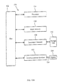
- Figure 12 a illustrate an exemplary portion of a generalized computer system 500 upon which portions of the invention may be implemented.
- the configurations illustrated in Figures 1-3 and 5-6 may each be implemented in a plurality of computers having a generalized configuration as exemplified by Figure 12a or by a plurality of computers having the configurations similar to those of Figures 12a and 12b described below.
- An input 502 of Figure 12a communicates with a memory 504 and a central processing unit 508.
- the central processing unit 508 communicates with the memory 504.
- the central processing unit 508 may include an arithmetic/logic unit and a control unit in the form of hardware and/or software (not shown).
- One or more inputs 502 may each be in communication with one or more memories 504 and /or central processing unit 508.
- One or more central processing unit 508 may be in communication with one or more outputs 506 and/or memories 504 and /or inputs 502.
- One or more memories 504 may be in communication with one or more inputs 502 and /or central processing unit 508 and /or outputs 506.
- a plurality of variations of computer hardware configurations may be realized in a network of computers systems upon which portions of the invention may be implemented.
- Figure 12b illustrates an exemplary hardware configuration of a generalized computer system 520 upon which portions of the invention may be implemented.
- One or more processors 524 are connected to a communication bus 522.
- the communication bus 522 also communicates with a main memory 526, preferably a random access memory ("RAM").
- a secondary memory 528 communicating with the communication bus 522 may also be included in the computer system 520.
- the secondary memory 528 may include, for example, a hard disk drive, a removable storage drive such as a floppy disk drive, a magnetic tape drive, an optical disk drive, a program cartridge and cartridge interface, a removable memory chip (e.g. EPROM, PROM, ROM), or any other similar storage medium.
- the secondary memory 528 may be in communication with a storage unit 530 such as a floppy disk, magnetic tape, optical disk, or others storage medium read by and written by a secondary memory device.
- the storage unit 530 includes a computer usable storage medium for storing computer software and date.
- the computer system 520 may also include a communication interface 532 in communication with the communication bus 522 for transferring software and data between the computer system 520 and external devices.
- Examples of communication interfaces 532 include a modem, a network interface(e.g. a network card), a communication port, a PCMCIA slot and card, and other similar interfaces.
- Software and data transferred via the communication interface 532 are in the form of signals 536 which are provided to the communication interface 532 via a channel 534.
- the signals 536 may be electronic, electromagnetic, optical, or other signals capable of being received by the communication interface 532.
- the channel 534 may be implemented using wire, cable, fiber optics, a phone line, a cellular phone link, a RF link, an IR link, or other communication channels.
- Computer programs are stored in main memory 526 and /or secondary memory 528. Computer programs may be received via the communication interface 532. Computer programs, when executed by the processor 524, enable the computer system 520 to perform the features of the present invention.
- the invention can be conveniently implemented using a network of conventional computer and/or microprocessors programmed according to the teachings of the present specification, as will be apparent to those skilled in the computer art from reading above descriptions regarding figures 1-12b.
- Appropriate software coding can be readily be prepared by skilled programmers based on the teachings of the present disclosure, as will be apparent to those skilled in the software art.
- the invention may also be implemented by the preparation of application specific integrated circuits or by interconnecting an appropriated network of conventional components circuits, as will be readily apparent to those skilled in the art.
- the present invention includes a computer program product which is a storage medium including the instructions which can be used to program a computer or a plurality of networked computers to perform a process of the invention.
- the storage medium can include but it is not limited to, any type of disks including floppy disks, optical disks, CD ROMs, and magneto-optical disks, ROMs, RAMs, EPROMs, EEPROMs, magnetic or optical cards of any type of media suitable for storing electronic instructions.
Landscapes
- Physics & Mathematics (AREA)
- General Physics & Mathematics (AREA)
- Engineering & Computer Science (AREA)
- Computing Systems (AREA)
- Theoretical Computer Science (AREA)
- Holo Graphy (AREA)
Abstract
Description
- The present invention relates to a method for simultaneous amplitude and quantitative phase contrast imaging by numerical reconstruction of digitally encoded holograms.
- The basic idea with the present invention is to record a hologram of the specimen and to reconstruct this hologram with a numerical method. This idea has been reported for the first time in 1967 by J.W. Goodman and R. W. Laurence , "Digital image formation from electronically detected holograms," Appl. Phys. Lett. 11, 77-79 (1967), who used a vidicon detector for the hologram recording, and in 1971 by M.A. Kronrod et al. "Reconstruction of a hologram with a computer," Soviet Phys.-Technical Phys. 17, 333-334 (1972), who used a digitized image of a hologram recorded on a photographic plate. In these two references, the holograms were recorded in the holographic Fourier configuration for which amplitude contrast images of the specimen can be numerically reconstructed by simply calculating the modulus of the two-dimensional Fourier transform of the hologram. A recent development using a Charged Coupled Device (CCD) camera as recording device, also in the Fourier configuration, has been patented (U.S. Pat. 4,955,974 and U.S. Pat. 5,214,581) and reported by W.S. Haddad et al. "Fourier-transform holographic microscope," Applied Optics 31, 4973-4978 (1992), and by K. Boyer et al. "Biomedical three-dimensional holographic microimaging at visible, ultraviolet and X-ray wavelength," Nature Medicine 2, 939-941 (1996), for X-ray amplitude contrast imaging of biological specimens.
- In 1994, on the basis of precedent works about digital holography (L.P. Yaroslavskii and N.S. Merzlyakov, "Methods of Digital Holography'', Consultants Bureau, New York, 1980), Schnars et al. "Direct recording of holograms by a CCD target and numerical reconstruction,'' Applied Optics 33, 179-181 (1994), have reported the first numerically reconstructed amplitude contrast image from an off-axis hologram recorded in the Fresnel holographic configuration with a CCD camera. With the same reconstruction algorithm but with a low-coherence light source, E. Cuche et al. "Optical Tomography at the Microscopic scale by means of a Numerical Low Coherence Holographic Technique," Proceedings SPIE on Optical and Imaging techniques for Bioimaging, Vienna, Vol. 2927, 61-66 (1996), have reported an application of numerical holography for tomographic imaging. An application in micro-endoscopy, using also a Fresnel calculation for the hologram reconstruction, has been reported by O. Coquoz et al. ''Performances of endoscopic holography with a multicore optical fiber," Applied Optics 34, 7186-7193 (1995).
- All the above mentioned works concern amplitude contrast imaging for which only the modulus of the numerically reconstructed optical field is considered. As shown here, when the argument is calculated, phase contrast imaging is possible. The first use of a numerically reconstructed phase distribution, from a Fresnel hologram, has been reported by Schnars et al. "Direct phase determination in hologram interferometry with use of digitally recorded holograms," J.Opt.Soc.Am.A 11, 2011-2015 (1994), for an application in holographic interferometry. As presented in this reference Applicant's comments: Only the dot symbol should de deleted, the used reconstruction algorithm is the same as for amplitude contrast imaging and do not really allows phase contrast imaging, because, in this case, the reconstructed optical field is the product of the object wave by the complex conjugate of the reference wave (or the product of the complex conjugate of the object wave by the reference wave). However, this reconstruction algorithm can be used in holographic interferometry, because the subtraction between two reconstructed phase distributions obtained with the same reference wave provides an image which represents only the phase difference between the deformed and undeformed states of the object.
- The first example of a numerically reconstructed phase contrast image has been reported in 1997 by E. Cuche et al. "Tomographie optique par une technique d'holographie numérique en faible coherence," J. Opt. 28, 260-264 (1997), who have used a modified reconstruction algorithm including a multiplication of the digital hologram by a digital replica of the reference wave (digital reference wave). In this reference, the phase contrast image has been obtained with a plane wave as reference and in direct observation, meaning that no magnification or demagnification optics is introduced along the optical path of the object wave.
- In comparison with existing methods for phase contrast microscopy, such as the Zemicke or the Nomarski methods, the present invention provides a straightforward link between phase contrast imaging and optical metrology.
- "Quantitative phase contrast" means that the phase contrast image is free of artifacts or aberrations and can be directly used for quantitative measurements of optical properties (e.g. refractive index) or structural informations (e.g. topography, thickness). More precisely, "quantitative phase contrast'' means here that the value of each pixel of the phase contrast image is equal, modulo 2π, to the value of the phase of the object wave at the corresponding area of specimen.
- "Simultaneous amplitude and quantitative phase contrast" means that two images of the specimen can be reconstructed from the same hologram. One of these images with an amplitude contrast and the other one with a quantitative phase contrast. These images can be analyzed separately or compared the one with the other. Their information content (or the information content of several pairs of images reconstructed for different orientations of the specimen) can be associated in order to build a computed three-dimensional description of the specimen, for example a three-dimensional tomography of semi-transparent specimens. Spectroscopic measurements are also possible with the present invention by recording two or more holograms of the same specimen at different wavelengths. Such multi-wavelength procedure can also be useful for the precise determination of objects dimensions or refractive index in metrology.
- In comparison with standard interference microscopy techniques which also provides simultaneously amplitude and quantitative phase contrasts, the advantage of our invention is that the recording of only one hologram is necessary while the recording of four or more interferograms is required with interference microscopy. Moreover, no displacement or moving of optical elements is needed with the present invention. As a consequence, the acquisition time is reduced providing a lower sensitivity to thermal and mechanical drifts. Robustness is a great assess of the present invention.
- An other important advantage of the present invention in comparison with interference microscopy is that the phase aberrations are corrected digitally. Indeed, a microscope objective which is introduced in an interferometer produces a curvature of the wavefronts which affects the phase of the object wave. Therefore, for phase contrast imaging with the present invention or more generally in any interferometric system, this phase aberration function must be corrected. In interference microscopy, this problem is solved experimentally by inserting the same microscope objective in the reference arm, at equal distance from the exit of the interferometer. This arrangement called Linnick interferometer requires that if any change has to be made in the object arm, then the same change must be precisely reproduced in the reference arm in such a way that the interference occurs between similarly deformed wavefronts. As a consequence the experimental configuration requires a very high degree of precision. An other possibility (Mirrau interferometry) consists in magnifying the interference pattern. However, it is difficult to achieve high resolution imaging with this technique because a miniaturized interferometer must be inserted between the sample and the microscope objective. Here we propose a purely digital method which allows us to perform the correction by multiplying the reconstructed wavefront with the computed complex conjugate of the phase aberration function.
- Depending on the configuration used for the recording of the hologram, the physical interpretation of amplitude and quantitative phase contrasts vary. If the hologram is recorded with the wave that is reflected by the specimen (reflection geometry), the amplitude contrast depends on variations of the reflectance at the specimen surface and the phase contrast depends on the topography of the specimen and/or on changes of the phase shift at the reflection. If the hologram is recorded with the wave that is transmitted by a transparent or semi-transparent specimen (transmission geometry), the amplitude contrast is related to changes in absorption and the phase contrast depends on variations of the thickness and/or of the refractive index (or more generally on variations of the optical path).
- In most cases, quantitative measurements of optical properties or structural informations, on the basis of phase measurements is ambiguous because phase contrast generally has more than one origin. For example, the measurement of the refractive index of a transparent specimen requires the knowledge of the thickness and inversely the measurement of the thickness requires the knowledge of the refractive index. For topographic measurements with specimens composed of different materials, the analysis of the results must take into account the variation of the phase change on the reflection interface, if the complex index of refraction of the different materials is not the same. If a pure topographic or a pure refractive index or a pure thickness measurement is desired, known methods such as ellipsometry or multi-wavelength measurements could be used in combination with the present invention. In particular, refractive index measurement on a transparent specimen of unknown thickness can be performed by recording two or more holograms at different wavelengths. Assuming that the thickness of the specimen is constant for each hologram, variations of the reconstructed phase distributions are due to variations of the refractive index as a function of the wavelength. Using a model describing the variation of the refractive index as a function of the wavelength, the refractive index of the specimen or its thickness can be deduced from the quantitative phase contrast images. With a semi-transparent specimen (e.g. biological cells or tissues) or more generally with a 3D scene composed of several reflective elements located at different depth, if a gating technique is used, such as time or coherent gating, the hologram can be recorded, in the reflection geometry, with the light that is reflected by a selected slice inside the specimen. In this case, both contrasts (amplitude and phase) depend on the optical properties of the selected slice and on the optical properties of other volumes inside the specimen where the light has traveled before and after the reflection.
- The present invention provides a more general method for the numerical reconstruction of both amplitude and quantitative phase contrast images from a digital hologram. The numerical method for the hologram reconstruction comprises the calculation of a digital replica of the reference wave called digital reference wave. An array of complex numbers called digital phase mask is also calculated in order to correct the phase aberrations of the imaging system.
- The present invention provides unique results. The technique provides a quantitative phase contrast meaning that the reconstructed phase distribution can be directly used for applications in metrology, in particular for surface profilometry, refractive index measurements or more generally for quantitative material testing (shape and position measurements, surface roughness measurement, optical properties measurement). Moreover, an amplitude contrast image of the specimen can be reconstructed from the same hologram. It is an important feature of the present invention that a three dimensional description of the specimen can be obtained digitally with only one image acquisition.
- The possibility of instantaneous acquisition of the amplitude and of the quantitative phase with a pulsed source or a time gated camera is a great advantage of the present invention.
- Basically, the numerical reconstruction method performs a calculation which describes the propagation of the wavefront that would be diffracted by the hologram during a standard holographic reconstruction. The calculation consists in a numerical evaluation of the diffraction pattern which is produced in an observation plane when the hologram is illuminated by a replica of the reference wave. The scalar description of the diffraction is considered here and the reconstruction method consists in the numerical calculation of the Fresnel-Kirchhoff integral or of the Rayleigh-Sommerfeld integral. Depending on the configuration used for the hologram creation, the diffraction calculation can be performed using an approximation of these integrals such as the Fraunhofer or the Fresnel integrals. In some cases such as Fourier holography, a simple Fourier transform calculation can be used.
- In a preferred manner, the configuration used for the hologram creation, in particular the distance between the hologram and the specimen, will be adjusted in such a way to produce a Fresnel hologram for which the diffraction calculation can be performed in the Fresnel approximation. The advantage of the Fresnel approximation is that the computations are simple and can be performed very fast using a discrete formulation of the Fresnel integral expressed in terms of a Fourier transform. In addition, a wide range of experimental configurations are covered by the Fresnel approximation.
- An important feature of the present invention is that image reconstruction, in both amplitude and phase contrast requires the adjustment of several constants which are involved by the numerical reconstruction method. These constants are called reconstruction parameters and their values are defined by the experimental configuration. The reconstruction parameters can be divided into three categories: the reconstruction distance which is related to image focusing; the reference wave parameters which are related to the definition of the digital reference wave; and the phase aberration function correction parameters which are related to the definition of the digital phase mask. It is an object of the present invention to describe how these reconstruction parameters are defined and how their values must be adjusted. It is clear that the values of the reconstruction parameters are fixed for a given experimental configuration and that the same values of the reconstruction parameters can be used to reconstruct several holograms without new adjustment procedures if the experimental configuration is the same for these holograms.
- Other parameters such as the wavelength, the detector size and the number of pixels are requested by the numerical reconstruction method but these parameters have, in general, constant values and do not require a special adjustment.
- An apparatus is disclosed, which make use of the different aspects of the method for simultaneous amplitude and quantitative phase contrast imaging by numerical reconstruction of digital holograms. Depending on the size and accessibility of the object, three different implementations of the apparatus are disclosed : Numerical Holographic Telescope (NHT) Numerical Holographic Microscope (NHM) and finally Numerical Holographic Endoscope (NHE).
- Other objects and features of the present invention will become apparent from the following detailed description considered in conjunction with the accompanying drawings. It is to be understood, however, that the drawings are designed solely for purposes of illustration and not as a definition of the limits of the invention, for which reference should be made to the appended claims.
-
- FIG.1 is a view showing diagrammatically the different steps of the imaging procedure.
- FIG.2A is a view showing diagrammatically one of the possible configuration for the recording of an off-axis hologram. FIG. 2B, 2C and 2D are views showing diagrammatically two of the possible realization of the set-up. FIG. 2B in a Michelson configuration or more generally Twyman-Green interferometers can be considered. FIG. 2C in a Mach-Zender configuration for transmission imaging. FIG. 2D in a Mach-Zender configuration for reflection imaging.
- FIG.3 is a view showing diagrammatically the standard optical reconstruction of an off-axis hologram which has been recorded as presented in FIG. 2A.
- FIG.4 is a view showing diagrammatically the different steps of computations of the numerical method for the reconstruction of a digital hologram.
- FIG.5 is a view showing diagrammatically an other possibility for the computation of the numerical method for the reconstruction of a digital hologram.
- FIGS.6A to 6C are a views showing diagrammatically three of the possible configurations when a magnification optics is introduced along the optical path of the object wave, for the creation of a hologram of a magnified image of the specimen.
- FIGS.7A to 7C show three examples of numerically reconstructed amplitude contrast images of a USAF test target obtained with different reconstruction distances.
- FIGS.8A to 8C show examples of numerically reconstructed phase contrast images of a biological cell. For theses images, a plane wave has been used as reference for the hologram creation and a microscope objective has been used as magnification optics. FIG. 8A shows the phase contrast image obtained when all the reconstruction parameters are adequately adjusted, FIG. 8B shows the result obtained with an inadequate adjustment of the phase aberration function correction parameters. FIG. 8C shows the result obtained with an inadequate adjustment of the reference wave parameters.
- FIG.9 is a view showing diagrammatically the different possibilities for the adjustment of the values of the reconstruction parameters.
- FIGS. 10A to 10F show examples of simultaneously reconstructed amplitude and quantitative phase contrast images. FIGS. 10A and 10B show respectively the amplitude contrast image and the quantitative phase contrast image of a USAF test target. FIGS. 10C and 10D show respectively the amplitude contrast image and the quantitative phase contrast image of a pure phase object. FIGS. 10E and 10F show respectively the amplitude contrast image and the quantitative phase contrast image of a biological cell.
- FIG. 11A is a three-dimensional perspective of a numerically reconstructed phase distribution to show the topography of a pure phase object.
- FIG. 11B is a graph to show an example of quantitative measurement (profilometry) with quantitative phase contrast imaging.
- FIG. 12A illustrates an exemplary portion of a generalized computer system upon which portions of the invention may be implemented and
- FIG: 12B illustrates an exemplary portion of a generalized hardware configuration, in the format of a workstation, upon which portions of the invention may be implemented.
-
- The embodiments of the present invention will be described in more details with reference to the drawings.
- FIG. 1 shows diagrammatically the different steps of the entire imaging procedure. The beam emitted by an illumination source 1 illuminates a set-up 2 which creates a hologram 4 of the specimen 3. The set-up 2 collects the light from the illumination source 1 and provides illumination 1 of the specimen 3 . It includes also a device for creating a reference wave R and a device for creating an object wave O from the light that is transmitted or reflected or scattered by the specimen 3. The object wave O and the reference wave R are combined in such a way that they interfere in a plane.
- In the following, the object wave will be understood as the part of the illumination wave which has been transmitted, reflected or more generally scattered by the object and captured by the optical system.
- The interference between the reference wave R and the object wave O creates the hologram 4 which can be described as a two-dimensional distribution of intensity:
- The present invention is not restricted to the optical domain and can be applied for the numerical reconstruction of holograms recorded with any kind of electromagnetic (e.g. X-ray) or non-electromagnetic (e.g. acoustics or heat) waves. Photon density waves can also be used. For this reason, the nature, the wavelength and the coherence of the illumination source 1 are not specified here. Gas lasers, semiconductor lasers, solid state lasers, laser diodes, superluminescent diodes, narrow and broadband sources, white light sources, X-ray sources, and electron beam are examples of means which can be used as illumination source.
- A combination of two or more illumination sources can also be used. For example, two illumination sources of different wavelengths can be combined in order to create an illumination source with a so called synthetic wavelength.
- In a preferred manner, the set-up 2 is designed in such a way that the polarization of the reference wave R matches (as close as possible) the polarization of the object wave O. This closeness of the polarization of the object to that of the reference waves is important to optimise the interference between these two waves. If the object wave contains different kind of photons with different polarization states, as it happens for example when scattering events occur inside the specimen or when the birefringence of the specimen is not uniform, working with a fixed polarization of the reference wave allows one to select the photons of the object wave, the polarization of which is close to the polarization of the reference wave.
- The device which creates the object wave O includes magnifications optics or demagnification optics.
- The term "magnification optics" is to be understood as being a single lens or an assembly of lenses and/or optical fibers which produces a magnified image of the specimen with a better resolution than direct imaging. The case of a magnification optics producing an image of the specimen, the size of which is the same as the size of the specimen (magnification equal to unity), is also included here.
- The term ''demagnification optics" is to be understood as being a single lens or an assembly of lenses and optical fibers which produces a smaller image of the specimen in order to allow imaging of larger specimens than direct imaging.
- In a preferred manner, the set-up 2 will be designed in order to produce an off-axis hologram. The term "off-axis hologram" is to be understood as meaning that the directions of propagation of the reference wave R and of the object wave O are not parallel, at their incidence on the plane where the hologram is created. The off-axis geometry advantageously permits to separate the zero order of diffraction, the real image and the twin image during the reconstruction. Several configurations can be used for the creation of an off-axis hologram. FIG. 2A presents one of the possible configurations with an angle between the directions of the object wave and of the reference wave at their incidence on the hologram plane.
- Depending on the resolution of the media used for hologram recording, the off-axis geometry may be restricted to small angles in order to avoid that the spatial frequency of the created interferogram exceeds the resolution power of recording media. In other word, the angle between the reference wave and the object wave, at their incidence on the plane where the hologram is created, must not exceed a certain value for which the interference fringes of the hologram are not resolved by the image acquisition system. The off-axis geometry may even be considered at the limit of very small angles, but in this case, the zero order of diffraction may cover parts or integrality of the twin image or of the real image. In this case, additional methods can be used in order to suppress the zero order of diffraction. For example, a method proposed by T.M. Kreis and W.P.O. Jüptner , ''Suppression of the dc term in digital holography,'' Opt. Eng. 36, 2357-2360 (1997), can be applied before the numerical reconstruction. However, this method, which consists in subtracting the mean intensity from the digital hologram permits only the elimination of the so-called dc term of the zero order of diffraction from the reconstructed images. In other words, if a reference wave of constant amplitude (for example a plane wave) is used for the hologram creation, the method proposed by.M. Kreis and W.P.O. Jüptner can be described as being a method which produces a hologram of the following form:
- As a consequence, the object component of the zero order of diffraction (| O |2), which is in general not constant in the hologram plane, is not suppressed by this method.
- We propose here a method for the complete elimination of the zero-order of diffraction. In principle, this method can also be applied when the amplitude of the reference wave is not constant. In a general way, this method can be described as being a method which produces a hologram which contain only the interfering terms of the hologram:
- Such a result can be obtained by subtracting a locally evaluated value of the zero order of diffraction (| R |2 +| O |2) from the digital hologram. For example, the digital hologram can be divided in small elements called submatrix of constant (or non-constant) sizes, and the method proposed by T.M. Kreis and W.P.O. Jüptner can be applied to each of these submatrix. The size and the number of the submatrix must be chosen in such a way to restore, with enough precision, the variations of the zero order of diffraction in the hologram plane. However the size of a submatrix must not be smaller than a minimum size for which a submatrix contains only one constructive and one destructive interference.
- Another aspect of the present invention is based on the application of a band-pass filter to the Fourier transform of the digital hologram, and which also allows for the complete elimination of the zero-order of diffraction This method is based on the fact that, in off-axis holography, the spatial frequencies corresponding the interfering terms ( R*O and RO*) are higher than the spatial frequencies which correspond to the zero order of diffraction (| R |2 +| O |2). As a consequence, we propose to apply, optionally, before the numerical reconstruction of the digital hologram, a digital image processing method which comprises the steps of:
- computing the two dimensional (2D) discrete Fourier transform of the digital hologram;
- locating, in the Fourier transform of the digital hologram, the spatial frequencies which correspond to the interfering terms R*O and RO*.
- computing the multiplication of the Fourier transform of the hologram by a 2D function which eliminates or attenuates the spatial frequencies which do not correspond to the interfering terms. This operation removes (or attenuates) the spatial frequencies which correspond to the zero order of diffraction and can also remove other parasitic spatial frequencies;
- computation of the discrete inverse Fourier transform.
- At this step, as a consequence of the suppression of the low spatial frequencies of the hologram, a filtered digital hologram with a constant zero order is obtained. The value of the zero order is equal to the mean intensity calculated for the entire hologram area. Therefore, the zero order can be completely suppressed by subtracting the mean intensity to the intensity of each pixel of the filtered digital hologram.
- With reference to FIG.1, the application of the above mentioned Fourier filtering image processing is one of the possible digital image processing which can be optionally applied before and/or after the numerical reconstruction of the hologram. At this step, several digital image processing treatments can be applied in order to improve the signal to noise ratio or in order to enhance the fringes visibility of the digital hologram 7. For example brightness and contrast adjustment, offset subtraction, modification of the distribution of grey levels, thresholding, application of phase unwrapping methods to the quantitative phase contrast image, application of histogram equalization, application of two-dimensional high-pass spatial frequency filters or low-pass spatial frequency filters, application of one or several two-dimensional band-pass spatial frequency filters, application of statistical operations on a set of several images, application of image processing treatment in order to suppress the zero order of diffraction and/or the twin image and/or the real image. It is also possible to increase or to decrease the number of pixels of the digital hologram. The digital hologram can also be multiplied by a two-dimensional function (for example a Hanning or a Hamming or a Gaussian window) in order to perform data windowing.
- This feature of a possible digital image processing treatment of the hologram is one of the advantage of the present invention in comparison with standard holographic methods which use, for example, photographic plates as recording media and which do not allow for such a straightforward processing of the hologram, before its reconstruction.
- A particularly interesting digital treatment consists in multiplying the hologram by a two dimensional real function which modifies the transmission (or the amplitude transmittance) of the hologram aperture in order to perform an apodization of this aperture. Aperture apodization is a well known technique in optics and is used to reduce diffraction effects (fluctuation of the diffracted field in amplitude and phase) arising when a beam of coherent light is truncated by an aperture. An apodized aperture is characterized by an amplitude transmittance (transmission) which does not change abruptly from zero to unity at the edge of the aperture, but in a smooth and continuous manner. Several kind of continuous functions can be used to define the transition of the transmission (from zero to unity) at the edge of the aperture: Gaussian, Super Gaussian, trigonometric or a combination of functions. A transmission function defined iteratively during an optimisation process can also be used. In a preferred manner, the transmission function of the apodized aperture is defined in such a way that a large region in the center of the aperture remains transparent.
- Assuming that with off-axis holography the zero order of diffraction corresponds to low spatial frequencies, its suppression can also be performed experimentally by spatially filtering the hologram 4 before acquisition of the image. This operation can be performed using a non linear optical element and a so-called 4-f system composed of two lenses of focal length f with a high-pass mask located in the Fourier plane of the first lens. With reference to FIG. 2B, such a 4-f system can be considered as being an example of said optional optical elements which can be inserted between the beam splitter and the image acquisition.
- The extreme case of in-line or Gabor holograms can also be considered with the present invention. In this case, the present invention can be used in combination with other methods (image processing methods or experimental procedures) for the elimination of the zero order of diffraction and/or for the elimination of the twin or real image. For example, a method which is similar to interference microscopy has been proposed by I. Yamaguchi and T. Zhang "Phase-shifting digital holography", Opt. Lett. 22, 1268-1270 (1997). This method requires the recording of four interferograms taken with phase shifts (of 90°) of the reference wave and allows the suppression of both the zero order of diffraction and the twin image. In this case, or more generally when a procedure is used to shift or to modulate the phase of the reference wave and/or the phase of the object wave, the object wave can be measured in amplitude and phase in the hologram plane. The present invention can then be used in order to recover the amplitude and the phase at the surface of the specimen. Piezo actuated mirrors, acousto-optics or electro-optics or photo-elastic modulators are example of optional optical elements which can be used to modulate or to shift the phase of the reference wave and/or of the object wave.
- The different methods reported in the present invention mostly refer to the use of homodyne detection: it is assumed that the frequency or wavelength of the reference wave is the same as the frequency or wavelength of the illumination wave, giving steady holograms which are acquired and digitized according to the described invention. Nevertheless the present invention also apply to optical systems wherein heterodyne detection may be used.
- For a heterodyne detection, said means which creates the reference wave R can comprise a device which modifies the wavelength of the reference wave with respect to the wavelength of the object wave. A similar device can also be inserted in said means which creates an object wave O. Acousto optic modulators, electro-optic modulators, photo-elastic modulators, piezo-electric driven mirrors are example of means which can be used to modulate the wavelength of the reference wave and/or of the object wave. These means are example of optional optical components featured in FIGS 2B, 2C, 2D. Physically distinct sources can also be used for the illumination and for the creation of the reference.
- In a preferred manner, the set-up 2 will be designed in order to produce a Fresnel hologram. The term "Fresnel hologram'' is to be understood as meaning that the hologram reconstruction can be performed by a calculation of scalar diffraction in the Fresnel approximation. The numerical calculation of the discrete Fresnel integral will be explained in details further. The advantage of the Fresnel approximation is that the computations are simple and can be performed very fast. In addition, a wide range of experimental configurations are covered by the Fresnel approximation.
- If the set-up 2 used for the hologram creation do not satisfy the conditions of the Fresnel approximation, other approximations or exact evaluation of the Fresnel-Kirchoff or Rayleigh-Sommerfeld integrals can be used as models for the diffraction calculation.
- A simple Fourier transform calculation or a diffraction calculation in the Fraunhofer approximation can also be used.
- If a low-coherence illumination source is used, the set-up 2 will also comprise means which allow for the adjustment of the length of the path of the reference wave R . These means may be different or confounded with the means to form the reference wave: prisms, parallel plate, mirrors, gratings, optionally mounted on mechanical actuators of any kind: mechanical, magnetic actuator and piezo-electric translators. It may include also optional optical elements like optical modulators: piezoelectric modulator, acousto-optical modulators, elasto-optical modulators and phase modulators: electro-optical modulators, liquid crystals modulators. Such a device is an example of optical components featured in FIGS 2B, 2C, 2D.
- FIG. 2B, FIG. 2C and FIG. 2D present three possible realizations of the set-up 2. As shown in FIG. 2B, the set-up consists basically of a Michelson interferometer, or more generally a Twyman-Green interferometer, designed for imaging in the reflection geometry. The beam emitted by the illumination source is expanded in diameter and the interferometer comprises a microscope objective in the object arm and a mirror in the reference arm which reflects a plane wave as reference R . If the mirror is tilted. with two degrees of freedom, off-axis holograms can be recorded. As shown in FIG. 2C, the set-up consists basically of a Mach-Zender interferometer designed for imaging in the transmission geometry. The interferometer comprises two beam expanders in each arm of the interferometer. A configuration with only one beam expander located just after the illumination source can also be used. The beam expanders can include a pinhole for spatial filtering. In the object arm, a microscope objective collects the light that is transmitted by the specimen. In the reference arm, a mirror which can be tilted reflects a plane wave as reference R. As shown in FIG. 2D, the set-up consists basically of a Mach-Zender interferometer designed for reflection imaging. In the set-up of FIG. 2D, a lens with a long focal length is inserted between the beam expander and the microscope objective. This lens acts as a condenser and its position is adjusted in order to illuminate the sample through the microscope objective with a collimated beam. This condenser is important for reflection imaging because, as explained later, in holographic microscopy the specimen can be located near the object focal plane of the microscope objective. If necessary, for example if a high intensity is desired for the object illumination, a condenser can also be inserted before the specimen in the transmission geometry presented in FIG. 2C. This condenser is an example of optical components featured in FIG. 2C. These examples of set-up are adequate for the creation of Fresnel off-axis holograms. Additional elements called optional optical elements (see FIGS. 2B, 2C, and 2D) can be introduced in both arms of the interferometer and/or before and/or after the beam splitters located at the entrance and/or at the exit of the interferometers. Neutral density filters, prisms, half-wave plates, quarter-wave plates, polarizing plates, Wollaston prisms, iris diaphragms, lenses, spatial filters, pinholes are examples of optional optical elements. As shown in dotted lines in Fig. 2C, a Wollaston prism, inserted close to the recombination beam splitter, can be used to separate the reference wave onto two components with cross polarization and different directions of propagation (dotted line). Polarizing beam splitters can also be used instead of simple beam splitters.
- The advantage of a configuration based on a standard interferometer configuration is that it allows the recording of off-axis holograms with very small angles between the directions of propagation the object and reference waves. This feature is important when low-resolution media such as CCD camera are used as image acquisition systems. In addition, these configurations based on a standard interferometer geometry are appropriate for the creation of Fresnel holograms of small specimen.
- In the examples of set-up presented in FIGS. 2B, 2C and 2D, or more generally in any kind of set-up, optional optical elements can be inserted along the paths of the reference wave and/or along the path of the object wave. For example, modulators which modify the wavelength and/or the amplitude and/or the frequency and/or the polarization and/or the phase and/or the optical path length of the waves. Polarizers, half and quarter wave plates, Wollaston prisms, neutral density filters, acousto-optic modulators, liquid crystal devices, dielectric media, assembly of prisms and/ or mirrors are example of means which can be used as optional optical elements.
- Many other configurations, can be used for the design of the set-up 2, FIG. 2B, 2C and 2D are just shown here as illustrations of possible examples. Most of the designs of interferometers can be used to form a digital holographic set-up.
- Between the plane where the hologram is created and the plane where an image of the hologram is acquired, an assembly of optics components (for example lenses, Hopkin relay optics and optical fibers) can be introduced. For example, the hologram can be recorded at the distal end of a rigid or flexible endoscope.
- With a magnification optics or a demagnification optics introduced along the path of the object wave, the present invention includes a digital method for the correction of the associated aberrations.
- The term "phase aberration functions" is to be understood as being a deformation of the wavefronts which travel across a magnification or demagnification optics. The correction of the phase aberration functions compensate this wavefronts deformation and allows to recover the phase distribution of the original wavefronts.
- An image acquisition system 5 acquires an image of the hologram 4 (Fig.1). Any kind of existing or further developed image acquisition system or image sensor can be used. Because the numerical reconstruction method is fast, rapid or real-time acquisition systems such as video camera can be used. Charged Coupled Device (CCD) camera, intensified or cooled CCD, progressive scan CCD, line-scan camera, electron bombardment CCD (EB CCD) high resolution camera, integrating CCD, numerical or digital camera, CMOS image sensors, array of photodiodes, array of sensors, array of acoustic sensor, are examples of means which can be used as image acquisition system. Slower image acquisition systems which acquires an image of the hologram by scanning a sensor in a plane with a mechanical device can also be used. An image of the hologram can also be recorded on a photographic plate, on a photopolymer film or using an other photo-chemical process. A photorefractive crystal can also be used as image acquisition system.
- In order to allow the transfer of the image to a computer, an image digitizer 6 performs the digitalization (typically a framegrabber or more generally a device which performs an analog to digital conversion) of the acquired image of the hologram.
- Objects and features of the method for the numerical reconstruction of the digital hologram are described in more details in the following.
- The image resulting from the various means described previously is called a digital hologram 7 and is an array I H(kΔx,lΔ y) of Nx x Ny digitally encoded numbers which results from the two-dimensional spatial sampling of the hologram intensity I H(x,y). This two-dimensional spatial sampling can be performed by the image acquisition system and/or by the image digitizer. In a preferred manner, the image sensor is rectangular and the spatial sampling is regular (with constant sampling intervals). In this case, I H(kΔx,lΔy) can be expressed from I H(x,y) as follows:where δ(x,y) is a two dimensional Dirac delta function, k,l are integers, Lx × Ly is the area of the acquired image of the hologram (the area of the sensitive surface of the image acquisition system), rect(x,y) is a function the value of which is 1 if the point of coordinates (x,y) is inside the acquired part of the hologram and 0 elsewhere. Δx and Δy are the sampling intervals along the 0x and 0y directions respectively. For example, if the image acquisition system or the image digitizer produces a rectangular image which contains Nx lines along the 0x axis and Ny points per lines along the 0y axis, we have:

- An amplitude contrast image 9 and a quantitative phase contrast image 10 of the specimen 3 are numerically reconstructed from the digital hologram 4. The reconstruction method requires the adjustment of several reconstruction parameters 8 which define the geometry used for the hologram creation (specimen location, characteristics of the reference wave and of the magnification optics). The methods used for the numerical reconstruction of the hologram and the procedure for the adjustment of the reconstruction parameters will be explained in details further.
- The term ''reconstruction parameters" 8 is to be understood as being a set of constants which must be supplied to the program which executes the numerical reconstruction of the hologram. These constants can be supplied to the computer which executes the program by a human operator, by an apparatus which communicates with the computer or by an other program running on the same (or on an other) computer.
- In classical holography, the hologram can be recorded on a photographic plate and the hologram reconstruction is performed optically by illuminating the hologram with a replica of the reference wave R as shown in FIG. 3. The transmitted wavefront Ψ(x.y)=R(x,y)IH(x,y) contains four terms:
- The two first terms of Eq. (1.7) correspond to the zero order of diffraction, the third term to the twin image and the fourth term to the real image. As shown in FIG. 3, if the hologram has been recorded in an off-axis geometry, these three terms can be observed separately in the observation plane 0ξη. For an observer located in front of the hologram (behind the illuminated side), the virtual image appears as emitted by a replica of the specimen located at its initial position, while the real image is a converging term which is focused symmetrically with respect to the hologram. The zero order of diffraction corresponds to the part of the light that is not diffracted by the hologram and propagates along the direction of the reference wave. As shown in FIG. 3, the directions of observation of the twin image and of the real image form an angle of respectively + and - with respect to the direction of the reference wave, where is the angle between the directions of propagation of the reference wave R and of the object wave O during the recording of the off-axis hologram as shown in FIG. 2A. If is small or if the hologram is recorded without incidence angle between the object wave and the reference wave (=0), the real image, the twin image and the zero order can be partially or completely superimposed.
- In the following, 0xy designates the coordinates of the hologram plane and 0ξη the coordinates of the observation plane (the plane where the reconstruction of the hologram takes place).
- As a result of the present invention, the numerical method for the hologram reconstruction simulates the standard optical reconstruction of a hologram. As presented in FIG. 3 the optical reconstruction is performed by illuminating the hologram with the reference wave R and the transmitted wavefront (Eq. (1.7)) propagates from the hologram plane 0xy to an observation plane 0ξη where the real image is focused. With the present invention as we reconstruct a digital hologram, a digital transmitted wavefront ΨD(kΔx,lΔy) is computed by multiplication of the digital hologram I H(kΔx,lΔy) by a digitally computed reference wave R D(kΔx, lΔy) called further the digital reference wave. Taking into account the definition of the hologram intensity (Eq. (1.1)), we have, in the hologram plane:where R is reference wave which has been used for the hologram recording called the experimental reference wave and O is the object wave. The calculation of the digital reference wave R D(kΔx,lΔy) requires the adjustment of several reconstruction parameters and will be described in details further.

- This multiplication by a digital reference wave is essential for phase contrast imaging, because as presented in Eq. (1.8), we can see that if R D is equal to the experimental reference wave R , the product R DR* becomes a real data slowly varying in the hologram plane and the phase of the twin image ( O ) is correctly reconstructed. Similarly, if R D is equal to R *, the product R DR becomes a real data slowly varying in the hologram plane and the phase of the real image ( O*) is correctly reconstructed. In other words, the digital reference wave must be a digital replica of the experimental reference wave or a digital replica of its complex conjugate in order to perform phase contrast imaging.
- FIG. 4 presents diagrammatically the steps of computations for the reconstruction of a digital hologram 7. The terms "reference wave parameters" 13, "reconstruction distance" 12 and "phase aberration function correction parameters" 14 are to be understood as being "reconstruction parameters" 8 (see FIG.1) as defined previously in this section. The entire procedure can be divided into seven steps:
- a. Computation of the digital reference wave: The digital reference wave is an array R D(kΔx,lΔy) of complex numbers which is computed on the basis of an analytical expression of the reference wave f(x,y) 15, the expression of which is defined by the geometrical and optical characteristics of the set-up. The analytical expression of the reference wave involves two sets of reference wave parameters {p amp} and {p ph} 13 which must be adjusted for a precise description of the wavefronts of the digital reference wave. f(x,y) is a two-dimensional complex function which is defined in such a way that the digital reference wave reproduces as well as possible the reference wave R which has been used to create the hologram. f(x,y) can be expressed as follows:where Amp(x,y,{pamp }) and ph(x,y,{pph }) are real functions, which define respectively the amplitude and the phase of f(x,y).

- The computation of the digital reference wave is performed by evaluating f(x,y) for discrete values of x and y: R D(kΔx,lΔy)=f(kΔx,lΔy), where k and l are integers (-Nx /2 ≤ k ≤ Nx/2 and -Ny /2 ≤ l ≤ Ny /2) and where Δx and Δy are the sampling intervals in the hologram plane as defined by Eqs. (1.5) and (1.6). If the spatial sampling of the hologram is performed on an irregular and/or non rectangular network, the computation of the digital reference wave must be performed on the same network.
- For example, if a plane wave (or a good approximation of a plane wave) of given wavelength λ is used for the hologram creation, the digital reference wave can be computed using the following expression:where k x, k y and A R are the reference wave parameters. k x and k y are two real numbers which represent the components of the normalized wavevector (direction of propagation of the plane wave) and A R is real number which represents the amplitude of reference wave.

- For example, if a spherical wave (or a good approximation of a spherical wave) of given wavelength λ is used for the hologram creation, the digital reference wave can be computed using the following expression:where (x R, y R, z R) are the coordinates of the point source with respect to the centre of the hologram plane 0xy and A R is the amplitude of spherical wave at the point source.
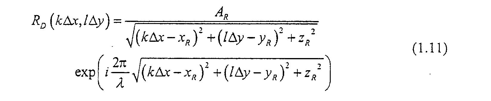
- Paraboloidal waves, Gaussian beams or wavefront representation with Zernike polynomials are other examples of models which can be used for the calculation of the digital reference wave.
- The function which describes the amplitude of f(x,y) (A(x,y)) can also be measured by simply acquiring an image of the reference intensity in absence of interference with the object wave.
- The phase of the digital reference wave can also be measured using an interferometric method with a reference object (a mirror for example or a micro-bead in gold may also be used). The measured phase can be directly used to define the digital reference wave. The interferogram can also be analysed using a fringe analysis method or with a wavefront fitting method. For example the measured wavefront can be fitted with an expansion in Zernike polynomials in order to obtain a measured analytical expression of the reference wave.
- Computation of the multiplication between the digital reference wave and the digital hologram. The result of this multiplication is an array of complex numbers which represents the digital transmitted wavefront in the hologram plane as defined by Eq. (1.8).
- c. Numerical calculation of scalar diffraction: During this step, the propagation of the digital transmitted wavefront, from the hologram plane 0xy to an observation plane 0ξη, is computed by a numerical calculation of scalar diffraction. The distance between the hologram and the observation plane is defined by the reconstruction distance d R 12. Here, it must be specified that the term "observation plane" (coordinates 0ξη) is to be understood as being the plane in which the result of the scalar diffraction calculation is evaluated. In order to obtain well focused reconstructed images, the reconstruction distance d R must be equal to the distance between the specimen and the hologram during the hologram recording. With magnification or demagnification optics, the reconstruction distance must be equal to the distance between the hologram and the magnified (or demagnified) image of the specimen. The calculation of scalar diffraction can be performed by a numerical calculation of the Fresnel-Kirchhoff or Rayleigh-Sommerfeld integrals or by numerical calculation of an approximation of these integrals. In particular, the Fresnel approximation can be used and will be described in details further. The result of this step is called the reconstructed wavefront in the observation plane Ψ(mΔξ,nΔη) 17, where m,n are integers (-N x/2 ≤ m ≤N x/2 and -N y/2 ≤ n ≤ N y/2) and Δξ, Δη are the sampling intervals in the observation plane.
- d. Computation of the phase mask: This step and the next step e. are necessary with the optical set-up used for the hologram creation producing phase aberrations in the observation plane. For example when a magnification optics or a demagnification optics is introduced along the optical path of the object wave. Examples of such a configuration are shown in FIGS. 6A to 6C with a magnification optics (M.O.), of focal length f, which produces a magnified image of the specimen. In FIG. 6A, the image plane 0x 1 yi is located at a distance d i from the plane of the M.O. (0x ϕ y ϕ), the specimen is located in the object plane 0x o y o at a distance d o from the M.O. and the hologram plane 0xy is inserted between the M.O. and the magnified image at a distance d from the image plane. The presented examples of possible arrangements (FIGS 6A to 6C) correspond to standard configurations for holographic microscopy: see: M. Pluta, Holographic Microscopy, in Advances in optical and electron microscopy Vol. 10, (Academic Press, London, 1987). In these cases, the created hologram is not a hologram of the object itself but that of the magnified image. For this reason, the same symbol d designates the specimen-hologram distance in direct imaging (for example as presented in FIG. 2A) and the magnified (or demagnified) image-hologram distance in presence of magnification (or demagnification) optics (for example as presented in FIGS. 6A to 6C). Three possibilities exist for the location of the hologram plane 0xy with respect to the location of the magnified (or demagnified) image of the specimen. In FIG. 6A, the hologram is created (by interference with the reference wave R ) between the M.O. and the magnified image. In FIG. 6B, the hologram is created behind the magnified image. It is also possible to create a hologram of a virtual (magnified as in FIG. 6C or demagnified) image of the specimen.
- A particular case arises when the specimen is located in the object focal plane of the M.O.. In this case, the distance between the image and the MO (d i) is infinite and the hologram is recorded with the Fourier transform of the object field. As a consequence the reconstruction can be performed simply by computing the Fourier transform of the hologram intensity. With this configuration which is sometimes called Fourier holography, no adjustment of the reconstruction distance is necessary and the real and twin image are both in-focus.
- Generally, because of its optical or geometrical properties, a magnification (or demagnification) optics produces a phase aberration function in the image plane 0xiyi. In a general way, the optical field O i(xi,yi) in the image plane of a magnification or demagnification optics can be expressed as follow:where exp{iϕ ab (xi,yi)} is calculated from the phase aberration function ϕ ab (xi,yi) function and where O C(xi,yi) is the "correct" or unaberrated optical field in the image plane which would correspond to an imaging system free of phase variations, including possibly aberrations. ϕ ab (xi,yi) is called analytical expression of the phase aberration function 16 and will be used for the calculation of the phase mask. ϕ ab (xi,yi) involves a set of reconstruction parameters (8 in FIG. 1) called phase aberration function correction parameters {p ab} 14. The analytical expression of the phase aberration function ϕ ab (xi,yi) 16 and the number of elements in {p ab} depend on the shape, on the material and on the geometrical arrangement of the components of the magnification or demagnification optics. In most cases, the phase aberration functions depends also on the distance between the specimen and the magnification or demagnification optics (e.g. d o as defined in FIG. 6A).

- With magnification or demagnification optics, the reconstruction distance d R 12 is correctly adjusted (the real image or the twin image are in focus), when the observation plane 0ξη matches the image plane 0xiyi. As a consequence, if a phase aberration function is produced in the image plane during the hologram creation, the same phase aberration function appears in the observation plane. As a consequence, the reconstructed wavefront Ψ(mΔξ,nΔη) 17 can be expressed as a function of a correct reconstructed wavefront Ψc(mΔξ,nΔη) 18 in a way similar to that presented in Eq. (1.9). As a consequence, if Ψ(mΔξ,nΔη) 17 is multiplied by the complex conjugate of the phase aberration function function, a corrected reconstructed wavefront ΨC(mΔξ,nΔη) 18 can be obtained. The purpose of steps d. and e. is to perform this operation digitally.
- An array of complex numbers called digital phase mask C (mΔξ,nΔη) is computed on the basis of an analytical expression of the phase aberration function ϕab(ξ,η) 16: C (mΔξ,nΔη)=exp{-iϕ ab (mΔξ,nΔη)}, where m,n are integers (-N x/2 ≤ m ≤ Nx /2 and -Ny /2 ≤ n ≤ Ny /2) and Δξ, Δη are the sampling intervals in the observation plane. The analytical expression of the phase aberration function is defined in such a way that the digital phase mask represents as well as possible the complex conjugate of the phase aberration function function in the observation plan. A set of reconstruction parameters called phase aberration function correction parameters {p ab} 14 are involved by ϕ ab (ξ,η) and allows a precise adjustment of the digital phase mask C (mΔξ,nΔη).
- For example, if a single spherical lens (or a good approximation of it) is used as magnification or demagnification optics, the digital phase mask C (mΔξ,nΔη) can be expressed as follows:where D is the phase aberration function correction parameter which depends on the specimen-lens distance d o and on the lens-magnified image distance d i (see e.g. FIG. 6A):


- Eq. (1.14) can also be expressed as a function of the focal length f of the single lens using the standard relation:
- The expression of the digital phase mask as presented in Eq. (1.13) correspond in fact to a paraboloidal approximation of the phase aberration function. This simple approximation can be applied efficiently to correct the phase aberration function produced by standards magnification or demagnification optics such as microscope objectives. The advantage of this approximation is that only one phase aberration function correction parameter (D) is involved.
- It is known however that the phase produced by a microscope objective are more complex and more sophisticated models can be used for the computation of the digital phase mask. For example, the digital phase mask can be calculated on the basis of an expansion of the phase aberration function in Zernicke polynomials.
- The wavefront deformation which produces the phase aberration function can also be measured using an interferometric method with a reference object (for example a mirror). The measured phase can be directly used to define the digital phase mask. The interferogram can also be analysed using a fringe analysis method or with a wavefront fitting method. For example the measured wavefront deformation can be fitted with an expansion in Zernicke polynomials in order to obtain a measured analytical expression of the phase aberration function.
- The corrected reconstructed wavefront Ψ C (mΔξ,nΔη) 18 can be obtained by computing the multiplication between the reconstructed wavefront in the observation plane Ψ(mΔξ,nΔη) 17 and the digital phase mask C (mΔξ,nΔη):where m,n are integers and Δξ, Δη are the sampling intervals in the observation plane. This multiplication performs a digital correction of the phase aberration function. This point is specific to the present invention, in comparison with other existing interferometric techniques for optical imaging, because usually, when optics components are introduced in one arm of an interferometer, the associated phase aberrations is optically compensated by the introduction of the same optics in the other arm of the interferometer (Linnik interferometer).

- f. Calculation of the intensity or module: The distribution of intensity I(mΔξ,nΔη) of the reconstructed field in the observation plane is calculated by computing the square modulus of the corrected reconstructed wavefront 18:

- The result is an array of real numbers which represents the amplitude contrast image 9. If the modulus is calculated instead of the square modulus, an other amplitude contrast image can also be obtained. As shown in FIG. 1, digital image processing treatments can be optionally applied to the computed amplitude or intensity distribution in order to improve the quality of the amplitude contrast image.
- g. Calculation of the argument: The distribution of phase Φ(mΔξ,nΔη) of the reconstructed field in the observation plane is calculated by computing the argument of the corrected reconstructed wavefront 18:

- The result is an array of real numbers the values of which are restricted in the [π,π] (or [0,2π]) interval. This array represents the quantitative phase contrast image 10. Phase unwrapping techniques can be applied to the quantitative phase contrast image when the distribution of the optical phase associated to the specimen exceeds the [-π,π] (or [0,2π]) interval. As shown in FIG. 1, digital image processing treatments can be optionally applied to the computed phase distribution in order to improve the quality of the quantitative phase contrast image. In this case, a particular attention must be paid to the fact that the applied digital image processing treatments do not affect the quantitative property of the reconstructed phase distribution.
- The present invention relates also to a numerical method for the hologram reconstruction which contains the same steps of computations as presented in FIG. 4, but with a different order of execution. For example, FIG. 5 presents an other possibility for the numerical reconstruction of a digital hologram 7. As shown in FIG. 5, the numerical calculation of scalar diffraction (step c.) is directly applied to the digital hologram IH(kΔx,lΔy) 7 and the obtained result (reconstructed wavefront in the observation plane Ψ(mΔξ,nΔη) 17 is multiplied by a digital reference wave in the observation plane R D(mΔξ,nΔη). The digital reference wave is computed according the recipe explained in step a. However the analytical expression for the reference wave 15 and the reference wave parameters 13 can vary from FIG. 4 to FIG. 5. Then the other steps of computations take place as for FIG. 4. The order of execution of the two multiplications (by the digital reference wave and by the digital phase mask) can be inverted. This procedure is more efficient, from the point of view of the computations, especially during the execution of the procedure for the adjustment of the reconstruction parameters.
- If the hologram has been created in an off-axis geometry, the reconstructed wavefront in the observation plane Ψ(mΔξ,nΔη) 17 contains a zero order of diffraction, a twin image and a real image which are located at different places of the observation plane (see FIG. 3). For this reason, the steps of computations after the diffraction calculation (after step c.), do not necessarily have to be performed for the entire image but only for a selected region of interest (see FIGS. 4 and 5) which contains the twin image or the real image.
- As shown in FIG. 1, before the application of the numerical method for the hologram reconstruction, digital image processing methods, such as brightness and contrast adjustments, offset subtraction, band-pass filtering of the spatial frequencies in the Fourier plane, over or under-sampling of the digital hologram or other existing or further developed digital image processing methods can be optionally applied in order to improve the quality of the digital hologram 7. For example in order to enhance the fringe visibility or in order to improve the signal to noise ratio. Statistical calculations can also be applied to a set of acquired holograms. As also shown in FIG. 1, similar operations can also be optionally applied to the reconstructed images 9 and 10. In principle, even if it is not systematically presented in the figures, similar digital image processing treatment can be applied to all the computed images (digital reference wave, digital phase mask, transmitted wavefront in the hologram plane, reconstructed wavefront in the observation plane and corrected reconstructed wavefront in the observation plane).
- In particular, if the hologram has been created in the off-axis geometry, the spatial frequencies are distributed principally at three different locations. The spatial frequencies corresponding to the non-interfering terms |R|2 and |O|2 (see Eq. (1.1)) are located in the center of the Fourier plane (low spatial frequencies) and the spatial frequencies corresponding to the interfering terms R*O and RO* (see Eq. (1.1), (1.2), (1.3),) are located at higher spatial frequencies, the position of which are related to the characteristics of the off-axis geometry. Before their numerical reconstruction, such off-axis holograms can be Fourier transformed and filtered in the Fourier domain in order to conserve only the spatial frequencies of the interfering terms. After the application of this filter, the hologram can be inverse Fourier transformed and numerically reconstructed.
- If the digital hologram 7 is a digital Fresnel hologram, the numerical calculation of scalar diffraction (step c.) can be performed using a discrete formulation of the Fresnel integral. In this case, the algorithm for the numerical reconstruction of the digital hologram is given by Eq. (1.18):where, λ is the wavelength of the illumination source, A=exp(i2πdR /λ)/(iλdR) is a complex constant, k,l,m,n are integers (-N x/2 ≤ k,m ≤ N x/2 and -N y/2 ≤ l,n ≤ N y/2) and DFT is the discrete Fourier transform operator. Δx and Δy are the sampling intervals in the hologram plane as defined by Eqs. (1.5) and (1.6). d R is the reconstruction distance 12. C (mΔξ,nΔη) is the digital phase mask and R D(kΔx,lΔy) is the digital reference wave.

- In the Fresnel approximation, the sampling intervals in the observation plane 0ξη are defined by Δξ and Δη. These intervals are related to the sampling intervals in the hologram plane (Δx and Δy), to the number of samples (pixels) along both direction of the digital hologram (N x and N y) and to the reconstruction distance (d R) by the following relations:
- Except for the multiplication by C (mΔξ,nΔη), the reconstruction algorithm as described by Eq. (1.18) can be understood as being a discrete calculation of the Fresnel integral or discrete Fresnel transform of the transmitted wavefront Ψ(x,y)=R(x,y)IH(x,y). As the calculation of the DFT can be performed with Fast Fourier Transform (FFT) algorithms, Eq. (1.18) can also be considered as being the expression of a fast Fresnel transform.
- As already presented by FIG. 5, an other implementation of the method can be obtained by computing directly the scalar diffraction pattern of the digital hologram I H(kΔx,lΔy) and by multiplying the obtained result by a digital reference wave in the observation plane. In this case, the reconstruction algorithm in the Fresnel approximation is given by:
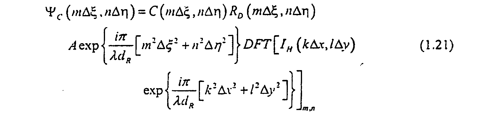
- The term "digital Fresnel hologram" is to be understood as meaning that the numerical reconstruction of the hologram can be performed using one of the algorithms described by Eqs. (1.18) or (1.21).
- As already mentioned, several reconstruction parameters 8 are required by the method for the numerical reconstruction of the hologram. With reference to FIGS. 4 and 5, three kinds of reconstruction parameters exist:
- The reconstruction distance d R 12 represents the distance between the hologram plane 0xy and the observation plane 0ξη. The adjustment of the value of d R allows to focus the reconstructed images. In order to obtain well focused reconstructed images, the value of the reconstruction distance must fit as well as possible the distance between the specimen and the plane where the hologram is created (for example we must have d R=d, with d as defined in FIG. 2A and in FIG. 3). If dielectric media are introduced between the specimen and the hologram, d R must fit the optical pathlength between the specimen and the hologram. It is understood that the optical path length is defined by the quotient between the real distance and the refractive index of the dielectric media. With a magnification (or demagnification) optics, the value of d R must fit the distance between the magnified (or demagnified) image and the plane where the hologram is created (for example we must have d R=d, with d as defined in FIGS. 6A to 6C).
- The adjustment of d R can be compared to the adjustment of the localisation in optical microscopy or in photography. In optical microscopy, the focalisation is performed by translating the specimen along the optical axis of the microscope. In photography, the specimen is fixed and the focalisation is performed by translating a lens along the optical axis of the imaging device. With the present invention, the same kind of operation can be performed digitally by adjusting the reconstruction distance d R. FIG. 7 shows three amplitude contrast images of a USAF test target obtained with different values of the reconstruction distance and is presented here in order to illustrate the effect of digital focusing associated to the adjustment of d R. FIG. 7A has been obtained for a too small value of d R, FIG. 7B for the correct value of d R and FIG. 7C for a too large value.
- It must be noticed, with reference to FIG. 3, that the sign of d R is important. If d R is positive the real image is in focus and if d R is negative, the observation plane is located behind the hologram and the twin image is in focus.
- The reference wave parameters 13 are two sets of reconstruction parameters; {p amp} for the definition of the amplitude and {p ph} for the definition of the phase of the digital reference wave. The number of elements in these sets depends on the analytical expression of the reference wave 15. A precise adjustment of the reference wave parameters which defines the phase of the digital reference wave ({p ph}) is important for quantitative phase contrast imaging. As explained above (see. Eq. (1.8) and related explications), the values of these parameters must be adjusted with precision in such a way that the wavefronts of the digital reference wave R D match as close as possible those of the experimental reference wave R (of those of its complex conjugate).
- The phase aberration function correction parameters 14 form a set of reconstruction parameters {p ab}. The number of element in this set depends on the analytical expression of the phase aberration function 16. A precise adjustment of the phase aberration function parameters is important for quantitative phase contrast imaging. The values of these parameters must be adjusted with precision in such a way that the multiplication of the reconstructed wavefront in the observation plane Ψ(mΔξ,nΔη) by the digital phase mask C (mΔξ,nΔη) corrects as well as possible the phase aberration functions in the observation plane.
- The expressions "fit as well as possible", "matches as close as possible" or "corrects as well as possible" are to be understood as meaning that the quality of the reconstructed images can be sufficient for a given application even if the reconstruction parameters are not exactly adjusted meaning that the computed digital reference wave and digital phase mask are not exact replica of their experimental equivalents. The same remark is also valid for the definition of the analytical expressions of the reference wave and of the phase aberration function. In other words, for the examples of the reconstruction distance and of the digital reference wave, the equalities d=d R and R D= R (digital reference wave = reference wave used for the hologram creation) are not strictly required to obtain a quantitative phase contrast image of the specimen but the required precision of this equality may vary from application to application, depending on the desired level of precision and image quality. The same kind of considerations is applicable to known situations in classical microscopy or in photography where, for example, the degree of precision of the focalisations of an image is limited by the quality of the optics and by the criteria (sometimes subjective) used to evaluate this focalisation. Of course, an exact (or nearly exact) adjustment of the reconstruction parameters and the definition of exact analytical expressions is achievable with the present invention but may require the use of sophisticated models for the definitions of the analytical expressions with an increasing number of reconstruction parameters and, as a consequence, an increase of the computation time.
- In a preferred manner, the adjustment of the reconstruction parameters which influence the quantitative phase contrast image (reference wave parameters and phase aberration function correction parameters) is performed using a an optically flat reference surface in and/or near or around the specimen. For example, this optically flat reference surface is a polished metallic or dielectric surface or a test pattern on which the specimen lies, typically a glass plate used as specimen holder as in classical microscopy. When such surface of known shape exists near the specimen, the reconstruction parameters can be adjusted in order to obtain the predicted phase distribution in the corresponding area of the reconstructed quantitative phase contrast image.. For example, the reconstruction parameters will be adjusted in order to obtain a constant phase distribution if the reference surface is planar. FIG. 8A shows an example of reconstructed quantitative phase contrast image of a biological cell on a glass plate. With this example, the reconstruction parameters have been adjusted in order to obtain a constant phase distribution around the cell where only the glass plate which is flat and planar participate to the image formation. The case where the specimen is not lying on a dielectric plate or on a mirror, but isolated in free space (supported, suspended or floating) can naturally also be considered.
- An illustration showing the effect a bad adjustment of the reference wave and phase aberration function correction parameters is shown in FIG. 8. For this example, a plane wave has been used for the hologram recording and a microscope objective has been used as magnification optics, with a geometrical arrangement as shown in FIG. 6A. In this case, the digital reference wave R D(kΔx,lΔy) is computed using Eq. (1.8) with the reference wave parameters A R, k x and k y and the digital phase mask C (mΔξ,nΔη)) is computed using Eqs. (1.10) and (1.11) with the phase aberration function correction parameter D. FIG. 8A shows the obtained quantitative phase contrast image with a correct adjustment of all reconstruction parameters (d R, D, k x , ky and A R.). The cell membrane, the nucleus and some intracellular structures are observable in this image. If the value of the phase aberration function correction parameter D is modified with respect to its correct value, the obtained quantitative phase contrast image which is shown in FIG. 8B. In this case, we observe that curved concentric fringes, which are characteristic of the quadratic phase aberration function of the microscope objective, appear on the image. These curved fringes appear when the phase difference between the computed digital phase mask C (mΔξ,nΔη)) and the complex conjugate of the phase aberration functions function of the microscope objective (experimental phase aberration function) is equal to a multiple of 2π. The value of D is adjusted in order to minimize the curvature of these fringes. If D is correctly adjusted, but the values of the reference wave parameter k x and k y are modified, we observe in FIG. 8C, that straight fringes with a fixed orientation and spacing appear on the obtained quantitative phase contrast image. These straight fringes appear when the phase difference between the wavefronts of R D(kΔx,lΔy) and the wavefronts of the experimental reference plane wave R (x,y) (or the wavefronts of its complex conjugate) is equal to a multiple of 2π. The values of k x and k y are adjusted in order to maximize the distance between two adjacent fringes. When no more fringes appear on the reconstructed images, a finer adjustment of k x and k y is performed in order to suppress residual constant gradients in the reconstructed phase distribution.
- If the reference wave is spherical (or nearly spherical), a bad adjustment of the reference wave parameters will produce curved fringes on the phase contrast image and the reference wave parameters are adjusted in order to eliminate these fringes. In this case a finer adjustment of the reconstruction parameters is performed in order to suppress residual constant curvatures of the reconstructed phase distribution.
- As shown in FIG. 9, four different procedures are possible for the adjustment of the correct values of the reconstruction parameters (a combination of these different procedures is also possible):
- A. Measurement of the reconstruction parameters: As the reconstruction parameters have a physical meaning (distances, angles, light intensities), their values can be measured on the set-up. This measurement can be performed by an apparatus which communicates with the computer. For example, in a set-up without magnification or demagnification optics the distance between the specimen and the plane where the hologram is created (d in FIG. 2A) can be measured and the obtained value can be used as reconstruction distance d R.
- B. Iterative adjustment: The adjustment of the reconstruction parameters can be performed iteratively by executing several times the numerical reconstruction of the same digital hologram in a loop. At the end of each iteration (each numerical reconstruction), the obtained amplitude and phase contrast images are analyzed and the values of the reconstruction parameters are modified. The reconstructed images obtained for this new set of reconstruction parameters are compared with the images obtained at the end of the previous iteration and the values of the reconstruction parameters are modified in order to improve the image quality. This loop is repeated until the values of the reconstruction parameters reach their optimal values. This operation can be performed by a human operator or automatically by a computer on the basis of a numerical method. For example, the adjustment of the reconstruction distance can be performed using an auto focus method which automatically maximize the high frequency content of the reconstructed image. Known focus criterion such as the so-called variation of intensity, sum modulus difference (SMD), entropy of gray levels or square plane sum modulus difference (SPSMD) can be used to evaluate quantitatively the localisation of the reconstructed images. The application of a Sobel or Prewitt filter to the reconstructed image followed by an integration can also be used as a focus criterion which must be maximized. Similar automatic methods can be used for the adjustment of the reference wave or phase aberration function correction parameters.
- C. Experimental adjustment: An other possibility is to perform the numerical reconstruction of the acquired digital holograms with fixed values of the reconstruction parameters and to modify the experimental configuration used for the hologram recording by translating and/or rotating the specimen and/or the components of the set-up. For example, the reconstruction of the digital hologram can be performed with a fixed value of the reconstruction distance d R and the specimen can be moved away from or closer to the plane where the hologram is created until the reconstructed images are in focus. If the experimental set-up comprises a magnification or a demagnification optics, the focalization of the reconstructed images can be performed as usually in classical microscopy or in classical photography by translating the specimen and/or the magnification or demagnification optics along the optical axis of the imaging system. If the reference wave is reflected by a mirror towards the plane where the hologram is created (as shown for example in FIGS. 2A and 2B), the adjustment the reference wave parameters can be performed by rotating and/or translating the mirror. If a magnification optics or a demagnification optics is used, as the phase aberration function in the observation plane depends generally on the distance between the specimen and the magnification optics, the adjustment of the phase aberration function parameters can be performed by translating the specimen and/or the magnification or demagnification optics along the optical axis of the imaging system. This experimental adjustment of the reconstruction parameters can be performed by a human operator or by an apparatus such as piezo-electric driven actuators or translators. If an apparatus is used and if this apparatus is controlled by a computer or by a processor, this experimental adjustment of the reconstruction parameters can be performed automatically using an iterative method. For example, focused images can be obtained using an auto focus method which controls the translation of the specimen or the translation of the magnification or demagnification optics.
- D. Analysis of the digital hologram: The hologram itself contains informations about the experimental configuration which has been used for the hologram creation and the digital hologram can be analyzed in order to estimate the values of the reconstruction parameters. For example, the digital hologram can be Fourier transformed and the distribution of spatial frequencies can be analyzed. In particular, if the hologram has been created in the off-axis geometry, the spatial frequencies are distributed principally at three different locations. The spatial frequencies corresponding to the non-interfering terms |R|2 and |O|2 (see Eq. (1.1)) are located in the center of the Fourier plane (low spatial frequencies) and the spatial frequencies corresponding to the interfering terms R*O and RO* (see Eq. (1.1)) are located at higher spatial frequencies, the position of which are related to the characteristics of the off-axis geometry. For example, if the hologram has been recorded in the off-axis geometry with a plane wave as reference, the values of the reference wave parameters k x and k y (see. Eq. (1.8)) can be estimated from the distribution of spatial frequencies in the Fourier domain.
-
- Generally, a first numerical reconstruction of the digital hologram is performed using a preliminary set of reconstruction parameters 19 with default values and the adjustment of the reconstruction parameters is performed using a combination of the procedures A, B, C and D as described above.
- The above mentioned methods for the adjustment of the reconstruction parameters assume that the digital reference wave and the digital phase mask are computed on the basis of known analytical expressions. An other possibility consists in evaluating the digital reference wave and the digital phase mask experimentally using a specimen of known phase distribution. For example, if an optically flat surface (e.g. a mirror) is used as specimen, a constant reconstructed phase distribution is attempted. If the numerical reconstruction of the hologram is performed without correction of the phase aberration function and without multiplication by a digital reference wave, the reconstructed phase distribution will be the result of three contributions: the attempted constant (specimen contribution), the phase aberration function (magnification optics contribution) and the phase of the reference wave in the observation plane (reference wave contribution). By subtraction of the constant contribution of the specimen, one can obtain the phase of both the digital reference wave and the digital phase mask. An array of complex numbers can be formed with this phase information and the multiplication of the obtained result by the complex conjugate of this array should allows one to recover the phase of the specimen.
- FIG. 10 shows six examples of numerical reconstruction of digital holograms and is presented here in order to clarify the idea of simultaneous amplitude and quantitative phase contrasts imaging. FIGS. 10A and 10B present respectively the amplitude contrast image and the quantitative phase contrast image of an USAF test target. The hologram has been recorded in the reflection geometry (the object wave is reflected by the specimen). The specimen (USAF test target) is composed of a glass plate on which rectangular reflective elements of several sizes are created by chromium evaporation. In amplitude contrast (FIG. 10A), the obtained image reveals changes of the reflectance of the specimen, and in quantitative phase contrast (FIG. 10B), the obtained image reveals changes of both the topography of the specimen and the optical phase shift at the reflection on the surface. Both amplitude and quantitative phase contrast images reveal the same pattern because the highest parts of the specimen are also the most reflective.
- FIGS. 10C and 10D present respectively the amplitude contrast image and the quantitative phase contrast image of a pure phase object. The hologram has been recorded in the reflection geometry. The specimen has been fabricated by evaporating a thin layer of aluminium (70 nm) over the surface of a USAF test target. In amplitude (FIG. 10C), no contrast is observable because the optical properties are the same over the whole surface of the specimen, and in quantitative phase contrast (FIG. 10D), the obtained image reveals exclusively the topography of the specimen.
- FIGS. 10E and 10F present respectively the amplitude contrast image and the quantitative phase contrast image of a biological cell. The hologram has been recorded in the transmission geometry (the object wave is created by the light that is transmitted by the specimen). As biological cells are almost transparent, the reconstructed image in amplitude contrast (FIG. 10E) reveals less details than the quantitative phase contrast image (FIG. 10F), the contrast of which is due to differences in the refractive index and/or in the thickness of the specimen.
- FIG. 11 is presented here in order to clarify the idea of quantitative phase contrast and shows an example of quantitative measurement performed with the present invention. FIG. 11A shows a view in a three-dimensional perspective of the phase contrast image presented in FIG. 10D. As the specimen is a pure phase object, the reconstructed phase distribution Φ(ξ,η) is directly proportional the height distribution h(ξ,η) on the sample surface (topography of the specimen):
- FIG. 11B is a graph to show an example of quantitative surface profilometry. A phase profile has been extracted from the data corresponding to the image presented in FIG. 11A. The measured phase values have been converted to height measurements using Eq. (1.22) and reported on the graph of FIG. 11B, the corresponding profile is referred as "Digital holography" and gives a measurement of about 55 nanometers (nm) for the step height. For comparison, the same step height has been measured by scanning a standard contact stylus probe profilometer (Alpha-step 500) over the corresponding area of the sample. As shown in FIG. 11B, both techniques are in excellent agreement.
- With the present invention, a set of holograms (at least two) of the same specimen or of several different specimens can be recorded, acquired, digitized and numerically reconstructed using the various above described methods. It is also clear that each individual hologram can be the hologram of many specimens at the same time or in other words that the specimen can be composed of several specimens.
- For example, this set of holograms can be a time sequence of holograms which have been created, with the same or with an other specimen, at different instants. The corresponding numerically reconstructed amplitude and/or quantitative phase contrast set of images represent then the specimen (or the different specimens) at these different instants and this set of reconstructed images can be used in order to build a computed video animation and/or in order to monitor a deformation of the specimen and/or a movement of the specimen and/or a modification of the optical properties of the specimen.
- For example, this set of holograms can contains holograms of the same specimen which have been recorded at the same instant using several image acquisition systems and an appropriate set-up. The corresponding reconstructed images represent the specimen with different direction of observations.
- For example, this set of holograms can contain holograms which have been created in the transmission geometry, for different orientations of a semi-transparent or transparent specimen. For example, the specimen can be rotated between each hologram acquisition. Then, the well-known Fourier slice theorem can be applied to the set of corresponding numerically reconstructed amplitude and/or quantitative phase contrast set of images which are considered as the projections of the specimen along the optical path way. Backprojections techniques are also appropriate for the reconstruction. In a more developed version of the method, diffraction tomography is a known approach which can be applied to the treatment of the set of reconstructed images in order to build a computed three-dimensional tomography of the specimen.
- An other method resulting from the present invention is based on the treatment of a set of holograms obtained after successive modifications of the irradiation wavelength λ. If the holograms are recorded in the transmission geometry with a semi transparent specimen, and provided that the dispersion law of the refractive index is known, the exact thickness of the specimen can be derived.
- An other method resulting from the present invention is based on the treatment of a set of holograms obtained after successive modifications of the irradiation wavelength λ. A computed three dimensional description of the specimen can be obtained from the Fourier transform of the set of corresponding reconstructed amplitude and quantitative phase contrast images regularly sampled at wavevectors kz obtained by changing the wavelength. If the set of holograms is recorded in the Fourier configuration, the three-dimensional reconstruction of the specimen can be performed using a three dimensional Fourier transform. If the set of holograms contains Fresnel holograms, the three-dimensional reconstruction of the specimen can be performed using Fourier transform along the direction of the optical axis and a Fresnel transform in the transverse planes.
- The present invention can also be used to reconstruct a hologram which results from the interference between an object wave and more than one reference waves. For example, the different reference waves can correspond to different off-axis configurations and the corresponding reconstructed images will appear at different locations of the observation plane.
- For example, the hologram can be created using two reference waves with crossed polarizations and with different directions of propagation. For example, a Wollaston prism can be used to perform this separation in direction and polarization. In this case, two reconstructed images corresponding to the crossed polarization can be observed separately and used to measure the birefringence and the dichroism of the specimen.
- The present invention can also be used to reconstruct a hologram which results from the interference between one reference wave and more than one object waves.
- The present invention can also be used to reconstruct a hologram which results from the interference between more than one reference wave and more than one object waves. In other words, the present invention can be applied to reconstruct a hologram which can be expressed as follow:where i and j are integers (i, j ≥ 1). The reconstruction of such holograms produces several images which can be reconstructed separately with different values of the reconstruction parameters.

- If the direction of propagation of the reference wave is changed synchronously with a modification of the object wavefront in a time sequence shorter than the hologram acquisition, time can be recorded.
- It is an other object of the present invention to propose a new method for interferogram analysis, or in other words, a method for analysing a hologram recorded using an imaging system which produce an image of the specimen which is focused on the CCD. In this case, the reconstruction method do not require a calculation of scalar diffraction. In standard optical interferometry, a commonly used method consists in analysing the interferogram using a Fourier method. The hologram is digitally Fourier transformed and the obtained two dimensional spectrum is spatially filtered in order to eliminate all spatial frequencies except those of one of the interference term R*O or RO*. The selected spatial frequencies are then translated to the center of the spectrum and the amplitude and the phase of the selected interference term can be obtained by calculating the inverse Fourier transform of the filtered spectrum. A drawback of these methods is that the obtained phase distribution is that of the product R*O or RO*. For this reason , in standard optical interferometry , phase unwrapping methods (which are often time consuming) are applied to eliminate the contribution of the reference wave in order to obtain the phase distribution of the object wave. We propose here to perform the same operation as the phase unwrapping method using a computed digital reference wave and a computed phase mask which multiply the complex field obtained after calculation of the inverse Fourier transform. In this case, the digital phase mask and the digital reference wave can also be adjusted using the methods described above.
- Figure 12 a illustrate an exemplary portion of a generalized computer system 500 upon which portions of the invention may be implemented. For example, the configurations illustrated in Figures 1-3 and 5-6 may each be implemented in a plurality of computers having a generalized configuration as exemplified by Figure 12a or by a plurality of computers having the configurations similar to those of Figures 12a and 12b described below.
- An input 502 of Figure 12a communicates with a memory 504 and a central processing unit 508. The central processing unit 508 communicates with the memory 504. The central processing unit 508 may include an arithmetic/logic unit and a control unit in the form of hardware and/or software (not shown). One or more inputs 502 may each be in communication with one or more memories 504 and /or central processing unit 508. One or more central processing unit 508 may be in communication with one or more outputs 506 and/or memories 504 and /or inputs 502. One or more memories 504 may be in communication with one or more inputs 502 and /or central processing unit 508 and /or outputs 506. Clearly, a plurality of variations of computer hardware configurations may be realized in a network of computers systems upon which portions of the invention may be implemented.
- Figure 12b illustrates an exemplary hardware configuration of a generalized computer system 520 upon which portions of the invention may be implemented. One or more processors 524 are connected to a communication bus 522. The communication bus 522 also communicates with a main memory 526, preferably a random access memory ("RAM"). A secondary memory 528 communicating with the communication bus 522 may also be included in the computer system 520. The secondary memory 528 may include, for example, a hard disk drive, a removable storage drive such as a floppy disk drive, a magnetic tape drive, an optical disk drive, a program cartridge and cartridge interface, a removable memory chip (e.g. EPROM, PROM, ROM), or any other similar storage medium. The secondary memory 528 may be in communication with a storage unit 530 such as a floppy disk, magnetic tape, optical disk, or others storage medium read by and written by a secondary memory device. The storage unit 530 includes a computer usable storage medium for storing computer software and date.
- The computer system 520 may also include a communication interface 532 in communication with the communication bus 522 for transferring software and data between the computer system 520 and external devices. Examples of communication interfaces 532 include a modem, a network interface(e.g. a network card), a communication port, a PCMCIA slot and card, and other similar interfaces. Software and data transferred via the communication interface 532 are in the form of signals 536 which are provided to the communication interface 532 via a channel 534. The signals 536 may be electronic, electromagnetic, optical, or other signals capable of being received by the communication interface 532. The channel 534 may be implemented using wire, cable, fiber optics, a phone line, a cellular phone link, a RF link, an IR link, or other communication channels.
- Computer programs are stored in main memory 526 and /or secondary memory 528. Computer programs may be received via the communication interface 532. Computer programs, when executed by the processor 524, enable the computer system 520 to perform the features of the present invention.
- The invention can be conveniently implemented using a network of conventional computer and/or microprocessors programmed according to the teachings of the present specification, as will be apparent to those skilled in the computer art from reading above descriptions regarding figures 1-12b. Appropriate software coding can be readily be prepared by skilled programmers based on the teachings of the present disclosure, as will be apparent to those skilled in the software art. The invention may also be implemented by the preparation of application specific integrated circuits or by interconnecting an appropriated network of conventional components circuits, as will be readily apparent to those skilled in the art.
- The present invention includes a computer program product which is a storage medium including the instructions which can be used to program a computer or a plurality of networked computers to perform a process of the invention. The storage medium can include but it is not limited to, any type of disks including floppy disks, optical disks, CD ROMs, and magneto-optical disks, ROMs, RAMs, EPROMs, EEPROMs, magnetic or optical cards of any type of media suitable for storing electronic instructions.
Claims (72)
- A method for simultaneous amplitude and quantitative phase contrast imaging of a specimen by numerical reconstruction of a digital hologram of the specimen, resulting from the interference of an object wave passing through a magnification or demagnification optics and a reference wave, and comprising the following steps:a) providing a hologram of the specimen using an illumination source;b) acquiring said hologram by an image acquisition system;c) digitizing said hologram by an image digitizer in order to produce a digital hologram;d) transmitting the digital hologram to a computer or to a processor;e) determining a digital reference wave based on the reference wave and a second group of reconstruction parameters as reference wave parameters;f) computing multiplication between the digital hologram and the digital reference wave in order to create a digital transmitted wavefront in a hologram plane;g) determining and defining a first group of reconstruction parameters as the reconstruction distance;h) computing of the propagation of the digital transmitted wavefront from the hologram plane to an observation plane in order to calculate the digital reconstructed wavefront in the observation plane wherein said computing is performed by a numerical calculation of an integral describing the diffraction of waves in the scalar approximation and wherein a distance between the hologram plane and the observation plane is defined by the reconstruction distance;i) determining a digital phase mask based on the phase aberration function and a third group of reconstruction parameters as phase aberration function correction parameters, wherein said phase aberration function represents the deformation of the wavefronts which travel across the magnification or demagnification optics;j) digitally correcting the phase aberration function by computation of the multiplication between the digital reconstructed wavefront in the observation plane and the digital phase mask in order to obtain the digital corrected reconstructed wavefront in the observation plane;k) computing the modulus or the square of the modulus of the digital corrected reconstructed wavefront in the observation plane in order to obtain an amplitude contrast image of the specimen;l) computing the argument of the digital corrected reconstructed wavefront in the observation plane in order to obtain a quantitative phase contrast image of the specimen;m)adjusting of the reconstruction parameters by performing iterative adjustment with a loop involving the iteration of the steps f), h), k), j) and l) leading to the determination of the precise reconstruction parameters.
- A method for simultaneous amplitude and quantitative phase contrast imaging of a specimen by numerical reconstruction of a digital hologram of the specimen, resulting from the interference of an object wave passing through a magnification or demagnification optics and a reference wave, and comprising the following steps:wherein each procedure A, B, C, D can be executed as a single procedure or in combination.a) providing a hologram of the specimen using an illumination source;b) acquiring said hologram by an image acquisition system;c) digitizing said hologram by an image digitizer in order to produce a digital hologram;d) transmitting the digital hologram to a computer or to a processor;e) determining and defining a first group of reconstruction parameters as the reconstruction distance;f) computing the function correction parameters digital reconstructed wavefront in the observation plane by computation of the diffraction pattern of the digital hologram, wherein said computing is performed by a numerical calculation of an integral describing the diffraction of waves in the scalar approximation and wherein a distance between the hologram plane and the observation plane is defined by the reconstruction distance;g) determining a digital reference wave based on the reference wave and a second group of reconstruction parameters as reference wave parameters;h) computing the multiplication between the digital reconstructed wavefront in the observation plane and the digital reference wave in order to correct the phase distortion induced by the reference wave in the observation plane;i) determining a digital phase mask based on the phase aberration function and a third group of reconstruction parameters as phase aberration function correction parameters wherein said phase aberration function represents the deformation of the wavefronts which travel across the magnification or demagnification optics;j) digitally correcting the phase aberration function by computation of the multiplication between the digital phase mask and the result of step h) in order H to obtain the digital corrected reconstructed wavefront in the observation plane;k) computing the modulus or the square of the modulus of the digital corrected reconstructed wavefront in the observation plane in order to obtain an amplitude contrast image of the specimen;l) computing the argument of the digital corrected reconstructed wavefront in the observation planes in order to obtain a quantitative phase contrast image of the specimen;m)adjusting the reconstruction parameters comprising :A. the measurement of the reconstruction parameters;B. the iterative adjustment where a loop involving the iteration of the steps f),h),j),k) and l) leading to the determination of the precise reconstruction parameters;C. the experimental adjustment of the reconstruction parameters;D. the analysis of the digital hologram in order to evaluate directly the reconstruction parameters;
- A method according to claim 1 or 2 wherein the step of determination of a digital reference wave comprises the step of measuring experimentally and digitalizing the reference wave, for example by using a reference mirror or a nanometric sized metallic bead.
- A method according to claim 1 or 2 wherein said digital phase mask is measured experimentally, for example by using a reference mirror or a nanometric sized metallic bead.
- A method according to claim 1 wherein the step of determination of a digital reference wave comprises the steps ofdetermining an analytical expression of a reference wave and determining and defining the second group of reconstruction parameters as reference wave parameters,computing by the computer of an array of complex numbers as a digital replica of the reference wave called digital reference wave, wherein said computing is performed on the basis of the analytical expression of the reference wave and on the basis of the reference wave parameters,
and wherein the step of determination of a digital phase mask comprises the steps ofdetermining and defining an analytical expression of the phase aberration function and determining and defining the third group of reconstruction parameters as phase aberration function correction parameters,computing an array of complex numbers called the digital phase mask which represents the complex conjugate of the phase aberration function in the observation plane, said computing being performed on the basis of the analytical expression of the phase aberration function and on the basis of the phase aberration function correction parameters. - A method according to claim 2 wherein the step of determination of a digital reference wave comprises the steps ofdetermining an analytical expression of a reference wave and determining and defining of the second group of reconstruction parameters as the reference wave parameters,computing an array of complex numbers as a digital replica of the reference wave called digital reference wave, wherein said computing is performed on the basis of an analytical expression of the reference wave and on the basis of the reference wave parameters,
and wherein the step of determination of a digital phase mask comprises the steps ofdetermining and defining an analytical expression of the phase aberration function and determining and defining the third group of reconstruction parameters as phase aberration function correction parameters,computing an array of complex numbers called the digital phase mask which represents the complex conjugate of the phase aberration function in the observation plane, said computing being performed on the basis of the analytical expression of the phase aberration function and on the basis of the phase aberration function correction parameters. - A method according to claim 6 wherein said reconstruction parameters are a set of constants which must be supplied to the program which executes the numerical reconstruction of the digital hologram and wherein said constants are supplied to the computer which executes the program by a human operator, for example on the basis of a previous adjustment, or by a measuring apparatus which communicates with the computer or by another program running on the same or on another computer.
- A method according to claim 5 or 6 comprising the application of digital image processing methods before and/or after the numerical reconstruction of the digital hologram wherein said image processing methods are applied, before said step e), to the digital hologram and/or after step k) and/or after step l) claims 1 and 2 to the said amplitude contrast image of the specimen and/or to the said phase contrast image.
- A method according to claim 5 or 6 wherein said hologram is provided by an off-axis hologram wherein the directions of propagation of the reference and object waves are not parallel at their incidence on the plane where the hologram is created whereby the acquisition and reconstruction of an off-axis hologram allows for the separation of the zero order of diffraction, the twin image and the real image which can be observed separately in the observation plane.
- A method according to claim 5 or 6 wherein said hologram is an off-axis hologram and wherein said digital hologram is processed, before said step e), by an image processing method comprising the steps of:computing the two dimensional discrete Fourier transform of the digital hologram;locating, in the Fourier transform of the digital hologram, the spatial frequencies which correspond to the interfering terms:computation of the multiplication of the Fourier transform of the hologram by a 2D function which eliminates or attenuates the spatial frequencies which do not correspond to the interfering terms;computing the discrete inverse Fourier transform.
- A method according to claim 5 or 6 wherein said hologram is spatially filtered by applying an optical method, including a combination of a non linear component and a 4-f system and a mask designed for high-pass filtering.
- A method according to claim 5 or 6 wherein said integral describing the diffraction of waves in the scalar approximation is one of a the Fresnel-Kirchhoff integral or a Rayleigh-Sommerfeld integral or an approximation of these integrals such as a Fresnel integral.
- A method according to claim 5 or 6 wherein said numerical calculation of an integral describing the diffraction of waves in the scalar approximation is performed by the numerical calculation of a discrete formulation of the Fresnel integral called the Fresnel transform and which is computed using the following equations:where, F(mΔξ,nΔη) denotes the discrete Fresnel transform of the discrete function f(kΔx,lΔy), F(mΔξ,nΔη) is an array of complex numbers, f(kΔx,lΔy) can be an array of complex numbers or an array of real or integer numbers, λ is the wavelength of the illumination source, d R is the reconstruction distance, A=exp(i2πdR /λ)l(iλd R ) is a complex constant and k,l,m,n are integers

- A method according to claim 5 or 6 wherein said hologram is provided by a set-up which provides a Fresnel hologram wherein the numerical calculation of an integral describing the diffraction of waves in the scalar approximation is performed by the numerical calculation of a Fresnel transform.
- A method according to claim 5 or 6 wherein said hologram is provided by a set-up which produces Fourier holograms and wherein said numerical calculation of an integral describing the diffraction of waves in the scalar approximation is performed by a Fourier transformation.
- A method according to claim 5 or 6 wherein said hologram of the specimen is created using a reference wave produced by means which allows for the adjustment of the length of the path of the reference wave.
- A method according to claims 5 or 6 wherein an object wave is produced by an assembly of optics components which produces a magnified or a demagnified image of the specimen.
- A method according to claims 5 or 6 wherein said step b) is performed by propagation of a replica of the hologram by one of the following optical means : a combination of one or more lenses and/or Hopkins relay optics used in an endoscope, and/or gradient index rods and/or optical fibers and/or bundles of optical fibers and/or multicore fibers.
- A method according to claim 5 or 6 wherein said image digitizer is used to transform the hologram in a form which can be transmitted to said computer or a processor.
- A method according to claim 5 or 6 wherein said analytical expression of the digital reference wave is computed as a two-dimensional function of complex numbers.
- A method according to claim 5 or 6 wherein said reference wave parameters are defined and used as parameters involved in the analytical expression of the reference wave and are necessary for the definition of the digital reference wave.
- A method according to claim 5 or 6 wherein said reference wave is a plane wave of a given wavelength λ, and the digital reference wave R D(kΔx,lΔy) can be computed using the following expression:where k x, k y and A R are the reference wave parameters, k x and k y are two real numbers which represent the components of the normalized wavevector defining the direction of propagation of the plane wave, A R is a real number which represents the amplitude of the reference wave, and Δx and Δy are the sampling intervals in the hologram plane.

- A method according to claim 5 or 6 wherein said reference wave is a spherical wave of a given wavelength λ, and the digital reference wave RD (kΔx,lΔy) can be computed using the following expression:where (xR, yR, zR) are the coordinates of the point source with respect to the centre of the hologram plane 0xy and A R is the amplitude at the point source.
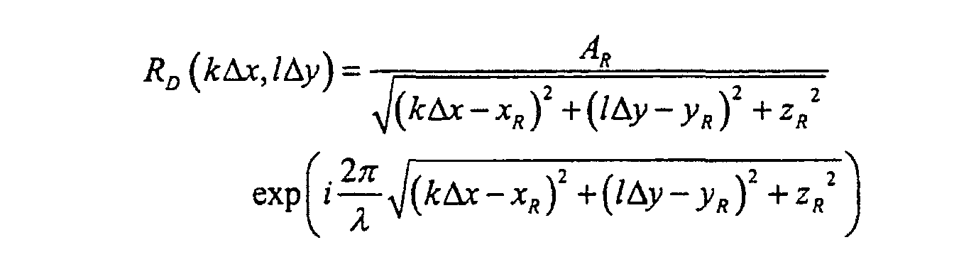
- A method according to claim 5 or 6 wherein said digital reference wave R D(kΔx,lΔy) is calculated using a combination of Zernike polynomials.
- A method according to claim 5 or 6 wherein the value of said reconstruction distance is adjusted in order to fit as well as possible the distance or the length of the optical path between the specimen and the plane where the hologram is created whereby " as well as possible" is being understood as following any one or all of the described procedures of adjustment of the reconstruction parameters.
- A method according to claims 5 or 6 wherein said object wave is provided by a magnification or a demagnification optics, and the value of said reconstruction distance is adjusted in order to fit as well as possible the distance between an image of the specimen and the plane where the hologram is created, whereby " as well as possible" is being understood as following any one or all of the procedures of adjustment of the reconstruction parameters.
- A method according to claims 5 or 6 wherein said object wave is provided by a magnification or a demagnification optics, and a phase distortion appears in the observation plane, and, as a consequence, said digital reconstructed wavefront in the observation plane must be corrected in order to allow for a corrected reconstruction of said quantitative phase contrast image of the specimen, whereby said analytical expression of the phase aberration function is a two-dimensional function of complex numbers in such a way that said digital phase mask matches as closely as possible the complex conjugate of the phase aberration function in the observation plane , and whereby " as close as possible" is being understood as following any one or all of the procedures of adjustment of the reconstruction parameters.
- A method according to claims 5 or 6 wherein said phase aberration function correction parameters are parameters which are involved in the analytical expression of the phase aberration function, whereby the phase aberration function correction parameters are adjusted in such a way that the multiplication of said reconstructed wavefront in the observation plane by said digital phase mask corrects as well as possible the phase aberration functions, including aberrations, in the observation plane, whereby "as well as possible" is being understood as following any one or all of the procedures of adjustment of the reconstruction parameters.
- A method according to claims 5 or 6 wherein said object wave is provided by a single spherical lens as magnification or demagnification optics, and said digital phase mask C(mΔξ,nΔη) can be computed using the following expression:where λ is the wavelength of the illumination source, Δξ and Δη are the sampling intervals in the observation plane, and D is the phase aberration function correction parameter which depends on the specimen-lens distance d o and on the lens-image distance d according to:


- A method according to claims 5 or 6 wherein said digital phase mask C(mΔξ,nΔη) is calculated using a combination of Zernike polynomials, whereby the phase aberration function correction parameters include the Zernike polynomial coefficients.
- A method according to claim 5 or 6 wherein said adjustment of the reconstruction parameters is performed in such a way as to reconstruct the real image of the specimen.
- A method according to claim 5 or 6 wherein said adjustment of the reconstruction parameters is performed in such a way as to reconstruct the twin image of the specimen.
- A method according to claim 5 or 6 wherein said adjustment of the reconstruction parameters is performed by measuring the associated physical quantities on the set-up used for the hologram creation, and wherein said measurement can be performed by an apparatus which communicates with the computer.
- A method according to claim 5 or 6 wherein said adjustment of the reconstruction parameters is performed iteratively by executing several times the numerical reconstruction of the same hologram in a loop and modifying the reconstruction parameters in order to improve the image quality and/or plausibility wherein said loop is repeated until the values of the reconstruction parameters have reached their values of convergence.
- A method according to claim 5 or 6 wherein said adjustment of the reconstruction parameters is performed by translating and/or rotating the specimen and/or components of the set-up used for the creation of the hologram.
- A method according to claim 5 or 6 wherein said adjustment of the reconstruction parameters is performed by analysing the digital hologram with a numerical method.
- A method according to claim 5 or 6 wherein said amplitude contrast image and quantitative phase contrast image are reconstructed simultaneously and are two different representations of the same specimen at the same instant.
- A method according to claim 5 or 6 wherein said quantitative phase contrast is computed and used for quantitative measurements of optical properties and/or structural information, for example, refractive index measurements or thickness measurements.
- A method according to claim 5 or 6 wherein, with the goal of establishing the topography of the specimen, the surface height is computed from the said quantitative phase contrast at each point of the surface of the specimen.
- A method according to claim 5 or 6 wherein, with the goal of establishing the profile of the surface of the specimen, the surface height is computed from the said quantitative phase contrast at each point of the line along which the profile is drawn.
- A method according to claim 5 or 6 wherein said image acquisition system provides real-time image acquisition and wherein the numerical reconstruction of the acquired digital holograms is performed instantaneously after the image acquisition in order to allow for real-time amplitude and quantitative phase contrast imaging.
- A method according to claim 5 or 6 wherein said illumination source is a low-coherence or a pulsed illumination source and wherein the hologram is created with the light that is reflected by a selected slice inside a semi-transparent specimen and wherein said reference wave is provided by means which allow for the adjustment of the length of the path of the reference wave, and thus provide means to select the depth of the slice.
- A method according to claim 5 or 6 wherein said object wave and said reference wave have the same wavelength in order to perform a homodyne detection of the hologram.
- A method according to claim 5 or 6 wherein at least one of said reference wave and said object wave are provided by means which modify at least one of the wavelength, and the amplitude, the frequency the polarization, the phase or the optical path length of the waves.
- A method according to claim 5 or 6 wherein at least one of said reference wave and said object wave are provided by means which produce different wavelengths or frequencies for the object wave and for the reference wave, in order to achieve a heterodyne detection of the hologram.
- A method according to claim 5 or 6 wherein said hologram is provided by a set-up which is designed to create an in-line or Gabor hologram.
- A method where a set of holograms of the same specimen are created, acquired and reconstructed according to the method of one of the independent claims 1 or 2.
- A method according to claim 47 wherein said set of holograms of the same specimen are recorded in a reflection geometry for different orientations of the specimen, and wherein the information contents of the reconstructed amplitude contrast images and quantitative phase contrast images, corresponding to the different orientations of the specimen, can be used in order to build a computed three-dimensional replica of the specimen.
- A method according to claim 47 wherein said set of holograms of the same specimen are recorded in a transmission geometry for different orientations of the specimen and wherein information contents of the reconstructed amplitude contrast images and quantitative phase contrast images, corresponding to the different orientations of the specimen can be used in order to build a three dimensional computed tomography of the specimen.
- A method according to claim 47 wherein said set of holograms of the same specimen are recorded for different wavelengths of the illumination source or with different illumination sources of different wavelengths and wherein the information content of the reconstructed amplitude contrast images and quantitative phase contrast images corresponding to the different wavelengths can be used for spectroscopic investigations of the three-dimensional specimen.
- A method according to claim 47 wherein said set of holograms of the same specimen are recorded for different wavelengths of the illumination source or with different illumination sources of different wavelengths and wherein the data corresponding to the different holograms are combined to yield a three dimensional conformation of the specimen by computing the 3D Fourier transform or the combined 1D Fourier - 2D Fresnel transform of the set of holograms.
- A method according to claim 47 wherein said specimen is semi-transparent and wherein said set of holograms of the same specimen are recorded in a transmission geometry for different wavelengths of the illumination source or with different illumination sources of different wavelengths and wherein a model describing the behaviour of the refractive index as a function of the wavelength is used in order to measure the three dimensional distribution of the refractive index and/or the thickness of the specimen, on the basis of the data corresponding to the different wavelengths.
- A method according to claim 47 wherein said set of holograms of the same specimen are recorded with different off-axis geometries, for example with different orientations of a mirror which reflects the reference wave, so that the reconstructed images will appear in different locations of the observation plane and represent the specimen at different instants.
- A method according to claim 47 wherein said set of holograms of the same specimen is recorded with different polarization states of the reference wave, for example with different orientation of a linearly polarized reference wave, and wherein reconstructed images corresponding to the different polarization states of the reference wave can be used to investigate the birefringence, the dichroism or the scattering behaviour of the specimen.
- A method according to claim 47 wherein said set of holograms of the same specimen is recorded at different instants and wherein reconstructed images corresponding to the different instants are used in order to build a computed video animation and to monitor a deformation of the specimen and to monitor a movement of the specimen and to monitor a modification of the optical properties of the specimen.
- A method according to claim 47 wherein said set of holograms is recorded at different instants with the same specimen which can be transformed over time, and wherein reconstructed images corresponding to the different instants are used in order to build a computed video animation.
- A method according to claim 47 wherein said set of holograms of the same specimen is recorded using several image acquisition systems and an appropriate set-up wherein corresponding reconstructed images represent the specimen with different directions of observations at different instants.
- A method according to claim 5 or 6 wherein said specimen includes several distinct objects located at different locations in a three dimensional volume.
- A method according to claim 5 or 6 wherein said hologram is created using a plurality of reference waves.
- A method according to claim 5 or 6 wherein said hologram is created using one reference wave and a plurality of object waves.
- A method according to claim 5 or 6 wherein said hologram is created using a plurality of reference waves and a plurality of object waves.
- A method according to claim 5 or 6 wherein said hologram is created using two reference waves of crossed polarizations and different directions of propagation and one object wave.
- A method according to claim 55 wherein said specimen includes several distinct objects located at different locations in a three dimensional volume.
- A method according to claim 47 wherein said specimen includes several distinct objects located at different locations in a three dimensional volume.
- A method according to claim 5 or 6 wherein said hologram is created using one reference wave and two object waves of crossed polarizations and different directions of propagation.
- A method according to claim 5 or 6 wherein said hologram is created using two reference waves of crossed polarization and different directions of propagation and two object waves of crossed polarization and different directions of propagation.
- A method according to claim 5 or 6 wherein a synchronized series of object waves interfere with a series of reference waves to form a single hologram, and wherein the reconstructed amplitude and phase contrast images yield the evolution in time of the object at different locations of the observation plane to allow for the study of the object changes under the modification of an external parameter in a rapid time sequence.
- A method according to claim 6 wherein said hologram is an off-axis hologram recorded with an image of the specimen focused on said image acquisition system and wherein said digital hologram can be processed before step e) by an image processing method comprising the steps of:Computing the two dimensional discrete Fourier transform of the digital hologram;Locating, in the Fourier transform of the digital hologram, the spatial frequencies which correspond to one of the interfering terms;Computation of the multiplication of the Fourier transform of the digital hologram by a 2D function which eliminates or attenuates all spatial frequencies except those of the selected interference term;Translating the spatial frequencies of the selected interference term to the center of the Fourier transform of the digital hologram;Computing the discrete inverse Fourier transform.
- A method according to claim 5 or 6 wherein said digital hologram is digitally processed before step e) to perform an apodization of its aperture in order to reduce the fluctuations of the amplitude or intensity and of the phase of the numerically reconstructed wavefront.
- Numerical Holographic Telescope or Digital Holographic Telescope for the simultaneous imaging of the amplitude and phase contrast of an objects comprising an illumination source, optical components guiding light from the at least one illumination source to the object and to at least one image detector or at least one camera, at least one image acquisition system and at least one image processing unit connected to said image acquisition system, the image acquisition system and the image processing unit being arranged to carry out the method of claims 1 to 69.
- Numerical Holographic Microscope or Digital Holographic Microscope for the simultaneous imaging of the amplitude and phase contrast of an object comprising an illumination source, optical components guiding light from the at least one illumination source to the object and to at least one image detector or at least one camera, at least one image acquisition system, and at least one image processing unit connected to said image acquisition system, the image acquisition system and the image processing unit being arranged to carry out the method of claims 1 to 69.
- Numerical Holographic Endoscope or Digital Holographic Endoscope for the simultaneous imaging of the amplitude and phase contrast of an object comprising an illumination source, optical components guiding light from the at least one illumination source to the object and to at least one image detector or at least one camera, at least one image acquisition system and at least one image processing unit connected to said image acquisition, the image acquisition system and the image processing unit being arranged to carry out the method of claims 1 to 69.
Applications Claiming Priority (5)
| Application Number | Priority Date | Filing Date | Title |
|---|---|---|---|
| US10355798P | 1998-10-07 | 1998-10-07 | |
| US103557P | 1998-10-07 | ||
| US265364 | 1999-03-10 | ||
| US09/265,364 US6262818B1 (en) | 1998-10-07 | 1999-03-10 | Method for simultaneous amplitude and quantitative phase contrast imaging by numerical reconstruction of digital holograms |
| PCT/CH1999/000477 WO2000020929A1 (en) | 1998-10-07 | 1999-10-07 | Method and apparatus for simultaneous amplitude and quantitative phase contrast imaging by numerical reconstruction of digital holograms |
Publications (2)
| Publication Number | Publication Date |
|---|---|
| EP1119798A1 EP1119798A1 (en) | 2001-08-01 |
| EP1119798B1 true EP1119798B1 (en) | 2005-03-09 |
Family
ID=26800598
Family Applications (1)
| Application Number | Title | Priority Date | Filing Date |
|---|---|---|---|
| EP99945836A Expired - Lifetime EP1119798B1 (en) | 1998-10-07 | 1999-10-07 | Method and apparatus for simultaneous amplitude and quantitative phase contrast imaging by numerical reconstruction of digital holograms |
Country Status (6)
| Country | Link |
|---|---|
| US (1) | US6262818B1 (en) |
| EP (1) | EP1119798B1 (en) |
| JP (1) | JP4772961B2 (en) |
| AT (1) | ATE290702T1 (en) |
| DE (1) | DE69924129T2 (en) |
| WO (1) | WO2000020929A1 (en) |
Cited By (6)
| Publication number | Priority date | Publication date | Assignee | Title |
|---|---|---|---|---|
| US7492871B2 (en) | 2006-02-01 | 2009-02-17 | Siemens Aktiengesellschaft | Focus/detector system of an x-ray apparatus for generating phase contrast recordings |
| US10127733B2 (en) | 2011-04-08 | 2018-11-13 | Nant Holdings Ip, Llc | Interference based augmented reality hosting platforms |
| US10140317B2 (en) | 2013-10-17 | 2018-11-27 | Nant Holdings Ip, Llc | Wide area augmented reality location-based services |
| US10401792B2 (en) | 2014-02-06 | 2019-09-03 | Lyncée Tec SA | Digital holographic device |
| US11340438B2 (en) | 2016-10-25 | 2022-05-24 | Lyncee Tec Sa | Fiber splitter device for digital holographic imaging and interferometry and optical system comprising said fiber splitter device |
| US12118581B2 (en) | 2011-11-21 | 2024-10-15 | Nant Holdings Ip, Llc | Location-based transaction fraud mitigation methods and systems |
Families Citing this family (149)
| Publication number | Priority date | Publication date | Assignee | Title |
|---|---|---|---|---|
| US6525821B1 (en) * | 1997-06-11 | 2003-02-25 | Ut-Battelle, L.L.C. | Acquisition and replay systems for direct-to-digital holography and holovision |
| US7127109B1 (en) * | 1999-09-27 | 2006-10-24 | University Of South Florida | Digital interference holographic microscope and methods |
| JP2001304816A (en) * | 2000-04-26 | 2001-10-31 | Kenichiro Kobayashi | Travel measuring system and apparatus using granular dot pattern by laser reflected light |
| JP3529705B2 (en) | 2000-06-14 | 2004-05-24 | 日本電信電話株式会社 | Hologram generation method and hologram information recording medium |
| US6882432B2 (en) * | 2000-08-08 | 2005-04-19 | Zygo Corporation | Frequency transform phase shifting interferometry |
| US6450960B1 (en) * | 2000-08-29 | 2002-09-17 | Barbara Ann Karmanos Cancer Institute | Real-time three-dimensional acoustoelectronic imaging and characterization of objects |
| US6849844B2 (en) * | 2000-10-12 | 2005-02-01 | Jed Khoury | 2-D microscopic tomographic systems utilizing 2-D deflection sensors |
| US6873733B2 (en) * | 2001-01-19 | 2005-03-29 | The Regents Of The University Of Colorado | Combined wavefront coding and amplitude contrast imaging systems |
| DE50112268D1 (en) * | 2001-02-09 | 2007-05-10 | Imaging Solutions Ag | Digital local image property control using masks |
| JP5103697B2 (en) * | 2001-04-19 | 2012-12-19 | 株式会社島津製作所 | 3D optical camera |
| US6525302B2 (en) * | 2001-06-06 | 2003-02-25 | The Regents Of The University Of Colorado | Wavefront coding phase contrast imaging systems |
| AU2002344849A1 (en) * | 2001-06-29 | 2003-03-03 | Universite Libre De Bruxelles | Method and device for obtaining a sample with three-dimensional microscopy |
| JP4782958B2 (en) * | 2001-09-21 | 2011-09-28 | 株式会社リコー | Surface shape measuring apparatus and method, program, and storage medium |
| WO2003048868A1 (en) * | 2001-12-04 | 2003-06-12 | Ecole Polytechnique Federale De Lausanne (Epfl) | Apparatus and method for digital holographic imaging |
| JP4137499B2 (en) * | 2002-04-23 | 2008-08-20 | 富士フイルム株式会社 | Phase information restoration method, phase information restoration device, and phase information restoration program |
| US7171031B2 (en) * | 2002-04-30 | 2007-01-30 | Fuji Photo Film Co., Ltd. | Method, apparatus, and program for restoring phase information |
| CA2436400A1 (en) * | 2002-07-30 | 2004-01-30 | Abel G. Wolman | Geometrization for pattern recognition, data analysis, data merging, and multiple criteria decision making |
| US6747771B2 (en) * | 2002-09-03 | 2004-06-08 | Ut-Battelle, L.L.C. | Off-axis illumination direct-to-digital holography |
| AU2003268404A1 (en) * | 2002-09-03 | 2004-03-29 | Ut-Battelle, Llc | Direct-to-digital off-axis holography with off-axis illuminated object |
| US6963406B2 (en) * | 2002-09-03 | 2005-11-08 | Ut-Battelle, Llc | Fused off-axis object illumination direct-to-digital holography with a plurality of illumination sources |
| US7038787B2 (en) * | 2002-09-03 | 2006-05-02 | Ut-Battelle, Llc | Content-based fused off-axis object illumination direct-to-digital holography |
| JP2005539256A (en) * | 2002-09-12 | 2005-12-22 | エヌライン、コーパレイシャン | System and method for detecting differences between composite images |
| AU2003272346A1 (en) * | 2002-09-12 | 2004-04-30 | Nline Corporation | Optical acquisition systems for direct-to-digital holography and holovision |
| US6809845B1 (en) * | 2002-09-25 | 2004-10-26 | University Of South Florida | Phase imaging using multi-wavelength digital holography |
| US7061625B1 (en) | 2002-09-27 | 2006-06-13 | Kla-Tencor Technologies Corporation | Method and apparatus using interferometric metrology for high aspect ratio inspection |
| US7095507B1 (en) | 2002-09-27 | 2006-08-22 | Kla-Tencor Technologies Corporation | Method and apparatus using microscopic and interferometric based detection |
| US7209239B2 (en) * | 2002-10-02 | 2007-04-24 | Kla-Tencor Technologies Corporation | System and method for coherent optical inspection |
| US7068375B2 (en) | 2003-01-23 | 2006-06-27 | Ut-Battelle Llc | Direct-to-digital holography reduction of reference hologram noise and fourier space smearing |
| FR2852409B1 (en) * | 2003-03-11 | 2005-06-17 | DEVICE FOR GENERATING A CARRIER IN AN INTERFEROGRAM | |
| WO2005003681A2 (en) * | 2003-04-23 | 2005-01-13 | Ut-Battelle, Llc | Faster processing of multiple spatially-heterodyned direct to digital holograms |
| US7312875B2 (en) * | 2003-04-23 | 2007-12-25 | Ut-Battelle Llc | Two-wavelength spatial-heterodyne holography |
| ITRM20030398A1 (en) * | 2003-08-13 | 2005-02-14 | Consiglio Nazionale Ricerche | METHOD FOR CHANGING THE SPATIAL RESOLUTION |
| DE10339227B4 (en) * | 2003-08-26 | 2014-05-28 | Byk Gardner Gmbh | Method and device for characterizing surfaces |
| US7119905B2 (en) * | 2003-08-26 | 2006-10-10 | Ut-Battelle Llc | Spatial-heterodyne interferometry for transmission (SHIFT) measurements |
| US6999178B2 (en) * | 2003-08-26 | 2006-02-14 | Ut-Battelle Llc | Spatial-heterodyne interferometry for reflection and transmission (SHIRT) measurements |
| AU2003290094A1 (en) | 2003-10-29 | 2005-06-08 | Asml Netherlands B.V. | Optical assembly for photolithography |
| FR2865538B1 (en) * | 2004-01-22 | 2007-10-19 | Centre Nat Rech Scient | DEVICE AND METHOD FOR MEASURING FRONT CONTRAST IN A MICHELSON INTERFEROMETER, AND EYE EXAMINATION SYSTEM INCLUDING SUCH A DEVICE |
| JP4069204B2 (en) * | 2004-03-16 | 2008-04-02 | 国立大学法人 和歌山大学 | Displacement distribution measurement method using digital holography |
| US7259869B2 (en) * | 2004-06-29 | 2007-08-21 | Kla-Tencor Technologies Corporation | System and method for performing bright field and dark field optical inspection |
| DE102004047531B4 (en) * | 2004-09-30 | 2006-07-13 | Kemper, Björn, Dr.rer.nat. | Interferometric simultaneous measurement of the topography and refractive index of the surface of an object by measuring the spatial phase distributions from both transmission and reflection interferograms |
| FR2879798B1 (en) * | 2004-12-20 | 2008-12-26 | Centre Nat Rech Scient Cnrse | HOLOGRAPHIC MEMORY WITH HOMODYNE DETECTION |
| JP2008526292A (en) * | 2004-12-30 | 2008-07-24 | ギブン イメージング リミテッド | Devices, systems and methods for optical in vivo analysis |
| US7633627B2 (en) * | 2005-01-20 | 2009-12-15 | Duke University | Methods, systems and computer program products for characterizing structures based on interferometric phase data |
| WO2006090320A1 (en) * | 2005-02-23 | 2006-08-31 | Lyncee Tec S.A. | Wave front sensing method and apparatus |
| KR100586026B1 (en) * | 2005-03-25 | 2006-06-02 | 한국전자통신연구원 | Digital hologram encoding and / or decoding device and method thereof |
| CN101147052B (en) * | 2005-03-25 | 2012-01-11 | 麻省理工学院 | System and method for Hilbert phase imaging |
| JP2006339364A (en) * | 2005-06-01 | 2006-12-14 | Toshiba Corp | Cleaning method and cleaning device |
| JP2007064864A (en) * | 2005-09-01 | 2007-03-15 | Toyo Seiki Seisakusho:Kk | Strain measuring method and device therefor |
| DE102007003681B4 (en) * | 2006-02-10 | 2017-11-30 | Hochschule Bremen | Method and device for analyzing an optical device |
| WO2007100823A2 (en) * | 2006-02-27 | 2007-09-07 | University Of Rochester | Phase contrast cone-beam ct imaging |
| EP2010885B1 (en) * | 2006-04-07 | 2020-06-03 | Ecole Polytechnique Fédérale de Lausanne | Method and apparatus to measure and compute the amplitude point spread function and associated parameters of a coherent optical imaging system |
| EP2033053A2 (en) * | 2006-06-09 | 2009-03-11 | Koninklijke Philips Electronics N.V. | Method and system for electroholographic display with zeroth-order diffraction suppression |
| DE102006030535A1 (en) * | 2006-06-28 | 2008-01-03 | Seereal Technologies S.A. | Method and device for generating reconstructions of information encoded in spatial light modulators |
| EP1914734B1 (en) * | 2006-10-13 | 2009-11-18 | Thomson Licensing | Holographic storage system with apodization filter |
| TW200818158A (en) * | 2006-10-13 | 2008-04-16 | Thomson Licensing | Holographic storage system with apodization filter |
| US7812959B1 (en) * | 2007-03-22 | 2010-10-12 | University Of South Florida | Total internal reflection holographic microscope |
| GB0718656D0 (en) * | 2007-05-16 | 2007-11-07 | Seereal Technologies Sa | Holograms |
| FR2917844A1 (en) * | 2007-06-20 | 2008-12-26 | Vincent Lauer | INTERFEROMETER DEVICE |
| US8194124B2 (en) * | 2007-10-09 | 2012-06-05 | Nanyang Technological University | In-line digital holographic microscope and a method of in-line digital holographic microscopy |
| TWI366749B (en) * | 2007-12-10 | 2012-06-21 | Ind Tech Res Inst | Multi-color off-axis digital holographic system and the imaging method thereof |
| US10426348B2 (en) | 2008-03-05 | 2019-10-01 | Purdue Research Foundation | Using differential time-frequency tissue-response spectroscopy to evaluate living body response to a drug |
| WO2009111609A2 (en) * | 2008-03-05 | 2009-09-11 | Purdue Research Foundation | Method and apparatus for motility contrast imaging |
| CN102067046A (en) * | 2008-06-19 | 2011-05-18 | 相位全息成像技术公司 | Analysis of transparent biological objects |
| USD608369S1 (en) * | 2008-06-19 | 2010-01-19 | Samsung Electronics Co., Ltd. | Transitional image for a mobile phone |
| CA2739017C (en) * | 2008-10-03 | 2016-03-22 | Universite Libre De Bruxelles | Holographic microscopy and method to investigate nano-sized objects |
| WO2010092533A1 (en) | 2009-02-13 | 2010-08-19 | Ecole Polytechnique Federale De Lausanne (Epfl) | Method and apparatus for 3d object shape and surface topology measurements by contour depth extraction acquired in a single shot |
| WO2010092739A1 (en) * | 2009-02-13 | 2010-08-19 | 国立大学法人京都工芸繊維大学 | Interference measuring device and interference measuring method |
| EP2401601B1 (en) | 2009-02-24 | 2021-09-22 | Lyncee Tec S.A. | Monitoring energy and matter fluxes by use of electromagnetic radiations |
| US20120116703A1 (en) | 2009-04-24 | 2012-05-10 | Nicolas Pavillon | Method and apparatus for enhanced spatial bandwidth wavefronts reconstructed from digital interferograms or holograms |
| US10498939B2 (en) * | 2009-06-16 | 2019-12-03 | Nri R&D Patent Licensing, Llc | Small-profile lensless optical microscopy imaging and tomography instruments and elements for low cost and integrated microscopy |
| EP2446251B1 (en) | 2009-06-25 | 2018-12-05 | Phase Holographic Imaging Phi AB | Analysis of ova or embryos with digital holographic imaging |
| US8363316B2 (en) * | 2009-08-21 | 2013-01-29 | Nanyang Technological University | Digital holographic microscopy |
| JP5552707B2 (en) * | 2009-11-06 | 2014-07-16 | 国立大学法人京都工芸繊維大学 | Reproducing apparatus, interference measuring apparatus, control program, and recording medium |
| TWI393871B (en) * | 2009-12-31 | 2013-04-21 | Metal Ind Res Anddevelopment Ct | Multi - wavelength Polarization Full - image Measurement System and Measurement Method |
| JP5352763B2 (en) * | 2010-01-22 | 2013-11-27 | 公立大学法人兵庫県立大学 | Complex amplitude in-line hologram generation method and image recording apparatus using the method |
| EP2534540B1 (en) * | 2010-02-09 | 2019-05-22 | Phase Holographic Imaging PHI AB | Method using digital holographic microscopy and imaging on labelled cell samples |
| WO2011106520A1 (en) | 2010-02-24 | 2011-09-01 | Ipplex Holdings Corporation | Augmented reality panorama supporting visually impaired individuals |
| WO2011121523A2 (en) * | 2010-03-28 | 2011-10-06 | Ecole Polytechnique Federale De Lausanne (Epfl) | Complex index refraction tomography with sub √6-resolution |
| JP5743419B2 (en) * | 2010-04-18 | 2015-07-01 | 国立大学法人宇都宮大学 | Shape measuring method and apparatus and strain measuring method and apparatus |
| DE102010029667A1 (en) * | 2010-06-02 | 2011-12-08 | Bremer Institut für angewandte Strahltechnik | Digital hologram generating method for detecting three-dimensional information from object, involves modulating reference wave by spatial light modulator such that digitally detected interference pattern represents digital hologram |
| EP3173769B1 (en) | 2010-08-20 | 2020-03-18 | Lyncee Tec Sa | Appartus and method for early diagnosis of cell death |
| US8428392B1 (en) * | 2010-09-08 | 2013-04-23 | Xiagen Feng | Systems and methods for measuring geometry parameters with a reference object whose thickness can not be ignored in images |
| JP5467321B2 (en) * | 2011-01-21 | 2014-04-09 | 公立大学法人兵庫県立大学 | 3D shape measuring method and 3D shape measuring apparatus |
| JP6460364B2 (en) | 2011-01-25 | 2019-01-30 | マサチューセッツ インスティテュート オブ テクノロジー | Off-axis reflection phase microscope system and method for off-axis phase microscope |
| EP2676173B1 (en) * | 2011-02-16 | 2023-03-29 | Phase Holographic Imaging Phi AB | Determination of physical parameters associated with erythrocytes |
| US9304490B2 (en) | 2011-05-27 | 2016-04-05 | Canon Kabushiki Kaisha | Apparatus and method for irradiating a medium |
| EP2535679A1 (en) | 2011-06-15 | 2012-12-19 | Lambda-X | Improvements in or relating to interferometry |
| EP2745265B1 (en) * | 2011-08-19 | 2018-07-18 | Koninklijke Philips N.V. | Frequency dependent combination of x-ray images of different modalities |
| EP2565725B1 (en) * | 2011-09-02 | 2014-04-30 | Mitutoyo Corporation | Method and apparatus for the exact reconstruction of the object wave in off-axis digital holography |
| WO2013047709A1 (en) * | 2011-09-30 | 2013-04-04 | ウシオ電機株式会社 | Digital holography method and digital holography device |
| WO2013086527A1 (en) | 2011-12-09 | 2013-06-13 | Massachusetts Institute Of Technology | Systems and methods self-referenced quantitative phase microscopy |
| WO2014044823A1 (en) | 2012-09-20 | 2014-03-27 | Ovizio Imaging Systems NV/SA | Digital holographic microscope with fluid systems |
| EP2951647B1 (en) * | 2012-09-25 | 2025-06-18 | Asociación centro de Investigación Cooperativa en Nanociencias, CIC Nanogune | Synthetic optical holography |
| US9057681B2 (en) * | 2012-12-07 | 2015-06-16 | The Regents Of The University Of California | High-temperature strain cell for tomographic imaging |
| US9364191B2 (en) | 2013-02-11 | 2016-06-14 | University Of Rochester | Method and apparatus of spectral differential phase-contrast cone-beam CT and hybrid cone-beam CT |
| TWI494716B (en) * | 2013-02-22 | 2015-08-01 | Univ Nat Central | Digital hologram imaging system and numerical reconstruction method for hologram |
| FR3002634B1 (en) * | 2013-02-28 | 2015-04-10 | Commissariat Energie Atomique | METHOD OF OBSERVING AT LEAST ONE OBJECT, SUCH AS A BIOLOGICAL ENTITY, AND ASSOCIATED IMAGING SYSTEM |
| US9135682B2 (en) * | 2013-03-15 | 2015-09-15 | Indian Institute Of Technology Delhi | Image recovery from single shot digital hologram |
| JP2015052663A (en) * | 2013-09-06 | 2015-03-19 | キヤノン株式会社 | Image processing method, image processing device, image-capturing device, and program |
| ES2534960B1 (en) | 2013-10-30 | 2016-02-09 | Universitat De València | Microscope, method and computer program for imaging quantitative phase by means of digital holographic microscopy, and kit to adapt an optical microscope |
| US9310767B2 (en) * | 2013-12-09 | 2016-04-12 | Consiglio Nazionale Delle Richerche-Cnr | Reconstruction of an image of an object at least partially hidden by a flame |
| DE102013113773B4 (en) * | 2013-12-10 | 2016-09-29 | RUHR-UNIVERSITäT BOCHUM | Method for the microscopic measurement of samples by means of short-coherent interferometry |
| FR3016056B1 (en) | 2013-12-31 | 2017-05-05 | Commissariat Energie Atomique | SYSTEM FOR ACQUIRING IMAGES BY DIGITAL HETERODYNE HOLOGRAPHY |
| EP2913683A1 (en) | 2014-02-26 | 2015-09-02 | Nuomedis AG | Method and apparatus for automated scanning probe microscopy |
| EP2998776A1 (en) * | 2014-09-22 | 2016-03-23 | Nanolive SA | Tomographic phase microscope |
| US10088662B2 (en) * | 2015-04-30 | 2018-10-02 | Farnoud KAZEMZADEH | System, method and apparatus for ultra-resolved ultra-wide field-of-view multispectral and hyperspectral holographic microscopy |
| WO2016177319A1 (en) | 2015-05-04 | 2016-11-10 | Versitech Limited | Apparatus and method for quantitative phase-gradient chirped-wavelength-encoded optical imaging |
| KR101681311B1 (en) * | 2015-06-30 | 2016-12-01 | 연세대학교 산학협력단 | Aberration Compensation Method for Microoptic Devices using Pattern Recognition |
| EP3196631A1 (en) | 2016-01-19 | 2017-07-26 | Ovizio Imaging Systems NV/SA | Digital holographic microscope with electro-fluidic system, said electro-fluidic system and methods of use |
| FR3049348B1 (en) * | 2016-03-23 | 2023-08-11 | Commissariat Energie Atomique | METHOD FOR CHARACTERIZING A PARTICLE IN A SAMPLE |
| EP3252455A1 (en) * | 2016-05-30 | 2017-12-06 | Biomérieux | Device and method for acquiring a particle present in a sample |
| GB2551150B (en) | 2016-06-06 | 2020-07-01 | Cursor Controls Ltd | Trackballs |
| WO2017221330A1 (en) * | 2016-06-21 | 2017-12-28 | オリンパス株式会社 | Digital holographic image pickup device and sample holder |
| US10378963B2 (en) | 2016-06-24 | 2019-08-13 | Ushio Denki Kabushiki Kaisha | Optical system phase acquisition method and optical system evaluation method |
| US10365164B2 (en) | 2016-07-20 | 2019-07-30 | Ushio Denki Kabushiki Kaisha | Optical system phase acquisition method and optical system evaluation method |
| KR101868882B1 (en) * | 2016-09-28 | 2018-06-19 | 광운대학교 산학협력단 | Device for obtaining hologram image using reflected light and apparatus for restructuring shape of object with the device |
| KR101865330B1 (en) * | 2017-01-19 | 2018-06-07 | 충북대학교 산학협력단 | Method for measuring and analysis optical property of hologram and system thereof |
| WO2018211345A1 (en) | 2017-05-15 | 2018-11-22 | Ecole Polytechnique Federale De Lausanne (Epfl) | Holographic device or imager |
| TWI648604B (en) | 2017-12-27 | 2019-01-21 | 財團法人工業技術研究院 | Digital direct imaging method and system, image generation method and electronic device |
| US10416609B1 (en) * | 2018-03-07 | 2019-09-17 | The Government Of The United States Of America As Represented By The Secretary Of The Air Force | Single shot imaging using digital holography receiver |
| EP3575773A1 (en) * | 2018-05-28 | 2019-12-04 | Universität für Bodenkultur Wien | A method for determining a three-dimensional particle distribution in a medium |
| KR102036640B1 (en) * | 2018-06-15 | 2019-10-25 | 고려대학교 산학협력단 | Optical imaging method capable of high-speed correction of optical aberration |
| CN109581645B (en) | 2018-11-22 | 2020-07-24 | 南京理工大学 | Phase contrast and differential interference phase contrast microscopic imaging method based on light intensity transmission equation |
| WO2020117864A1 (en) * | 2018-12-04 | 2020-06-11 | The Regents Of The University Of California | Portable uv holographic microscope for high-contrast protein crystal imaging |
| KR102150110B1 (en) * | 2018-12-12 | 2020-08-31 | 주식회사 내일해 | Method for generating 3d shape information of an object |
| WO2020154812A1 (en) | 2019-02-01 | 2020-08-06 | UNIVERSITé LAVAL | System and method for determining a refractive index of a medium |
| WO2020174266A1 (en) | 2019-02-28 | 2020-09-03 | Lyncee Tec Sa | Imaging system for imaging in a controlled environment |
| FR3097337B1 (en) * | 2019-06-13 | 2021-07-23 | Commissariat Energie Atomique | Acousto-optical imaging system |
| JP7156190B2 (en) * | 2019-07-05 | 2022-10-19 | 株式会社島津製作所 | Cell observation device |
| KR102845457B1 (en) * | 2019-09-18 | 2025-08-11 | 삼성전자주식회사 | Super resolution holographic microscope |
| WO2021064807A1 (en) | 2019-09-30 | 2021-04-08 | 株式会社ニコン | Microscope device, data generation method, and program |
| KR102361669B1 (en) * | 2019-10-23 | 2022-02-11 | 세종대학교 산학협력단 | Flying-over beam pattern scanning hologram microscopy |
| US11782385B2 (en) * | 2019-12-17 | 2023-10-10 | Fei Company | Reconstruction algorithms of electron-based holograms |
| DE102020101994B4 (en) | 2020-01-28 | 2023-12-21 | Fraunhofer-Gesellschaft zur Förderung der angewandten Technik e.V. | Method and device for lensless imaging using Fourier transform holography |
| DE102020113159A1 (en) * | 2020-05-14 | 2021-11-18 | Carl Zeiss Ag | Method and system for measuring a surface topography of an object |
| CN115812138A (en) | 2020-07-12 | 2023-03-17 | 奥宝科技有限公司 | Systems and methods for reconstruction of digital holograms |
| US20230324275A1 (en) * | 2020-08-07 | 2023-10-12 | The Regents Of The University Of California | A simple in-line digital holography system for measuring 3d cell shape |
| KR102247277B1 (en) * | 2020-08-25 | 2021-05-03 | 주식회사 내일해 | Method for generating 3d shape information of an object |
| KR102612045B1 (en) * | 2020-11-02 | 2023-12-12 | 한국전자통신연구원 | Method for operating digital hologram displaying device |
| TR202020477A2 (en) * | 2020-12-14 | 2021-01-21 | Dokuz Eyluel Ueniversitesi Rektoerluegue | A DIGITAL HOLOGRAM IMAGING DEVICE WITH ACOUSTIC MODULE |
| FR3118499B1 (en) * | 2020-12-28 | 2024-02-23 | Commissariat Energie Atomique | Method of forming a complex image of a sample |
| CN113223142B (en) * | 2021-04-12 | 2022-10-04 | 浙江大学 | Improved gray-scale chromatographic reconstruction method for realizing plankton three-dimensional imaging |
| KR102455591B1 (en) * | 2021-12-07 | 2022-10-19 | 재단법인 구미전자정보기술원 | Apparatus for outputting multi light |
| KR102586647B1 (en) * | 2021-12-13 | 2023-10-10 | 한국전자기술연구원 | Holographic optical element printing method using focus tunable lens and rotating mirror |
| CN114237000B (en) * | 2021-12-15 | 2023-05-23 | 中国工程物理研究院激光聚变研究中心 | Off-axis digital holographic optimization reconstruction method and system |
| CN115078413B (en) * | 2022-06-30 | 2023-05-05 | 广西大学 | Novel phase-shift electroholography based on transmission electron microscope |
| CN116339098B (en) * | 2023-02-28 | 2025-12-05 | 浙江理工大学 | A method for eliminating and reconstructing zero-order terms in light off-axis digital holography with reference light symmetry deflection |
| CN116205111B (en) * | 2023-03-09 | 2024-01-16 | 北京理工大学 | Optimization method of multi-dimensional multi-channel multiplexed metasurface holography based on reverse design |
| KR102763946B1 (en) * | 2023-04-19 | 2025-02-07 | 한국표준과학연구원 | A numerical phase-detection autofocusing method for digital holography reconstruction processing |
Citations (1)
| Publication number | Priority date | Publication date | Assignee | Title |
|---|---|---|---|---|
| EP0307029A1 (en) * | 1987-09-03 | 1989-03-15 | Koninklijke Philips Electronics N.V. | Apparatus for the point-by-point scanning of an object |
Family Cites Families (2)
| Publication number | Priority date | Publication date | Assignee | Title |
|---|---|---|---|---|
| US5214581A (en) * | 1990-01-17 | 1993-05-25 | Rhodes Charles K | Method for object reconstruction from x-ray holograms |
| JP4035668B2 (en) * | 1996-06-10 | 2008-01-23 | 富士ゼロックス株式会社 | Image processing apparatus, image processing method, and storage medium |
-
1999
- 1999-03-10 US US09/265,364 patent/US6262818B1/en not_active Expired - Fee Related
- 1999-10-07 JP JP2000574990A patent/JP4772961B2/en not_active Expired - Lifetime
- 1999-10-07 DE DE69924129T patent/DE69924129T2/en not_active Expired - Lifetime
- 1999-10-07 WO PCT/CH1999/000477 patent/WO2000020929A1/en not_active Ceased
- 1999-10-07 EP EP99945836A patent/EP1119798B1/en not_active Expired - Lifetime
- 1999-10-07 AT AT99945836T patent/ATE290702T1/en not_active IP Right Cessation
Patent Citations (1)
| Publication number | Priority date | Publication date | Assignee | Title |
|---|---|---|---|---|
| EP0307029A1 (en) * | 1987-09-03 | 1989-03-15 | Koninklijke Philips Electronics N.V. | Apparatus for the point-by-point scanning of an object |
Non-Patent Citations (2)
| Title |
|---|
| CUCHE E. ET AL: "Tomographie oprique par une technique d'holographie numeriqueen faible coherence", NOUVELLE REVUE D'OPTIQUE, vol. 28, 1997, pages 260 - 264, XP000857144 * |
| GOODMANN J.: "Introduction to Fourier optics", 1996, MCGRAW HILL, pages: 99 - 120 * |
Cited By (17)
| Publication number | Priority date | Publication date | Assignee | Title |
|---|---|---|---|---|
| US7492871B2 (en) | 2006-02-01 | 2009-02-17 | Siemens Aktiengesellschaft | Focus/detector system of an x-ray apparatus for generating phase contrast recordings |
| DE102006017291B4 (en) * | 2006-02-01 | 2017-05-24 | Paul Scherer Institut | Focus / detector system of an X-ray apparatus for producing phase contrast recordings, X-ray system with such a focus / detector system and associated storage medium and method |
| US11107289B2 (en) | 2011-04-08 | 2021-08-31 | Nant Holdings Ip, Llc | Interference based augmented reality hosting platforms |
| US11514652B2 (en) | 2011-04-08 | 2022-11-29 | Nant Holdings Ip, Llc | Interference based augmented reality hosting platforms |
| US10403051B2 (en) | 2011-04-08 | 2019-09-03 | Nant Holdings Ip, Llc | Interference based augmented reality hosting platforms |
| US11967034B2 (en) | 2011-04-08 | 2024-04-23 | Nant Holdings Ip, Llc | Augmented reality object management system |
| US10726632B2 (en) | 2011-04-08 | 2020-07-28 | Nant Holdings Ip, Llc | Interference based augmented reality hosting platforms |
| US10127733B2 (en) | 2011-04-08 | 2018-11-13 | Nant Holdings Ip, Llc | Interference based augmented reality hosting platforms |
| US11869160B2 (en) | 2011-04-08 | 2024-01-09 | Nant Holdings Ip, Llc | Interference based augmented reality hosting platforms |
| US11854153B2 (en) | 2011-04-08 | 2023-12-26 | Nant Holdings Ip, Llc | Interference based augmented reality hosting platforms |
| US12118581B2 (en) | 2011-11-21 | 2024-10-15 | Nant Holdings Ip, Llc | Location-based transaction fraud mitigation methods and systems |
| US10664518B2 (en) | 2013-10-17 | 2020-05-26 | Nant Holdings Ip, Llc | Wide area augmented reality location-based services |
| US11392636B2 (en) | 2013-10-17 | 2022-07-19 | Nant Holdings Ip, Llc | Augmented reality position-based service, methods, and systems |
| US10140317B2 (en) | 2013-10-17 | 2018-11-27 | Nant Holdings Ip, Llc | Wide area augmented reality location-based services |
| US12008719B2 (en) | 2013-10-17 | 2024-06-11 | Nant Holdings Ip, Llc | Wide area augmented reality location-based services |
| US10401792B2 (en) | 2014-02-06 | 2019-09-03 | Lyncée Tec SA | Digital holographic device |
| US11340438B2 (en) | 2016-10-25 | 2022-05-24 | Lyncee Tec Sa | Fiber splitter device for digital holographic imaging and interferometry and optical system comprising said fiber splitter device |
Also Published As
| Publication number | Publication date |
|---|---|
| DE69924129T2 (en) | 2006-05-04 |
| JP2002526815A (en) | 2002-08-20 |
| DE69924129D1 (en) | 2005-04-14 |
| JP4772961B2 (en) | 2011-09-14 |
| ATE290702T1 (en) | 2005-03-15 |
| US6262818B1 (en) | 2001-07-17 |
| EP1119798A1 (en) | 2001-08-01 |
| WO2000020929A1 (en) | 2000-04-13 |
Similar Documents
| Publication | Publication Date | Title |
|---|---|---|
| US6262818B1 (en) | Method for simultaneous amplitude and quantitative phase contrast imaging by numerical reconstruction of digital holograms | |
| TWI797377B (en) | Surface shape measuring device and surface shape measuring method | |
| Zhou et al. | A review of the dual-wavelength technique for phase imaging and 3D topography | |
| US11644791B2 (en) | Holographic imaging device and data processing method therefor | |
| US7649160B2 (en) | Wave front sensing method and apparatus | |
| US7486406B2 (en) | Variable tomographic scanning with wavelength scanning digital interface holography | |
| EP2010885B1 (en) | Method and apparatus to measure and compute the amplitude point spread function and associated parameters of a coherent optical imaging system | |
| EP1631788B1 (en) | Digital holographic microscope for 3d imaging and process using it | |
| US7127109B1 (en) | Digital interference holographic microscope and methods | |
| US20170023472A1 (en) | Apparatus and method for quantitive phase tomography through linear scanning with coherent and non-coherent detection | |
| Palacios et al. | 3D image reconstruction of transparent microscopic objects using digital holography | |
| JP7352292B2 (en) | Holographic imaging device and holographic imaging method | |
| JP7723988B2 (en) | Optical measurement system and optical measurement method | |
| De Angelis et al. | Digital-holography refractive-index-profile measurement of phase gratings | |
| Kim et al. | Digital holography and multi-wavelength interference techniques | |
| WO2001023965A1 (en) | Digital interference holographic microscope and methods | |
| TWI923654B (en) | Optical Measurement System and Optical Measurement Method | |
| Nehmetallah et al. | Latest Advances in Single and Multiwavelength Digital Holography and Holographic | |
| Martinez-Leon et al. | Short-coherence digital holography for the investigation of 3D microscopic samples | |
| Kebbel et al. | New approach for testing of aspherical micro-optics with high numerical aperture | |
| Yan | Studies on resolution of digital holography system | |
| Singh et al. | Characterisation of laser marks using digital holographic microscopy | |
| Williams | Digital Holography for three dimensional tomographic and topographic measurements | |
| Cuche et al. | Phase contrast microscopy with digital holography | |
| ASimple | ANALOGIC AND NEURAL COMPUTING LABORATORY COMPUTER AND AUTOMATION INSTITUTE HUNGARIAN ACADEMY OF SCIENCES |
Legal Events
| Date | Code | Title | Description |
|---|---|---|---|
| PUAI | Public reference made under article 153(3) epc to a published international application that has entered the european phase |
Free format text: ORIGINAL CODE: 0009012 |
|
| 17P | Request for examination filed |
Effective date: 20010424 |
|
| AK | Designated contracting states |
Kind code of ref document: A1 Designated state(s): AT BE CH CY DE DK ES FI FR GB GR IE IT LI LU MC NL PT SE |
|
| 17Q | First examination report despatched |
Effective date: 20010906 |
|
| GRAP | Despatch of communication of intention to grant a patent |
Free format text: ORIGINAL CODE: EPIDOSNIGR1 |
|
| GRAS | Grant fee paid |
Free format text: ORIGINAL CODE: EPIDOSNIGR3 |
|
| GRAA | (expected) grant |
Free format text: ORIGINAL CODE: 0009210 |
|
| AK | Designated contracting states |
Kind code of ref document: B1 Designated state(s): AT BE CH CY DE DK ES FI FR GB GR IE IT LI LU MC NL PT SE |
|
| PG25 | Lapsed in a contracting state [announced via postgrant information from national office to epo] |
Ref country code: FI Free format text: LAPSE BECAUSE OF FAILURE TO SUBMIT A TRANSLATION OF THE DESCRIPTION OR TO PAY THE FEE WITHIN THE PRESCRIBED TIME-LIMIT Effective date: 20050309 Ref country code: AT Free format text: LAPSE BECAUSE OF FAILURE TO SUBMIT A TRANSLATION OF THE DESCRIPTION OR TO PAY THE FEE WITHIN THE PRESCRIBED TIME-LIMIT Effective date: 20050309 |
|
| REG | Reference to a national code |
Ref country code: GB Ref legal event code: FG4D |
|
| REG | Reference to a national code |
Ref country code: CH Ref legal event code: EP |
|
| REG | Reference to a national code |
Ref country code: IE Ref legal event code: FG4D |
|
| REF | Corresponds to: |
Ref document number: 69924129 Country of ref document: DE Date of ref document: 20050414 Kind code of ref document: P |
|
| REG | Reference to a national code |
Ref country code: CH Ref legal event code: NV Representative=s name: ANDRE ROLAND CONSEILS EN PROPRIETE INTELLECTUELLE |
|
| PG25 | Lapsed in a contracting state [announced via postgrant information from national office to epo] |
Ref country code: GR Free format text: LAPSE BECAUSE OF FAILURE TO SUBMIT A TRANSLATION OF THE DESCRIPTION OR TO PAY THE FEE WITHIN THE PRESCRIBED TIME-LIMIT Effective date: 20050609 Ref country code: DK Free format text: LAPSE BECAUSE OF FAILURE TO SUBMIT A TRANSLATION OF THE DESCRIPTION OR TO PAY THE FEE WITHIN THE PRESCRIBED TIME-LIMIT Effective date: 20050609 |
|
| PG25 | Lapsed in a contracting state [announced via postgrant information from national office to epo] |
Ref country code: ES Free format text: LAPSE BECAUSE OF FAILURE TO SUBMIT A TRANSLATION OF THE DESCRIPTION OR TO PAY THE FEE WITHIN THE PRESCRIBED TIME-LIMIT Effective date: 20050620 |
|
| REG | Reference to a national code |
Ref country code: SE Ref legal event code: TRGR |
|
| PG25 | Lapsed in a contracting state [announced via postgrant information from national office to epo] |
Ref country code: PT Free format text: LAPSE BECAUSE OF FAILURE TO SUBMIT A TRANSLATION OF THE DESCRIPTION OR TO PAY THE FEE WITHIN THE PRESCRIBED TIME-LIMIT Effective date: 20050907 |
|
| PG25 | Lapsed in a contracting state [announced via postgrant information from national office to epo] |
Ref country code: IE Free format text: LAPSE BECAUSE OF NON-PAYMENT OF DUE FEES Effective date: 20051007 Ref country code: CY Free format text: LAPSE BECAUSE OF FAILURE TO SUBMIT A TRANSLATION OF THE DESCRIPTION OR TO PAY THE FEE WITHIN THE PRESCRIBED TIME-LIMIT Effective date: 20051007 |
|
| PG25 | Lapsed in a contracting state [announced via postgrant information from national office to epo] |
Ref country code: MC Free format text: LAPSE BECAUSE OF NON-PAYMENT OF DUE FEES Effective date: 20051031 Ref country code: LU Free format text: LAPSE BECAUSE OF NON-PAYMENT OF DUE FEES Effective date: 20051031 |
|
| PLBE | No opposition filed within time limit |
Free format text: ORIGINAL CODE: 0009261 |
|
| STAA | Information on the status of an ep patent application or granted ep patent |
Free format text: STATUS: NO OPPOSITION FILED WITHIN TIME LIMIT |
|
| ET | Fr: translation filed | ||
| 26N | No opposition filed |
Effective date: 20051212 |
|
| REG | Reference to a national code |
Ref country code: IE Ref legal event code: MM4A |
|
| REG | Reference to a national code |
Ref country code: CH Ref legal event code: PCAR Free format text: ANDRE ROLAND S.A.;CASE POSTALE 5107;1002 LAUSANNE (CH) |
|
| REG | Reference to a national code |
Ref country code: FR Ref legal event code: PLFP Year of fee payment: 17 |
|
| REG | Reference to a national code |
Ref country code: FR Ref legal event code: PLFP Year of fee payment: 18 |
|
| REG | Reference to a national code |
Ref country code: FR Ref legal event code: PLFP Year of fee payment: 19 |
|
| REG | Reference to a national code |
Ref country code: FR Ref legal event code: PLFP Year of fee payment: 20 |
|
| PGFP | Annual fee paid to national office [announced via postgrant information from national office to epo] |
Ref country code: NL Payment date: 20181019 Year of fee payment: 20 |
|
| PGFP | Annual fee paid to national office [announced via postgrant information from national office to epo] |
Ref country code: DE Payment date: 20181019 Year of fee payment: 20 Ref country code: SE Payment date: 20181019 Year of fee payment: 20 |
|
| PGFP | Annual fee paid to national office [announced via postgrant information from national office to epo] |
Ref country code: IT Payment date: 20181024 Year of fee payment: 20 Ref country code: GB Payment date: 20181019 Year of fee payment: 20 Ref country code: CH Payment date: 20181019 Year of fee payment: 20 Ref country code: BE Payment date: 20181019 Year of fee payment: 20 Ref country code: FR Payment date: 20181022 Year of fee payment: 20 |
|
| REG | Reference to a national code |
Ref country code: DE Ref legal event code: R071 Ref document number: 69924129 Country of ref document: DE |
|
| REG | Reference to a national code |
Ref country code: NL Ref legal event code: MK Effective date: 20191006 |
|
| REG | Reference to a national code |
Ref country code: CH Ref legal event code: PL |
|
| REG | Reference to a national code |
Ref country code: GB Ref legal event code: PE20 Expiry date: 20191006 |
|
| REG | Reference to a national code |
Ref country code: BE Ref legal event code: MK Effective date: 20191007 |
|
| REG | Reference to a national code |
Ref country code: SE Ref legal event code: EUG |
|
| PG25 | Lapsed in a contracting state [announced via postgrant information from national office to epo] |
Ref country code: GB Free format text: LAPSE BECAUSE OF EXPIRATION OF PROTECTION Effective date: 20191006 |