EP1119706B1 - System, in particular for motor vehicle for starting a heat engine and for charging an electric circuit - Google Patents
System, in particular for motor vehicle for starting a heat engine and for charging an electric circuit Download PDFInfo
- Publication number
- EP1119706B1 EP1119706B1 EP00956618A EP00956618A EP1119706B1 EP 1119706 B1 EP1119706 B1 EP 1119706B1 EP 00956618 A EP00956618 A EP 00956618A EP 00956618 A EP00956618 A EP 00956618A EP 1119706 B1 EP1119706 B1 EP 1119706B1
- Authority
- EP
- European Patent Office
- Prior art keywords
- starter
- complementary
- electrical machine
- main electrical
- condition
- Prior art date
- Legal status (The legal status is an assumption and is not a legal conclusion. Google has not performed a legal analysis and makes no representation as to the accuracy of the status listed.)
- Expired - Lifetime
Links
Images

Classifications
-
- F—MECHANICAL ENGINEERING; LIGHTING; HEATING; WEAPONS; BLASTING
- F02—COMBUSTION ENGINES; HOT-GAS OR COMBUSTION-PRODUCT ENGINE PLANTS
- F02N—STARTING OF COMBUSTION ENGINES; STARTING AIDS FOR SUCH ENGINES, NOT OTHERWISE PROVIDED FOR
- F02N11/00—Starting of engines by means of electric motors
- F02N11/006—Starting of engines by means of electric motors using a plurality of electric motors
-
- F—MECHANICAL ENGINEERING; LIGHTING; HEATING; WEAPONS; BLASTING
- F02—COMBUSTION ENGINES; HOT-GAS OR COMBUSTION-PRODUCT ENGINE PLANTS
- F02N—STARTING OF COMBUSTION ENGINES; STARTING AIDS FOR SUCH ENGINES, NOT OTHERWISE PROVIDED FOR
- F02N11/00—Starting of engines by means of electric motors
- F02N11/04—Starting of engines by means of electric motors the motors being associated with current generators
-
- F—MECHANICAL ENGINEERING; LIGHTING; HEATING; WEAPONS; BLASTING
- F02—COMBUSTION ENGINES; HOT-GAS OR COMBUSTION-PRODUCT ENGINE PLANTS
- F02N—STARTING OF COMBUSTION ENGINES; STARTING AIDS FOR SUCH ENGINES, NOT OTHERWISE PROVIDED FOR
- F02N11/00—Starting of engines by means of electric motors
- F02N11/08—Circuits or control means specially adapted for starting of engines
- F02N11/0814—Circuits or control means specially adapted for starting of engines comprising means for controlling automatic idle-start-stop
-
- Y—GENERAL TAGGING OF NEW TECHNOLOGICAL DEVELOPMENTS; GENERAL TAGGING OF CROSS-SECTIONAL TECHNOLOGIES SPANNING OVER SEVERAL SECTIONS OF THE IPC; TECHNICAL SUBJECTS COVERED BY FORMER USPC CROSS-REFERENCE ART COLLECTIONS [XRACs] AND DIGESTS
- Y02—TECHNOLOGIES OR APPLICATIONS FOR MITIGATION OR ADAPTATION AGAINST CLIMATE CHANGE
- Y02T—CLIMATE CHANGE MITIGATION TECHNOLOGIES RELATED TO TRANSPORTATION
- Y02T10/00—Road transport of goods or passengers
- Y02T10/10—Internal combustion engine [ICE] based vehicles
- Y02T10/40—Engine management systems
Definitions
- the present invention relates to systems, in particular for vehicles which, on the one hand, start a combustion engine and on the other hand part of charging an electrical circuit.
- engine launch thermal is achieved by a starter, while charging the battery and consumer power is provided by an alternator.
- alternator-starter A such an electric machine that performs both functions at the same time is commonly referred to as the alternator-starter.
- this machine is arranged in place of the alternator. In electric motor mode, it drives the crankshaft pulley by means of the belt also used in generator mode.
- alternator-starter of separate type as opposed to alternator-starter machines which drive the engine directly by means of a meshing pinion with a gear crown.
- the separate starters-alternators present in operation in motor mode some disadvantages.
- the heat engine has a significant resistive torque that can prevent a satisfactory drive by the belt.
- this document relates to a system, particularly for motor vehicle, able to ensure on the one hand the starting of an engine thermal and on the other hand the loading of an electric circuit, comprising a main electric machine capable of functioning on the one hand as a generator and on the other hand as an electric motor, said electric machine driving the thermal engine by means of a belt when operating in engine mode electrical system, the system further comprising management means which control the main electric machine.
- Said system is such that it comprises a starter complementary to the engine, as well as detection means for detecting at least one triggering the activation of said complementary starter and the management means control in a particular sequence the machine main power and the starter when said condition is detected by said detection means.
- the system comprises complementary starting means (the starter), which when a condition requiring their activation is detected, complete the main electrical machine, according to a synchronized operation with that of said machine.
- the system of the aforementioned type is characterized the detection means comprise means for detecting an absence of starting at the end of a given time during which the main electric machine operates in electric motor mode.
- the invention also relates to a method for controlling a system, in particular for a motor vehicle, capable of ensuring on the one hand Starting a heat engine and secondly charging a circuit electrical system, comprising a main electric machine capable of operating a part as a generator and secondly as an electric motor, said machine electric motor driving the heat engine by means of a belt when operates in electric motor mode, said system comprising a starter complementary to the heat engine in which at least one triggering the activation of said complementary starter and command in a particular sequence the main electric machine and the starter when said condition is detected.
- This method is characterized in that to detect a condition of trigger, we detect a lack of start at the end of a given time during which the main electric machine operates in motor mode.
- said management module 9 is powered by the voltage of the battery, referenced B, to which it is connected via a switch 10 contact of the vehicle.
- the output it supplies the inductor of the alternator-starter 1, as well as the starter 5 and generates the voltages injected on the grids (A, B, C; A ', B', C ') of the transistors of the bridge 8.
- FIGS. 2a and 2b illustrate three power supply sequences of the alternator-starter 1 and starter 5 corresponding to three cases of operation different. These three feeding sequences have been referenced by I, II and III.
- Sequence I corresponds to the diet that is used when is detected that the engine and the starter system are in extreme operating conditions.
- the detection of extreme conditions is done by means of, for example, one or several temperature sensors (not shown in FIG. 1) connected to the management module 9, the latter implementing a comparison of the temperatures measured at one or more given thresholds.
- the threshold (s) are example functions of the characteristics of the internal combustion engine.
- the management module 9 controls the alternator-starter 1 and the starter 5 according to the following sequence.
- phase [1] in FIG. 2 the starter 5 is powered. Its drive gear moves and meshes on the crown toothed 6 of the transmission of the engine.
- the management module 9 command the power supply of the alternator-starter and the starter 5 as follows (sequence II).
- the module 9 supplies the inductor of the alternator-starter 1 so that it operates in electric motor mode, while the starter 5 is not requested (Phase 1]).
- alternator-starter 1 and starter 5 power supply is managed according to sequence III.
- the alternator-starter 1 is initially controlled in motor mode electrical (phase [1]); when the launch of the internal combustion engine is detected, we switch to generator mode (phase [2]). The starter 5 is not to him not activated.
Landscapes
- Engineering & Computer Science (AREA)
- Chemical & Material Sciences (AREA)
- Combustion & Propulsion (AREA)
- Mechanical Engineering (AREA)
- General Engineering & Computer Science (AREA)
- Control Of Vehicle Engines Or Engines For Specific Uses (AREA)
- Control Of Eletrric Generators (AREA)
- Combined Controls Of Internal Combustion Engines (AREA)
- Connection Of Motors, Electrical Generators, Mechanical Devices, And The Like (AREA)
Abstract
Description
La présente invention est relative aux systèmes, notamment pour véhicule automobile, qui assurent d'une part le démarrage d'un moteur thermique et d'autre part la mise en charge d'un circuit électrique.The present invention relates to systems, in particular for vehicles which, on the one hand, start a combustion engine and on the other hand part of charging an electrical circuit.
Elle concerne également la commande d'un tel système.It also relates to the control of such a system.
Habituellement, sur les véhicules automobiles, le lancement du moteur thermique est réalisé par un démarreur, tandis que la charge de la batterie et l'alimentation des consommateurs sont assurées par un alternateur.Usually on motor vehicles, engine launch thermal is achieved by a starter, while charging the battery and consumer power is provided by an alternator.
Il a déjà été proposé de réaliser ces deux fonctions au moyen d'un alternateur utilisé à la fois comme générateur et comme moteur électrique. Une telle machine électrique qui réalise à la fois les deux fonctions est couramment désignée sous le nom d'alterno-démarreur.It has already been proposed to carry out these two functions by means of a alternator used both as a generator and as an electric motor. A such an electric machine that performs both functions at the same time is commonly referred to as the alternator-starter.
Pour une présentation d'une telle machine, on pourra avantageusement se
référer au brevet FR 2 745 444.For a presentation of such a machine, it will be advantageous to
refer to
Généralement, cette machine est disposée à la place de l'alternateur. En mode moteur électrique, elle entraíne la poulie du vilebrequin au moyen de la courroie également utilisée en mode générateur. On parle alors d'un alterno-démarreur de type séparé, par opposition à des machines alterno-démarreurs qui entraíneraient directement le moteur thermique au moyen d'un pignon engrenant avec une couronne d'engrenage.Generally, this machine is arranged in place of the alternator. In electric motor mode, it drives the crankshaft pulley by means of the belt also used in generator mode. We then speak of an alternator-starter of separate type as opposed to alternator-starter machines which drive the engine directly by means of a meshing pinion with a gear crown.
Les alterno-démarreurs de type séparé présentent en fonctionnement en mode moteur certains inconvénients.The separate starters-alternators present in operation in motor mode some disadvantages.
Notamment, dans certaines conditions extrêmes, notamment à basse température, le moteur thermique présente un couple résistif important qui peut empêcher un entraínement satisfaisant par la courroie.In particular, under certain extreme conditions, especially at low temperature, the heat engine has a significant resistive torque that can prevent a satisfactory drive by the belt.
Egalement, les alterno-démarreurs séparés ne permettent pas des démarrages rapides dans tous les cas. Les temps de démarrage peuvent être relativement longs, notamment si le moteur thermique connaít des problèmes d'injection ou encore du fait du glissement de la courroie, etc..Separate alternator-starters also do not allow quick starts in all cases. Startup times can be relatively long, especially if the engine has problems injection or because of the slipping of the belt, etc.
Or, il est souhaitable que le démarrage d'un véhicule puisse se réaliser en des temps relativement courts, en particulier lorsque le calculateur de bord du véhicule met en oeuvre pour le moteur thermique un fonctionnement à coupure et redémarrage automatiques du moteur thermique lors des arrêts du véhicule (fonctionnement de type « stop & go » selon la terminologie anglo-saxonne classiquement utilisée par l'homme du métier). However, it is desirable that the starting of a vehicle can be realized in relatively short times, especially when the onboard computer of the vehicle implements for the engine a cut-off operation and automatic restart of the engine during vehicle stops (operation of the type "stop & go" according to the English terminology conventionally used by those skilled in the art).
On a proposé dans le document EP-A- 1 046 811, publié le 25/10/200 et
conforme au préambule des revendications 1 et 6, un système de démarrage et de
charge et une commande qui permettent de pallier ces inconvénients.It has been proposed in EP-A-1 046 811, published on 25/10/2002 and
in accordance with the preamble of
Plus particulièrement, ce document concerne un système, notamment pour véhicule automobile, apte à assurer d'une part le démarrage d'un moteur thermique et d'autre part la mise en charge d'un circuit électrique, comportant une machine électrique principale apte à fonctionner d'une part comme générateur et d'autre part comme un moteur électrique, ladite machine électrique entraínant le moteur thermique au moyen d'une courroie lorsqu'elle fonctionne en mode moteur électrique, le système comportant en outre des moyens de gestion qui commandent la machine électrique principale.More particularly, this document relates to a system, particularly for motor vehicle, able to ensure on the one hand the starting of an engine thermal and on the other hand the loading of an electric circuit, comprising a main electric machine capable of functioning on the one hand as a generator and on the other hand as an electric motor, said electric machine driving the thermal engine by means of a belt when operating in engine mode electrical system, the system further comprising management means which control the main electric machine.
Ledit système est tel qu'il comporte un démarreur complémentaire du moteur thermique, ainsi que des moyens de détection pour détecter au moins une condition de déclenchement de l'activation dudit démarreur complémentaire et les moyens de gestion commandent selon une séquence particulière la machine électrique principale et le démarreur lorsque ladite condition est détectée par lesdits moyens de détection.Said system is such that it comprises a starter complementary to the engine, as well as detection means for detecting at least one triggering the activation of said complementary starter and the management means control in a particular sequence the machine main power and the starter when said condition is detected by said detection means.
Ainsi, le système comporte des moyens de démarrage complémentaires (le démarreur), qui lorsqu'une condition nécessitant leur activation est détectée, complète la machine électrique principale, selon un fonctionnement synchronisé avec celui de ladite machine.Thus, the system comprises complementary starting means (the starter), which when a condition requiring their activation is detected, complete the main electrical machine, according to a synchronized operation with that of said machine.
Il peut être souhaitable de réduire encore le temps de démarrage du
moteur thermique.
Selon l'invention le système du type précité est caractérisé les moyens de
détection comportent des moyens pour détecter une absence de démarrage à
l'issue d'un temps donné pendant lequel la machine électrique principale
fonctionne en mode moteur électrique.It may be desirable to further reduce the starting time of the engine.
According to the invention the system of the aforementioned type is characterized the detection means comprise means for detecting an absence of starting at the end of a given time during which the main electric machine operates in electric motor mode.
Un tel système est en outre avantageusement complété par les différentes caractéristiques suivantes prises seules ou selon toutes leurs combinaisons techniquement possibles :
- les moyens de gestion comportent des moyens pour arrêter l'alimentation de la machine électrique principale puis alimenter le démarreur complémentaire lorsque le moteur thermique n'a pas démarré à l'issue du temps donné
- lesdits moyens de détection comportent au moins un capteur de température, ainsi que des moyens pour comparer une température mesurée par ledit capteur à un seuil inférieur particulier.
- les moyens de gestion comportent des moyens pour, lorsqu'une condition de l'activation du démarreur complémentaire est détectée, actionner le démarreur complémentaire de façon à ce que son pignon engrène sur une couronne complémentaire pour entraíner le moteur thermique, puis pour commander la machine électrique principale en mode moteur électrique, lorsque l'engrènement du pignon du démarreur est assuré et pour couper le démarreur et commander la machine électrique principale en mode générateur lorsqu'il est détecté que le moteur thermique est lancé.
- les moyens de gestion comportent des moyens pour couper le fonctionnement en mode moteur électrique de la machine électrique principale, lorsqu'une condition de l'activation du démarreur complémentaire est détectée.
- the management means comprise means for stopping the power supply of the main electric machine and then supplying the complementary starter when the heat engine has not started at the end of the given time
- said detection means comprise at least one temperature sensor, as well as means for comparing a temperature measured by said sensor with a particular lower threshold.
- the management means comprise means for, when a condition of activation of the complementary starter is detected, actuate the complementary starter so that its pinion meshes with a complementary ring to drive the engine, then to control the machine main electric motor mode, when the meshing of the starter gear is ensured and to cut the starter and control the main electric machine in generator mode when it is detected that the engine is launched.
- the management means comprise means for interrupting the electric motor mode operation of the main electric machine, when a condition of activation of the complementary starter is detected.
L'invention concerne également un procédé pour la commande d'un système, notamment pour véhicule automobile, apte à assurer d'une part le démarrage d'un moteur thermique et d'autre part la mise en charge d'un circuit électrique, comportant une machine électrique principale apte à fonctionner d'une part comme générateur et d'autre part comme un moteur électrique, ladite machine électrique entraínant le moteur thermique au moyen d'une courroie lorsqu'elle fonctionne en mode moteur électrique, ledit système comportant un démarreur complémentaire du moteur thermique dans lequel on détecte au moins une condition de déclenchement de l'activation dudit démarreur complémentaire et on commande selon une séquence particulière la machine électrique principale et le démarreur lorsque ladite condition est détectée.The invention also relates to a method for controlling a system, in particular for a motor vehicle, capable of ensuring on the one hand Starting a heat engine and secondly charging a circuit electrical system, comprising a main electric machine capable of operating a part as a generator and secondly as an electric motor, said machine electric motor driving the heat engine by means of a belt when operates in electric motor mode, said system comprising a starter complementary to the heat engine in which at least one triggering the activation of said complementary starter and command in a particular sequence the main electric machine and the starter when said condition is detected.
Ce procédé est caractérisé en ce que pour détecter une condition de déclenchement, on détecte une absence de démarrage à l'issue d'un temps donné pendant lequel la machine électrique principale fonctionne en mode moteur.This method is characterized in that to detect a condition of trigger, we detect a lack of start at the end of a given time during which the main electric machine operates in motor mode.
Un tel procédé est avantageusement complété par les différentes. caractéristiques suivantes prises seules ou selon toutes leurs combinaisons techniquement possibles :
- on arrête l'alimentation de la machine électrique principale, puis on alimente le démarreur complémentaire lorsque le moteur thermique n'a pas démarré à l'issue du temps donné.
- pour détecter une condition de déclenchement, on mesure au moins une température et on compare une température ainsi mesurée à un seuil inférieur particulier.
- lorsqu'une condition de l'activation du démarreur complémentaire est détectée, on actionne le démarreur complémentaire de façon à ce que son pignon engrène sur une couronne complémentaire pour entraíner le moteur thermique, puis on commande la machine électrique principale en mode moteur électrique, lorsque l'engrènement du pignon du démarreur est assuré et on coupe le démarreur et on commande la machine électrique principale en mode générateur lorsqu'il est détecté que le moteur thermique est lancé.
- on coupe le fonctionnement en mode moteur électrique de la machine électrique principale, lorsqu'une condition de l'activation du démarreur complémentaire est détectée.
- the power supply to the main electrical machine is stopped, and then the complementary starter is supplied when the heat engine has not started at the end of the given time.
- to detect a triggering condition, at least one temperature is measured and a temperature thus measured is compared to a particular lower threshold.
- when a condition of activation of the complementary starter is detected, the complementary starter is actuated so that its pinion meshes with a complementary ring gear to drive the heat engine, then the main electric machine is controlled in electric motor mode, when the meshing of the starter gear is ensured and the starter is cut and the main electrical machine is controlled in generator mode when it is detected that the engine is running.
- the operation in the electric motor mode of the main electric machine is cut off when a condition of activation of the complementary starter is detected.
D'autres caractéristiques et avantages de l'invention ressortiront encore de la description qui suit qui est purement illustrative et non limitative et qui doit être lue en regard des dessins annexés sur lesquels:
- la figure 1 est un schéma illustrant un système conforme à un mode de réalisation possible de l'invention ;
- les figures 2a et 2b sont des graphes temporels sur lesquels on a porté des exemples de séquences d'alimentation possibles pour l'alterno-démarreur et le démarreur complémentaire du système de la figure 1.
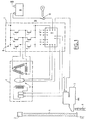
- Le système de démarrage et de charge illustré sur la figure 1 est composé :
- d'un alterno-démarreur séparé 1 dont l'arbre se termine par une
poulie 2 qui est reliée à unepoulie 3 du vilebrequin d'un moteur thermique par l'intermédiaire d'une courroie multi-gorges 4 ; cet alterno-démarreur est monté à la place que prend habituellement l'alternateur ; d'un démarreur 5 de complément, dont le pignon est apte à engrener la denture d'une couronne dentée 6 pour entraíner l'arbre du moteur thermique ;- d'une électronique de pilotage 7.
- Figure 1 is a diagram illustrating a system according to a possible embodiment of the invention;
- FIGS. 2a and 2b are time graphs on which examples of possible power supply sequences for the alternator-starter and the complementary starter of the system of FIG. 1 are given.
- The starting and charging system illustrated in Figure 1 is composed of:
- a separate alternator-
starter 1 whose shaft ends with apulley 2 which is connected to apulley 3 of the crankshaft of a heat engine via amulti-groove belt 4; this alternator-starter is mounted in the place that usually takes the alternator; - a
starter 5 of complement, whose pinion is adapted to mesh the toothing of a ring gear 6 to drive the shaft of the engine; - of a control electronics 7.
L'électronique de pilotage 7 est constituée :
- d'un pont de transistors 8 qui constitue un convertisseur de puissance réversible et qui assure le pilotage en mode démarreur et le redressement synchrone en mode alternateur.
- d'un module de gestion 9 qui commande les différents transistors du
convertisseur 8 et gère les différentes fonctions suivantes :
- puissance en modes démarreur et alternateur
- régulation en mode alternateur
- transition du mode démarreur au mode alternateur
- stratégie de fonctionnement pour les conditions extrêmes
- synchronisation des deux machines.
- a transistors bridge 8 which constitutes a reversible power converter and which provides control in starter mode and synchronous rectification in alternator mode.
- a management module 9 which controls the different transistors of the converter 8 and manages the following different functions:
- power in starter and alternator modes
- regulation in alternator mode
- transition from starter mode to alternator mode
- operating strategy for extreme conditions
- synchronization of the two machines.
Ledit module de gestion 9 est à cet effet alimenté par la tension de la
batterie, référencée par B, à laquelle il est relié par l'intermédiaire d'un interrupteur
10 de contact du véhicule.For this purpose, said management module 9 is powered by the voltage of the
battery, referenced B, to which it is connected via a
Il reçoit en entrée des informations lui permettant de déterminer la position
angulaire du rotor de l'alletmo-démarreur 1, par exemple des informations fournies
par des capteurs 11, tels que des capteurs à effet Hall 11.It receives as input information to determine the position
angular rotor of the alletmo-
En sortie, il alimente l'inducteur de l'alterno-démarreur 1, ainsi que le
démarreur 5 et génère les tensions injectées sur les grilles (A, B, C ; A', B', C') des
transistors du pont 8.At the output, it supplies the inductor of the alternator-
Les figures 2a et 2b illustrent trois séquences d'alimentation de l'alterno-démarreur
1 et du démarreur 5 correspondant à trois cas de fonctionnement
différents. Ces trois séquences d'alimentation ont été référencées par I, II et III.Figures 2a and 2b illustrate three power supply sequences of the alternator-
La séquence I correspond à l'alimentation qui est mise en oeuvre lorsqu'il est détecté que le moteur thermique et le système de démarrage se trouvent dans des conditions extrêmes de fonctionnement.Sequence I corresponds to the diet that is used when is detected that the engine and the starter system are in extreme operating conditions.
La détection de conditions extrêmes se fait au moyen par exemple d'un ou plusieurs capteurs de température (non représentés sur la figure 1) reliés au module de gestion 9, ce dernier mettant en oeuvre une comparaison de la ou les températures mesurées à un ou plusieurs seuils donnés. Le ou les seuils sont par exemple fonctions des caractéristiques du moteur à combustion interne.The detection of extreme conditions is done by means of, for example, one or several temperature sensors (not shown in FIG. 1) connected to the management module 9, the latter implementing a comparison of the temperatures measured at one or more given thresholds. The threshold (s) are example functions of the characteristics of the internal combustion engine.
Lorsque ces conditions de fonctionnement extrêmes sont détectées, le
module de gestion 9 commande alors l'alterno-démarreur 1 et le démarreur 5 selon
la séquence suivante. When these extreme operating conditions are detected, the
management module 9 then controls the alternator-
Dans une première phase (phase [1] sur la figure 2), le démarreur 5 est
alimenté. Son pignon d'entraínement se déplace et engrène sur la couronne
dentée 6 de la transmission du moteur thermique.In a first phase (phase [1] in FIG. 2), the
Dans une deuxième phase, une fois l'engrènement assuré, l'alterno-démarreur est commandé en mode moteur électrique (phase [2]).In a second phase, once the meshing ensured, the alternator-starter is controlled in electric motor mode (phase [2]).
Puis, lorsque l'on détecte le lancement du moteur thermique, on commande
le désengrènement du pignon d'entraínement du démarreur 5, tandis que l'alterno-démarreur
1 est basculé en mode générateur (phase [3]).Then, when we detect the launch of the engine, we order
the disengagement of the drive gear of the
Hors conditions extrêmes de fonctionnement, il peut arriver que le
démarrage commandé par l'alterno-démarreur 1 n'intervienne pas assez
rapidement.Out of extreme operating conditions, it may happen that the
starting controlled by the alternator-
Pour pallier cette défaillance, le module de gestion 9 commande
l'alimentation de l'alterno-démarreur et du démarreur 5 de la façon suivante
(séquence II).To overcome this failure, the management module 9 command
the power supply of the alternator-starter and the
Lorsque la fermeture de l'interrupteur 10 commande un démarrage, le
module 9 alimente l'inducteur de l'alterno-démarreur 1 de façon à ce que celui-ci
fonctionne en mode moteur électrique, tandis que le démarreur 5 n'est pas sollicité
(phase [1]).When the closing of the
Si le moteur thermique n'a toujours pas démarré au bout d'un temps T, on
arrête l'alimentation de l'alterno-démarreur 1, puis on alimente le démarreur 5 de
complément, de façon à ce que le pignon d'engrènement de celui-ci avance, puis
engrène avec la couronne dentée 6 (phase d'alimentation [2]).If the engine has still not started after a time T,
stops the power supply of the alternator-
Lorsque l'engrènement est assuré, on alimente à nouveau l'alterno-démarreur 1 en mode moteur électrique (phase d'alimentation [3]).When meshing is ensured, the alternator-starter is again powered 1 in electric motor mode (feed phase [3]).
Lorsque le lancement du moteur à combustion interne est détecté, on
désengrène le pignon d'entraínement du démarreur 5, tandis que l'alterno-démarreur
1 est commandé en générateur (phase [4]).When the launch of the internal combustion engine is detected,
disengages the drive gear of the
En conditions normales de fonctionnement, c'est à dire si aucune consigne
particulière n'a été détectée (température basse, dépassement de durée de
démarrage..), l'alimentation de l'alterno-démarreur 1 et du démarreur 5 est gérée
selon la séquence III.Under normal operating conditions, ie if no instructions
was detected (low temperature, overtime
start ..), alternator-
L'alterno-démarreur 1 est initialement commandé en mode moteur
électrique (phase [1]) ; lorsque le lancement du moteur à combustion interne est
détecté, on passe en mode de générateur (phase [2]). Le démarreur 5 n'est quant
à lui pas activé.The alternator-
Claims (10)
- System, in particular for a motor vehicle, able to provide firstly the starting of a thermal engine and secondly the charging on the electrical circuit, comprising a main electrical machine able to function on the one hand as a generator and on the other hand as an electric motor, the said main electrical machine driving the thermal engine by means of a belt when it is functioning in electric motor mode, the system also comprising management means which control the main electrical machine and a complementary starter of the thermal engine, as well as detection means for detecting at least one condition of triggering of the activation of the said complementary starter provided with a pinion, the said management means controlling, according to a particular sequence, the main electrical machine and the complementary starter when the said condition is detected by the said detection means, the detection means comprising means for detecting an absence of starting at the end of a given time during which the main electrical machine is functioning .in electric motor mode.
- System according to Claim 1, characterised in that the management means comprise means for stopping the supply to the main electrical machine and then supplying the complementary starter when the thermal engine has not started at the end of the given time.
- System according to Claim 1 or 2, characterised in that the the said detection means comprise at least one temperature sensor, as well as means for comparing a temperature measured by the said sensor with a particular lower threshold.
- System according to one of the preceding claims, characterised in that the management means comprise means for, when a condition of activation of the complementary starter is detected, actuating the complementary starter so that its pinion meshes on a complementary ring in order to drive the thermal engine, and then for controlling the main electrical machine in electric motor mode, when the meshing of the pinion of the complementary starter is provided, and for cutting off the complementary starter and controlling the main electrical machine in generator mode when it is detected that the thermal engine is started.
- System according to Claim 4, characterised in that the management means comprise means for cutting off the functioning in electric motor mode of the main electrical machine, when a condition of activation of the complementary starter is detected.
- Method for controlling a system, in particular for a motor vehicle, able. to provide on the one hand the starting of a thermal engine and on the other hand the charging of an electrical circuit, comprising a main electrical machine able to function on the one hand as a generator and on the other hand as an electric motor, the said electrical machine driving the thermal engine by means of a belt when it is functioning in electric motor mode, according to which, the said system comprising a complementary starter of the thermal engine, at least one condition of triggering the activation of the complementary starter is detected and the main electrical machine and the complementary starter are controlled according to.a particular sequence when the said condition is detected, in order to detect a triggering condition, an absence of starting is detected at the end of a given time during which the main electrical machine is functioning in electric motor mode.
- Method according to Claim 6, characterised in that the supply to the main electrical machine is stopped and then the complementary starter is supplied when the thermal engine is not started at the end of the given time.
- Method according to Claim 6 or 7, characterised in that, in order to detect a triggering condition, at least one temperature is measured and a temperature thus measured is compared with a particular lower threshold.
- Method according to one of the preceding claims, characterised in that, when a condition of activation of the complementary starter is detected, the complementary starter is actuated so that its pinion meshes on a complementary belt in order to drive the thermal engine, and then the main electrical, machine is controlled in electric motor mode, when the meshing of the starter pinion is provided, and the starter is cut off and the main electrical machine is controlled in generator mode when it is detected that the thermal engine is started.
- Method according to Claim 9, characterised in that the functioning in electric motor mode of the main electrical machine is cut off when a condition of activation of the complementary starter is detected.
Applications Claiming Priority (3)
| Application Number | Priority Date | Filing Date | Title |
|---|---|---|---|
| FR9910316 | 1999-08-09 | ||
| FR9910316A FR2797472B1 (en) | 1999-08-09 | 1999-08-09 | SYSTEM, PARTICULARLY FOR A MOTOR VEHICLE CAPABLE OF PROVIDING THE START-UP OF A HEAT ENGINE AND THE LOADING OF AN ELECTRICAL CIRCUIT |
| PCT/FR2000/002245 WO2001011231A1 (en) | 1999-08-09 | 2000-08-04 | System, in particular for motor vehicle for starting a heat engine and for charging an electric circuit |
Publications (2)
| Publication Number | Publication Date |
|---|---|
| EP1119706A1 EP1119706A1 (en) | 2001-08-01 |
| EP1119706B1 true EP1119706B1 (en) | 2005-03-23 |
Family
ID=9549019
Family Applications (1)
| Application Number | Title | Priority Date | Filing Date |
|---|---|---|---|
| EP00956618A Expired - Lifetime EP1119706B1 (en) | 1999-08-09 | 2000-08-04 | System, in particular for motor vehicle for starting a heat engine and for charging an electric circuit |
Country Status (9)
| Country | Link |
|---|---|
| US (1) | US7165523B1 (en) |
| EP (1) | EP1119706B1 (en) |
| JP (1) | JP4571360B2 (en) |
| KR (1) | KR20010080017A (en) |
| CN (1) | CN1230615C (en) |
| DE (1) | DE60018896T2 (en) |
| ES (1) | ES2240150T3 (en) |
| FR (1) | FR2797472B1 (en) |
| WO (1) | WO2001011231A1 (en) |
Families Citing this family (22)
| Publication number | Priority date | Publication date | Assignee | Title |
|---|---|---|---|---|
| FR2875556B1 (en) * | 2004-09-23 | 2009-04-17 | Valeo Equip Electr Moteur | METHOD FOR CONTROLLING A REVERSIBLE ELECTRICAL MACHINE |
| FR2875557B1 (en) * | 2004-09-23 | 2006-11-24 | Valeo Equip Electr Moteur | METHOD FOR CONTROLLING A ROTATING ELECTRIC MACHINE |
| DE102008011479A1 (en) * | 2008-02-27 | 2009-09-03 | Schaeffler Kg | Starting device of an internal combustion engine |
| FR2941337B1 (en) | 2009-01-20 | 2016-12-02 | Peugeot Citroen Automobiles Sa | ALTERNATOR. |
| US8191660B1 (en) | 2009-07-01 | 2012-06-05 | Matthew White | Vehicle hybrid apparatus |
| DE102010062241A1 (en) * | 2010-12-01 | 2012-06-06 | Robert Bosch Gmbh | Method and device for operating a starter of a vehicle |
| DE102011006641A1 (en) * | 2011-04-01 | 2012-10-04 | Robert Bosch Gmbh | Method and device for operating a generator |
| JP2015532231A (en) | 2012-09-25 | 2015-11-09 | ヴァレオ エキプマン エレクトリク モトゥール | Pre-assembled module for hybrid vehicle transmission assembly and method for mounting transmission assembly |
| FR2995832B1 (en) | 2012-09-25 | 2014-09-05 | Valeo Equip Electr Moteur | TRANSMISSION ASSEMBLY HAVING A ROTOR HUB WITH ANTI-DUST FLASK |
| FR2995834B1 (en) | 2012-09-25 | 2014-09-05 | Valeo Equip Electr Moteur | TRANSMISSION ASSEMBLY FOR MOTOR VEHICLE |
| FR2995833B1 (en) | 2012-09-25 | 2015-08-07 | Valeo Equip Electr Moteur | HYBRID MODULE FOR A MOTOR VEHICLE TRANSMISSION ASSEMBLY |
| US20150217632A1 (en) | 2012-09-25 | 2015-08-06 | Valeo Equipements Electriques Moteur | Device for a hybrid vehicle including improved attachment of a clutch-release bearing to an element for supporting the stator of an electric machine |
| EP2900502B1 (en) | 2012-09-25 | 2018-06-13 | Valeo Equipements Electriques Moteur | Transmission assembly comprising an electric machine and two clutches |
| EP2900506B1 (en) | 2012-09-25 | 2018-08-15 | Valeo Equipements Electriques Moteur | Transmission assembly for a motor vehicle |
| US9662966B2 (en) | 2012-09-25 | 2017-05-30 | Valeo Equipements Electriques Moteur | Device for hybrid vehicle with anti-dust flange between electric machine and reaction plate |
| EP2900500B1 (en) | 2012-09-25 | 2019-05-08 | Valeo Equipements Electriques Moteur | Device for hybrid vehicle having a rotor support hub made of sheet metal and supporting a clutch reaction plate |
| US20140096642A1 (en) * | 2012-10-05 | 2014-04-10 | Remy Technologies, Llc | Starter motor |
| WO2015040283A1 (en) | 2013-09-20 | 2015-03-26 | Valeo Equipements Electriques Moteur | Transmission assembly for motor vehicle |
| WO2015040285A1 (en) | 2013-09-20 | 2015-03-26 | Valeo Equipements Electriques Moteur | Hybrid module for motor vehicle transmission assembly |
| WO2015040284A1 (en) | 2013-09-20 | 2015-03-26 | Valeo Equipements Electriques Moteur | Transmission assembly for motor vehicle |
| WO2016181985A1 (en) | 2015-05-12 | 2016-11-17 | 三菱電機株式会社 | Motor generator, engine starting device, and engine start control method |
| KR102348115B1 (en) | 2017-05-25 | 2022-01-07 | 현대자동차주식회사 | Method for starting engine for hybrid electric vehicle |
Family Cites Families (8)
| Publication number | Priority date | Publication date | Assignee | Title |
|---|---|---|---|---|
| FR2526087A1 (en) * | 1982-04-28 | 1983-11-04 | Paris & Du Rhone | REDUCER STARTER FOR INTERNAL COMBUSTION ENGINE |
| US5132604A (en) * | 1989-04-04 | 1992-07-21 | Honda Giken Kogyo Kabushiki Kaisha | Engine starter and electric generator system |
| JPH0618662U (en) * | 1992-08-07 | 1994-03-11 | 株式会社小松製作所 | Starter synchronous switch |
| JPH0625556U (en) * | 1992-08-31 | 1994-04-08 | いすゞ自動車株式会社 | Vehicle start control device with regenerative retarder |
| US5601058A (en) * | 1995-03-06 | 1997-02-11 | The United States Of America As Represented By The Department Of Energy | Starting apparatus for internal combustion engines |
| FR2745444B1 (en) * | 1996-02-28 | 1998-05-07 | Valeo Electronique | AUTOMOTIVE VEHICLE ALTERNATOR OPERATING AS A GENERATOR AND AN ELECTRIC MOTOR AND METHOD FOR CONTROLLING SUCH AN ALTERNATOR |
| IT1291361B1 (en) * | 1996-06-03 | 1999-01-07 | Bosch Gmbh Robert | STARTING UNIT OR DRIVING UNIT FOR AN ENDOTHERMIC ENGINE OF A MOTOR VEHICLE |
| JP3285531B2 (en) * | 1998-03-20 | 2002-05-27 | 三菱電機株式会社 | Starting device for engine with motor generator |
-
1999
- 1999-08-09 FR FR9910316A patent/FR2797472B1/en not_active Expired - Lifetime
-
2000
- 2000-08-04 DE DE60018896T patent/DE60018896T2/en not_active Expired - Lifetime
- 2000-08-04 US US09/787,952 patent/US7165523B1/en not_active Expired - Lifetime
- 2000-08-04 CN CNB008016321A patent/CN1230615C/en not_active Expired - Fee Related
- 2000-08-04 ES ES00956618T patent/ES2240150T3/en not_active Expired - Lifetime
- 2000-08-04 WO PCT/FR2000/002245 patent/WO2001011231A1/en active IP Right Grant
- 2000-08-04 JP JP2001515455A patent/JP4571360B2/en not_active Expired - Fee Related
- 2000-08-04 EP EP00956618A patent/EP1119706B1/en not_active Expired - Lifetime
- 2000-08-04 KR KR1020017004352A patent/KR20010080017A/en not_active Application Discontinuation
Also Published As
| Publication number | Publication date |
|---|---|
| ES2240150T3 (en) | 2005-10-16 |
| CN1320193A (en) | 2001-10-31 |
| US7165523B1 (en) | 2007-01-23 |
| JP2003506627A (en) | 2003-02-18 |
| JP4571360B2 (en) | 2010-10-27 |
| DE60018896D1 (en) | 2005-04-28 |
| EP1119706A1 (en) | 2001-08-01 |
| FR2797472A1 (en) | 2001-02-16 |
| CN1230615C (en) | 2005-12-07 |
| FR2797472B1 (en) | 2001-11-02 |
| KR20010080017A (en) | 2001-08-22 |
| DE60018896T2 (en) | 2006-05-11 |
| WO2001011231A1 (en) | 2001-02-15 |
Similar Documents
| Publication | Publication Date | Title |
|---|---|---|
| EP1119706B1 (en) | System, in particular for motor vehicle for starting a heat engine and for charging an electric circuit | |
| US7665438B2 (en) | Starter device for an internal combustion engine having separate engaging process and starting process | |
| EP1800001B1 (en) | Method of controlling a reversible electric machine | |
| EP1794445B1 (en) | Method of controlling a rotating electrical machine | |
| EP2222950B1 (en) | Method for controlling the starter of a combustion engine and application thereof | |
| US6018199A (en) | Starter for engine equipped with motor generator | |
| WO2006032795A1 (en) | Device for controlling an automatic start/stop system | |
| WO2009083370A1 (en) | Method for controlling the starter of a combustion engine, and application thereof | |
| EP0848160B1 (en) | Enhanced power cut-off control for motor vehicle starter | |
| FR2949628A1 (en) | RESTART CONTROL SYSTEM AFTER STOP AT IDLE | |
| EP1041277B1 (en) | Vehicle starter control device for preventing wear | |
| EP2212545B1 (en) | Pedal release safety system for a vehicle provided with an engine stop/restart system | |
| FR2816891A1 (en) | Automatic starting and stopping control for motor vehicle internal combustion engine has sensors for vehicle operating parameters connected to control for engine starting and stopping circuits | |
| FR2514424A1 (en) | MOTOR VEHICLE HAVING A STARTER LINKED TO THE ENGINE BY A FREE WHEEL | |
| EP1161629B1 (en) | Method for driving an internal combustion engine in a vehicle, especially a motor vehicle, and starter unit for the implementation thereof | |
| EP2239454B1 (en) | Method for thermal protection of a system for automatically stopping/restarting a heat engine and system using the same | |
| WO2019141612A1 (en) | Method and system for cold-starting an internal combustion engine | |
| EP1041276B1 (en) | Vehicle starter with reduced wear | |
| FR2864584A1 (en) | Internal combustion engine starting system for vehicle, has electrical motor control unit and drive circuit executing control for reverse rotation direction of motor after action is executed to halt functioning of engine | |
| FR3132257A1 (en) | METHOD FOR CONTROLLING A HYBRID-TYPE POWERTRAIN | |
| EP1462645B1 (en) | Control device of an engine starter of a vehicle | |
| FR2925977A1 (en) | CONTROL DEVICE FOR SOLENOID, ELECTRIC STARTER INCORPORATING THE SAME, AND CORRESPONDING CONTROL METHODS. | |
| FR2927301A1 (en) | Engine i.e. heat engine, starting or restarting managing method for motor vehicle, involves immediately stopping starting action of engine when measured characteristic parameter value is less than predetermined value | |
| EP2863049A1 (en) | Device for automatic stopping and restarting of an internal combustion engine of a motor vehicle | |
| FR3133354A1 (en) | METHOD FOR CONTROLLING AN ELECTRIC HYDRAULIC PUMP OF A GEARBOX |
Legal Events
| Date | Code | Title | Description |
|---|---|---|---|
| PUAI | Public reference made under article 153(3) epc to a published international application that has entered the european phase |
Free format text: ORIGINAL CODE: 0009012 |
|
| 17P | Request for examination filed |
Effective date: 20010301 |
|
| AK | Designated contracting states |
Kind code of ref document: A1 Designated state(s): AT BE CH CY DE DK ES FI FR GB GR IE IT LI LU MC NL PT SE |
|
| 17Q | First examination report despatched |
Effective date: 20031219 |
|
| RBV | Designated contracting states (corrected) |
Designated state(s): DE ES GB IT |
|
| GRAP | Despatch of communication of intention to grant a patent |
Free format text: ORIGINAL CODE: EPIDOSNIGR1 |
|
| GRAS | Grant fee paid |
Free format text: ORIGINAL CODE: EPIDOSNIGR3 |
|
| GRAA | (expected) grant |
Free format text: ORIGINAL CODE: 0009210 |
|
| AK | Designated contracting states |
Kind code of ref document: B1 Designated state(s): DE ES GB IT |
|
| REG | Reference to a national code |
Ref country code: GB Ref legal event code: FG4D Free format text: NOT ENGLISH |
|
| REG | Reference to a national code |
Ref country code: IE Ref legal event code: FG4D Free format text: FRENCH |
|
| REF | Corresponds to: |
Ref document number: 60018896 Country of ref document: DE Date of ref document: 20050428 Kind code of ref document: P |
|
| GBT | Gb: translation of ep patent filed (gb section 77(6)(a)/1977) |
Effective date: 20050620 |
|
| REG | Reference to a national code |
Ref country code: ES Ref legal event code: FG2A Ref document number: 2240150 Country of ref document: ES Kind code of ref document: T3 |
|
| PLBE | No opposition filed within time limit |
Free format text: ORIGINAL CODE: 0009261 |
|
| STAA | Information on the status of an ep patent application or granted ep patent |
Free format text: STATUS: NO OPPOSITION FILED WITHIN TIME LIMIT |
|
| 26N | No opposition filed |
Effective date: 20051227 |
|
| PGFP | Annual fee paid to national office [announced via postgrant information from national office to epo] |
Ref country code: ES Payment date: 20130828 Year of fee payment: 14 |
|
| PGFP | Annual fee paid to national office [announced via postgrant information from national office to epo] |
Ref country code: IT Payment date: 20130808 Year of fee payment: 14 |
|
| PG25 | Lapsed in a contracting state [announced via postgrant information from national office to epo] |
Ref country code: IT Free format text: LAPSE BECAUSE OF NON-PAYMENT OF DUE FEES Effective date: 20140804 |
|
| REG | Reference to a national code |
Ref country code: ES Ref legal event code: FD2A Effective date: 20150925 |
|
| PG25 | Lapsed in a contracting state [announced via postgrant information from national office to epo] |
Ref country code: ES Free format text: LAPSE BECAUSE OF NON-PAYMENT OF DUE FEES Effective date: 20140805 |
|
| PGFP | Annual fee paid to national office [announced via postgrant information from national office to epo] |
Ref country code: DE Payment date: 20190807 Year of fee payment: 20 |
|
| PGFP | Annual fee paid to national office [announced via postgrant information from national office to epo] |
Ref country code: GB Payment date: 20190821 Year of fee payment: 20 |
|
| REG | Reference to a national code |
Ref country code: DE Ref legal event code: R071 Ref document number: 60018896 Country of ref document: DE |
|
| REG | Reference to a national code |
Ref country code: GB Ref legal event code: PE20 Expiry date: 20200803 |
|
| PG25 | Lapsed in a contracting state [announced via postgrant information from national office to epo] |
Ref country code: GB Free format text: LAPSE BECAUSE OF EXPIRATION OF PROTECTION Effective date: 20200803 |