EP1119302B1 - Fracture fixation system - Google Patents
Fracture fixation system Download PDFInfo
- Publication number
- EP1119302B1 EP1119302B1 EP99945466A EP99945466A EP1119302B1 EP 1119302 B1 EP1119302 B1 EP 1119302B1 EP 99945466 A EP99945466 A EP 99945466A EP 99945466 A EP99945466 A EP 99945466A EP 1119302 B1 EP1119302 B1 EP 1119302B1
- Authority
- EP
- European Patent Office
- Prior art keywords
- pin
- fixation
- bone
- shaft
- fracture
- Prior art date
- Legal status (The legal status is an assumption and is not a legal conclusion. Google has not performed a legal analysis and makes no representation as to the accuracy of the status listed.)
- Expired - Lifetime
Links
- 210000000988 bone and bone Anatomy 0.000 claims abstract description 77
- 238000003780 insertion Methods 0.000 claims abstract description 11
- 230000037431 insertion Effects 0.000 claims abstract description 11
- 230000000087 stabilizing effect Effects 0.000 claims abstract description 3
- 210000000236 metacarpal bone Anatomy 0.000 claims description 29
- 210000001872 metatarsal bone Anatomy 0.000 claims description 11
- 210000000623 ulna Anatomy 0.000 claims description 3
- 238000010079 rubber tapping Methods 0.000 claims description 2
- 230000037361 pathway Effects 0.000 abstract description 22
- 206010017076 Fracture Diseases 0.000 description 65
- 208000010392 Bone Fractures Diseases 0.000 description 55
- 206010019114 Hand fracture Diseases 0.000 description 7
- 239000000463 material Substances 0.000 description 7
- 238000000034 method Methods 0.000 description 7
- -1 e.g. Polymers 0.000 description 5
- 210000003811 finger Anatomy 0.000 description 5
- 238000011282 treatment Methods 0.000 description 5
- 238000005452 bending Methods 0.000 description 4
- 230000035876 healing Effects 0.000 description 3
- 238000007373 indentation Methods 0.000 description 3
- 230000006641 stabilisation Effects 0.000 description 3
- 238000011105 stabilization Methods 0.000 description 3
- 229910001220 stainless steel Inorganic materials 0.000 description 3
- 239000010935 stainless steel Substances 0.000 description 3
- 210000001519 tissue Anatomy 0.000 description 3
- 0 *C1CCCC1 Chemical compound *C1CCCC1 0.000 description 2
- 239000004677 Nylon Substances 0.000 description 2
- 239000004698 Polyethylene Substances 0.000 description 2
- 229920000122 acrylonitrile butadiene styrene Polymers 0.000 description 2
- 239000004676 acrylonitrile butadiene styrene Substances 0.000 description 2
- 210000004247 hand Anatomy 0.000 description 2
- 229910052751 metal Inorganic materials 0.000 description 2
- 239000002184 metal Substances 0.000 description 2
- 229920001778 nylon Polymers 0.000 description 2
- 239000004033 plastic Substances 0.000 description 2
- 229920003023 plastic Polymers 0.000 description 2
- 229920000515 polycarbonate Polymers 0.000 description 2
- 239000004417 polycarbonate Substances 0.000 description 2
- 229920000573 polyethylene Polymers 0.000 description 2
- 230000000153 supplemental effect Effects 0.000 description 2
- 208000008924 Femoral Fractures Diseases 0.000 description 1
- 208000004367 Tibial Fractures Diseases 0.000 description 1
- RTAQQCXQSZGOHL-UHFFFAOYSA-N Titanium Chemical compound [Ti] RTAQQCXQSZGOHL-UHFFFAOYSA-N 0.000 description 1
- 208000027418 Wounds and injury Diseases 0.000 description 1
- 210000000784 arm bone Anatomy 0.000 description 1
- 239000000560 biocompatible material Substances 0.000 description 1
- 238000005266 casting Methods 0.000 description 1
- 238000004891 communication Methods 0.000 description 1
- 230000000295 complement effect Effects 0.000 description 1
- 238000013461 design Methods 0.000 description 1
- 230000003090 exacerbative effect Effects 0.000 description 1
- 210000002683 foot Anatomy 0.000 description 1
- 230000003100 immobilizing effect Effects 0.000 description 1
- 208000014674 injury Diseases 0.000 description 1
- 238000012986 modification Methods 0.000 description 1
- 230000004048 modification Effects 0.000 description 1
- 229910052755 nonmetal Inorganic materials 0.000 description 1
- 150000002843 nonmetals Chemical class 0.000 description 1
- 239000007787 solid Substances 0.000 description 1
- 238000007920 subcutaneous administration Methods 0.000 description 1
- 230000003319 supportive effect Effects 0.000 description 1
- 238000001356 surgical procedure Methods 0.000 description 1
- 210000003813 thumb Anatomy 0.000 description 1
- 239000010936 titanium Substances 0.000 description 1
- 229910052719 titanium Inorganic materials 0.000 description 1
- 210000003371 toe Anatomy 0.000 description 1
- 230000008733 trauma Effects 0.000 description 1
- 230000000472 traumatic effect Effects 0.000 description 1
Images








Classifications
-
- A—HUMAN NECESSITIES
- A61—MEDICAL OR VETERINARY SCIENCE; HYGIENE
- A61B—DIAGNOSIS; SURGERY; IDENTIFICATION
- A61B17/00—Surgical instruments, devices or methods
- A61B17/56—Surgical instruments or methods for treatment of bones or joints; Devices specially adapted therefor
- A61B17/58—Surgical instruments or methods for treatment of bones or joints; Devices specially adapted therefor for osteosynthesis, e.g. bone plates, screws or setting implements
- A61B17/68—Internal fixation devices, including fasteners and spinal fixators, even if a part thereof projects from the skin
- A61B17/72—Intramedullary devices, e.g. pins or nails
- A61B17/7291—Intramedullary devices, e.g. pins or nails for small bones, e.g. in the foot, ankle, hand or wrist
-
- A—HUMAN NECESSITIES
- A61—MEDICAL OR VETERINARY SCIENCE; HYGIENE
- A61B—DIAGNOSIS; SURGERY; IDENTIFICATION
- A61B17/00—Surgical instruments, devices or methods
- A61B17/16—Instruments for performing osteoclasis; Drills or chisels for bones; Trepans
- A61B17/1662—Instruments for performing osteoclasis; Drills or chisels for bones; Trepans for particular parts of the body
- A61B17/1682—Instruments for performing osteoclasis; Drills or chisels for bones; Trepans for particular parts of the body for the foot or ankle
-
- A—HUMAN NECESSITIES
- A61—MEDICAL OR VETERINARY SCIENCE; HYGIENE
- A61B—DIAGNOSIS; SURGERY; IDENTIFICATION
- A61B17/00—Surgical instruments, devices or methods
- A61B17/16—Instruments for performing osteoclasis; Drills or chisels for bones; Trepans
- A61B17/1662—Instruments for performing osteoclasis; Drills or chisels for bones; Trepans for particular parts of the body
- A61B17/1686—Instruments for performing osteoclasis; Drills or chisels for bones; Trepans for particular parts of the body for the hand or wrist
-
- A—HUMAN NECESSITIES
- A61—MEDICAL OR VETERINARY SCIENCE; HYGIENE
- A61B—DIAGNOSIS; SURGERY; IDENTIFICATION
- A61B17/00—Surgical instruments, devices or methods
- A61B17/56—Surgical instruments or methods for treatment of bones or joints; Devices specially adapted therefor
- A61B17/58—Surgical instruments or methods for treatment of bones or joints; Devices specially adapted therefor for osteosynthesis, e.g. bone plates, screws or setting implements
- A61B17/68—Internal fixation devices, including fasteners and spinal fixators, even if a part thereof projects from the skin
- A61B17/72—Intramedullary devices, e.g. pins or nails
- A61B17/7208—Flexible pins, e.g. ENDER pins
-
- A—HUMAN NECESSITIES
- A61—MEDICAL OR VETERINARY SCIENCE; HYGIENE
- A61B—DIAGNOSIS; SURGERY; IDENTIFICATION
- A61B17/00—Surgical instruments, devices or methods
- A61B17/56—Surgical instruments or methods for treatment of bones or joints; Devices specially adapted therefor
- A61B17/58—Surgical instruments or methods for treatment of bones or joints; Devices specially adapted therefor for osteosynthesis, e.g. bone plates, screws or setting implements
- A61B17/88—Osteosynthesis instruments; Methods or means for implanting or extracting internal or external fixation devices
- A61B17/92—Impactors or extractors, e.g. for removing intramedullary devices
- A61B17/921—Impactors or extractors, e.g. for removing intramedullary devices for intramedullary devices
Definitions
- This invention relates broadly to a system for bone fracture fixation. More particularly, this invention relates to an improved system for fixation of fractures of relatively small bones.
- Metacarpal fractures are very common. Immobilization of the metacarpal bone on either side of the fracture is imperative for proper healing. However, the location of the fracture presents several difficulties to ideal immobilization.
- An alternative less invasive technique has been used in which a small incision is made in the skin proximal the metacarpal bone, a boring tool is inserted through the incision and is used to drill a small hole into the metacarpal bone, the boring tool is removed, and then the physician feeds the pin through the incision and into the small unseen bore in the bone.
- feeding the pin through the skin is a blind operation with no manner provided for indicating to the physician the relative location of the pin and the small hole bored in the bone.
- the technique is objectionable to both physician and patient as blind feeding can result in exacerbating damage to the surrounding tissue.
- the implanted pin fails to provide torsional fixation for fractures which need to be rotationally immobilized.
- US-4055172 discloses a nail for setting fractured bones.
- the nail has a proximal driving portion and a distal attachment portion, and intermediate portions of different shapes, resiliences, lengths, non-uniformed curvatures, bends and thicknesses, designed for driving the nail through the hollow of a fractured bone and for rotationally correctly resetting the bone in position.
- US-5374270 discloses a method of inserting a guide pin into tissue including inserting into the tissue a device having a cannula disposed longitudinally therein.
- a guide pin is movably disposed in the cannula and has a shank end proximal to the shank of the device and proximal to the tip of the device.
- the device comprises a drill bit.
- a fracture fixation system is provided.
- the fracture fixation system generally will be described with reference to the metacarpal bones, although it also applies to metatarsal bones, phalangeal bones, similar bones.
- the system facilitates the insertion of one or more fixation pins into the medullary canal of a fractured metacarpal bone for stable bone fixation.
- a fracture fixation system for stabilizing a fracture of a human bone, said system comprising: a fixation pin having a proximal end and a distal end, said fixation pin being sized to snugly fit within the medullary canal of the bone and having a stiffness sufficient to immobilize the fracture and a flexibility sufficient to permit the fixation pin to bend to facilitate insertion in to the medullary canal; and an elongate shaft having a proximal end, a distal end with means for boring a hole in the bone in a first direction axial with said shaft and a pin guide groove adjacent said distal end of said shaft for guiding said fixation pin into the medullary canal of the bone at an oblique angle relative to said first direction, said fixation pin and said shaft both adapted such that said distal end of said fixation pin is movable beyond said distal end of said shaft, and wherein said distal end of said pin contacts said pin guide groove on said shaft as said fixation pin is
- a main handle of the instrument is manipulated to subcutaneously introduce the boring shaft into the base of the fractured metacarpal bone in a hand of a patient.
- a pin handle is moved distally relative to the main handle to force the distal portion of the fixation pin into the bone.
- the pin thereby enters the natural hollow of the medullary canal of the bone.
- the main handle is then moved proximally relative to the pin handle to remove the boring shaft from the hand of the patient, and to disengage the main handle from the pin handle.
- the pin handle is then further moved to force the pin through the natural hollow of the medullary canal of the fractured metacarpal bone until it extends through the canal on either side of the fracture and provides the necessary immobilization of the fractured bone.
- the blunt tip prevents the pin from piercing the distal end of the metacarpal bone.
- the proximal end of the pin is bent, cut, and preferably subcutaneously seated.
- fixation pin may alternatively be adapted to be self-guiding to follow the medullary canal.
- the proximal and central portions of the pin are relatively straight and sufficiently stiff (providing fixation, yet permitting forced insertion into bone).
- Adjacent the distal end, a reduced diameter portion is provided which permits the distal end to easily bend relative to the central portion and follow the medullary canal.
- a coil is provided about the reduced diameter portion to provide the pin with an apparently constant diameter
- the fixation pin may be particularly adapted for use in relatively small medullary canals such as that found in the phalanges, i.e., the fixation pin may have a relatively small distal diameter.
- the fixation pin includes a proximal end having a uniform diameter, and a distal end having a relatively smaller diameter, and a tapered or stepped portion therebetween.
- the fixation system includes a plurality of fixation pins and an instrument for sequentially implanting at least two of the fixation pins into the medullary canal of a fractured bone.
- the instrument is substantially as described above, with each of the pins separately providable into the pin handle.
- the pins may have the same diameter or may be provided as a set to include pins of various diameters.
- Each individual pin is smaller than the medullary canal of the bone, yet when implanted in combination with one or more others of the pins provides a fixation system which approximates the inner diameter of the medullary canal in order to provide the required fixation.
- Each individual pin is implanted as described above, and at least two pins are implanted to stabilize the fracture.
- a collet is preferably provided over the proximal ends of the pins to couple the pins together and thereby prevent relative rotation of the pins.
- the collet is preferably adapted to be coupled to the bone to immobilize the proximal ends of the pins relative to the bone. As such, the fixation system provides torsional stabilization to the fracture.
- a metacarpal fracture fixation system 10 for the insertion of a fixation pin into the medullary canal of a fractured metacarpal bone is shown.
- the system 10 includes a fixation pin 12 and an instrument 14 for implanting the fixation pin.
- the instrument 14 includes a main handle 16 provided with a stationary drill 40, and a pin handle 18 movable relative to the main handle for implanting the fixation pin 12.
- the main handle 16 includes a proximal end 20, a preferably frustoconical distal end 22, a longitudinal drill slot 24 (seen best in Figs. 1 and 9 ) preferably in alignment with a longitudinal axis A H of the main handle 16, two radial bores 26, 28 which extend into the drill slot 24, and a pin handle slot 30 and pin handle bore 32 (seen best in Figs. 11 and 15 ), both for receiving the pin handle 18, as described below.
- the main handle 16 is preferably chamfered about the pin handle slot 30, and also preferably includes a plurality of indentations 34 to facilitate engagement of the main handle 16 by the fingers of one hand (or both hands) of the physician.
- the main handle is preferably molded from plastic, e.g., ABS, nylon, polycarbonate, or polyethylene, but may be machined from a DelrinTM rod or a similar material.
- the drill 40 is provided in the longitudinal drill slot 24.
- the drill 40 includes a shaft 42 having a proximal end 44 provided with two lateral bores 46, 48 ( Fig. 2 ), and a distal end 50 described in detail below.
- the drill 40 is fixed in the main handle 16 with two pins 54, 56 secured, preferably by interference fit, through the lateral bores 26, 28 in the main handle 16 and into the lateral bores 46, 48 in the shaft 42 of the drill 40.
- the distal end 50 of the shaft 42 of the drill 40 includes a boring tip 60 which preferably comprises three cutting edges 62, 64, 66 displaced 120° from each other about the boring tip and tapered to a point 68.
- the taper is preferably at approximately 13° relative to the longitudinal axis A S .
- the distal end 52 is provided with a lateral guiding groove 70 which guides the fixation pin 12.
- the guiding groove 70 includes a proximal sloped portion 72 and a distal curved deflecting portion 74.
- the sloped portion is preferably sloped such that a line L P perpendicular to a surface 76 of the sloped portion 70 is angled approximately 5° to 8° relative to a line L S perpendicular to the axis A S of the shaft 42.
- the curved portion 74 preferably has a radius of approximately 0.50 inches.
- the guiding groove 70 preferably extends into the shaft 42 a groove depth D G of approximately 0.110 inches at the intersection of the sloped portion 72 and the curved portion 74, and preferably has a width W G of approximately 0.063 inches.
- the groove depth D G is preferably greater than the diameter of the pin 12 such that the combined diameters of the pin 12 and the shaft 42 at the guiding groove 70 does not exceed the outer diameter of the shaft ( Fig. 13 ).
- the width W G is preferably 0.002-0.003 inch greater than the diameter of the pin so that the pin is accurately guided without binding.
- the pin handle 18 includes a distal portion 80 which is sized and shaped to slidably move within the pin handle slot 30 of the main handle 16, and a proximal portion 82 which is sized and shaped to slidably move within the pin handle bore 32 of the main handle 16.
- a lower area 84 of the distal portion 80 includes a plurality of indentations 86 which facilitates movement of the pin handle 18 relative to the main handle 16 by fingers of the physician.
- a distal end 88 of the pin handle 18 is chamfered and provided with a bore 90 into which the fixation pin 12 is secured, preferably by an interference fit.
- the pin handle 18, like the main handle 16, is also preferably molded from plastic, e.g., ABS, nylon, polycarbonate, or polyethylene, but may be machined from a DelrinTM rod or a similar material.
- the fixation pin 12 preferably includes a substantially straight proximal portion 92, the end of which is secured in the distal end 88 of the pin handle 18, a substantially straight central portion 94, which may optionally be angled relative to the proximal portion 92, and a curved, distal portion 96 having a preferably blunt tip 98. If the proximal portion 92 and central portion 94 are angled relative to each other, it is preferable that the angle be approximately 5°-8°.
- the fixation pin 12 is preferably made from a solid metal wire material, e.g., stainless steel.
- the fixation pin must have a stiffness sufficient to immobilize the bone fracture, yet be resiliently flexible enough to permit the pin 12 to be sufficiently bent for insertion into the medullary canal of the bone, as described below. Therefore, the system 10 may include a plurality of fixation pins 12 having various diameters.
- One preferred fixation pin 12 preferably has a length of approximately 6.0 inches, with approximately 0.70 inches secured in the distal bore 90 of the pin handle 18, and a diameter of approximately 0.060 inches.
- the fixation pin 12 is positioned in the pin handle 18, and the pin handle 18 in the main handle 16 such that the curved distal portion 96 of the fixation pin 12 rests within the guiding groove 70 of the shaft 42 of the drill 40, and the distal portion 96 does not extend beyond the circumferential profile of the shaft.
- movement of the pin handle 18 within the pin handle slot 30 and pin handle bore 32 of the main handle 16 distally relative to the main handle causes the distal portion 96 of the fixation pin 12 to move relative to the shaft 42 of the drill 40, through the guiding groove 70, and to extend beyond the boring tip 60, at an angle relative to the axis of the shaft A S .
- the pin handle may be moved to extend the distal end of the pin preferably at least one quarter inch, and more preferably one to three inches, beyond the distal end of the shaft while remaining coupled to the main handle. Moreover, it will be appreciated that no impediment is present which inhibits the pin handle 18 from being moved distally relative to the main handle 16, or the main handle moved proximally relative to the pin handle. As such, as shown in Fig. 15 , the pin handle may be separated from the main handle.
- the main handle 16 of the instrument 14 is manipulated by hand to subcutaneously introduce the boring tip 60 of the drill 40 into the base of a fractured metacarpal bone.
- the drill is oriented such that the guiding groove 70 is oriented to guide the fixation pin 12 through the natural hollow of the medullary canal of the metacarpal bone.
- the pin handle 18 is then manually moved relative to the main handle 16 to force the curved distal portion 96 of the fixation pin 12 into the bone.
- the main handle 16 is then moved proximally relative to the pin handle 18 to remove the drill 40 from the bone and disengage the main handle from the pin handle.
- the pin handle is then manipulated to move the pin through the canal of the fractured metacarpal bone until the pin extends on either side of the fracture and provides the necessary immobilization of the fractured bone.
- the blunt tip 98 of the fixation pin 12 prevents the pin from piercing the distal end of the metacarpal bone.
- the pin handle 18 may then be manipulated to bend the fixation pin 12 adjacent the cutaneous entrance hole, the pin is cut, and the cut end is either subcutaneously seated or covered with a bandage outside the skin. After fracture healing, the fixation pin is extracted, e.g., with pliers, from the bone and then discarded. The cutaneous entrance hole is then permitted to heal.
- the fracture fixation system of the invention provides substantial fixation to a metacarpal fracture, yet does not require an unduly invasive procedure or a large number of steps.
- the procedure reduces the number of physician "hands", relative to invasive surgery, required to sufficiently immobilize a fracture for proper healing.
- the instrument 214 includes a shaft 240 having a distal guiding groove 270 and sharp boring end 260.
- the shaft 240 includes a shaft handle 216 for manipulating the shaft.
- the shaft handle 216 includes a slot 230 into which a pin handle 218 is slidably received.
- the slot 230 preferably slopes downward toward the shaft.
- the shaft handle 216 is further provided with grips 217 for stably gripping the shaft handle 216 in a hand of the physician.
- the pin handle 218 includes a ridge 219 which may be used to leverage relative distal movement of the pin handle through the slot 230 of the shaft handle 216.
- the pin handle 218 and the shaft handle 216 are preferably positively engagable relative to each other, e.g., with a snap fit, and may be disengaged by sufficient force on the ridge 219 of the pin handle to move the pin handle relative to the shaft handle. Release may also provide tactile indication that the handles have disengaged and a tip 298 of the pin 212 has moved slightly ahead of the boring tip 260 of the shaft 240.
- the slope of the slot 230 permits a fixation pin 212 provided axial within the pin handle to be directed toward and through the guiding groove 270 when the pin handle is located in the slot 230 and moved within the slot.
- the pin 212 is preferably angled relative to a longitudinal axis A P of the shaft handle 216 such that the pin 212 is directed toward the shaft 240.
- the fixation pin 212 includes a proximal portion 292 and a central portion 294 which are coaxially aligned, and a distal portion 296 provided with the blunt, preferably curved tip 298.
- the pin handle 218 is moved distally relative to the shaft handle to move the pin 212 through the guiding groove 270 and into the medullary canal of the fractured bone.
- the shaft handle 216 is then removed from the pin handle 218, and the pin handle is manipulated to further extend the fixation pin through the medullary canal of the bone and fixate the bone.
- a fixation pin having a different diameter is required.
- the pin presently inserted in the hand is removed from the hand for replacement, the entry hole in the bone will be difficult to relocate. Therefore, referring to Fig.
- a supplemental re-guiding tool 300 may be provided in the system of the invention.
- the re-guiding tool 300 includes a handle 302, a slotted shaft 304 extending from one end 306 of the handle and having an inclined leading edge 308, and a tubular bending portion 310 extending from the other end 312 of the handle.
- the handle 302 is preferably further provided with a depression 314 into which the thumb of the physician may seat and which thereby facilitates gripping the handle.
- the slotted shaft 304 of the re-guiding tool 300 may be extended over the fixation pin which the physician wants to replace, through the entry hole in the hand, and into the hole in the bone.
- the inclined leading edge 308 facilitates insertion of the shaft through the wound of the hand with minimal trauma to the area. It will be appreciated that the slotted shaft design provides a less traumatic manner of maintaining a pathway from the entry hole in the skin to the bone than reinserting the distal end of the boring shaft (drill).
- the fixation pin may then be removed, while the slotted shaft 304 acts as a guide for the replacement pin.
- the pin is cut and the re-guiding tool 300 may be reversed and the bending portion 310 may be extended over the cut pin and used to leverage the bending of the pin for subsequent subcutaneous seating.
- the guide tool 300 is most appropriately used with the first and second embodiments of the invention (which are provided with lateral pin guides), it will be appreciated that the guide tool may also be used with any of the following embodiments.
- the instrument 414 includes a shaft handle 416 having an axial throughbore 424 and a boring shaft 440 coupled in the distal end thereof.
- the shaft 440 is cannulated; i.e., the shaft 440 is provided with an internal pathway 470, and preferably includes a distal tip 460 with an axial pathway exit 471 and a preferably sharp annular cutting edge 473.
- the axial throughbore 424 and internal pathway 470 are in communication with each other and preferably axially aligned.
- a rod-like awl 419 is extendable through and removable from the pathway 470.
- the awl 419 preferably has a length such that when the handle 421 of the awl is seated flushly against the shaft handle 416, the tip 423 of the awl extends through the pathway exit 471 and operates as a boring tip.
- the inner awl and shaft may be locked together for insertion into the bone.
- the awl is then unlocked and removed from the internal pathway 470 to permit a fixation pin 412 to be fed through the pathway 470 and out the pathway exit 471 ( Fig. 19 ).
- the awl handle 421 and shaft handle 416 is used to insert the tip 423 of the awl 419 and the tip 460 of the shaft 440 into the metacarpal bone.
- the awl handle 421 is then removed from the pathway 470, and the fixation pin 412 is maneuvered through the pathway and into the medullary canal.
- the main handle 416 is proximally removed from over the pin 412. The pin may then be further manipulated, and is finally cut at the desired length.
- the instrument 514 includes a main handle 516 having a throughbore 524 and a boring shaft 540 coupled in the distal end thereof.
- the boring shaft 540 is cannulated and, at its distal end 550 includes a sharp boring distal tip 560 and a lateral pathway exit 571.
- a rod (not shown, but similar to the awl described with respect to the second embodiment) may be provided within the pathway 570 such that it closes the pathway exit 571 and thereby facilitates insertion of the shaft 540 into the bone.
- the rod if provided, is then removed.
- a fixation pin 512 is then extended through the pathway 570 and into the medullary canal of the metacarpal bones.
- the instrument 614 includes a cannulated boring shaft 640 preferably provided with a proximal shaft handle 616, and a fixation pin 612 optionally having a pin handle 618 coupled to its proximal end.
- the cannulated shaft 640 includes a proximal lateral pin entry 669 into an axial pathway 670 of the shaft 640, and a distal lateral pathway exit 671 oriented to guide the pin into the medullary canal.
- the pathway exit 671 may be axially aligned with the pathway 670 for axial guidance of the pin.
- the pin 612 manipulated through the shaft 640 and into the canal of the fractured bone to fixate the bone.
- the shaft 640 and shaft handle 616 are then proximally withdrawn over the pin 612, and the pin is manipulated such that it is sufficiently inserted, bent, and finally cut to the desired length.
- the shaft 640 is moved proximally over the pin 612 toward the pin handle 618 such that the pin may be further manipulated and cut to the desired length.
- the fixation pin used in each of the above embodiments may be alternatively configured.
- the fixation pin 712 may be provided with a narrowed portion 722 (i.e., a reduced diameter) adjacent the tip 720 about which a coil 724 is preferably positioned. This configuration is provided to permit the distal end 718 of the fixation pin to more easily bend and permit the fixation pin to preferably be self-guiding to follow the medullary canal.
- the pin 712 may be made from titanium, or another structurally supportive biocompatible material.
- the pin handle 818 of the fixation system 810 may be provided with a set of fixation pins, substantially as described above with respect to the first embodiment but having a variety of distal dimensions.
- a pin 812 may be desirable to insert a pin 812 into a phalangeal medullary canal having a relatively smaller distal diameter than would be desirable for a metacarpal bone.
- the dimensions of the proximal portion 892 of the pins may be provided with a preferably uniform dimension.
- some fixation pins 812 may have a distally tapered portion 813 (or alternatively a step 813a, shown in dotted line), along the proximal portion 892 of the pin to taper to their respective distal dimension.
- a fixation system may be provided with a plurality, or set 900, of fixation pins 912a, 912b, 912c, having the same or different relative sizes.
- Each individual pin is smaller than the medullary canal of the bone, yet when implanted in combination with one or more others of the set provides a fixation system which approximates the inner diameter of the medullary canal in order to provide the required fixation.
- the pins are individually inserted into the medullary canal of the fractured bone substantially as described above; i.e., using an instrument including a shaft having a guiding groove and provided with a shaft handle for manipulating the shaft, and a pin handle coupled to the proximal end of the pin.
- a first pin 912a is provided in the pin handle and inserted into the medullary canal 913 of a bone 915 to extend across a fracture 911 in the bone, as described above.
- a second pin 912b is inserted alongside the first pin 912a, and optionally additional pins, e.g., 912c, are likewise inserted.
- a cylindrical collet 917 is then positioned over the exposed proximal ends of the pins to constrain the pins together such that the pins are substantially prevented from relative axial rotation.
- the collet 917 preferably includes a central opening 919 adapted to stably secure the pins.
- the central opening 919 may be circular with a diameter adapted to hold the three pins together.
- the collet 917 also preferably includes a means for securing the collet, and therefore the proximal ends of the fixation pins, to the fractured bone, e.g., external and preferably self-tapping threads 921.
- An external flange 923 adapted to assist in seating the collet at the desired depth in the bone is also preferably provided.
- the fixation system provides torsional stabilization to the fracture.
- Figs. 27 and 28 in another torsionally stabilized fracture fixation system, two pins 1012a, 1012b are inserted into the bone 1015 to bridge the fracture 1011 as described above.
- a collet 1017 having three openings 1019a, 1019b, 1019c (or a collet 1117 having a single clover-shaped opening 1119, as shown in Fig. 29 ) is provided over the proximal ends of the pins with the pins extending through two of the openings 1019a, 1019b.
- a nail 1121 is provided and secured into the bone to immobilize the collet 1017 relative to the bone.
- the teaching here is for the use of the system of the invention with the like bones.
- suitable materials have been disclosed with respect to the various components of the system of the invention, it will be appreciated that other suitable materials may be used as well.
- a metal fixation pin has been described, less preferred alternative materials for the fixation pin are nonmetals, in particular, bioabsorbable materials.
- particular dimensions and angles have been disclosed and provide superior results, it will be understood that the components may be sized to other suitable dimensions and angles, as long as they are adapted to be used in a system to immobilize metacarpal bones and the like.
- distal portion of the fixation pin and the distal surface of the groove are both preferable angled at between 5°-8°, it will be appreciated that other suitable angles, e.g., between 3° and 15°, may also be used.
- indentations are disclosed as finger gripping means, other finger gripping means, e.g., knurls, ridges, grooves, and nubs, may additionally or alternatively be used.
- the bone boring shaft component is described as a drill in the first embodiment, it will be appreciated that the shaft component is not required to have any cutting edges, and may be provided with a sharp point to enter the bone.
Landscapes
- Health & Medical Sciences (AREA)
- Surgery (AREA)
- Orthopedic Medicine & Surgery (AREA)
- Life Sciences & Earth Sciences (AREA)
- Molecular Biology (AREA)
- Public Health (AREA)
- Engineering & Computer Science (AREA)
- Biomedical Technology (AREA)
- Heart & Thoracic Surgery (AREA)
- Medical Informatics (AREA)
- Veterinary Medicine (AREA)
- Animal Behavior & Ethology (AREA)
- General Health & Medical Sciences (AREA)
- Nuclear Medicine, Radiotherapy & Molecular Imaging (AREA)
- Neurology (AREA)
- Dentistry (AREA)
- Oral & Maxillofacial Surgery (AREA)
- Prostheses (AREA)
- Surgical Instruments (AREA)
- Laying Of Electric Cables Or Lines Outside (AREA)
- Joints Allowing Movement (AREA)
- Flanged Joints, Insulating Joints, And Other Joints (AREA)
Abstract
Description
- This invention relates broadly to a system for bone fracture fixation. More particularly, this invention relates to an improved system for fixation of fractures of relatively small bones.
- Metacarpal fractures are very common. Immobilization of the metacarpal bone on either side of the fracture is imperative for proper healing. However, the location of the fracture presents several difficulties to ideal immobilization.
- The most frequently used treatments for immobilizing the fracture are splinting and casting. However, due to the location of the metacarpal bones, these treatments fail to maintain proper fracture reduction in the metacarpal bones. Strong fixation is possible with techniques using plates, fixation screws, and fixation pins attached to the affected bones through operative treatment. While these types of fracture reduction devices are commonly used in larger bone fractures, e.g., ulnar, tibial, or femoral fractures, such operative treatment generally implies a formidable incision and exposure of the fracture site. Therefore, these techniques are often judged to be too invasive for the relatively small and fragile metacarpal bones.
- An alternative less invasive technique has been used in which a small incision is made in the skin proximal the metacarpal bone, a boring tool is inserted through the incision and is used to drill a small hole into the metacarpal bone, the boring tool is removed, and then the physician feeds the pin through the incision and into the small unseen bore in the bone. However, feeding the pin through the skin is a blind operation with no manner provided for indicating to the physician the relative location of the pin and the small hole bored in the bone. As such, the technique is objectionable to both physician and patient as blind feeding can result in exacerbating damage to the surrounding tissue. In addition, the implanted pin fails to provide torsional fixation for fractures which need to be rotationally immobilized.
- Furthermore, similar problems exist with respect to metatarsal and phalangeal fractures.
-
US-4055172 discloses a nail for setting fractured bones. The nail has a proximal driving portion and a distal attachment portion, and intermediate portions of different shapes, resiliences, lengths, non-uniformed curvatures, bends and thicknesses, designed for driving the nail through the hollow of a fractured bone and for rotationally correctly resetting the bone in position. -
US-5374270 discloses a method of inserting a guide pin into tissue including inserting into the tissue a device having a cannula disposed longitudinally therein. A guide pin is movably disposed in the cannula and has a shank end proximal to the shank of the device and proximal to the tip of the device. The device comprises a drill bit. - It is therefore an object of the invention to provide a fracture fixation system which permits stable fixation for metacarpal, metatarsal, and phalangeal fractures, and fractures of similar bones.
- It is another object of the invention to provide a fracture fixation system which provides internal percutaneous fixation for metacarpal, metatarsal, and phalangeal fractures, and fractures of similar bones.
- It is also an object of the invention to provide a fracture fixation system which provides torsional stabilization for metacarpal, metatarsal, and phalangeal fractures, and fractures of similar bones.
- It is a further object of the invention to provide a fracture fixation system which provides a fixation system which is adjustable in size for metacarpal, metatarsal, and phalangeal fractures, and fractures of similar bones.
- It is an additional object of the invention to provide a fracture fixation system which when compared to prior art operative treatment is relatively noninvasive.
- In accord with these objects, which will be discussed in detail below, a fracture fixation system is provided. For simplicity, the fracture fixation system generally will be described with reference to the metacarpal bones, although it also applies to metatarsal bones, phalangeal bones, similar bones. The system facilitates the insertion of one or more fixation pins into the medullary canal of a fractured metacarpal bone for stable bone fixation.
- According to the invention, there is provided a fracture fixation system for stabilizing a fracture of a human bone, said system comprising: a fixation pin having a proximal end and a distal end, said fixation pin being sized to snugly fit within the medullary canal of the bone and having a stiffness sufficient to immobilize the fracture and a flexibility sufficient to permit the fixation pin to bend to facilitate insertion in to the medullary canal; and an elongate shaft having a proximal end, a distal end with means for boring a hole in the bone in a first direction axial with said shaft and a pin guide groove adjacent said distal end of said shaft for guiding said fixation pin into the medullary canal of the bone at an oblique angle relative to said first direction, said fixation pin and said shaft both adapted such that said distal end of said fixation pin is movable beyond said distal end of said shaft, and wherein said distal end of said pin contacts said pin guide groove on said shaft as said fixation pin is slidably moved beyond said distal end of said shaft.
- In use, a main handle of the instrument is manipulated to subcutaneously introduce the boring shaft into the base of the fractured metacarpal bone in a hand of a patient. Once the tip of the shaft has entered the base of the metacarpal bone, it is left in position, and a pin handle is moved distally relative to the main handle to force the distal portion of the fixation pin into the bone. The pin thereby enters the natural hollow of the medullary canal of the bone. The main handle is then moved proximally relative to the pin handle to remove the boring shaft from the hand of the patient, and to disengage the main handle from the pin handle. The pin handle is then further moved to force the pin through the natural hollow of the medullary canal of the fractured metacarpal bone until it extends through the canal on either side of the fracture and provides the necessary immobilization of the fractured bone. The blunt tip prevents the pin from piercing the distal end of the metacarpal bone. Finally, the proximal end of the pin is bent, cut, and preferably subcutaneously seated.
- In addition, the fixation pin may alternatively be adapted to be self-guiding to follow the medullary canal. The proximal and central portions of the pin are relatively straight and sufficiently stiff (providing fixation, yet permitting forced insertion into bone). Adjacent the distal end, a reduced diameter portion is provided which permits the distal end to easily bend relative to the central portion and follow the medullary canal. Preferably, a coil is provided about the reduced diameter portion to provide the pin with an apparently constant diameter
- Furthermore, the fixation pin may be particularly adapted for use in relatively small medullary canals such as that found in the phalanges, i.e., the fixation pin may have a relatively small distal diameter. In order to permit such a fixation pin to be used with the same pin handle as used for fixation pins adapted for metacarpal and metatarsal bones, the fixation pin includes a proximal end having a uniform diameter, and a distal end having a relatively smaller diameter, and a tapered or stepped portion therebetween.
- According to yet another embodiment of the invention, the fixation system includes a plurality of fixation pins and an instrument for sequentially implanting at least two of the fixation pins into the medullary canal of a fractured bone. The instrument is substantially as described above, with each of the pins separately providable into the pin handle. The pins may have the same diameter or may be provided as a set to include pins of various diameters. Each individual pin is smaller than the medullary canal of the bone, yet when implanted in combination with one or more others of the pins provides a fixation system which approximates the inner diameter of the medullary canal in order to provide the required fixation. Each individual pin is implanted as described above, and at least two pins are implanted to stabilize the fracture. A collet is preferably provided over the proximal ends of the pins to couple the pins together and thereby prevent relative rotation of the pins. In addition, the collet is preferably adapted to be coupled to the bone to immobilize the proximal ends of the pins relative to the bone. As such, the fixation system provides torsional stabilization to the fracture.
- Additional objects and advantages of the invention will become apparent to those skilled in the art upon reference to the detailed description taken in conjunction with the provided figures.
-
-
Figure 1 is a perspective view of a first embodiment of a fracture fixation system; -
Figure 2 is a side view of the first embodiment of the fracture fixation system with the distal end of a drill of the system shown in section; -
Figure 3 is a bottom view of the first embodiment of the invention; -
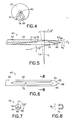
Figure 4 is a distal end view of the fracture fixation system of the invention; -
Figure 5 is an enlarged section view of the distal end of the drill according to the first embodiment of the fracture fixation system of the invention; -
Figure 6 is an enlarged bottom view of the drill of the distal end of the drill according to the first embodiment of the fracture fixation system of the invention; -
Figure 7 is an enlarged distal end view of the drill of the according to the first embodiment of the fracture fixation system of the invention; -
Figure 8 is a cross-section through line 8-8 inFigure 7 ; -
Figures 9, 10, and 11 are cross-section views through lines 9-9, 10-10, and 11-11, respectively, inFigure 2 ; -
Figure 12 is a side view of the fixation pin of the fracture fixation system of the invention; -
Figure 13 is an enlarged perspective view of the distal end of the shaft and the fixation pin; -
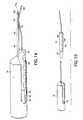
Figure 14 is a perspective view of the system of the first embodiment of the invention with the pin handle and fixation pin shown in a partial distal configuration relative to the main handle and drill; -
Figure 15 is a perspective view of the system of the first embodiment of the invention with the pin handle and fixation pin shown separated from the main handle and drill; -
Figure 16 is a perspective view of a second embodiment of the fracture fixation system according to the invention; -
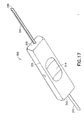
Figure 17 is a perspective view of a supplemental re-guiding tool for use in the fracture fixation according to the invention; -
Figure 18 is a side elevation of a second embodiment of the instrument of the fracture fixation system of the invention shown with an inner awl component extending through the shaft; -
Figure 19 is a side elevation of the second embodiment of the instrument shown a fixation pin extending through the shaft in place of the inner awl component; -
Figure 20 is a side elevation of a third embodiment of the instrument of the fracture fixation system of the invention; -
Figure 21 is a side elevation of a fourth embodiment of the instrument of the fracture fixation system of the invention; -
Figure 22 is an alternative embodiment of the fixation pin of the of the fracture fixation system of the invention; -
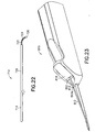
Figure 23 is a perspective view of a fifth embodiment of fracture fixation system; -
Figure 24 is side elevation of a set of fixation pins according to a sixth embodiment of the invention; -
Figure 25 is a section view of a torsionally stabilized fixation system according to the sixth embodiment of the invention; -
Figure 26 is a top view of a collet according to the sixth embodiment of the invention; -
Figure 27 is a section view of a torsionally stabilized fixation system according to a seventh embodiment of the invention; -
Figure 28 is a top view of a first collet according to the seventh embodiment of the invention; and -
Figure 29 is a top view of a second collet according to the seventh embodiment of the invention. - As stated above, the invention will be described with reference to a fracture in a metacarpal bone, although it also applies to fixating fractures in metatarsal and phalangeal bones. Turning now to
Figures 1 through 4 , a metacarpalfracture fixation system 10 for the insertion of a fixation pin into the medullary canal of a fractured metacarpal bone is shown. Thesystem 10 includes afixation pin 12 and aninstrument 14 for implanting the fixation pin. According to a first embodiment of the invention, theinstrument 14 includes amain handle 16 provided with astationary drill 40, and apin handle 18 movable relative to the main handle for implanting thefixation pin 12. - The
main handle 16 includes aproximal end 20, a preferably frustoconicaldistal end 22, a longitudinal drill slot 24 (seen best inFigs. 1 and9 ) preferably in alignment with a longitudinal axis AH of themain handle 16, tworadial bores 26, 28 which extend into thedrill slot 24, and apin handle slot 30 and pin handle bore 32 (seen best inFigs. 11 and15 ), both for receiving thepin handle 18, as described below. Themain handle 16 is preferably chamfered about thepin handle slot 30, and also preferably includes a plurality ofindentations 34 to facilitate engagement of themain handle 16 by the fingers of one hand (or both hands) of the physician. The main handle is preferably molded from plastic, e.g., ABS, nylon, polycarbonate, or polyethylene, but may be machined from a Delrin™ rod or a similar material. - The
drill 40 is provided in thelongitudinal drill slot 24. Thedrill 40 includes ashaft 42 having aproximal end 44 provided with twolateral bores 46, 48 (Fig. 2 ), and adistal end 50 described in detail below. Thedrill 40 is fixed in themain handle 16 with two pins 54, 56 secured, preferably by interference fit, through the lateral bores 26, 28 in themain handle 16 and into the lateral bores 46, 48 in theshaft 42 of thedrill 40. Thedrill 40 is preferably made from a stainless steel bar having a 0.125 inch (1 inch = 25,4 mm) diameter and a length of approximately 5.7 inches. Approximately 1.7 inches of the shaft is provided in the handle and approximately 4 inches of the shaft extend distally from themain handle 16. - Referring to
Figs. 5 through 8 , thedistal end 50 of theshaft 42 of thedrill 40 includes aboring tip 60 which preferably comprises threecutting edges point 68. The taper is preferably at approximately 13° relative to the longitudinal axis AS. In addition, and according to a preferred aspect of the invention, thedistal end 52 is provided with alateral guiding groove 70 which guides thefixation pin 12. The guidinggroove 70 includes a proximal slopedportion 72 and a distalcurved deflecting portion 74. The sloped portion is preferably sloped such that a line LP perpendicular to a surface 76 of the slopedportion 70 is angled approximately 5° to 8° relative to a line LS perpendicular to the axis AS of theshaft 42. Thecurved portion 74 preferably has a radius of approximately 0.50 inches. In a preferred embodiment, the guidinggroove 70 preferably extends into the shaft 42 a groove depth DG of approximately 0.110 inches at the intersection of the slopedportion 72 and thecurved portion 74, and preferably has a width WG of approximately 0.063 inches. The groove depth DG is preferably greater than the diameter of thepin 12 such that the combined diameters of thepin 12 and theshaft 42 at the guidinggroove 70 does not exceed the outer diameter of the shaft (Fig. 13 ). The width WG is preferably 0.002-0.003 inch greater than the diameter of the pin so that the pin is accurately guided without binding. - Referring to
Figs. 1-4 ,9-11 , and14-15 , the pin handle 18 includes adistal portion 80 which is sized and shaped to slidably move within thepin handle slot 30 of themain handle 16, and aproximal portion 82 which is sized and shaped to slidably move within the pin handle bore 32 of themain handle 16. Alower area 84 of thedistal portion 80 includes a plurality ofindentations 86 which facilitates movement of the pin handle 18 relative to themain handle 16 by fingers of the physician. Adistal end 88 of the pin handle 18 is chamfered and provided with abore 90 into which thefixation pin 12 is secured, preferably by an interference fit. The pin handle 18, like themain handle 16, is also preferably molded from plastic, e.g., ABS, nylon, polycarbonate, or polyethylene, but may be machined from a Delrin™ rod or a similar material. - As shown in
Figures 2 and12 , thefixation pin 12 preferably includes a substantially straightproximal portion 92, the end of which is secured in thedistal end 88 of thepin handle 18, a substantially straightcentral portion 94, which may optionally be angled relative to theproximal portion 92, and a curved,distal portion 96 having a preferablyblunt tip 98. If theproximal portion 92 andcentral portion 94 are angled relative to each other, it is preferable that the angle be approximately 5°-8°. Thedistal tip 96 is preferably curved about an approximately 0.50inch 1 inch = 25,4 mm radius for approximately 33° degrees. Thefixation pin 12 is preferably made from a solid metal wire material, e.g., stainless steel. It will be appreciated that the fixation pin must have a stiffness sufficient to immobilize the bone fracture, yet be resiliently flexible enough to permit thepin 12 to be sufficiently bent for insertion into the medullary canal of the bone, as described below. Therefore, thesystem 10 may include a plurality of fixation pins 12 having various diameters. Onepreferred fixation pin 12 preferably has a length of approximately 6.0 inches, with approximately 0.70 inches secured in thedistal bore 90 of thepin handle 18, and a diameter of approximately 0.060 inches. - Referring now to
Figs. 1 ,13 , and14 , thefixation pin 12 is positioned in thepin handle 18, and the pin handle 18 in themain handle 16 such that the curveddistal portion 96 of thefixation pin 12 rests within the guidinggroove 70 of theshaft 42 of thedrill 40, and thedistal portion 96 does not extend beyond the circumferential profile of the shaft. Referring toFig. 14 , movement of the pin handle 18 within thepin handle slot 30 and pin handle bore 32 of themain handle 16 distally relative to the main handle causes thedistal portion 96 of thefixation pin 12 to move relative to theshaft 42 of thedrill 40, through the guidinggroove 70, and to extend beyond theboring tip 60, at an angle relative to the axis of the shaft AS. The pin handle may be moved to extend the distal end of the pin preferably at least one quarter inch, and more preferably one to three inches, beyond the distal end of the shaft while remaining coupled to the main handle. Moreover, it will be appreciated that no impediment is present which inhibits the pin handle 18 from being moved distally relative to themain handle 16, or the main handle moved proximally relative to the pin handle. As such, as shown inFig. 15 , the pin handle may be separated from the main handle. - In use, the
main handle 16 of theinstrument 14 is manipulated by hand to subcutaneously introduce theboring tip 60 of thedrill 40 into the base of a fractured metacarpal bone. Once theboring tip 60 of thedrill 40 has entered the base of the metacarpal bone, the drill is oriented such that the guidinggroove 70 is oriented to guide thefixation pin 12 through the natural hollow of the medullary canal of the metacarpal bone. The pin handle 18 is then manually moved relative to themain handle 16 to force the curveddistal portion 96 of thefixation pin 12 into the bone. Themain handle 16 is then moved proximally relative to the pin handle 18 to remove thedrill 40 from the bone and disengage the main handle from the pin handle. This is performed while preferably maintaining the pin handle, and the fixation pin which is attached thereto, at its present location. The pin handle is then manipulated to move the pin through the canal of the fractured metacarpal bone until the pin extends on either side of the fracture and provides the necessary immobilization of the fractured bone. It will be appreciated that the complementary shape of the fixation pin and groove (e.g., the 5°-8° angle of the central portion of the pin relative to the proximal portion of the pin is substantially similar to the 5°-8° angle of the proximal portion of the groove, and the 0.50inch 1 inch = 25,4 mm radius of curvature of the distal portion of the pin is substantially the same as the 0.50 inch radius of curvature of the distal portion of the groove), facilitates directing the fixation pin into the medullary canal. Theblunt tip 98 of thefixation pin 12 prevents the pin from piercing the distal end of the metacarpal bone. Finally, once the physician determines that the fixation pin is properly fixating the fractured bone, the pin handle 18 may then be manipulated to bend thefixation pin 12 adjacent the cutaneous entrance hole, the pin is cut, and the cut end is either subcutaneously seated or covered with a bandage outside the skin. After fracture healing, the fixation pin is extracted, e.g., with pliers, from the bone and then discarded. The cutaneous entrance hole is then permitted to heal. - It will be appreciated that the fracture fixation system of the invention provides substantial fixation to a metacarpal fracture, yet does not require an unduly invasive procedure or a large number of steps. In addition, the procedure reduces the number of physician "hands", relative to invasive surgery, required to sufficiently immobilize a fracture for proper healing.
- Turning now to
Fig. 16 , a second embodiment of aninstrument 214 for afracture fixation system 210, substantially similar to the first embodiment (with like parts having numbers incremented by 200) is shown. Theinstrument 214 includes ashaft 240 having adistal guiding groove 270 and sharpboring end 260. Theshaft 240 includes ashaft handle 216 for manipulating the shaft. The shaft handle 216 includes aslot 230 into which apin handle 218 is slidably received. Theslot 230 preferably slopes downward toward the shaft. The shaft handle 216 is further provided withgrips 217 for stably gripping theshaft handle 216 in a hand of the physician. The pin handle 218 includes aridge 219 which may be used to leverage relative distal movement of the pin handle through theslot 230 of theshaft handle 216. The pin handle 218 and the shaft handle 216 are preferably positively engagable relative to each other, e.g., with a snap fit, and may be disengaged by sufficient force on theridge 219 of the pin handle to move the pin handle relative to the shaft handle. Release may also provide tactile indication that the handles have disengaged and atip 298 of thepin 212 has moved slightly ahead of theboring tip 260 of theshaft 240. The slope of theslot 230 permits afixation pin 212 provided axial within the pin handle to be directed toward and through the guidinggroove 270 when the pin handle is located in theslot 230 and moved within the slot. Thepin 212 is preferably angled relative to a longitudinal axis AP of the shaft handle 216 such that thepin 212 is directed toward theshaft 240. Preferably, thefixation pin 212 includes aproximal portion 292 and acentral portion 294 which are coaxially aligned, and adistal portion 296 provided with the blunt, preferably curvedtip 298. In operation, after theboring end 260 of theshaft 240 has been inserted into the metacarpal bone, thepin handle 218 is moved distally relative to the shaft handle to move thepin 212 through the guidinggroove 270 and into the medullary canal of the fractured bone. The shaft handle 216 is then removed from thepin handle 218, and the pin handle is manipulated to further extend the fixation pin through the medullary canal of the bone and fixate the bone. After the physician is assured that the fixation pin provides desirable fixation of the fracture (i.e., that it has sufficient diametric fit within the medullary canal), the pin is bent and cut at the skin surface. - It will be appreciated that after inserting a fixation pin into the medullary canal (but prior to bending and cutting the pin), in certain circumstances, the physician may determine that the inserted pin is unsuitably sized for the particular patient, and that a fixation pin having a different diameter is required. To that end, a set of fixation pins including fixation pins having distal portions of various sizes (e.g., substantially 0.060, substantially 0.051 inch, 1 inch = 25,4 mm substantially 0.045 inch, substantially 0.038 inch, and substantially 0.035 inch) is provided for use by the physician. However, if the pin presently inserted in the hand is removed from the hand for replacement, the entry hole in the bone will be difficult to relocate. Therefore, referring to
Fig. 17 , a supplementalre-guiding tool 300 may be provided in the system of the invention. There-guiding tool 300 includes ahandle 302, a slottedshaft 304 extending from oneend 306 of the handle and having an inclined leadingedge 308, and atubular bending portion 310 extending from theother end 312 of the handle. Thehandle 302 is preferably further provided with adepression 314 into which the thumb of the physician may seat and which thereby facilitates gripping the handle. - The slotted
shaft 304 of there-guiding tool 300 may be extended over the fixation pin which the physician wants to replace, through the entry hole in the hand, and into the hole in the bone. The inclinedleading edge 308 facilitates insertion of the shaft through the wound of the hand with minimal trauma to the area. It will be appreciated that the slotted shaft design provides a less traumatic manner of maintaining a pathway from the entry hole in the skin to the bone than reinserting the distal end of the boring shaft (drill). The fixation pin may then be removed, while the slottedshaft 304 acts as a guide for the replacement pin. Once the proper fixation pin has finally been determined, the pin is cut and there-guiding tool 300 may be reversed and the bendingportion 310 may be extended over the cut pin and used to leverage the bending of the pin for subsequent subcutaneous seating. While theguide tool 300 is most appropriately used with the first and second embodiments of the invention (which are provided with lateral pin guides), it will be appreciated that the guide tool may also be used with any of the following embodiments. - Turning now to
Fig. 18 , a third embodiment of aninstrument 414 for afracture fixation system 410 according to the invention is shown. Theinstrument 414 includes ashaft handle 416 having anaxial throughbore 424 and aboring shaft 440 coupled in the distal end thereof. Theshaft 440 is cannulated; i.e., theshaft 440 is provided with aninternal pathway 470, and preferably includes adistal tip 460 with anaxial pathway exit 471 and a preferably sharpannular cutting edge 473. Theaxial throughbore 424 andinternal pathway 470 are in communication with each other and preferably axially aligned. A rod-like awl 419, provided with aproximal handle 421, is extendable through and removable from thepathway 470. Theawl 419 preferably has a length such that when thehandle 421 of the awl is seated flushly against theshaft handle 416, thetip 423 of the awl extends through thepathway exit 471 and operates as a boring tip. The inner awl and shaft may be locked together for insertion into the bone. The awl is then unlocked and removed from theinternal pathway 470 to permit afixation pin 412 to be fed through thepathway 470 and out the pathway exit 471 (Fig. 19 ). - In use, the
awl handle 421 and shaft handle 416 is used to insert thetip 423 of theawl 419 and thetip 460 of theshaft 440 into the metacarpal bone. The awl handle 421 is then removed from thepathway 470, and thefixation pin 412 is maneuvered through the pathway and into the medullary canal. Once the fixation pin is sufficiently extended in the medullary canal to fixate the bone on either side of the fracture, themain handle 416 is proximally removed from over thepin 412. The pin may then be further manipulated, and is finally cut at the desired length. - Referring now to
Fig. 20 , a fourth embodiment of aninstrument 514 for afracture fixation system 510 is shown. Theinstrument 514 includes amain handle 516 having athroughbore 524 and aboring shaft 540 coupled in the distal end thereof. Theboring shaft 540 is cannulated and, at itsdistal end 550 includes a sharp boringdistal tip 560 and alateral pathway exit 571. A rod (not shown, but similar to the awl described with respect to the second embodiment) may be provided within thepathway 570 such that it closes thepathway exit 571 and thereby facilitates insertion of theshaft 540 into the bone. The rod, if provided, is then removed. Afixation pin 512 is then extended through thepathway 570 and into the medullary canal of the metacarpal bones. - Turning now to
Fig. 21 , a fifth embodiment of aninstrument 314 for afracture fixation system 610 is shown. Theinstrument 614 includes a cannulatedboring shaft 640 preferably provided with aproximal shaft handle 616, and afixation pin 612 optionally having apin handle 618 coupled to its proximal end. The cannulatedshaft 640 includes a proximallateral pin entry 669 into anaxial pathway 670 of theshaft 640, and a distallateral pathway exit 671 oriented to guide the pin into the medullary canal. Optionally, thepathway exit 671 may be axially aligned with thepathway 670 for axial guidance of the pin. After theshaft 640 has been inserted into the metacarpal bone, thepin 612 manipulated through theshaft 640 and into the canal of the fractured bone to fixate the bone. Where no pin handle is provided, theshaft 640 and shaft handle 616 are then proximally withdrawn over thepin 612, and the pin is manipulated such that it is sufficiently inserted, bent, and finally cut to the desired length. Where the optional pin handle 618 is utilized, theshaft 640 is moved proximally over thepin 612 toward the pin handle 618 such that the pin may be further manipulated and cut to the desired length. - Turning now to
Fig. 22 , the fixation pin used in each of the above embodiments may be alternatively configured. For example, thefixation pin 712 may be provided with a narrowed portion 722 (i.e., a reduced diameter) adjacent thetip 720 about which acoil 724 is preferably positioned. This configuration is provided to permit the distal end 718 of the fixation pin to more easily bend and permit the fixation pin to preferably be self-guiding to follow the medullary canal. In addition, as an alternative to stainless steel, thepin 712 may be made from titanium, or another structurally supportive biocompatible material. - Referring now to
Fig. 23 , the pin handle 818 of thefixation system 810 may be provided with a set of fixation pins, substantially as described above with respect to the first embodiment but having a variety of distal dimensions. For example, it may be desirable to insert apin 812 into a phalangeal medullary canal having a relatively smaller distal diameter than would be desirable for a metacarpal bone. However, in order to permit the pin handle 818 to easily accommodate and stably hold pins having a variety of distal dimensions, the dimensions of theproximal portion 892 of the pins may be provided with a preferably uniform dimension. As such, some fixation pins 812 may have a distally tapered portion 813 (or alternatively astep 813a, shown in dotted line), along theproximal portion 892 of the pin to taper to their respective distal dimension. - Turning now to
Fig. 24 , a fixation system may be provided with a plurality, or set 900, offixation pins Fig. 25 , the pins are individually inserted into the medullary canal of the fractured bone substantially as described above; i.e., using an instrument including a shaft having a guiding groove and provided with a shaft handle for manipulating the shaft, and a pin handle coupled to the proximal end of the pin. Afirst pin 912a is provided in the pin handle and inserted into themedullary canal 913 of abone 915 to extend across afracture 911 in the bone, as described above. Asecond pin 912b is inserted alongside thefirst pin 912a, and optionally additional pins, e.g., 912c, are likewise inserted. The distal ends of the pins may diverge to rest or imbed in different portions of the bone, as shown or, alternatively, may remain substantially aligned. Referring toFigs. 25 and 26 , acylindrical collet 917 is then positioned over the exposed proximal ends of the pins to constrain the pins together such that the pins are substantially prevented from relative axial rotation. Thecollet 917 preferably includes acentral opening 919 adapted to stably secure the pins. For example, for three pins, thecentral opening 919 may be circular with a diameter adapted to hold the three pins together. In addition, thecollet 917 also preferably includes a means for securing the collet, and therefore the proximal ends of the fixation pins, to the fractured bone, e.g., external and preferably self-tappingthreads 921. Anexternal flange 923 adapted to assist in seating the collet at the desired depth in the bone is also preferably provided. As such, the fixation system provides torsional stabilization to the fracture. - Turning now to
Figs. 27 and 28 , in another torsionally stabilized fracture fixation system, twopins bone 1015 to bridge thefracture 1011 as described above. Acollet 1017 having threeopenings Fig. 29 ) is provided over the proximal ends of the pins with the pins extending through two of theopenings opening 1019c, anail 1121 is provided and secured into the bone to immobilize thecollet 1017 relative to the bone. - There have been described and illustrated herein several embodiments of a fracture fixation system. While particular embodiments of the invention have been described, it is not intended that the invention be limited thereto, as it is intended that the invention be as broad in scope as the art will allow and that the specification be read likewise. Thus, while some embodiments of the fixation system have been particularly disclosed for the fixation of fractured metacarpal bones, it will be appreciated that the system may be used to fixate bones of similar or smaller size and for which similar problems exist with respect to fracture fixation, e.g., metatarsal bones in the foot and the phalanges of the fingers and toes. In addition, pediatric arm bones, e.g., ulna and radial bones, can be similarly treated. Therefore, the teaching here is for the use of the system of the invention with the like bones. In addition, while particular materials have been disclosed with respect to the various components of the system of the invention, it will be appreciated that other suitable materials may be used as well. For example, while a metal fixation pin has been described, less preferred alternative materials for the fixation pin are nonmetals, in particular, bioabsorbable materials. Furthermore, while particular dimensions and angles have been disclosed and provide superior results, it will be understood that the components may be sized to other suitable dimensions and angles, as long as they are adapted to be used in a system to immobilize metacarpal bones and the like. For example, while the distal portion of the fixation pin and the distal surface of the groove are both preferable angled at between 5°-8°, it will be appreciated that other suitable angles, e.g., between 3° and 15°, may also be used. Also, while indentations are disclosed as finger gripping means, other finger gripping means, e.g., knurls, ridges, grooves, and nubs, may additionally or alternatively be used. In addition, while the bone boring shaft component is described as a drill in the first embodiment, it will be appreciated that the shaft component is not required to have any cutting edges, and may be provided with a sharp point to enter the bone. Furthermore, while machined handles are disclosed for moving the fixation pin relative to the shaft component, it will be appreciated that pliers or the like may similarly be used to hold and move the pin through the guiding means of the shaft. Further yet, while pins have been described for holding the drill shaft in the main handle, it will be appreciated that other means for fixing the drill in the handle. In addition, while a cylindrical collet has been shown holding the proximal ends of pins together, it will be appreciated that devices having different shapes and configurations can likewise be used to constrain the pin ends together. For example, sleeves, bands, clips, staples, etc., may be used. Also, while in one embodiment a nail is shown extending through the collet, it will be appreciated that a screw or similar fastener can likewise be used. It will therefore be appreciated by those skilled in the art that yet other modifications could be made to the provided invention without deviating from its scope as so claimed.
Claims (22)
- A fracture fixation system (10) for stabilizing a fracture of a human bone, said system comprising:a fixation pin (12) having a proximal end and a distal end, said fixation pin (12) being sized to snugly fit within the medullary canal of the bone and having a stiffness sufficient to immobilize the fracture and a flexibility sufficient to permit the fixation pin (12) to bend to facilitate insertion into the medullary canal; andan elongate shaft (42) having a proximal end, a distal end with means for boring a hole (60) in the bone in a first direction axial with said shaft (42), and a pin guide groove (70) adjacent said distal end of said shaft (42) for guiding said fixation pin (12) into the medullary canal of the bone at an oblique angle relative to said first direction,said fixation pin (12) and said shaft (42) both adapted such that said distal end of said fixation pin (12) is movable beyond said distal end of said shaft (42), and wherein said distal end of said pin (12) contacts said pin guide groove (70) on said shaft (42) as said fixation pin (12) is slidably moved beyond said distal end of said shaft.
- A fracture fixation system (10) according to claim 1, further comprising:a first handle (18) coupled to said proximal end of said fixation pin (12) which facilitates movement of said fixation pin (12) relative to said shaft (42) and through said pin guide groove (70), said first handle (18) preferably including a finger engageable structure which facilitates movement of said fixation pin (12) into the medullary canal.
- A fracture fixation system (10) according to claim 2, further comprising:a second handle (16) coupled to said proximal end of said shaft (42) to facilitate movement of said shaft (42) into the bone, said second handle (16) preferably provided with a longitudinal opening (30) into which said first handle (18) is received and distally slidable therein.
- A fracture fixation system (10) according to claim 3, wherein:said first handle (18) is either removable from said longitudinal opening (30) or releasably engageable within said longitudinal opening (30).
- A fracture fixation system (10) according to any preceding claim, wherein:said pin guide groove (70) includes a proximal sloped surface (72) and a distal curved surface (74).
- A fracture fixation system (10) according to any preceding claim, wherein:said means for boring (60) includes a plurality of cutting edges (62, 64, 66) which meet at a point (68).
- A fracture fixation system (10) according to claim 3, wherein:at least one of said first handle (18) and said second handle (16) is provided with means for gripping with a hand of a person.
- A fracture fixation system (10) according to any preceding claim, further comprising:a guide tool (300) having a shaft (304) provided with a slot, said slot having a lateral opening sized to fit over said fixation pin (12).
- A fracture fixation system (10) according to any preceding claim, wherein:said fixation pin (12) comprises an elongate rod having a proximal portion (92), a central portion (94), and a curved distal portion (96).
- A fracture fixation system (10) according to claim 9, wherein:said proximal portion (92) is straight and said central portion (94) is straight and/or said central portion (94) is angled at an angle relative to said proximal portion (92) where said angle is preferably approximately 5° to 8° and said curved distal portion (96) preferably has a radius of curvature of approximately 12.7 mm.
- A fracture fixation system (10) according to any preceding claim, wherein;
said fixation pin (712) is provided with a reduced diameter portion (722) adjacent said distal end of said fixation pin (712), and a coil (724) is preferably provided about said reduced diameter portion (727). - A fracture fixation system (10) according to claims 1 through 5, wherein;
said pin guide groove (70) is adapted to deflect said distal end of said fixation pin (12) at an angle relative to a longitudinal axis of said shaft (42) when said fixation pin (12) is moved distally relative to said shaft (42). - A fracture fixation system (10) according to claims 1 through 5, wherein;
said fixation pin (12) has a distal portion (96) terminating in said distal end, said distal portion (96) having a non-linear shape, and
said pin guide groove (70) defines a non-linear shape (74) substantially similar to said non-linear shape of said distal portion (96) of said fixation pin (12), such that when said boring tip (60) of said shaft (42) is entered into the bone and said fixation pin (12) is moved distally relative to said shaft (42), said pin guide groove (70) guides said fixation pin (12) into said medullary canal of the bone at an angle relative to a longitudinal axis of said shaft (42). - A fracture fixation system (10) according to claim 13, wherein:said non-linear shape of said distal portion (96) of said fixation pin (12) includes a proximal straight first portion and a curved distal second portion.
- A fracture fixation system (10) according to claim 14, wherein:said pin guide groove (70) includes a surface (72) having a first portion which is angled a approximately 5° - 8° relative to said longitudinal axis and a second portion (74) which has a radius of curvature of approximately 12.7 mm.
- A fracture fixation system (10) according to any preceding claim, wherein:said fixation pin (12) is sized to fit into the medullary canal of one of a human metacarpal bone, human metatarsal bone, human phalangeal bone, pediatric ulna bone, and pediatric radial bone.
- A fracture fixation system (10) according to claims 1 through 15, further comprising:at least one additional fixation pin (912, 1012), having a proximal end and a distal end, said fixation pins (912, 1012) each being sized to fit together within the medullary canal of the bone and having a combined stiffness sufficient to immobilize the fracture and an individual flexibility sufficient to permit each of said plurality of fixation pins (912, 1012) to bend to facilitate insertion into the medullary canal.
- A fracture fixation system (10) according to claim 17, further comprising:a means (917, 1017) for securing said proximal ends of said fixation pins (912, 1012) together.
- A fracture fixation system (10) according to claim 18, wherein:said means (917, 1017) for securing additionally secures said fixation pins (912, 1012) to the bone.
- A fracture fixation system (10) according to claim 19, wherein;
said means (917, 1017) for securing includes a collet (1017) and a fastener (1121), said collet (1017) surrounding said proximal ends of said fixation pins (1012), and said fastener (1121) extending through said collet (1017) and into the bone, said collet (1017) preferably provided with self-tapping threads. - A fracture fixation system (10) according to claims 17 through 20, wherein:said fixation pins (912, 1012) are sized to fit together within the medullary canal of one of a human metacarpal bone, human metatarsal bone, human phalangeal bone, pediatric ulna bone, and pediatric radial bone.
- A fracture fixation system (10) according to claims 17 through 21, wherein;
each of said plurality of fixation pins (912, 1012) is provided with a distal diameter between approximately 0.889 mm and 1.524 mm.
Priority Applications (1)
| Application Number | Priority Date | Filing Date | Title |
|---|---|---|---|
| EP10182519A EP2292166B1 (en) | 1998-09-10 | 1999-09-02 | Fracture fixation system |
Applications Claiming Priority (3)
| Application Number | Priority Date | Filing Date | Title |
|---|---|---|---|
| US09/150,792 US6200321B1 (en) | 1998-09-10 | 1998-09-10 | Fracture fixation system |
| PCT/US1999/020214 WO2000015123A1 (en) | 1998-09-10 | 1999-09-02 | Fracture fixation system |
| US150792 | 2002-05-17 |
Related Child Applications (1)
| Application Number | Title | Priority Date | Filing Date |
|---|---|---|---|
| EP10182519.8 Division-Into | 2010-09-29 |
Publications (3)
| Publication Number | Publication Date |
|---|---|
| EP1119302A1 EP1119302A1 (en) | 2001-08-01 |
| EP1119302A4 EP1119302A4 (en) | 2003-02-05 |
| EP1119302B1 true EP1119302B1 (en) | 2011-03-16 |
Family
ID=22536019
Family Applications (2)
| Application Number | Title | Priority Date | Filing Date |
|---|---|---|---|
| EP99945466A Expired - Lifetime EP1119302B1 (en) | 1998-09-10 | 1999-09-02 | Fracture fixation system |
| EP10182519A Expired - Lifetime EP2292166B1 (en) | 1998-09-10 | 1999-09-02 | Fracture fixation system |
Family Applications After (1)
| Application Number | Title | Priority Date | Filing Date |
|---|---|---|---|
| EP10182519A Expired - Lifetime EP2292166B1 (en) | 1998-09-10 | 1999-09-02 | Fracture fixation system |
Country Status (9)
| Country | Link |
|---|---|
| US (2) | US6200321B1 (en) |
| EP (2) | EP1119302B1 (en) |
| JP (1) | JP4159748B2 (en) |
| AT (2) | ATE501676T1 (en) |
| AU (1) | AU744954B2 (en) |
| BR (1) | BR9913631A (en) |
| CA (1) | CA2343378C (en) |
| DE (1) | DE69943285D1 (en) |
| WO (1) | WO2000015123A1 (en) |
Families Citing this family (59)
| Publication number | Priority date | Publication date | Assignee | Title |
|---|---|---|---|---|
| SE517570C2 (en) * | 2000-08-09 | 2002-06-18 | Lars Johan Henrik Hansson | Device for fixing means for fixing bone fragments in case of fracture |
| US6527775B1 (en) * | 2000-09-22 | 2003-03-04 | Piper Medical, Inc. | Intramedullary interlocking fixation device for the distal radius |
| US7169165B2 (en) * | 2001-01-16 | 2007-01-30 | Boston Scientific Scimed, Inc. | Rapid exchange sheath for deployment of medical devices and methods of use |
| US20050049594A1 (en) * | 2001-04-20 | 2005-03-03 | Wack Michael A. | Dual locking plate and associated method |
| US20020156474A1 (en) * | 2001-04-20 | 2002-10-24 | Michael Wack | Polyaxial locking plate |
| US6533788B1 (en) | 2001-11-01 | 2003-03-18 | Hand Innovations, Inc. | Locking device for intramedullary pin fixation |
| US6660009B1 (en) | 2002-05-15 | 2003-12-09 | Carlos A. Azar | Fracture fixation system |
| US7001389B1 (en) | 2002-07-05 | 2006-02-21 | Navarro Richard R | Fixed and variable locking fixation assembly |
| CA2495110C (en) | 2002-08-10 | 2008-11-18 | H. Simon William | Method and apparatus for repairing the mid-foot region via an intramedullary nail |
| US7204839B2 (en) * | 2002-09-04 | 2007-04-17 | Arthrex, Inc. | Method of using offset drill guide in arthroscopic surgery |
| FR2844992B1 (en) * | 2002-09-30 | 2006-09-29 | Fixano | OSTEOSYNTHESIS PIN FOR SMALL BONES, METHOD OF MANUFACTURING THE PIN AND INSTRUMENT FOR SETTING SAID PIN INTO A BONE |
| US20040111090A1 (en) * | 2002-10-03 | 2004-06-10 | The University Of North Carolina At Chapel Hill | Modification of percutaneous intrafocal plate system |
| US7278997B1 (en) | 2003-03-07 | 2007-10-09 | Theken Spine, Llc | Instrument guide and implant holder |
| US20040243135A1 (en) * | 2003-05-28 | 2004-12-02 | Tomoaki Koseki | Hand drill |
| BRPI0413472A (en) * | 2003-08-13 | 2006-10-17 | Synthes Gmbh | curved positioning and introducing instrument for inserting a guidewire into the femur, process of positioning an opening guidewire into an intramedullary canal of a femur with an instrument, and instrument cluster |
| US7632284B2 (en) | 2004-07-06 | 2009-12-15 | Tyco Healthcare Group Lp | Instrument kit and method for performing meniscal repair |
| US20060015101A1 (en) * | 2004-07-15 | 2006-01-19 | Wright Medical Technology, Inc. | Intramedullary fixation assembly and devices and methods for installing the same |
| US7588577B2 (en) * | 2004-07-15 | 2009-09-15 | Wright Medical Technology, Inc. | Guide assembly for intramedullary fixation and method of using the same |
| US20060184186A1 (en) * | 2005-02-16 | 2006-08-17 | Medtronic Vascular, Inc. | Drilling guidewire for treating chronic total occlusion |
| US9060820B2 (en) | 2005-05-18 | 2015-06-23 | Sonoma Orthopedic Products, Inc. | Segmented intramedullary fracture fixation devices and methods |
| US7846162B2 (en) | 2005-05-18 | 2010-12-07 | Sonoma Orthopedic Products, Inc. | Minimally invasive actuable bone fixation devices |
| US8961516B2 (en) | 2005-05-18 | 2015-02-24 | Sonoma Orthopedic Products, Inc. | Straight intramedullary fracture fixation devices and methods |
| US7704257B2 (en) * | 2005-11-23 | 2010-04-27 | Stryker Trauma S.A. | Compression instrument |
| AU2007323570A1 (en) * | 2006-11-22 | 2008-05-29 | Sonoma Orthopedic Products Inc. | Surgical tools for use in deploying bone repair devices |
| CA2670263A1 (en) | 2006-11-22 | 2008-05-29 | Sonoma Orthopedic Products, Inc. | Fracture fixation device, tools and methods |
| US8771283B2 (en) | 2007-12-17 | 2014-07-08 | Wright Medical Technology, Inc. | Guide assembly for intramedullary fixation and method of using the same |
| FR2927792A1 (en) * | 2008-02-25 | 2009-08-28 | Dominique Persoons | S-shaped percutaneous radial nail for treating fracture of radial bone of aged person, has ends with different elasticities, and proximal and distal locking devices, where nail is made of elastic metal alloy and has non-constant diameter |
| US8915916B2 (en) | 2008-05-05 | 2014-12-23 | Mayo Foundation For Medical Education And Research | Intramedullary fixation device for small bone fractures |
| EP2299917A1 (en) | 2008-06-10 | 2011-03-30 | Sonoma Orthopedic Products, Inc. | Fracture fixation device, tools and methods |
| AU2009296243A1 (en) | 2008-09-26 | 2010-04-01 | Sonoma Orthopedic Products, Inc. | Bone fixation device, tools and methods |
| US8540714B2 (en) | 2010-05-11 | 2013-09-24 | Orthopediatrics Corp. | Pediatric intramedullary nail |
| US9072564B2 (en) | 2010-06-02 | 2015-07-07 | Wright Medical Technology, Inc. | Hammer toe implant and method |
| US9724140B2 (en) | 2010-06-02 | 2017-08-08 | Wright Medical Technology, Inc. | Tapered, cylindrical cruciform hammer toe implant and method |
| US9498273B2 (en) | 2010-06-02 | 2016-11-22 | Wright Medical Technology, Inc. | Orthopedic implant kit |
| US8608785B2 (en) | 2010-06-02 | 2013-12-17 | Wright Medical Technology, Inc. | Hammer toe implant with expansion portion for retrograde approach |
| CA2847182C (en) | 2011-09-02 | 2020-02-11 | Stryker Corporation | Surgical instrument including a cutting accessory extending from a housing and actuators that establish the position of the cutting accessory relative to the housing |
| US9439768B2 (en) | 2011-12-08 | 2016-09-13 | Imds Llc | Glenoid vault fixation |
| US9414927B2 (en) | 2011-12-08 | 2016-08-16 | Imds Llc | Shoulder arthroplasty |
| US9414873B2 (en) | 2012-01-05 | 2016-08-16 | The Cleveland Clinic Foundation | Modular bone fixation system |
| US9788957B2 (en) | 2012-12-07 | 2017-10-17 | Cleveland Clinic Foundation | Glenoid vault fixation |
| US8945232B2 (en) | 2012-12-31 | 2015-02-03 | Wright Medical Technology, Inc. | Ball and socket implants for correction of hammer toes and claw toes |
| US9724139B2 (en) | 2013-10-01 | 2017-08-08 | Wright Medical Technology, Inc. | Hammer toe implant and method |
| US9474561B2 (en) | 2013-11-19 | 2016-10-25 | Wright Medical Technology, Inc. | Two-wire technique for installing hammertoe implant |
| US9770278B2 (en) | 2014-01-17 | 2017-09-26 | Arthrex, Inc. | Dual tip guide wire |
| US9498266B2 (en) | 2014-02-12 | 2016-11-22 | Wright Medical Technology, Inc. | Intramedullary implant, system, and method for inserting an implant into a bone |
| US9545274B2 (en) | 2014-02-12 | 2017-01-17 | Wright Medical Technology, Inc. | Intramedullary implant, system, and method for inserting an implant into a bone |
| FR3020261A1 (en) | 2014-04-28 | 2015-10-30 | Xavier Renard | SYSTEM FOR REUNNING AT LEAST TWO PORTIONS OF A LONG BONE |
| EP3188693B1 (en) | 2014-09-07 | 2020-05-27 | Ossio Ltd. | Anisotropic biocomposite material, medical implants comprising same and methods of treatment thereof |
| WO2016043751A1 (en) | 2014-09-18 | 2016-03-24 | Wright Medical Technology, Inc. | Hammertoe implant and instrument |
| US9814499B2 (en) | 2014-09-30 | 2017-11-14 | Arthrex, Inc. | Intramedullary fracture fixation devices and methods |
| CA2889595C (en) | 2014-12-19 | 2018-01-16 | Wright Medical Technology, Inc. | Intramedullary anchor for interphalangeal arthrodesis |
| CN107106210B (en) | 2014-12-26 | 2021-05-04 | 奥西奥有限公司 | Continuous Fiber Reinforced Biocomposite Medical Implants |
| CN106994040A (en) * | 2016-01-25 | 2017-08-01 | 刘彦宾 | A kind of orthopedic instrument |
| EP3426312B1 (en) | 2016-03-07 | 2026-03-25 | Ossio Ltd. | Surface treated biocomposite material, medical implants comprising same and methods of treatment thereof |
| KR102456201B1 (en) | 2016-06-27 | 2022-10-19 | 오씨오 리미티드 | Fiber-reinforced biocomposite medical implants with high mineral content |
| MX2020003481A (en) | 2017-10-11 | 2020-12-07 | Howmedica Osteonics Corp | Humeral fixation plate guides. |
| EP3998968B1 (en) | 2019-07-15 | 2025-08-06 | Stryker Corporation | Robotic hand-held surgical instrument systems |
| US12097346B1 (en) * | 2020-03-10 | 2024-09-24 | Ohiohealth Corporation | Thoracostomy device |
| IL294542B1 (en) | 2021-07-19 | 2026-02-01 | Ossio Ltd | Cannulated implant delivery device with adjustable insertion depth |
Family Cites Families (48)
| Publication number | Priority date | Publication date | Assignee | Title |
|---|---|---|---|---|
| US2631584A (en) * | 1948-07-22 | 1953-03-17 | Alfred T Purificato | Fracture securing instrument |
| DE1054659B (en) * | 1955-02-19 | 1959-04-09 | Dr Med Kurt Herzog | Tubular bone nail |
| US4055172A (en) | 1973-07-18 | 1977-10-25 | Josef Ender | Nail and set for correctly resetting fractured bones for their immediate re-use |
| US4169470A (en) * | 1977-10-19 | 1979-10-02 | Ender Hans G | Surgical nail for use in setting bone fractures, and tool for emplacing same |
| SE431053B (en) * | 1981-05-11 | 1984-01-16 | Lars Ingvar Hansson | RECOVERY INSTRUMENTS PROVIDED FOR THE RECOVERY OF A FIXING BODY FOR FIXING BONE FRAGMENT AT BONE BREAK |
| US4381770A (en) * | 1981-10-26 | 1983-05-03 | Neufeld Alonzo J | Method and apparatus for performing percutaneous bone surgery and new pin implant |
| US4491132A (en) * | 1982-08-06 | 1985-01-01 | Zimmer, Inc. | Sheath and retractable surgical tool combination |
| US4541423A (en) * | 1983-01-17 | 1985-09-17 | Barber Forest C | Drilling a curved hole |
| IL70736A (en) * | 1984-01-20 | 1988-05-31 | Rosenberg Lior | Self-locking pin device particularly useful for internally fixing bone fractures |
| RO89820B1 (en) * | 1985-11-05 | 2002-06-28 | îNTREPRINDEREA INDUSTRIA TEHNICO MEDICALA | Elastic implants for a stable elastic osteorrhaphy of femoral and tibial fractures, respectively, as well as corresponding instrumentation |
| US4793363A (en) * | 1986-09-11 | 1988-12-27 | Sherwood Medical Company | Biopsy needle |
| DE3924610A1 (en) * | 1988-07-28 | 1990-03-22 | Jawdat Dr Med Georges | Bone fracture distraction pin appts. - has long forked and short hooked pin clamped together at free ends |
| EP0427754B1 (en) | 1988-07-29 | 1995-02-08 | ROGER, Gregory James | Further improved method and apparatus for removing prosthetic cement |
| US5484442A (en) * | 1988-10-24 | 1996-01-16 | Cook Incorporated | Intraosseous needle |
| US5139500A (en) | 1989-05-08 | 1992-08-18 | Schwartz Nathan H | Bone attachment system |
| US5281225A (en) * | 1989-06-07 | 1994-01-25 | Guglielmo Vicenzi | Intramedullary pin with self-locking end for metadiaphyseal fractures of long bones |
| AT393617B (en) * | 1989-10-25 | 1991-11-25 | Ender Hans Georg | INSTRUMENTARIUM FOR REPOSITION AND FIXATION OF PER- AND SUBTROCHANTER FRACTURES |
| US5078719A (en) * | 1990-01-08 | 1992-01-07 | Schreiber Saul N | Osteotomy device and method therefor |
| US5057103A (en) * | 1990-05-01 | 1991-10-15 | Davis Emsley A | Compressive intramedullary nail |
| US5180388A (en) * | 1990-06-28 | 1993-01-19 | American Cyanamid Company | Bone pinning system |
| US5207753A (en) * | 1991-02-18 | 1993-05-04 | Kannivelu Badrinath | Bone fracture repair apparatus and method |
| US5257996A (en) * | 1991-12-13 | 1993-11-02 | Mcguire David A | Surgical pin passer |
| US5374270A (en) * | 1991-12-13 | 1994-12-20 | David A. McGuire | Device and method for insertion of guide pin |
| US5211647A (en) * | 1992-02-19 | 1993-05-18 | Arthrex Inc. | Interference screw and cannulated sheath for endosteal fixation of ligaments |
| DE4209122A1 (en) * | 1992-03-20 | 1993-09-23 | Kessler Sigurd | MARKING NAIL |
| US5425776A (en) * | 1992-05-07 | 1995-06-20 | Cohen; Michael | Method of using absorbable joint implants for the lesser digits and metatarsal phalangeal joints in the surgical correction of the foot |
| US5624446A (en) | 1992-09-11 | 1997-04-29 | University Of Washington | System for repair of capsulo-labral separations |
| US5409489A (en) * | 1993-01-12 | 1995-04-25 | Sioufi; Georges | Surgical instrument for cone-shaped sub-trochanteric rotational osteotomy |
| WO1995009569A1 (en) | 1993-10-04 | 1995-04-13 | Endocare Ag | Drill, and kirschner wires, bone drills, etc., fitted with such a drill |
| US5609595A (en) * | 1993-03-25 | 1997-03-11 | Pennig; Dietmar | Fixation pin for small-bone fragments |
| US5330468A (en) * | 1993-10-12 | 1994-07-19 | Burkhart Stephen S | Drill guide device for arthroscopic surgery |
| US5527316A (en) | 1994-02-23 | 1996-06-18 | Stone; Kevin T. | Surgical reamer |
| US5562673A (en) * | 1994-03-03 | 1996-10-08 | Howmedica Inc. | Awls for sizing bone canals |
| US5499984A (en) | 1994-04-07 | 1996-03-19 | Snap-On Incorporated | Universal modular reamer system |
| US5488761A (en) | 1994-07-28 | 1996-02-06 | Leone; Ronald P. | Flexible shaft and method for manufacturing same |
| DE4435497C1 (en) * | 1994-10-04 | 1996-07-04 | Amir Dr Zahedi | Modular bone implant with socket |
| US5578041A (en) * | 1994-10-14 | 1996-11-26 | Trustees Of The University Of Pennsylvania | External fixation device |
| US5571103A (en) * | 1994-10-18 | 1996-11-05 | Bailey; Kirk J. | Method for the fixation of bone |
| SE505452C2 (en) * | 1995-02-14 | 1997-09-01 | Robert J Medoff | An implantable fragment clip / support and method of making it |
| US5624447A (en) | 1995-03-20 | 1997-04-29 | Othy, Inc. | Surgical tool guide and entry hole positioner |
| US5591207A (en) | 1995-03-30 | 1997-01-07 | Linvatec Corporation | Driving system for inserting threaded suture anchors |
| US5681333A (en) | 1995-11-08 | 1997-10-28 | Arthrex, Inc. | Method and apparatus for arthroscopic rotator cuff repair utilizing bone tunnels for suture attachment |
| US5720749A (en) | 1996-03-18 | 1998-02-24 | Snap-On Technologies, Inc. | Integral reamer apparatus with guide counterbores in female press-fitted parts |
| US5851208A (en) | 1996-10-15 | 1998-12-22 | Linvatec Corporation | Rotatable surgical burr |
| US5893850A (en) * | 1996-11-12 | 1999-04-13 | Cachia; Victor V. | Bone fixation device |
| US5713868A (en) * | 1997-03-05 | 1998-02-03 | Fussman; Arie | Catheterization device with dilator |
| US5766179A (en) | 1997-03-05 | 1998-06-16 | Orthofix S.R.L. | Mechanical system for blind nail-hole alignment of bone screws |
| US6074392A (en) * | 1998-09-01 | 2000-06-13 | Durham; Alfred A. | Method and devices for use in bone fixation procedures |
-
1998
- 1998-09-10 US US09/150,792 patent/US6200321B1/en not_active Expired - Lifetime
-
1999
- 1999-09-02 CA CA002343378A patent/CA2343378C/en not_active Expired - Fee Related
- 1999-09-02 EP EP99945466A patent/EP1119302B1/en not_active Expired - Lifetime
- 1999-09-02 US US09/388,879 patent/US6273892B1/en not_active Expired - Lifetime
- 1999-09-02 WO PCT/US1999/020214 patent/WO2000015123A1/en not_active Ceased
- 1999-09-02 EP EP10182519A patent/EP2292166B1/en not_active Expired - Lifetime
- 1999-09-02 AT AT99945466T patent/ATE501676T1/en not_active IP Right Cessation
- 1999-09-02 AU AU58061/99A patent/AU744954B2/en not_active Ceased
- 1999-09-02 JP JP2000569709A patent/JP4159748B2/en not_active Expired - Fee Related
- 1999-09-02 DE DE69943285T patent/DE69943285D1/en not_active Expired - Lifetime
- 1999-09-02 BR BR9913631-7A patent/BR9913631A/en not_active Application Discontinuation
- 1999-09-02 AT AT10182519T patent/ATE539692T1/en active
Also Published As
| Publication number | Publication date |
|---|---|
| BR9913631A (en) | 2002-07-30 |
| EP2292166A1 (en) | 2011-03-09 |
| AU744954B2 (en) | 2002-03-07 |
| ATE539692T1 (en) | 2012-01-15 |
| DE69943285D1 (en) | 2011-04-28 |
| AU5806199A (en) | 2000-04-03 |
| ATE501676T1 (en) | 2011-04-15 |
| US6273892B1 (en) | 2001-08-14 |
| CA2343378C (en) | 2008-11-18 |
| JP2002524187A (en) | 2002-08-06 |
| WO2000015123A1 (en) | 2000-03-23 |
| CA2343378A1 (en) | 2000-03-23 |
| JP4159748B2 (en) | 2008-10-01 |
| US6200321B1 (en) | 2001-03-13 |
| EP1119302A4 (en) | 2003-02-05 |
| EP1119302A1 (en) | 2001-08-01 |
| EP2292166B1 (en) | 2012-01-04 |
Similar Documents
| Publication | Publication Date | Title |
|---|---|---|
| US6273892B1 (en) | Fracture fixation system | |
| US11202662B2 (en) | Percutaneous fixator and method of insertion | |
| US6533788B1 (en) | Locking device for intramedullary pin fixation | |
| JP4726902B2 (en) | Snap-fit lock on drill sleeve | |
| AU2017221892B2 (en) | Femoral neck fracture implant | |
| US8025666B2 (en) | Orthopedic implant insertion instruments | |
| US6524313B1 (en) | Intramedullary nail system | |
| US7959564B2 (en) | Pedicle seeker and retractor, and methods of use | |
| US11622796B2 (en) | Implant and method for long bone fixation | |
| AU2002335116A1 (en) | Locking device for intramedullary pin fixation | |
| US20030074000A1 (en) | Bone fixation system | |
| JP2003199757A (en) | Surgical guide system for stabilization of spine | |
| CA3170017A1 (en) | Orthopedic implants and instruments for delivering the same | |
| WO1995035180A1 (en) | Drill guide apparatus and methods including selectable guides | |
| EP1389964B1 (en) | Insertion device for bone fixation elements | |
| AU2002340219B2 (en) | Orthopedic implant insertion instruments | |
| HK1059872B (en) | Insertion device for bone fixation elements | |
| AU2002340219A1 (en) | Orthopedic implant insertion instruments |
Legal Events
| Date | Code | Title | Description |
|---|---|---|---|
| PUAI | Public reference made under article 153(3) epc to a published international application that has entered the european phase |
Free format text: ORIGINAL CODE: 0009012 |
|
| 17P | Request for examination filed |
Effective date: 20010410 |
|
| AK | Designated contracting states |
Kind code of ref document: A1 Designated state(s): AT BE CH CY DE DK ES FI FR GB GR IE IT LI LU MC NL PT SE |
|
| AX | Request for extension of the european patent |
Free format text: AL;LT;LV;MK;RO;SI |
|
| A4 | Supplementary search report drawn up and despatched |
Effective date: 20021220 |
|
| RIC1 | Information provided on ipc code assigned before grant |
Ipc: 7A 61B 17/92 B Ipc: 7A 61B 17/00 B Ipc: 7A 61B 17/56 A |
|
| 17Q | First examination report despatched |
Effective date: 20071220 |
|
| RAP1 | Party data changed (applicant data changed or rights of an application transferred) |
Owner name: DEPUY PRODUCTS, INC. |
|
| GRAP | Despatch of communication of intention to grant a patent |
Free format text: ORIGINAL CODE: EPIDOSNIGR1 |
|
| GRAS | Grant fee paid |
Free format text: ORIGINAL CODE: EPIDOSNIGR3 |
|
| GRAA | (expected) grant |
Free format text: ORIGINAL CODE: 0009210 |
|
| REG | Reference to a national code |
Ref country code: DE Ref legal event code: R081 Ref document number: 69943285 Country of ref document: DE Owner name: BIOMET C.V., GI Free format text: FORMER OWNER: HAND INNOVATIONS, INC., MIAMI, FLA., US |
|
| AK | Designated contracting states |
Kind code of ref document: B1 Designated state(s): AT BE CH CY DE DK ES FI FR GB GR IE IT LI LU MC NL PT SE |
|
| REG | Reference to a national code |
Ref country code: GB Ref legal event code: FG4D |
|
| REG | Reference to a national code |
Ref country code: CH Ref legal event code: NV Representative=s name: E. BLUM & CO. AG PATENT- UND MARKENANWAELTE VSP Ref country code: CH Ref legal event code: EP |
|
| REG | Reference to a national code |
Ref country code: IE Ref legal event code: FG4D |
|
| REF | Corresponds to: |
Ref document number: 69943285 Country of ref document: DE Date of ref document: 20110428 Kind code of ref document: P |
|
| REG | Reference to a national code |
Ref country code: DE Ref legal event code: R096 Ref document number: 69943285 Country of ref document: DE Effective date: 20110428 |
|
| REG | Reference to a national code |
Ref country code: NL Ref legal event code: VDEP Effective date: 20110316 |
|
| PG25 | Lapsed in a contracting state [announced via postgrant information from national office to epo] |
Ref country code: ES Free format text: LAPSE BECAUSE OF FAILURE TO SUBMIT A TRANSLATION OF THE DESCRIPTION OR TO PAY THE FEE WITHIN THE PRESCRIBED TIME-LIMIT Effective date: 20110627 Ref country code: GR Free format text: LAPSE BECAUSE OF FAILURE TO SUBMIT A TRANSLATION OF THE DESCRIPTION OR TO PAY THE FEE WITHIN THE PRESCRIBED TIME-LIMIT Effective date: 20110617 Ref country code: SE Free format text: LAPSE BECAUSE OF FAILURE TO SUBMIT A TRANSLATION OF THE DESCRIPTION OR TO PAY THE FEE WITHIN THE PRESCRIBED TIME-LIMIT Effective date: 20110316 |
|
| PG25 | Lapsed in a contracting state [announced via postgrant information from national office to epo] |
Ref country code: FI Free format text: LAPSE BECAUSE OF FAILURE TO SUBMIT A TRANSLATION OF THE DESCRIPTION OR TO PAY THE FEE WITHIN THE PRESCRIBED TIME-LIMIT Effective date: 20110316 Ref country code: CY Free format text: LAPSE BECAUSE OF FAILURE TO SUBMIT A TRANSLATION OF THE DESCRIPTION OR TO PAY THE FEE WITHIN THE PRESCRIBED TIME-LIMIT Effective date: 20110316 Ref country code: AT Free format text: LAPSE BECAUSE OF FAILURE TO SUBMIT A TRANSLATION OF THE DESCRIPTION OR TO PAY THE FEE WITHIN THE PRESCRIBED TIME-LIMIT Effective date: 20110316 |
|
| PG25 | Lapsed in a contracting state [announced via postgrant information from national office to epo] |
Ref country code: BE Free format text: LAPSE BECAUSE OF FAILURE TO SUBMIT A TRANSLATION OF THE DESCRIPTION OR TO PAY THE FEE WITHIN THE PRESCRIBED TIME-LIMIT Effective date: 20110316 |
|
| PG25 | Lapsed in a contracting state [announced via postgrant information from national office to epo] |
Ref country code: PT Free format text: LAPSE BECAUSE OF FAILURE TO SUBMIT A TRANSLATION OF THE DESCRIPTION OR TO PAY THE FEE WITHIN THE PRESCRIBED TIME-LIMIT Effective date: 20110718 |
|
| PG25 | Lapsed in a contracting state [announced via postgrant information from national office to epo] |
Ref country code: NL Free format text: LAPSE BECAUSE OF FAILURE TO SUBMIT A TRANSLATION OF THE DESCRIPTION OR TO PAY THE FEE WITHIN THE PRESCRIBED TIME-LIMIT Effective date: 20110316 |
|
| PLBE | No opposition filed within time limit |
Free format text: ORIGINAL CODE: 0009261 |
|
| STAA | Information on the status of an ep patent application or granted ep patent |
Free format text: STATUS: NO OPPOSITION FILED WITHIN TIME LIMIT |
|
| 26N | No opposition filed |
Effective date: 20111219 |
|
| PG25 | Lapsed in a contracting state [announced via postgrant information from national office to epo] |
Ref country code: DK Free format text: LAPSE BECAUSE OF FAILURE TO SUBMIT A TRANSLATION OF THE DESCRIPTION OR TO PAY THE FEE WITHIN THE PRESCRIBED TIME-LIMIT Effective date: 20110316 |
|
| REG | Reference to a national code |
Ref country code: DE Ref legal event code: R097 Ref document number: 69943285 Country of ref document: DE Effective date: 20111219 |
|
| PG25 | Lapsed in a contracting state [announced via postgrant information from national office to epo] |
Ref country code: MC Free format text: LAPSE BECAUSE OF NON-PAYMENT OF DUE FEES Effective date: 20110930 |
|
| REG | Reference to a national code |
Ref country code: IE Ref legal event code: MM4A |
|
| PG25 | Lapsed in a contracting state [announced via postgrant information from national office to epo] |
Ref country code: IE Free format text: LAPSE BECAUSE OF NON-PAYMENT OF DUE FEES Effective date: 20110902 |
|
| PG25 | Lapsed in a contracting state [announced via postgrant information from national office to epo] |
Ref country code: LU Free format text: LAPSE BECAUSE OF NON-PAYMENT OF DUE FEES Effective date: 20110902 |
|
| REG | Reference to a national code |
Ref country code: CH Ref legal event code: PUE Owner name: BIOMET C.V., GI Free format text: FORMER OWNER: DEPUY PRODUCTS, INC., US |
|
| REG | Reference to a national code |
Ref country code: FR Ref legal event code: PLFP Year of fee payment: 18 |
|
| REG | Reference to a national code |
Ref country code: DE Ref legal event code: R082 Ref document number: 69943285 Country of ref document: DE Representative=s name: BOEHMERT & BOEHMERT ANWALTSPARTNERSCHAFT MBB -, DE Ref country code: DE Ref legal event code: R081 Ref document number: 69943285 Country of ref document: DE Owner name: BIOMET C.V., GI Free format text: FORMER OWNER: DEPUY PRODUCTS, INC., WARSAW, IND., US |
|
| REG | Reference to a national code |
Ref country code: FR Ref legal event code: TP Owner name: BIOMET C.V., GI Effective date: 20160818 |
|
| REG | Reference to a national code |
Ref country code: FR Ref legal event code: PLFP Year of fee payment: 19 |
|
| PGFP | Annual fee paid to national office [announced via postgrant information from national office to epo] |
Ref country code: DE Payment date: 20170830 Year of fee payment: 19 Ref country code: CH Payment date: 20170912 Year of fee payment: 19 Ref country code: FR Payment date: 20170714 Year of fee payment: 19 Ref country code: IT Payment date: 20170925 Year of fee payment: 19 Ref country code: GB Payment date: 20170830 Year of fee payment: 19 |
|
| REG | Reference to a national code |
Ref country code: DE Ref legal event code: R119 Ref document number: 69943285 Country of ref document: DE |
|
| REG | Reference to a national code |
Ref country code: CH Ref legal event code: PL |
|
| GBPC | Gb: european patent ceased through non-payment of renewal fee |
Effective date: 20180902 |
|
| PG25 | Lapsed in a contracting state [announced via postgrant information from national office to epo] |
Ref country code: IT Free format text: LAPSE BECAUSE OF NON-PAYMENT OF DUE FEES Effective date: 20180902 Ref country code: DE Free format text: LAPSE BECAUSE OF NON-PAYMENT OF DUE FEES Effective date: 20190402 |
|
| PG25 | Lapsed in a contracting state [announced via postgrant information from national office to epo] |
Ref country code: LI Free format text: LAPSE BECAUSE OF NON-PAYMENT OF DUE FEES Effective date: 20180930 Ref country code: FR Free format text: LAPSE BECAUSE OF NON-PAYMENT OF DUE FEES Effective date: 20180930 Ref country code: CH Free format text: LAPSE BECAUSE OF NON-PAYMENT OF DUE FEES Effective date: 20180930 |
|
| PG25 | Lapsed in a contracting state [announced via postgrant information from national office to epo] |
Ref country code: GB Free format text: LAPSE BECAUSE OF NON-PAYMENT OF DUE FEES Effective date: 20180902 |