EP1118413A1 - Structure and method for joining metal members - Google Patents
Structure and method for joining metal members Download PDFInfo
- Publication number
- EP1118413A1 EP1118413A1 EP00940905A EP00940905A EP1118413A1 EP 1118413 A1 EP1118413 A1 EP 1118413A1 EP 00940905 A EP00940905 A EP 00940905A EP 00940905 A EP00940905 A EP 00940905A EP 1118413 A1 EP1118413 A1 EP 1118413A1
- Authority
- EP
- European Patent Office
- Prior art keywords
- solder
- plating
- alloy
- connection structure
- metallic
- Prior art date
- Legal status (The legal status is an assumption and is not a legal conclusion. Google has not performed a legal analysis and makes no representation as to the accuracy of the status listed.)
- Granted
Links
Images




Classifications
-
- B—PERFORMING OPERATIONS; TRANSPORTING
- B23—MACHINE TOOLS; METAL-WORKING NOT OTHERWISE PROVIDED FOR
- B23K—SOLDERING OR UNSOLDERING; WELDING; CLADDING OR PLATING BY SOLDERING OR WELDING; CUTTING BY APPLYING HEAT LOCALLY, e.g. FLAME CUTTING; WORKING BY LASER BEAM
- B23K35/00—Rods, electrodes, materials, or media, for use in soldering, welding, or cutting
- B23K35/001—Interlayers, transition pieces for metallurgical bonding of workpieces
-
- B—PERFORMING OPERATIONS; TRANSPORTING
- B23—MACHINE TOOLS; METAL-WORKING NOT OTHERWISE PROVIDED FOR
- B23K—SOLDERING OR UNSOLDERING; WELDING; CLADDING OR PLATING BY SOLDERING OR WELDING; CUTTING BY APPLYING HEAT LOCALLY, e.g. FLAME CUTTING; WORKING BY LASER BEAM
- B23K35/00—Rods, electrodes, materials, or media, for use in soldering, welding, or cutting
- B23K35/22—Rods, electrodes, materials, or media, for use in soldering, welding, or cutting characterised by the composition or nature of the material
- B23K35/24—Selection of soldering or welding materials proper
- B23K35/26—Selection of soldering or welding materials proper with the principal constituent melting at less than 400°C
-
- B—PERFORMING OPERATIONS; TRANSPORTING
- B23—MACHINE TOOLS; METAL-WORKING NOT OTHERWISE PROVIDED FOR
- B23K—SOLDERING OR UNSOLDERING; WELDING; CLADDING OR PLATING BY SOLDERING OR WELDING; CUTTING BY APPLYING HEAT LOCALLY, e.g. FLAME CUTTING; WORKING BY LASER BEAM
- B23K1/00—Soldering, e.g. brazing, or unsoldering
- B23K1/0008—Soldering, e.g. brazing, or unsoldering specially adapted for particular articles or work
-
- B—PERFORMING OPERATIONS; TRANSPORTING
- B23—MACHINE TOOLS; METAL-WORKING NOT OTHERWISE PROVIDED FOR
- B23K—SOLDERING OR UNSOLDERING; WELDING; CLADDING OR PLATING BY SOLDERING OR WELDING; CUTTING BY APPLYING HEAT LOCALLY, e.g. FLAME CUTTING; WORKING BY LASER BEAM
- B23K1/00—Soldering, e.g. brazing, or unsoldering
- B23K1/002—Soldering by means of induction heating
-
- B—PERFORMING OPERATIONS; TRANSPORTING
- B23—MACHINE TOOLS; METAL-WORKING NOT OTHERWISE PROVIDED FOR
- B23K—SOLDERING OR UNSOLDERING; WELDING; CLADDING OR PLATING BY SOLDERING OR WELDING; CUTTING BY APPLYING HEAT LOCALLY, e.g. FLAME CUTTING; WORKING BY LASER BEAM
- B23K1/00—Soldering, e.g. brazing, or unsoldering
- B23K1/19—Soldering, e.g. brazing, or unsoldering taking account of the properties of the materials to be soldered
-
- B—PERFORMING OPERATIONS; TRANSPORTING
- B23—MACHINE TOOLS; METAL-WORKING NOT OTHERWISE PROVIDED FOR
- B23K—SOLDERING OR UNSOLDERING; WELDING; CLADDING OR PLATING BY SOLDERING OR WELDING; CUTTING BY APPLYING HEAT LOCALLY, e.g. FLAME CUTTING; WORKING BY LASER BEAM
- B23K1/00—Soldering, e.g. brazing, or unsoldering
- B23K1/20—Preliminary treatment of work or areas to be soldered, e.g. in respect of a galvanic coating
-
- B—PERFORMING OPERATIONS; TRANSPORTING
- B23—MACHINE TOOLS; METAL-WORKING NOT OTHERWISE PROVIDED FOR
- B23K—SOLDERING OR UNSOLDERING; WELDING; CLADDING OR PLATING BY SOLDERING OR WELDING; CUTTING BY APPLYING HEAT LOCALLY, e.g. FLAME CUTTING; WORKING BY LASER BEAM
- B23K35/00—Rods, electrodes, materials, or media, for use in soldering, welding, or cutting
- B23K35/001—Interlayers, transition pieces for metallurgical bonding of workpieces
- B23K35/004—Interlayers, transition pieces for metallurgical bonding of workpieces at least one of the workpieces being of a metal of the iron group
-
- B—PERFORMING OPERATIONS; TRANSPORTING
- B23—MACHINE TOOLS; METAL-WORKING NOT OTHERWISE PROVIDED FOR
- B23K—SOLDERING OR UNSOLDERING; WELDING; CLADDING OR PLATING BY SOLDERING OR WELDING; CUTTING BY APPLYING HEAT LOCALLY, e.g. FLAME CUTTING; WORKING BY LASER BEAM
- B23K2101/00—Articles made by soldering, welding or cutting
- B23K2101/006—Vehicles
-
- B—PERFORMING OPERATIONS; TRANSPORTING
- B23—MACHINE TOOLS; METAL-WORKING NOT OTHERWISE PROVIDED FOR
- B23K—SOLDERING OR UNSOLDERING; WELDING; CLADDING OR PLATING BY SOLDERING OR WELDING; CUTTING BY APPLYING HEAT LOCALLY, e.g. FLAME CUTTING; WORKING BY LASER BEAM
- B23K2101/00—Articles made by soldering, welding or cutting
- B23K2101/04—Tubular or hollow articles
- B23K2101/12—Vessels
-
- B—PERFORMING OPERATIONS; TRANSPORTING
- B23—MACHINE TOOLS; METAL-WORKING NOT OTHERWISE PROVIDED FOR
- B23K—SOLDERING OR UNSOLDERING; WELDING; CLADDING OR PLATING BY SOLDERING OR WELDING; CUTTING BY APPLYING HEAT LOCALLY, e.g. FLAME CUTTING; WORKING BY LASER BEAM
- B23K35/00—Rods, electrodes, materials, or media, for use in soldering, welding, or cutting
- B23K35/22—Rods, electrodes, materials, or media, for use in soldering, welding, or cutting characterised by the composition or nature of the material
- B23K35/24—Selection of soldering or welding materials proper
- B23K35/26—Selection of soldering or welding materials proper with the principal constituent melting at less than 400°C
- B23K35/262—Sn as the principal constituent
-
- Y—GENERAL TAGGING OF NEW TECHNOLOGICAL DEVELOPMENTS; GENERAL TAGGING OF CROSS-SECTIONAL TECHNOLOGIES SPANNING OVER SEVERAL SECTIONS OF THE IPC; TECHNICAL SUBJECTS COVERED BY FORMER USPC CROSS-REFERENCE ART COLLECTIONS [XRACs] AND DIGESTS
- Y10—TECHNICAL SUBJECTS COVERED BY FORMER USPC
- Y10S—TECHNICAL SUBJECTS COVERED BY FORMER USPC CROSS-REFERENCE ART COLLECTIONS [XRACs] AND DIGESTS
- Y10S428/00—Stock material or miscellaneous articles
- Y10S428/922—Static electricity metal bleed-off metallic stock
- Y10S428/923—Physical dimension
- Y10S428/924—Composite
- Y10S428/926—Thickness of individual layer specified
-
- Y—GENERAL TAGGING OF NEW TECHNOLOGICAL DEVELOPMENTS; GENERAL TAGGING OF CROSS-SECTIONAL TECHNOLOGIES SPANNING OVER SEVERAL SECTIONS OF THE IPC; TECHNICAL SUBJECTS COVERED BY FORMER USPC CROSS-REFERENCE ART COLLECTIONS [XRACs] AND DIGESTS
- Y10—TECHNICAL SUBJECTS COVERED BY FORMER USPC
- Y10T—TECHNICAL SUBJECTS COVERED BY FORMER US CLASSIFICATION
- Y10T428/00—Stock material or miscellaneous articles
- Y10T428/12—All metal or with adjacent metals
- Y10T428/12493—Composite; i.e., plural, adjacent, spatially distinct metal components [e.g., layers, joint, etc.]
- Y10T428/12708—Sn-base component
-
- Y—GENERAL TAGGING OF NEW TECHNOLOGICAL DEVELOPMENTS; GENERAL TAGGING OF CROSS-SECTIONAL TECHNOLOGIES SPANNING OVER SEVERAL SECTIONS OF THE IPC; TECHNICAL SUBJECTS COVERED BY FORMER USPC CROSS-REFERENCE ART COLLECTIONS [XRACs] AND DIGESTS
- Y10—TECHNICAL SUBJECTS COVERED BY FORMER USPC
- Y10T—TECHNICAL SUBJECTS COVERED BY FORMER US CLASSIFICATION
- Y10T428/00—Stock material or miscellaneous articles
- Y10T428/12—All metal or with adjacent metals
- Y10T428/12493—Composite; i.e., plural, adjacent, spatially distinct metal components [e.g., layers, joint, etc.]
- Y10T428/12771—Transition metal-base component
- Y10T428/12785—Group IIB metal-base component
- Y10T428/12792—Zn-base component
Definitions
- the present invention relates to a connection structure for metallic members, which is, for example, suitable as a connection structure between a tank and a pipe of a fuel tank for automobiles, etc., and in particular, relates to a technique in which corrosion resistance and sealing can be improved without using Pb.
- a filler neck pipe 2 for refueling for refueling
- a breather pipe 3 for breathing air in refueling for breathing air in refueling
- a venting pipe 4 for releasing pressure in the fuel tank 1 are connected.
- one end of a pipe P is press-fitted in the fuel tank 1, as shown in Fig. 11, then ring shaped solder S is adjacently placed at a boundary between the pipe P and the fuel tank 1, and this solder S is heated and melted by an electrode 6 for high frequency induction heating.
- the melted solder S solidifies at the corner portion of the boundary between the pipe P and the fuel tank 1, as shown in Fig. 12, and both members are thereby airtightly connected.
- Pb-Sn alloy As a conventional solder, Pb-Sn alloy has generally been employed. However, it is not desirable to use Pb since there are environmental regulations on Pb leached from industrial waste such as shredder dust, etc., and substitutes for Pb have been required. Therefore, Ag alloys, Cu or Cu-Zn based alloys, Zn-Al alloys, etc., have recently been used, and in Japanese Unexamined Patent Publication No. 71488/98, a Sn alloy solder (Sn-Ag based) has also been disclosed.
- a material for fuel tanks and pipes surface treated steel sheets which are subjected to Zn plating, Al alloy plating, Zn alloy plating, etc., may be used.
- after-treatment plating which is carried out after material is processed from a steel plate, may be carried out.
- a fuel tank 1 and a pipe P on which are formed platings M1 and M2 are connected together by solder S, as shown in Fig. 12.
- the solder S is applied to such connections since the heating temperature thereof is lower than those of other methods such as welding, etc., the heat distortion at a position where dimensional accuracy is required can be suppressed in a thin layer, the sealing thereof is superior, equipment can be miniaturized, etc.
- seals which can withstand high internal pressure are required at soldered portions since internal vapors of fuel expand with increasing temperature, and in addition, reliability and durability in which functions thereof are not damaged by vibration and acceleration during driving of the automobile, are also required.
- the fuel tank is often installed under the floor of the car body, and therefore, a high level of coating and high corrosion resistance are required, even at the soldered portions, since they are exposed to severe road environments and climatic conditions, such as snowmelt salt, mud, water, humidity, are splashed gravel.
- corrosion resistance of the inner surface is also required, since corrosive components such as acids and peroxides are produced when gasoline decomposes in a fuel tank.
- a pipe wall portion just above a high frequency heating electrode is heated to a high temperature by this heating and plating metal is alloyed with Fe material, and the corrosion resistance is thereby lowered and the plating is weakened thereby.
- a plating M2 may melt and flow down, as shown in Fig. 13 (a), or a porous oxide film M3 may be formed by oxidizing the plating M2, as show in Fig. 13 (b), and corrosion resistance is thereby drastically lowered, and the application property is also lowered in the latter case.
- plating and solder materials are selected in consideration of following points.
- the present inventors researched materials for plating and solder from the above points of view. Firstly, melting points of various alloys or metals were enumerated in the following, in order to take into account the heat deterioration prevention of the plating. In comparison with properties shown in Table 1, Zn to Cu-Zn based alloy (lines 6 to 10) have high melting points, and it is therefore anticipated that heat deterioration, such as oxidation, etc., of the plating material (Pb-Sn alloy, etc.) will occur.
- Fig. 1 The order of corrosion potential of various metals in a saltwater is shown in Fig. 1.
- Fig. 1 The order of corrosion potential of various metals in a saltwater is shown in Fig. 1.
- Fig.1 two metals shown in Fig.1 are employed for soldering and plating, if the locations of the corrosion potential of the two metals are far apart, the difference in the corrosion potentials is high, and the base metals are easily corroded.
- the contact corrosion resistances of the combinations of various metals were evaluated and the results are shown in Table 3. Additionally, with respect to each combination of metals, the solderabilities thereof were also evaluated.
- the present invention has been made based on the above tests and is characterized in that in a connection structure for metallic members in which a first metallic member and a second metallic member are connected by solder, Sn-Zn alloy is plated on at least one of the first and second metallic members, and the solder consists of Sn-Ag alloy.
- connection structure for the metallic member as composed above solder and plating easily melt each other since the melting points thereof are close, and thus, the solderability is superior, the number of internal defects is small, and the metallic members are firmly adhered.
- a seal which resists high internal pressure in the interior of a fuel tank and which has reliability and durability and are not damaged by vibration and acceleration in the driving of automobiles can thereby be obtained.
- the difference between the melting points of solder and plating is large, it is necessary to conform the heating temperature to a higher melting point. Therefore, the metal having a lower melting point is oxidized by heating and oxide film is formed, and Fe, which is base, is thereby easily corroded and the adhesion of the films is decreased.
- the internal corrosion resistance and the external corrosion resistance are superior since the plating consists of Sn-Zn alloy, and generation of contact corrosion is also reduced since differences in corrosion potentials are small.
- a Zn-rich layer in which Sn-Zn alloy plating is alloyed with the solder is desirably provided on the surface of a portion of which the solder and the plating melt with each other.
- the Sn-Zn alloy plating desirably has a composition of 93 to 55% by weight of Sn and 7 to 45% by weight of Zn.
- the content of Zn is below 7% by weight, the amount of Zn to prevent corrosion of Fe is low, and Fe is thereby easily corroded, and the corrosion resistance in a saltwater environment is decreased.
- Zn oxide in a porous state is formed on the surface of a portion of which the solder and the plating melt with each other. Therefore, the solderability deteriorates and the fastening strength is decreased.
- a connecting method for metallic members is characterized in that a connecting method for metallic members in which a first metallic member and a second metallic member are connected by solder, comprises plating Sn-Zn alloy on at least one of the first and second metallic members, using Sn-Ag alloy as a solder, and connecting the metallic members while cooling at the connected portion.
- a connecting method for metallic members in which a first metallic member and a second metallic member are connected by solder, comprises plating Sn-Zn alloy on at least one of the first and second metallic members, using Sn-Ag alloy as a solder, and connecting the metallic members while cooling at the connected portion.
- formation of porous layers by washing away the plating due to overheating or by oxidation thereof can be reliably prevented.
- one metallic member is a hollow member such as a pipe
- a moderate suitable cooling effect can be obtained preferably by supplying cooling gas such as air or other gas into the inside of the hollow member.
- the soldering conditions have been controlled by electric power supplied to an electrode for high
- Fig. 1 is a drawing showing the order of corrosion potential with respect to various metals.
- Figs. 2A to 2D are cross sectional views showing soldered portions in detail.
- Fig. 3 is a graph showing relationships between Zn content and Ag content on the surface of a soldered portion.
- Fig. 4 is a graph showing relationships between Zn content, the pipe pulling strength, and the rust occurrence cycle, respectively.
- Figs. 5A to 5C are longitudinal sectional views showing cooling methods for soldered portions, respectively.
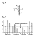
- Fig. 6 is a longitudinal sectional view showing temperature measuring points in a soldered portion.
- Fig. 7 is a graph showing temperatures of each point in a soldered portion.
- Fig. 8 is a graph showing relationships between electric power during heating and temperatures in a soldered portion or a plated portion.
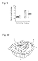
- Fig. 9 is a graph showing controlling ranges of electric power for heating in the case in which a soldered portion is cooled and the case in which it is not cooled.
- Fig. 10 is a perspective view showing a fuel tank.
- Fig. 11 is a perspective view showing a state in which a pipe is soldered to a fuel tank.
- Fig. 12 is a longitudinal sectional view showing a soldered portion in detail.
- Figs. 13A and 13B are longitudinal sectional views showing inferior qualities which occur in soldered portions.
- a fuel tank 1 (first metallic member) has Sn-Zn alloy plating M1 plated on the internal and external surface of raw material 1a made of Fe.
- a pipe (second metallic member) P in which Sn-Zn alloy plating M2 is plated on the internal and external surfaces is inserted under pressure.
- description of internal plating is omitted.
- a ring of solder S is fitted on the pipe P, and the solder S is heat-melted by an electrode for high frequency heating (not shown) displaced in close to the solder S.
- Figs. 2B and 2C show conditions in which the solder S is solidified. As shown in Fig.
- the plating M1 and the plating M2 are alloyed to the solder S, and a Zn-rich layer R is formed.
- the fuel tank 1 and the pipe P are coated, preferably after carrying out the pretreatment process, and they are covered with a coating film C.
- the contact corrosion between the plating and the solder is prevented since the Zn-rich layer R is formed on the surface of the solder S, and the adhesion of films is superior because a chemical conversion coating is easily formed in the pre-treatment process. Therefore, the corrosion resistance on the surface of the solder S can be drastically improved.
- solder As a solder according to the present invention, a solder consisting of 94 to 98% by weight of Sn and 2 to 6% by weight of Ag is preferable, and third addition metals such as Zn, Cu, and Bi may be contained in an amount below 3% by weight. Furthermore, the present invention is achieved by Sn-Zn alloy plating being plated on at least one of the first and second metallic members. With respect to the other metallic member, Ni plating may be plated thereon instead of the Sn-Zn alloy plating, or nothing may be plated thereon. It is desirable that the content of Zn in the Sn-Zn alloy plating be 7 to 45% by weight.
- the thickness of the Sn-Zn alloy plating is desirably 3 to 13 ⁇ m. Furthermore, if a chromate-treated film, an organic coating film having a thickness of 1 ⁇ m or less, or an inorganic composite coating film is provided on the surface of the Sn-Zn alloy plating, the corrosion resistance is further improved.
- a connection structure of the Comparative Example was obtained in the same manner as that of Example, except that the plating components of the members A and B were changed into a component other than Sn-Zn alloy.
- connection structure was coated all over the surface so as to have a thickness of 20 ⁇ m.
- the types of solder and plating and contents of Ag and Zn (% by weight) in each connection structure are described in Table 4.
- Solder Member A Member B Example 1 Sn-Ag (Ag:3.5%) Sn-Zn (Zn:7%) Sn-Zn (Zn:7%)
- Example 2 Sn-Ag (Ag:3.5%) Sn-Zn (Zn: 30%) Sn-Zn(Zn:8%)
- Example 3 Sn-Ag (Ag:3.5%) Sn-Zn(Zn: 30%) Sn-Zn(Zn:30%)
- Example 5 Sn-Ag (Ag:3.5%) Ni Sn-Zn(Zn:8%)
- Example 6 Sn-Ag (Ag:3.5%) Sn-Zn (Z
- connection structure With respect to each connection structure, a combined corrosion test based on automobile standard (JASOM 610-92) was carried out and the corrosion resistance thereof was examined.
- 1 ⁇ NaCl aqueous solution at 35°C was sprayed on the connection structure for 2 hours, 2 ⁇ this was dried for 4 hours in air at 60°C and a relative humidity of 20 to 30%, and 3 ⁇ this was left for 2 hours in a moist environment at 50°C and a relative humidity of over 95%.
- the process of 1 ⁇ to 3 ⁇ was defined as 1 cycle, and the number of cycles until red rust was generated at the connection structure was counted.
- Comparative Example 1 the plating did not melt during soldering since it was Ni in which the melting point is high, and superior solderability and superior pipe pulling load were exhibited. However, the corrosion resistance of Comparative Example 1 was inferior, since the platings of both members thereof consisted of Ni. In addition, in Comparative Example 2, since the content of Zn in the plating was high, the oxide of Zn was formed in the porous state at an alloy layer between solder and plating, and the solderability was extremely deteriorated. Furthermore, in Comparative Example 2, the platings of member A and member B consisted of Zn and Zn-Ni for which the order of corrosion potential is quite different. Therefore, contact corrosion was generated between the plating and the members, and the corrosion resistance was more inferior.
- Fig. 3 is a graph showing relationships between Zn content and Ag content on the surface of a soldered portion in Examples 1 to 5 and Comparative Example 1.
- the larger the Zn content in the plating the more Zn-rich the Zn layer formed on the surface of Sn-Ag alloy solder.
- this Zn-rich layer contact corrosion between plating and solder is suppressed and film adhesion is improved, and the superior corrosion resistance, as described above, can thereby be obtained.
- connection members in which each Zn content was gradually made to change from 0 to 100% by weight were produced in the same manner as the above first embodiment, except for using members A and B plated with Sn-Zn alloy having the same Zn content.
- the pipe pulling load of each connection material was measured, and the results are shown in Fig. 4.
- the larger the Zn content the larger the pipe pulling load; however, the pipe pulling load is rapidly decreased if Zn content exceeds 45% by weight. This occurs because the Zn oxide in a fragile porous state is formed at the alloy layer between solder and plating.
- connection structures in which the Zn content in the plating ranges from 0 to 55% by weight a combined corrosion test was carried out under the same conditions as that of the first embodiment, and the results are described in Fig. 4.
- Fig. 4 when the Zn content is below 7% by weight, the corrosion prevention function of Zn cannot be obtained, and the corrosion resistance is rapidly decreased. Therefore, it is preferable that the Zn content in the plating be 7% by weight or more.
- Figs. 5A to 5C are drawings showing soldering methods while the pipe is cooled;
- Fig. 5A shows a method for cooling the inside of the pipe using a coolant
- Fig. 5B shows a method for cooling the outside of the pipe using a coolant
- Fig. 5C shows a method for dissipating and radiating heat by providing radiating fins on the top of the pipe.
- a connection structure was produced in the same manner as in Example 3 in the above first embodiment in addition to using the cooling methods shown in Figs. 5A to 5C. Then, the cooling effects were examined by measuring the temperature at the position shown in Fig.
- Fig. 7 is a graph showing temperatures of each position (A, B, and C) shown in Fig. 6 in the cooling methods of (a-1), (a-3), and (c).
- the temperature in the case of non-cooling was also described as a control.
- the cooling method of (a-3) the temperature at point A was lowered below the required heating temperature (about 340°C) by overcooling, and the incomplete penetration of solder thereby occurred.
- the cooling method of (c) there was little difference in temperature from the case of non-cooling.
- connection structures were soldered, except that cooling methods were changed and connection structures were thereby produced. Then, variously properties of produced connection structures were tested, and the results are also described in Table 7.
- an epoxy-type or melamine-type coating material was coated on the connection structure after soldering, so as to have a thickness of about 20 ⁇ m, it was dried for a standard time, and the coating was thereby formed.
- the coating was soaked in ion exchanged water at 40°C for 240 hours and was taken out, cross cut patterns 1 by 1 mm were scored on the surface of pipe by knife, and the film adhesion was evaluated by peeling cellophane tape from the cross cut patterns.
- the electric power for heating be 1.7 kW or less in the case of non-cooling. Therefore, in the case of non-cooling, as shown in Fig. 9, the electric power for heating must be controlled ranging from 1.6 to 1.7 kW, that is, within a range of 0.1 kW.
- the temperature at point B after cooling is not very rapidly increased relative to the increase of the electric power for heating, as shown in Fig. 8.
- a temperature at point B can be lowered to 500°C or less, even if the electric power for heating is raised to about 1.9 kW.
- the electric power for heating may be controlled ranging from 1.6 to 1.9 kW, that is, within the range of 0.3 kW. This is very important in order to stabilize the qualities. That is, in the case of soldering, a target temperature by heating must be controlled at a level which is similar to the lower limit, since the prevention of heat degradation at plated portions has been regarded as important for some time.
- the allowable range of heating temperature is narrow, incomplete penetration of the solder easily occurs due to variation of heating temperature, since the temperature at soldered portion (point A) fluctuates greatly depending on the distance between an electrode and solder, even if the electric power is the same.
- the allowable range of heating temperature is broadened by cooling, the dispersion of heating temperature of the solder can be absorbed, and the qualities can be stabilized even by simple control.
- the present invention is not limited to such a structure comprising a fuel tank and a pipe, and it can be applied to any connection structures for metallic components.
- the heat degradation of plating and the contact corrosion between solder and plating can be prevented, solderability can be improved, and qualities such as the corrosion resistance and connecting strength at the connection structure can be improved, since Sn-Zn alloy is plated on at least one of first and second metallic members and Sn-Ag alloy is used as a solder.
Landscapes
- Engineering & Computer Science (AREA)
- Mechanical Engineering (AREA)
- Chemical & Material Sciences (AREA)
- Materials Engineering (AREA)
- Coating With Molten Metal (AREA)
- Electroplating Methods And Accessories (AREA)
- Non-Disconnectible Joints And Screw-Threaded Joints (AREA)
- Pressure Welding/Diffusion-Bonding (AREA)
- Ceramic Products (AREA)
Abstract
Description
| Alloy Names | Symbols | Melting Points | Primary Uses | Evaluation |
| Lead-tin alloy | Pb- | 200 | Soldering, Plating | Good |
| Tin-silver alloy | Sn-Ag | 215 | Soldering | Good |
| Tin-antimony alloy | Sn- | 220 | Soldering | Good |
| Tin-zinc alloy | Sn-Zn | 230 | Plating | Good |
| Zinc | Zn | 420 | Plating | Bad |
| Zinc-aluminum alloy | Zn-5Al | 361 | Soldering, Plating | Bad |
| Aluminum-silicone alloy | Al-Si | 585 | Plating | Bad |
| Silver-copper alloy | Ag-Cu | 780 | Brazing | Bad |
| Copper-zinc alloy | Cu-40Zn | 890 | Brazing | Bad |
| Plating Metal | Zn | Zn-Ni | Al-Si | Sn-Zn | Sn | Cu | Ag |
| Internal corrosion resistance | Bad | Average | Good | Good | Bad | Bad | Bad |
| External corrosion resistance | Bad | Bad | Good | Good | Good | Bad | Good |

Additionally, the thickness of the Sn-Zn alloy plating is desirably 3 to 13 µm. Furthermore, if a chromate-treated film, an organic coating film having a thickness of 1 µm or less, or an inorganic composite coating film is provided on the surface of the Sn-Zn alloy plating, the corrosion resistance is further improved.
| Solder | Member A | Member B | |
| Example 1 | Sn-Ag (Ag:3.5%) | Sn-Zn (Zn:7%) | Sn-Zn (Zn:7%) |
| Example 2 | Sn-Ag (Ag:3.5%) | Sn-Zn (Zn: 30%) | Sn-Zn(Zn:8%) |
| Example 3 | Sn-Ag (Ag:3.5%) | Sn-Zn(Zn: 30%) | Sn-Zn(Zn:30%) |
| Example 4 | Sn-Ag (Ag:3.5%) | Sn-Zn(Zn:45%) | Sn-Zn(Zn:45%) |
| Example 5 | Sn-Ag (Ag:3.5%) | Ni | Sn-Zn(Zn:8%) |
| Example 6 | Sn-Ag (Ag:3.5%) | Sn-Zn (Zn:55%) | Sn-Zn (Zn:55%) |
| Comparative Example 1 | Sn-Ag (Ag:3.5%) | Ni | Ni |
| Comparative Example 2 | Sn-Ag (Ag:3.5%) | Zn | Zn-Ni |
| Zn Content (wt%) | Pipe Pulling Load (kgf) | Solderability | Corrosion Resistance (Number of Cycles until Rust Appears) | ||
| Member A | Member B | ||||
| Example 1 | 7 | 8 | 955 | o ○ | 22 |
| Example 2 | 30 | 8 | 953 | o ○ | 26 |
| Example 3 | 30 | 30 | 948 | o ○ | 34 |
| Example 4 | 45 | 45 | 880 | O | 42 |
| Example 5 | 0 | 8 | 950 | o ○ | 20 |
| Example 6 | 55 | 55 | 600 | Δ | 47 |
| Comparative Example 1 | 0 | O | 950 | o ○ | 10 |
| Comparative Example 2 | 100 | 94 | 20 | × | 5 |
| Cooling Methods | (a) Pipe Inside Cooling | (b) Pipe Outside Cooling | (c)Fm Cooling | |||
| Coolant | a-1 | a-2 | a-3 | b-1 | b-2 | f |
| Air or Gas | Water | Steam or | Air or Gas | Water Mist | Nothing | |
| Cooling Effect | O | o ○ | o ○ | o ○ | o ○ | × |
| Solder Quality | o ○ | X | X | X | X | - |
| Corrosion Resistance | o ○ | - | - | - | - | Δ (Conventional Property) |
| Total Evaluation | o ○ | × | × | × | × | × |
| Plating | Solder | Cooling Methods | Pipe Pulling Strength (kgf) | Solderability | Plating Corrosion Resistance | Film Adhesion Adhesion | Coating Corrosion Resistance |
| Pb-Sn | Pb-Sn | Nothing | 880 | o ○ | 3 | × | 22 |
| Pb-Sn | Pb-Sn | a-1 | 870 | o ○ | 6 | O | 42 |
| Pb-Sn | Pb-Sn | a-3 | 877 | × | - | - | - |
| Sn-Zn | Sn-Ag | Nothing | 950 | o ○ | 8 | X | 24 |
| Sn-Zn | Sn-Ag | a-1 | 955 | o ○ | 16 | | 60 |
| Sn-Zn | Sn-Ag | a-3 | 947 | X | - | - | - |
| Zn | Sn-Ag | Nothing | 948 | Δ | 7 | X | 34 |
| Zn | Sn-Ag | a-1 | 950 | Δ | 16 | | 50 |
Claims (16)
- A connection structure for metallic members in which a first metallic member and a second metallic member are connected by solder, wherein Sn-Zn alloy is plated on at least one of said first metallic member and said second metallic member, and said solder consists of Sn-Ag alloy.
- A connection structure for metallic members as recited in claim 1, wherein a Zn-rich layer is provided on the surface of a portion of which said solder and said plating melt each other by alloying Sn-Zn alloy plating in said solder.
- A connection structure for metallic members as recited in claim 1, wherein said Sn-Zn alloy plating consists of 93 to 55% by weight of Sn and 7 to 45% by weight of Zn.
- A connection structure for metallic members as recited in claim 1, wherein said solder consists of 94 to 98% by weight of Sn and 2 to 6% by weight of Ag.
- A connection structure for metallic members as recited in claim 1, wherein said solder contains at least one of Zn, Cu, and Bi, in a total amount of 3% by weight or less.
- A connection structure for metallic members as recited in claim 1, wherein said solder has a thickness of 3 to 13 µm.
- A connecting method for a connection structure for metallic members, comprising:plating Sn-Zn alloy on at least one of a first metallic member and a second metallic member;using Sn-Ag alloy as solder; andconnecting said first metallic member and said second metallic member by said solder while cooling the connected portion.
- A connecting method for a connection structure for metallic members as recited in claim 7, further comprising:
forming a Zn-rich layer on the surface of a portion of which said solder and said plating melt each other by alloying Sn-Zn alloy plating in said solder. - A connecting method for a connection structure for metallic members as recited in claim 7, wherein said Sn-Zn alloy plating consists of 93 to 55% by weight of Sn and 7 to 45% by weight of Zn.
- A connecting method for a connection structure for metallic members as recited in claim 7, wherein said solder consists of 94 to 98% by weight of Sn and 2 to 6% by weight of Ag.
- A connecting method for a connection structure for metallic members as recited in claim 7, wherein said solder contains at least one of Zn, Cu, and Bi, in a total amount of 3% by weight or less.
- A connecting method for a connection structure for metallic members as recited in claim 7, wherein said solder has a thickness of 3 to 13 µm.
- A connecting method for a connection structure for metallic members as recited in claim 7, wherein said first metallic member is a container and said second metallic member is a pipe.
- A connecting method for a connection structure for metallic members as recited in claim 13, wherein said pipe is cooled by flowing coolant in the inside thereof.
- A connecting method for a connection structure for metallic members as recited in claim 13, wherein said pipe is cooled by spraying coolant in the external surface thereof.
- A connecting method for a connection structure for metallic members as recited in claim 13, wherein said pipe is cooled by providing radiating members at an end thereof.
Applications Claiming Priority (3)
| Application Number | Priority Date | Filing Date | Title |
|---|---|---|---|
| JP18564799 | 1999-06-30 | ||
| JP18564799A JP3762146B2 (en) | 1999-06-30 | 1999-06-30 | Metal member joining structure and joining method |
| PCT/JP2000/004350 WO2001002121A1 (en) | 1999-06-30 | 2000-06-30 | Structure and method for joining metal members |
Publications (3)
| Publication Number | Publication Date |
|---|---|
| EP1118413A1 true EP1118413A1 (en) | 2001-07-25 |
| EP1118413A4 EP1118413A4 (en) | 2005-09-28 |
| EP1118413B1 EP1118413B1 (en) | 2007-04-04 |
Family
ID=16174439
Family Applications (1)
| Application Number | Title | Priority Date | Filing Date |
|---|---|---|---|
| EP00940905A Expired - Lifetime EP1118413B1 (en) | 1999-06-30 | 2000-06-30 | Structure and method for joining metal members |
Country Status (8)
| Country | Link |
|---|---|
| US (1) | US6534195B1 (en) |
| EP (1) | EP1118413B1 (en) |
| JP (1) | JP3762146B2 (en) |
| KR (1) | KR100432186B1 (en) |
| CN (1) | CN1146484C (en) |
| CA (1) | CA2341725C (en) |
| DE (1) | DE60034209T2 (en) |
| WO (1) | WO2001002121A1 (en) |
Cited By (1)
| Publication number | Priority date | Publication date | Assignee | Title |
|---|---|---|---|---|
| EP2253906A4 (en) * | 2008-10-02 | 2014-11-12 | Panasonic Corp | METHOD FOR MANUFACTURING MECHANICAL DEVICE, AND REFRIGERATING CYCLE DEVICE THUS MANUFACTURED |
Families Citing this family (11)
| Publication number | Priority date | Publication date | Assignee | Title |
|---|---|---|---|---|
| US6652990B2 (en) * | 1992-03-27 | 2003-11-25 | The Louis Berkman Company | Corrosion-resistant coated metal and method for making the same |
| US6794060B2 (en) * | 1992-03-27 | 2004-09-21 | The Louis Berkman Company | Corrosion-resistant coated metal and method for making the same |
| JP3910853B2 (en) * | 2002-01-18 | 2007-04-25 | 東洋鋼鈑株式会社 | Surface-treated steel sheet for electronic parts and manufacturing method thereof |
| JP4143478B2 (en) * | 2002-10-02 | 2008-09-03 | アルプス電気株式会社 | Solder connection structure and solder connection method for electronic parts |
| US20060104033A1 (en) * | 2004-11-12 | 2006-05-18 | Chih-Chiang Yeh | Connection structure of thermal tube and heat dissipation fins |
| KR100766702B1 (en) | 2006-10-30 | 2007-10-12 | 현대중공업 주식회사 | Long service life of ship ballast tank |
| CN101896049A (en) * | 2009-05-19 | 2010-11-24 | 晟铭电子科技股份有限公司 | A cooling module and its manufacturing method |
| JP6074648B2 (en) * | 2012-07-20 | 2017-02-08 | パナソニックIpマネジメント株式会社 | Tube member assembly and heat exchanger of refrigeration cycle apparatus |
| CN103192148A (en) * | 2013-01-25 | 2013-07-10 | 鸿特机械发展(上海)有限公司 | Cutter bar connecting method of welded type single-blade gun drill |
| CN107097015A (en) * | 2017-06-07 | 2017-08-29 | 廊坊邦壮电子材料有限公司 | A kind of silver alloy solder and its preparation technology |
| CN116475700B (en) * | 2023-04-28 | 2025-08-19 | 哈尔滨工业大学 | Method for brazing and connecting skutterudite and copper electrode by using copper-tin-phosphorus brazing filler metal |
Family Cites Families (9)
| Publication number | Priority date | Publication date | Assignee | Title |
|---|---|---|---|---|
| US4695428A (en) * | 1986-08-21 | 1987-09-22 | J. W. Harris Company | Solder composition |
| JPH0577032A (en) * | 1991-09-18 | 1993-03-30 | Nippon Light Metal Co Ltd | Method for brazing metal material |
| DE4221167C2 (en) * | 1992-06-27 | 1997-08-14 | Hille & Mueller | Method for producing a multilayer pipe made of metal |
| GB2289691B (en) * | 1994-03-14 | 1999-09-29 | Berkman Louis Co | Coated metal |
| EP0700239A1 (en) | 1994-08-31 | 1996-03-06 | AT&T Corp. | Articles including solderable zinc surfaces |
| JP3744972B2 (en) * | 1995-06-20 | 2006-02-15 | ハリマ化成株式会社 | Solder bonding method |
| WO1997009455A1 (en) * | 1995-09-01 | 1997-03-13 | Sarnoff Corporation | Soldering composition |
| CN1087994C (en) * | 1995-09-29 | 2002-07-24 | 松下电器产业株式会社 | Lead-free solder |
| JP3311282B2 (en) * | 1997-10-13 | 2002-08-05 | 株式会社東芝 | Method of joining metal members and joined body |
-
1999
- 1999-06-30 JP JP18564799A patent/JP3762146B2/en not_active Expired - Lifetime
-
2000
- 2000-06-30 KR KR10-2001-7002568A patent/KR100432186B1/en not_active Expired - Lifetime
- 2000-06-30 EP EP00940905A patent/EP1118413B1/en not_active Expired - Lifetime
- 2000-06-30 CA CA002341725A patent/CA2341725C/en not_active Expired - Lifetime
- 2000-06-30 DE DE60034209T patent/DE60034209T2/en not_active Expired - Lifetime
- 2000-06-30 WO PCT/JP2000/004350 patent/WO2001002121A1/en not_active Ceased
- 2000-06-30 CN CNB008012318A patent/CN1146484C/en not_active Expired - Lifetime
- 2000-06-30 US US09/784,454 patent/US6534195B1/en not_active Expired - Lifetime
Cited By (1)
| Publication number | Priority date | Publication date | Assignee | Title |
|---|---|---|---|---|
| EP2253906A4 (en) * | 2008-10-02 | 2014-11-12 | Panasonic Corp | METHOD FOR MANUFACTURING MECHANICAL DEVICE, AND REFRIGERATING CYCLE DEVICE THUS MANUFACTURED |
Also Published As
| Publication number | Publication date |
|---|---|
| DE60034209T2 (en) | 2007-12-20 |
| EP1118413B1 (en) | 2007-04-04 |
| CN1146484C (en) | 2004-04-21 |
| KR20010079709A (en) | 2001-08-22 |
| EP1118413A4 (en) | 2005-09-28 |
| JP3762146B2 (en) | 2006-04-05 |
| CA2341725C (en) | 2005-06-28 |
| WO2001002121A1 (en) | 2001-01-11 |
| CN1315894A (en) | 2001-10-03 |
| US6534195B1 (en) | 2003-03-18 |
| JP2001009569A (en) | 2001-01-16 |
| KR100432186B1 (en) | 2004-05-22 |
| CA2341725A1 (en) | 2001-01-11 |
| DE60034209D1 (en) | 2007-05-16 |
Similar Documents
| Publication | Publication Date | Title |
|---|---|---|
| JP4339690B2 (en) | Alloy compositions and methods for low temperature fluxless brazing | |
| US6534195B1 (en) | Connection structure for metallic members and connecting method therefor | |
| US5553640A (en) | Stainless steel strip plated with brazing alloy for multilayer tube manufacturing | |
| JP3800928B2 (en) | Steel plate for high corrosion resistant fuel tank | |
| JP2000104180A (en) | Surface treated steel sheet for fuel containers with excellent corrosion resistance, workability and weldability | |
| AU718855B2 (en) | Rustproof steel sheet for automobile fuel tank with excellent resistance weldability corrosion resistance and press moldability | |
| KR101331975B1 (en) | Composition having a corrosion protection layer and process for producing it | |
| EP1394282A1 (en) | Fuel tank or fuel pipe exhibiting excellent corrosion resistance and method for manufacturing the same | |
| JP3133231B2 (en) | Rust-proof steel plate for fuel tanks with excellent workability, corrosion resistance and weldability | |
| JP2008254053A (en) | Spot welding method for tin-plated steel sheet | |
| KR20050085603A (en) | Brazing sheet product having a clad layer and a coated layer of iron alloy and method of its manufacture | |
| KR960005301B1 (en) | Laminated steel sheet for cans | |
| JP3859941B2 (en) | Automotive fuel tank with excellent corrosion resistance | |
| JP3283826B2 (en) | Automotive fuel container with excellent corrosion resistance | |
| JP3849398B2 (en) | Surface-treated steel sheet for fuel containers with excellent corrosion resistance of deteriorated gasoline | |
| JP2000176644A (en) | Arc welding method for Al-based plated steel sheet | |
| JP4419262B2 (en) | Steel plate for high corrosion resistant fuel tank | |
| JPH11129387A (en) | High corrosion resistant steel plate for fuel tank | |
| JPH0689475B2 (en) | Steel plate for fuel container | |
| JPS61266596A (en) | Steel sheet for fuel container | |
| JPH0241594B2 (en) | ||
| JPS61270390A (en) | Steel sheet for fuel vessel | |
| JPH1067235A (en) | Automotive fuel container with excellent corrosion resistance | |
| JPH07328764A (en) | Manufacture of copper/aluminum joined body | |
| JPH11151777A (en) | High corrosion resistant steel plate for fuel tank |
Legal Events
| Date | Code | Title | Description |
|---|---|---|---|
| PUAI | Public reference made under article 153(3) epc to a published international application that has entered the european phase |
Free format text: ORIGINAL CODE: 0009012 |
|
| 17P | Request for examination filed |
Effective date: 20010227 |
|
| AK | Designated contracting states |
Kind code of ref document: A1 Designated state(s): AT BE CH CY DE DK ES FI FR GB GR IE IT LI LU MC NL PT SE |
|
| AX | Request for extension of the european patent |
Free format text: AL;LT;LV;MK;RO;SI |
|
| RIC1 | Information provided on ipc code assigned before grant |
Free format text: 7B 23K 1/20 A, 7B 23K 1/19 B, 7B 23K 35/26 B |
|
| A4 | Supplementary search report drawn up and despatched |
Effective date: 20050811 |
|
| GRAP | Despatch of communication of intention to grant a patent |
Free format text: ORIGINAL CODE: EPIDOSNIGR1 |
|
| RBV | Designated contracting states (corrected) |
Designated state(s): DE FR GB |
|
| GRAS | Grant fee paid |
Free format text: ORIGINAL CODE: EPIDOSNIGR3 |
|
| GRAA | (expected) grant |
Free format text: ORIGINAL CODE: 0009210 |
|
| AK | Designated contracting states |
Kind code of ref document: B1 Designated state(s): DE FR GB |
|
| REG | Reference to a national code |
Ref country code: GB Ref legal event code: FG4D |
|
| REF | Corresponds to: |
Ref document number: 60034209 Country of ref document: DE Date of ref document: 20070516 Kind code of ref document: P |
|
| ET | Fr: translation filed | ||
| PLBE | No opposition filed within time limit |
Free format text: ORIGINAL CODE: 0009261 |
|
| STAA | Information on the status of an ep patent application or granted ep patent |
Free format text: STATUS: NO OPPOSITION FILED WITHIN TIME LIMIT |
|
| 26N | No opposition filed |
Effective date: 20080107 |
|
| REG | Reference to a national code |
Ref country code: FR Ref legal event code: PLFP Year of fee payment: 17 |
|
| REG | Reference to a national code |
Ref country code: FR Ref legal event code: PLFP Year of fee payment: 18 |
|
| REG | Reference to a national code |
Ref country code: FR Ref legal event code: PLFP Year of fee payment: 19 |
|
| PGFP | Annual fee paid to national office [announced via postgrant information from national office to epo] |
Ref country code: FR Payment date: 20180511 Year of fee payment: 19 |
|
| PGFP | Annual fee paid to national office [announced via postgrant information from national office to epo] |
Ref country code: GB Payment date: 20180627 Year of fee payment: 19 |
|
| REG | Reference to a national code |
Ref country code: DE Ref legal event code: R082 Ref document number: 60034209 Country of ref document: DE Representative=s name: WEICKMANN & WEICKMANN PATENT- UND RECHTSANWAEL, DE Ref country code: DE Ref legal event code: R081 Ref document number: 60034209 Country of ref document: DE Owner name: HONDA GIKEN KOGYO K.K., JP Free format text: FORMER OWNERS: HONDA GIKEN KOGYO K.K., TOKYO, JP; YACHIYO KOGYO K.K., SAYAMA, SAITAMA, JP |
|
| PGFP | Annual fee paid to national office [announced via postgrant information from national office to epo] |
Ref country code: DE Payment date: 20190618 Year of fee payment: 20 |
|
| GBPC | Gb: european patent ceased through non-payment of renewal fee |
Effective date: 20190630 |
|
| PG25 | Lapsed in a contracting state [announced via postgrant information from national office to epo] |
Ref country code: GB Free format text: LAPSE BECAUSE OF NON-PAYMENT OF DUE FEES Effective date: 20190630 |
|
| PG25 | Lapsed in a contracting state [announced via postgrant information from national office to epo] |
Ref country code: FR Free format text: LAPSE BECAUSE OF NON-PAYMENT OF DUE FEES Effective date: 20190630 |
|
| REG | Reference to a national code |
Ref country code: DE Ref legal event code: R071 Ref document number: 60034209 Country of ref document: DE |